

Page 1

Using the Bay Command Console (BCC)
BayRS Version 13.00
Site Manager Software Version 7.00
BCC Version 4.05
Part No. 303562-A Rev. 00
October 1998
Page 2

4401 Great America Parkway 8 Federal Street
Santa Clara, CA 95054 Billerica, MA 01821
Copyright © 1998 Bay Networks, Inc.
All rights reserved. Pr inted in the USA. October 1998.
The information in this document is subject to change without notice. The statements, configurations, technical data,
and recomm endations in this document are believed to be accurate and reliable, but are presented without express or
implied warranty. Users must take full responsibility for their appli cations of any products s pecified in this document.
The information in this document is proprietary to Bay Networks, Inc.
The software described in this document is furnished under a license agreement and may only be used in accordance
with the te rms of that license. A summary of the S oftware License is included in this document.
Trademarks
ACE, AN, BCN, BLN, BN, FRE, Optivi ty, PPX, Quick2Config, and Bay Networks are registered trademarks and
Advanced Remote Node, ANH, ARN, ASN, BayRS, BaySecure, BayS tack, BCC, SPEX, System 5000, and the Bay
Networks logo are trademarks of Bay Networks, Inc.
Microsoft , MS, MS-DOS, Win32, Windows, and W indows NT are r egistered tr ademarks of Microsoft Corporation.
All other trademarks and registered trademarks are the property of their respective owners.
Restricted Rights Legend
Use, duplication, or disclosure b y the United States Government is subject to restrict ions as set forth in subparagraph
(c)(1)(ii) of the Rights in Technical Data and Computer Software clause at DFARS 252.227-7013.
Notwithstanding any other license agreement th at may pertain to, or accompany the delivery of, this com puter
software, the rights of the Unite d States Government regarding its use, reproduction, and disclosure are as set forth in
the Commercial Computer Software-Restricted Rights clause at FAR 52.227-19.
Statement of Conditions
In the interest of improving internal design, operational function, and/or reliability, Bay Networks, Inc. reserves the
right to make changes to the products described in this document with out notice.
Bay Networks, Inc. does not assume any liability that may occur due to the use or application of the product( s) or
circuit layout(s) described herein.
Portions of the code in this software product may be Copyright © 1988, Regents of the University of California. All
rights reserved. Red istribution and use in source and binary forms of such portions are permit ted, provided that the
above copyright notice and this paragraph are duplicated in all such forms and that any documentation, advertising
materials, and other materials related to such distribution and use acknowledge that such portions of the software were
deve loped by the Uni versity of California, Berkeley. The name of the University may not be used to endorse or
promote products derived from such portions of the software without specific prior written permission.
SUCH PORTIONS OF THE SOFTWARE ARE PROVIDED “AS IS” AND WITHOUT ANY EXPRESS OR
IMPLIED WARRANTIES, INCLUDING, WITHOUT LIMITATION, THE IMPLIE D WARRANTIES OF
MERCHANTABILITY AND FITNESS FOR A PARTICULAR PURPOSE.
In additi on, the program and information contained herein are lice nsed only pursuant to a license agreement that
contains restrictions on use and discl osure (that may incorporate by reference certain limitations and notices imposed
by thir d pa rt ie s).
ii
303562-A Rev. 00
Page 3

Bay Networks, Inc. Software License Agreement
NOTICE: Please carefully read this license agreement before copying or using the accompanying software or
instal ling the hardware unit w ith pre-enabled software (each of w hich is referred to as “Software” in this Agree m ent).
BY COPYING OR USING THE SOFTWARE, YOU ACCEPT ALL OF THE TERMS AND CONDITIONS OF
THIS LICENSE AGREEMENT. THE TERMS EXPRESSED IN THIS A GREEM ENT ARE THE ONLY TERMS
UNDER WHICH BAY NETWORKS WILL PERMIT YOU TO USE THE SOFTWARE. If you do not accept these
terms and conditions, return the product, unused and in the original shipping container, within 30 days of purchase to
obtain a credit for the full purchase price.
1. License Grant. Bay Networks, Inc. (“Bay Networ ks”) grants the end user of the Softwar e (“Licensee”) a personal,
nonexcl usive, nontransferab le license: a) t o use the Software either on a singl e com puter or, if applicable, on a single
authori zed de vi ce ide ntified by hos t ID, fo r whi ch it wa s ori gi nal ly acq uir ed ; b) to cop y th e Sof tw ar e so lely f or bac kup
purposes in support of author ized use of the Software; and c) to use and copy the associated user manual solely i n
support of authorized use of the Software by Licensee. This license applies to the Software only and does not extend
to Bay Networks Agent softw are or other Bay Networks softw are products. Bay Networks Agent software or other
Bay Networks software products are licensed for use under the terms of the applicable Bay Networks, Inc. Software
License Agreement that accompanies such software and upon payment by the end user of the applicable licen se fees
for such software.
2. Restrictions on use; reservation of rights. The Software and user manuals are protected under copyr ight laws.
Bay Networks and/or its licensors retai n all title and ownership in bot h the Software and user manuals, including any
revis ions made by Bay Networks or its li censors. The copyright noti ce m ust be reproduced and included with any
copy of any por tion of the Sof tw are or use r manua ls . Licens ee may not modif y, trans late , dec ompi le, di sas semb le, use
for any compe ti ti v e an al ysis, r e v erse e ngi ne er , dis tr ib ute , o r c rea te der i vativ e w ork s fro m th e Sof twa re or u se r man ual s
or any copy, in whole or in part. Except as expressly provided in this Agreement, Licensee may not copy or transfer
the Softw are or user manual s, in whole or in part. The Software and user manuals embody Bay Networks’ and its
licenso rs’ confident ial and proprietary intellectual property. Licensee shall not sublicense, assign, or other w ise
disclos e to any third pa rty the Software, or any information abou t the operation, design, performance, or
implementation of the Software and us er manuals that is confidential to Bay Networks and its li censors; how ever,
Licensee m ay grant permission to its consul tants, subcontractors , and agents to use the Software at License e’s facility,
provided they have agreed to use the Software only in accordance with the term s of this license.
3. Limited warranty. Bay Networks warrants each item of Softwa re, as delivered by Bay Networks and properly
installed and operated on Bay Networks har dw are or other equipment it is ori ginally licensed for, to function
substantially as descri bed in its accomp anying user manual during its warranty period, which begi ns on the date
Softwar e is fi r st shi pped to Licen see . If any it em of Soft war e fai ls to so func ti on du ring i ts warr anty pe ri od, as t he so le
remedy Bay Ne tworks will at its discretion provide a suitable fi x, patch, or workaround for the problem that may be
included in a future Software release. Bay Networks further warrants to Licensee that the media o n which the
Softwar e is provided will be free from defects in materials and workmans hip under norm al use for a period of 90 days
from the date Software is first shi pped to Licensee. B ay Networks will replace defectiv e media at no charge if it is
returned to Bay Networks during the warrant y period along with proof of the date of shipment. This w arranty d oes not
apply i f the media has been d amaged as a result of accident, misuse, or abuse. The Licens ee assumes all responsibility
for selection of the Software to achieve Licensee’s intended results and for the installation, use, and results obtained
from the Software. Bay Ne tworks does not warrant a) tha t the functions contained in the software will meet the
Licensee ’s requirements, b) that the Sof tware will operate in the hardware or software comb inations that the License e
may select, c) that the operation of the Software will b e uninterrupted or error free, or d) that all defects in the
operati on of the Softw are will be corrected. Bay Networks i s not obligated to remedy any Software defect that cannot
be repro duced with the latest Software release. These warranties do not apply to the Software if it has been (i) altered,
except by Bay Networks or in accordance with its instructions; (ii) used in conjunction with another vendor’s product,
resulting in the defect; or (iii) damaged by improper environment, abuse, mi suse, accident, or negligence. THE
FOREGOING WARRANTIES AND LIMITATIONS ARE EXCLUSIVE REMEDIES AND ARE IN LIEU OF ALL
OTHER WARRANTIES EXPRESS OR I MPLIED, INCLUDI NG WITHOUT LIMITATION ANY WARRANTY OF
MERCHANTABILITY OR FITNESS FOR A P ARTICULAR PURPOSE. Licensee is responsible for the security of
303562-A Rev. 00
iii
Page 4

its own data and inform ation and for mai ntaining adequate procedures apart from the Software t o reconstruct lost or
altered files, data, or programs.
4. Limitation of liability. IN NO EVENT WILL BAY NETWORKS OR ITS LICENSORS BE LIABLE FOR ANY
COST OF SUBSTITUTE PROCUREMENT; SPECIAL, INDIRECT, INCIDENTAL, OR CONSEQUENTIAL
DAMAGES ; OR ANY DAMAGES RESULTING FROM INACCURATE OR LOST DATA OR LOSS OF USE OR
PROFITS ARISING OUT OF OR IN CONNECTION WITH THE PERFORMANCE OF THE SOFTWARE, EVEN
IF BAY NETWORKS HAS BEEN ADVISED OF THE POSSIBILITY OF SUCH DAMAGES. IN NO EVENT
SHALL THE LIABILITY OF BAY NETWORKS RELATING TO THE SOFTWARE OR THIS AGREEMENT
EXCEED THE PRICE PAID TO BAY NETWORKS FOR THE SOFTWARE LICENSE.
5. Government L i c en s ees. This provision applies to all Software and documentation acquired directly or indirectly
by or on behalf of the United States Government. The Software and documentation are commercial products, licensed
on the open market at market p rices, and were developed ent irely at pri vate expense and without the use of any U.S.
Government funds. The license to the U. S. Governmen t is granted only with restricted rights, and use, duplica tion, or
disclos ure by the U.S. Go vernment is subject to the restrictions set forth in subparagraph (c)(1) of the Comm ercial
Computer So ftware––Restricted Rights clause of FAR 52.227-19 and the limitations set out in this license for c ivilian
agencies , and subparagra ph (c)(1)(ii) of the Rights in Technical Data a nd C om p uter Software clause of DFARS
252.227-7013, for agencies of the Department of Defen se or their successors, whichever is applicable.
6. Use of Software in the European Communit y. This pr ovision applies to all Software acquired for use within the
European Comm unity. If Licensee uses the Software within a country in the European Com mu n ity, t he Software
Directive enacted by the Council of European Communities Directive dated 14 May , 1991, will apply to the
examination of the Softw are to facili tate interoperability. Licensee agrees to notify Bay Networks of any such
intended examination of the Software and may procure support and assis tance from Bay Networks.
7. Term and termination. This license is effective until terminated; however, all of the restrictions with respect to
Bay Networks’ copyright in the Software and user manuals will cease being effective at the date of expiration of the
Bay Networks copyright; those restrictions relating to use and discl osure of Bay Networ ks’ confidential information
shall continue in effect. Licensee may terminate this license at any time. The license will automatically terminate if
Licensee fails to comply with any of the terms and conditions of the license. Upon termination for any reason,
Licensee will immediately destroy or return to Bay Networks the Software, user manuals, and all copies. Bay
Networks is not liable to Licensee for damages in any form so lely by reason of the terminati on of this license.
8. Export and Re-export. License e agrees not to export, directly or indirectly, the Software or related technical data
or information without first obtaining any required export licenses or other governmental approvals. Without limiting
the fore going, Licensee, on behalf of itself and its subsidiari es and affiliates, agrees that it wil l not, without first
obtaining all export licenses and appr ovals required by the U.S. Governmen t: (i) export, re-export, transfer, or divert
any such Sof tware or technical data, or an y direct product thereof, to any country to whi ch such exports or re-exports
are rest ricted or embargoed under United States ex port control laws and regu lations, or to any national or resident of
such rest ricted or embargoed countr ies; or (ii) provide the Software or related technical data or infor mation to any
military end user or for any m ilitary end use, including the design, development, or production of any chemical,
nuclear, or biological weapons.
9. General. If any provision of this Agreement is held to be invalid or unenforceable by a court of competent
jurisdiction, the remainder of the provisions of this Agreement shall remain in full force and effect. This Agreement
will be governed by the laws of the state of California.
Should you have any quest ions concerning this Agreement, contact Bay Networks, Inc., 4401 Great America
Parkway, P.O. Box 58185, Santa Clara, California 95054-8185.
LICENSEE ACKNOW LEDGES THAT LICENSEE HAS READ THIS AGREEMENT , UNDERSTANDS IT, AND
AGREES TO BE BOUND BY ITS TERMS AND CONDITIONS. LICENSEE FUR THER AGREES THAT THIS
AGREEMENT IS THE ENTIRE AND EXCLUSIVE AGREEMENT BETWEEN BAY NETWORKS AND
LICENSEE, WHICH SUPERSEDES ALL PRIOR ORAL AND WRITTEN AGREEMENTS AND
COMMUNICATIONS BETWEEN THE PARTIES PERTAINING TO THE SUBJECT MATTER OF THIS
AGREEMENT. NO DIFFERENT OR ADDITIONAL TERMS WILL BE ENFORCEABLE AGAINST BAY
NETWORKS UNLESS BAY NETWORKS GIVES ITS EXPRESS WRITTEN CONSENT, INCLUDING AN
EXPRESS WAIVER OF THE TERMS OF THIS AGREEMENT.
iv
303562-A Rev. 00
Page 5

Contents
Preface
Before You Begin .............................................................................................................xiii
Text Convent io n s . .................. ......................................................... .................................xiv
Acronyms .........................................................................................................................xvi
Bay Networks Technical Publications ..............................................................................xvi
How to Get Help .............................................................................................................xvii
Chapter 1
Overview of the BCC
Platf o rm Requir e men ts ....................................................... ............................................1-2
Number of BCC Sessions ...............................................................................................1-2
Terminology and Concepts ................................................................................... ..........1-3
Configuration Hierarchy ............................................................................................1-3
Context .....................................................................................................................1-5
Objects, Classes, and Insta nces ........................................................ ......................1-6
BCC Instance Identifier ....................... ..... ..... .. ..... .. ..... ..... .. ..... .. ..... .. ..... ..... .. ..... .1-7
Global (Box-Wide) Objects ................................................................................1-7
Physical Device Objects ....................................................................................1-8
Parameters ............................................................................................................. 1-10
Required Parameters .......................... ..... ....... ....... ..... ....... ....... ....... ..... ....... ....1-10
Derived Parameters .........................................................................................1-10
Optional Parameters ........................................................................................1 -10
Chapter 2
Getting Started with the BCC
Entering and Exiting the BCC Interface ..........................................................................2-1
Displaying Context .......... ......................................................... .......................................2-3
Navigating in Configuration Mode .............................. ....... ....... ....... ..... ....... .. .......... ....... .2-3
Navigating with the back Command .................................. ..... .. ..... ..... .... ..... ..... .. ..... .2-3
Navigating with Configuration Commands ...............................................................2-4
303562-A Rev. 00
v
Page 6

Moving Back One or More Levels ...................................................................... 2-4
Moving Back to Root Level ................................................................................2-5
Moving Forward One or More Levels .................................................................2-5
Moving to Any Context in the Device Configuration ...........................................2-6
Displaying Configuration Data ........................................................................................2-8
Displaying the Total Device Configuration ................................................................2-8
Displaying the Configuration of One Object ........................................................... 2 -10
Using Online Help .........................................................................................................2-11
Help Commands ....................................................................................................2-11
Help Command Examples ..................................................................................... 2 -13
Chapter 3
Entering Commands and Using Command Files
Entering Commands .......................................................................................................3-1
Using Command Abbreviations ................................................................................3-2
Recalling Commands ...............................................................................................3-2
Editing Command Lines ...........................................................................................3-3
Entering Multiple Commands on a Line ....................... .......... ....... .. ....... .......... ....... .3-4
Continuing a Command Line ....................................................................................3-4
System Commands ................................................................. ....... ....... ..... ....... ....... ......3-5
Configuration Command Syntax .....................................................................................3-5
Command Syntax Requi r e men ts ................................................................... ..........3-5
Using Basic (Full) Syntax .........................................................................................3-6
Using Default Syntax ................................................................................................3-7
Using Abbreviated Syntax ........................................................................................3-7
Specifyin g Parameter Values ...... ................... ......................................................... .3-8
Required, Derived, and Other Parameters ........................................................3-8
Specifying Multiple Parameter-Value Pairs ........................................................ 3-8
Disabling, Reenabling, and Deleting a Configured Object .....................................3-10
Creating and Using BCC Command Files ....................................................................3-10
Saving Commands to a File ...................................................................................3-11
Adding Comments to a Command File ..................................................................3-11
Entering Configuration Commands from a File ......................................................3-12
Saving the Active Configuration as a Bootable Binary File ....................................3 -12
vi
303562-A Rev. 00
Page 7

Chapter 4
Tutorial: Configuring a Network Device
Creating and Modifying a Device Configuration .............................................................4-1
Disabling a Configured Object ......................................................................................4-15
Enabling a Configured Object .......................................................................................4-16
Deleting a Configured Object .......................................................................................4-17
Appendix A
System Commands
Appendix B
TCL Support
Appendix C
System show Commands
show console .................................................................................................................C-2
show hardware ..............................................................................................................C-5
show process .................................................................................................................C-7
show system ................................................................................................................C-10
Appendix D
Syntax for Module Location
Index
303562-A Rev. 00
vii
Page 8

Page 9

Figures
Figure 1-1. The Technician Interface and the BCC Interface .....................................1-1
Figure 1 -2. Sample BCC Configuration ......................................................................1-4
Figure 1-3. Configuring IP and RIP on an Ethe rnet In te r face ......... ...........................1-5
Figure 1-4. Configuring IP and RIP on an Ethe rnet In te r face ......... ...........................1-6
Figure 2 -1. Moving Away from Root Level ..................................................................2-6
Figure 2-2. Navigating to an Object in the Configuration ...........................................2-7
Figure 2-3. Navigating with the BCC Recursive Search Feature ...............................2-8
Figure 2-4. Objects You Can Configure at the Next Level ........................................2-15
Figure 4-1. Sample BCC Configuration (BCN Router) ...............................................4-3
Figure 4-2. Typical BCC Configuration Cycle .............................................................4-4
303562-A Rev. 00
ix
Page 10

Page 11

Tables
Table 2-1. BCC Help Commands ........................................................................... 2 -11
Table 3-1. Keystrokes for Editing BCC Command Lines ........................................... 3-3
Table 3-2. BCC Commands ....................................................................................3-10
Table A-1. System Commands ................................................................................ A-2
Table D-1. Syntax for Specifying Module Location per Device ................................D-1
303562-A Rev. 00
xi
Page 12

Page 13

The BCC is a command-line interface for configuring Bay Networks devices. If
you are responsible for configuring and managing Bay Networks®
AN®, ANH™, ARN™, ASN™, BN® (BCN® and BLN®), or System 5000™ routers,
read this guide to learn how to use the Bay Command Console (BCC™).
Before You Begin
This guide is intended for users who have some experience supporting a
multivendor internetworking system. You should be able to perform network
device configuration, maintenance, and troubleshooting.
Preface
303562-A Rev. 00
Because the BCC make s real -time c hanges to de vi ce c onf igura tion, B ay Networ ks
recommends that you first le arn about BCC behavior on a devi ce not connected to
your production netw ork.
xiii
Page 14

Using the Bay Command Console (BCC)
Text Conventions
This guide uses the following text conventions:
angle brackets (< >) Indicate that you choose the text to enter based on the
description inside the brackets. Do not type the
brackets when entering the command.
Example: If the command syntax is:
,
<ip_address>
ping
ping 192.32.10.12
you enter:
bold text
Indicates text tha t you need to enter and command
names and options.
Example: Enter
Example: Use the
show ip {alerts | routes
command.
dinfo
}
braces ({}) Indicate required elements in syntax descriptions
where there is more than one option. You must choose
only one of the options. Do not type the braces when
entering the command.
Example: If the command syntax is:
|
show ip {alerts
show ip alerts or show ip routes
routes
, you must enter either:
}
.
brackets ([ ]) Indicate optional elements in syntax descriptions. Do
not type the brackets when entering the command.
Example: If the command syntax is:
, you can enter either:
show ip interfaces [-alerts
show ip interfaces
or
]
show ip interfaces -alerts
.
ellipsis points (. . . ) Indicate that you repeat the last element of the
comman d as need ed .
Example: If the command syntax is:
xiv
ethernet/2/1
ethernet/2/1
needed.
[<
parameter> <value>
] . . .
, you enter
and as many parameter-value pairs as
303562-A Rev. 00
Page 15

Preface
italic text Indicates file and directory names, new terms, book
titles, and variables in command syntax descriptions.
Where a variable is two or more words, the words are
connected by an underscore.
Example: If the command syntax is:
show at <
valid_route
valid_route>
is one va riable and you subs titu te one value
for it.
screen text Indicates system output , fo r exa mple, prompts and
system messages.
Example:
Set Ba y Netw orks Tr ap Mo nito r Fil ters
vertical line ( | ) Separates choices for command keywords and
arguments. Enter only one of the choices. Do not type
the vertical line when entering the command.
Example: If the command syntax is:
show ip {alerts | rou tes}
show ip alerts
or
show ip routes
, you enter either:
, but not both.
303562-A Rev. 00
xv
Page 16

Using the Bay Command Console (BCC)
Acronyms
ARP Address Resolution Protocol
ATM asynchronous transfer mode
DCM data collection modul e
DRAM dynamic random access memory
IP Internet Protocol
IPX Internetwork Packet Exchange
LAN local area network
MAC media access control
OSPF Open Shorte st Path Fi rst
RIP Routing Information Protocol
SNMP Simple Network Management Protocol
SRM-L system resource module- link
TCP/IP Transmission Control Protoc ol/Internet Protocol
TFTP Trivial File Transfer Protocol
WAN wide area network
Bay Netwo rks Technical Publications
You can now print Bay Net works technical manuals and release notes free,
directly from the Int ernet. Go to support.bayn etworks.com/libr ary/tpubs/. Fi nd the
Bay Networks product for which you need doc umenta tion. Then locate the
specific category and model or version for your hardware or software product.
Using Adobe Acrobat Reader, you can open the manuals and release note s, sear ch
for the sections you need, and print them on most standard printers. You can
download Acrobat Reader free from the Adobe Systems Web site,
www.adobe.com.
xvi
303562-A Rev. 00
Page 17

You can purchase Bay Networks documentation sets, CDs, and selected te ch nical
publications through the Bay Networks Collateral Catalog. The catalog is loc ated
on the World Wide Web at support.baynetworks.com/catalog.html and is divided
into sections arran ged alpha betically:
• The “CD ROMs” section lists available CDs.
• The “Guides/Books” section lists books on technical topics.
• The “Technical Manuals” section li sts available print ed documentation sets.
Make a note of the part numbers and prices of the items that you want to order.
Use the “Marketing Collateral Catalog description” link to place an order and to
print the order form.
How to Get Help
For product assista nce, support contracts, or informati on abou t educational
services, go to the following URL:
http://www.baynetworks.com/corporate/contacts/
Preface
303562-A Rev. 00
Or telephone the Bay Networks Technical Solutions Center at:
800-2LANWAN
xvii
Page 18

Page 19
Chapter 1
Overview of the BCC
The BCC is a command-line interface for configuring Bay Networks devices.
After logging on to a de vi ce, you access the BCC by ente ring the
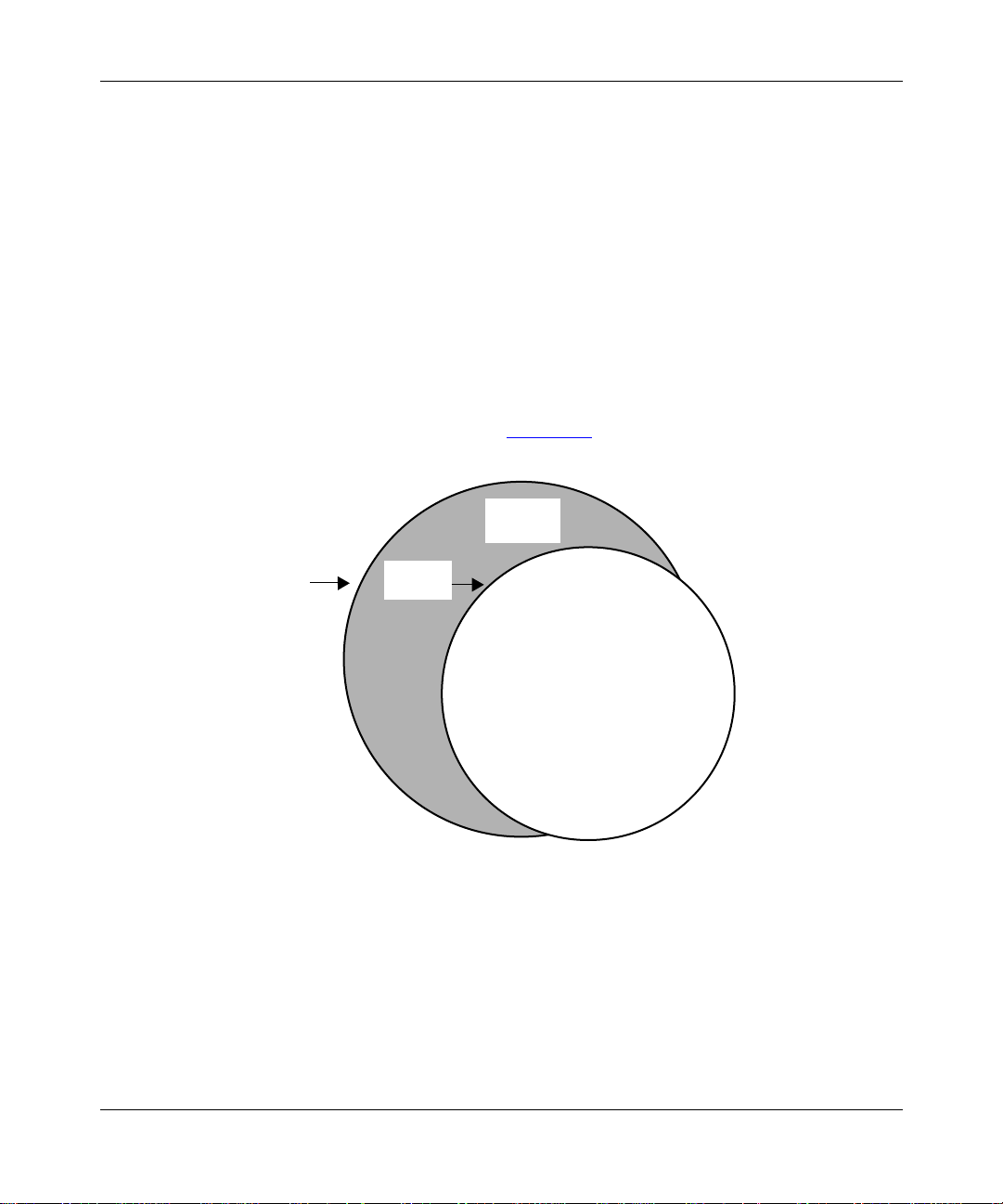
the Technician Interface prompt (Figure 1-1
Technician
Interface
).
command at
bcc
Login
Figure 1-1. The Technician Interface and the BCC Interface
Access
the BCC
BCC
BCC0001B
303562-A Rev. 00
1-1
Page 20

Using the Bay Command Console (BCC)
From the
prompt, you can:
bcc>
• Execute any system command not classified as “Te chnician Interface only”
(see Appendix A, “
• Execute configur ation commands to perfor m tasks such as creating or deletin g
IP interfaces on the router. Enter BCC configuration mode by entering the
config
command at the bcc> prompt.
Note:
For a list of services you can configure using the BCC, see the Release
Notes. You can obtain a complete hierarchical listing of all object s
configurable on a device by entering the
prompt.
Platform Requirements
The BCC runs on AN, ANH, ARN, ASN , System 5000, and BN platforms
including ARE, FRE
• 16 MB of dynamic RAM (DRAM)
• 2 MB of free memory space available when you start the BCC
System Commands”).
help tree -all
®
, and FRE-2 processor modules. Each slot must have:
command at any BCC
If you try to start the BCC with insufficient DRAM or free memory on a slot, the
BCC returns an error message. In that case, use Site Manager instead of the BCC.
Number of BCC Sessions
You can open one BCC session per slot in read-write (configur ation) mode. Other
users can open additional BCC sessions in read-only (nonconfiguration) mode on
the same slot, depending on available memory. Each BCC session is mutually
exclusi ve. If you make a change during a BCC session in read-write mode, this
change does not appear in other BCC sessions.
1-2
303562-A Rev. 00
Page 21

Terminology and Concepts
This section describes key terms and concepts of the BCC interface.
Configuration Hierarchy
The BCC configuration hierarchy begins at a root-level object, called box for
AN/ANH, ARN, and BN platforms, and stack for ASN and System 5000
platforms. Under the root- level object are branch obje cts such as interfaces and
protocols that fan out from the root level in a tree hierarchy.
Overview of the BCC
You use the
help tree -all
and
show config -all
commands to display the
configura tion hierarchy of a Bay Networks route r.
• The
help tre e -all
command displays the hierarchy of every object you can
configure .
• The
show config -all
command displays the hierarchy of objects you have
configured.
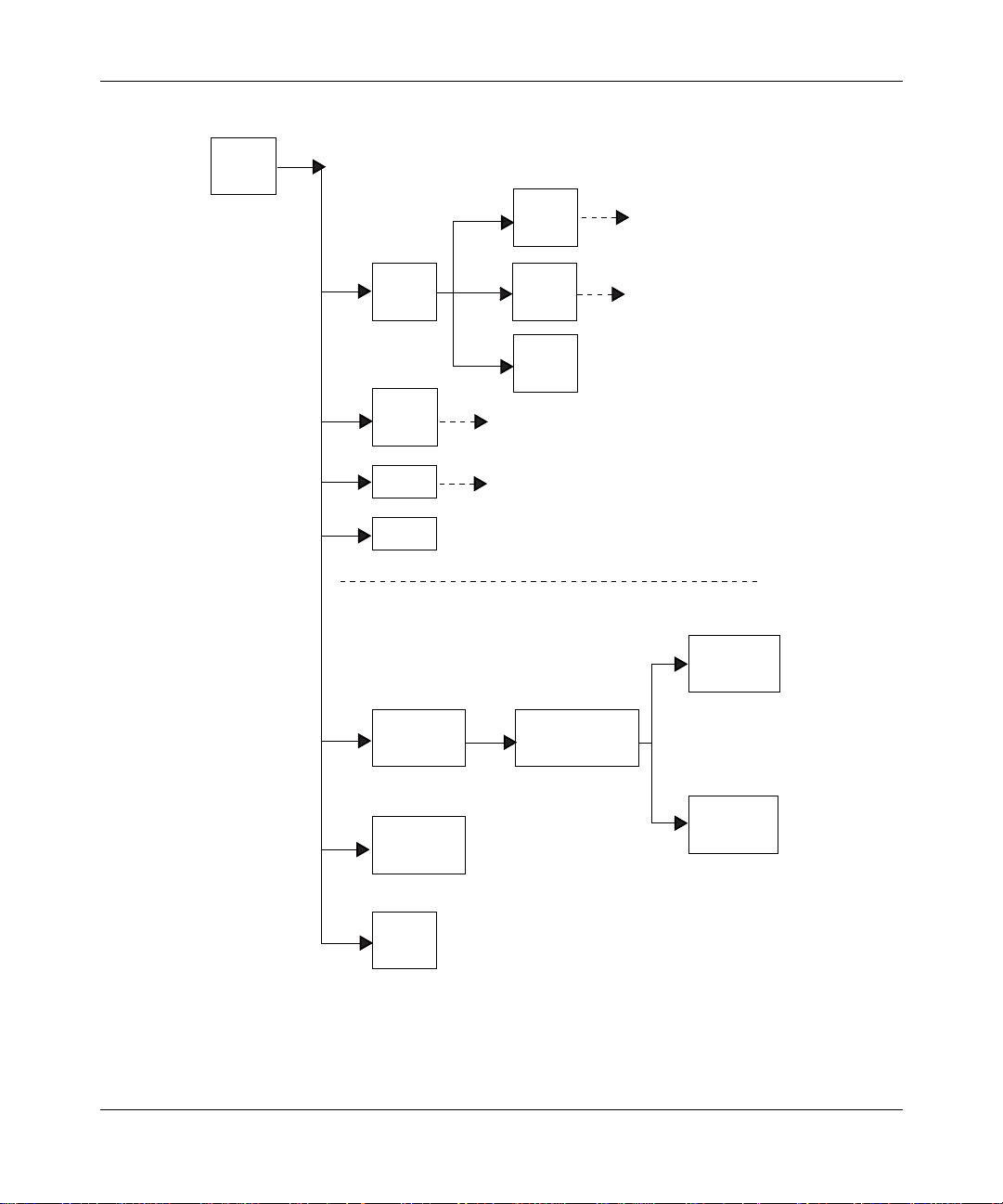
Figure 1-2
illustrates a sample BCC conf igur ation for an AN, BN, or ARN router.
• Box contains the global ob jects IP, SNMP, T e lnet, and TFTP, plus the physical
interface objects ethernet/2/1, ethernet/2/2, and serial/3/1.
• Global IP contains the global obje cts ARP, RIP, and OSPF.
303562-A Rev. 00
1-3
Page 22
Using the Bay Command Console (BCC)
box
(root)
ospf
(protocol)
ip
(protocol)
snmp
(protocol)
telnet
(protocol)
tftp
(protocol)
INTERFACE-SPECIFIC OBJECTS
(Services supported on a specific slot)
ethernet/2/1
(interface)
ethernet/2/2
(interface)
arp
(protocol)
rip
(protocol)
BOX-WIDE/GLOBAL OBJECTS
(Services supported on all slots)
ip/1.2.3.4/255.0.0.0
(protocol)
ospf/1.2.3.4
(protocol)
arp/1.2.3.4/1
(protocol)
1-4
serial/3/1
(interface)
BCC0012C
Figure 1-2. Sample BCC Configuration
303562-A Rev. 00
Page 23
Overview of the BCC
You use BCC commands to create new objects and to modify or delete objects in
an existing conf iguration hierarchy. You begin at root level in BCC configur at ion
mode and navigate to objects in the device configuration tree.
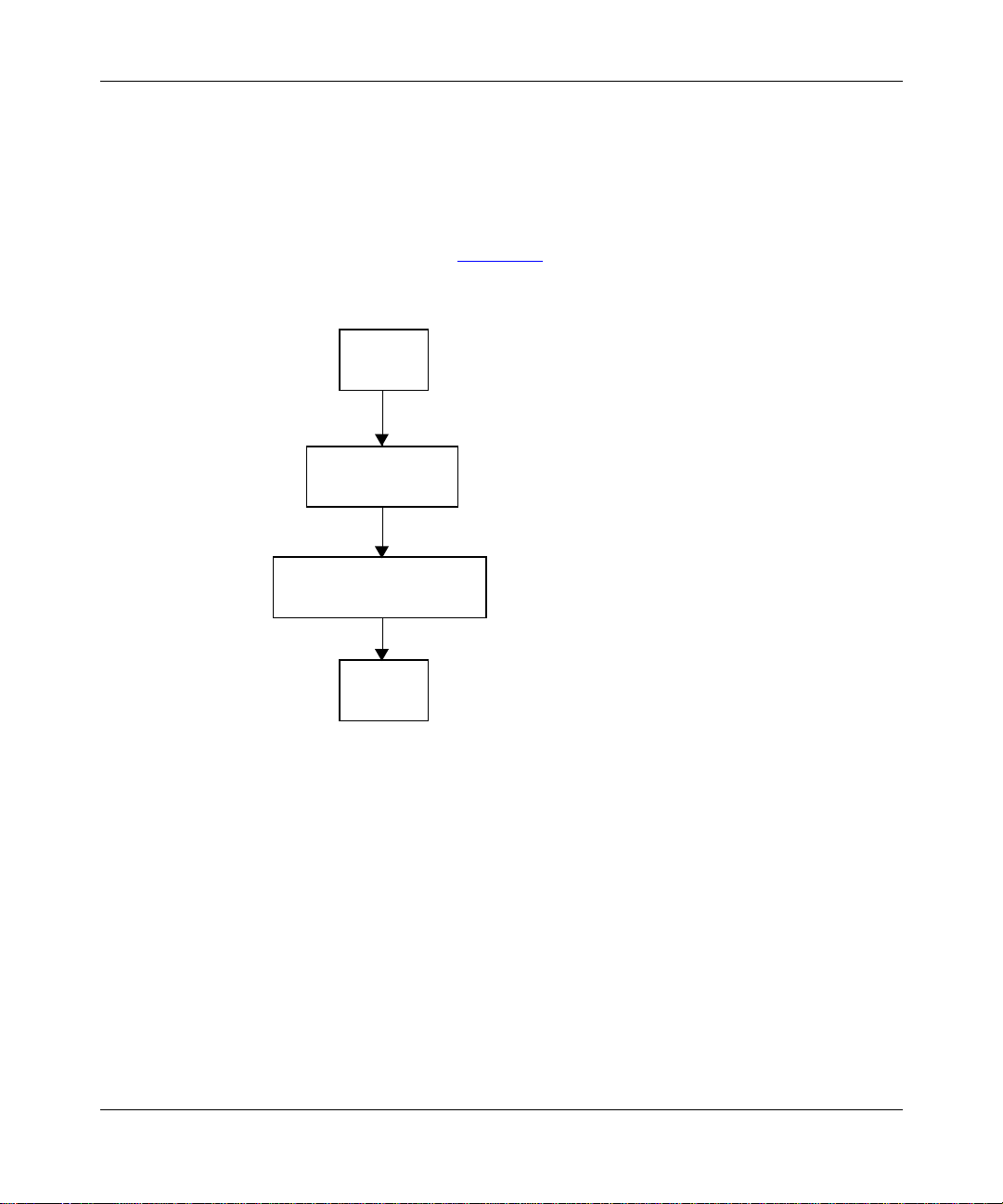
For example , on a BLN router, you can use BCC commands to add a ne w physi cal
interface (such as Ether net) on box, add IP to the Ethernet interface, and then add
RIP to IP on that inte rface . Figure 1-3
shows the sequence of commands
necessary to build this configuration.
box
box# ethernet/2/1
Ethernet
Slot 2
Connection 1
ethernet/2/1# ip address 1.2.3.4 mask 255.0.0.0
IP
Address 1.2.3.4
Mask 255.0.0.0
Context
303562-A Rev. 00
ip/1.2.3.4/255.0.0.0# rip
rip/1.2.3.4
rip/1.2.3.4#
BCC0017A
Figure 1-3. Configuring IP and RIP on an Eth ernet Interface
Your working location within the BCC configuration tree is referred to as the
context. Just as a UNIX file system has a current working directory within which
you can add, modify, or delete files, the BCC configuration tree has a current
working context, within which you can add, modify, disa ble, reenable, or delete
objects.
1-5
Page 24
Using the Bay Command Console (BCC)
The BCC underst ands the context of an object in terms of its loc ation along a path
that begins at the root le v el of th e devic e conf igu rati on tree. Each semic olon in the
path marks a transition from one level to the next branch level in the device
configura tion tree. The semicolon is also equivalent to a Return key entered at the
end of a command, effectively starting a new command line.
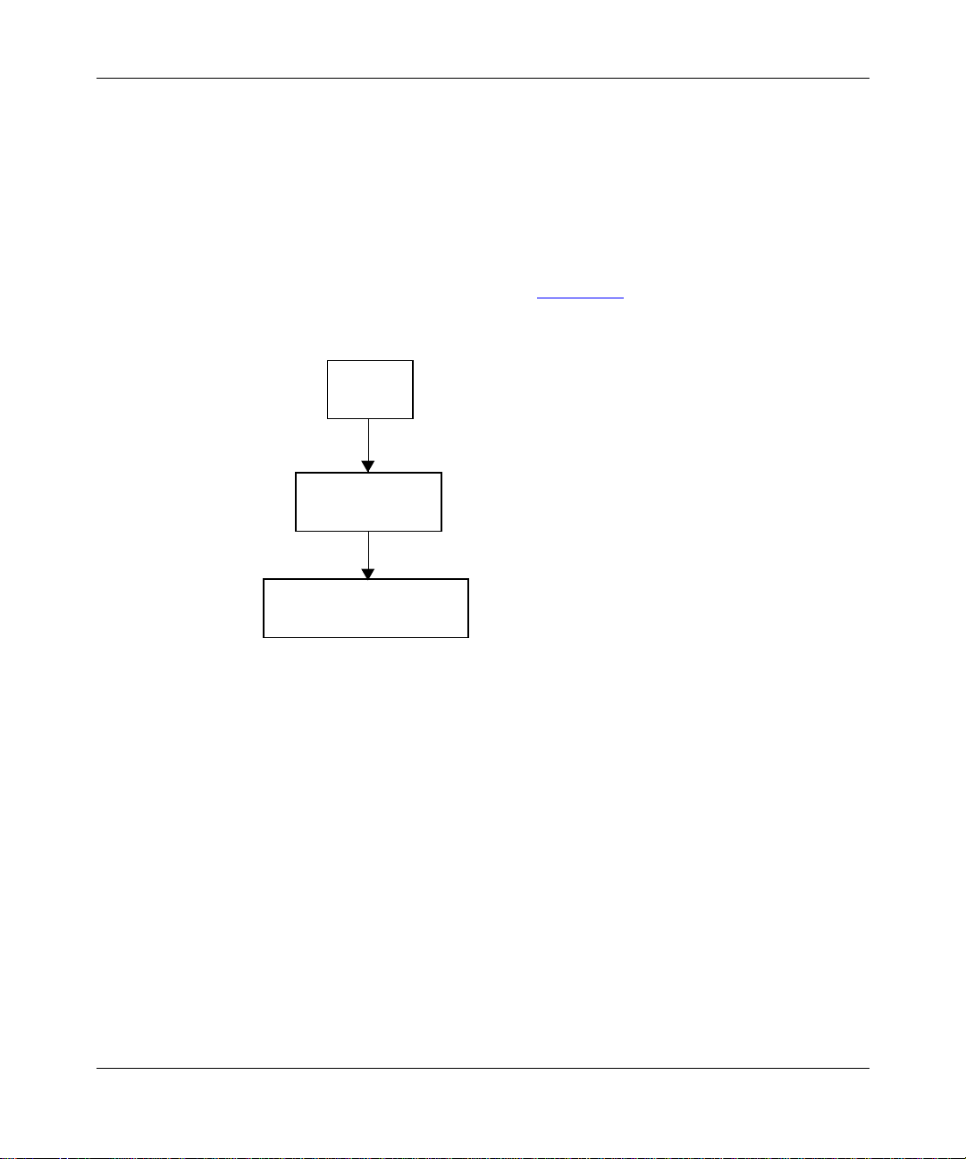
For example, if you conf ig ure an IP interface (address 1.2.3.4, mask 255.0.0.0) on
ethernet/2/1 of a BLN router, the BCC understands its location as
box; ethernet/2/1; ip/1.2.3.4/255.0.0.0 (Figure 1-4.
box
box# ethernet/2/1
ethernet/2/1
ethernet/2/1# ip address 1.2.3.4 mask 255.0.0.0
).
ip/1.2.3.4/255.0.0.0
ip/1.2.3.4/255.0.0.0#
Figure 1-4. Configuring IP and RIP on an Eth ernet Interface
Objects, Classes, and Instances
In BCC terminology, configurabl e entities are referred to as objects of a pa rticular
class, each of which constitutes an insta nce.
•An object is a configur abl e physical or logical entity such as a physical
interface or a pr otocol on an interface. Every configur ab le object belongs to a
specific class that defines its characteristics.
•A class is a template for a configurable object (such as Ethernet or the
protocol IP). When you add a new object to the configuration of a device, the
BCC creates a copy (an instance) of the ap propriate template.
1-6
BCC0017B
303562-A Rev. 00
Page 25

Overview of the BCC
• An instance is an object uniquely identifiable within the total device
configura tion. Each instance is identified by its BCC instance identifier.
BCC Instance Identifier
A BCC instance identif ier uniquely identifies a single instance of an object
configure d on a devic e. The BCC inst ance ID consi sts typi call y of the name of the
object, combined with the values you specify for its required parameters. For
example, the BCC instance ID for an Ethernet interface on a BN platform consists
of
ethernet/
<slot>/<connector>, as in
ethernet/2/1
.
For some objects, the BCC automatically appends an internally generated number
to ensure the uniqueness of the BCC instance ID. For example, the BCC creates
an instance ID for ARP on IP based on the object name (arp), plus the address of
the underlying I P interface (1.2.3.4), plus an internally generate d inte ger, resulting
in an ID such as
arp/1.2.3.4/1
.
In other rare c ases , a con figu rabl e obj ec t m ay also have requi red p aram et er s th at
do not become part of its BCC instance ID. For e xample, the global OSPF object
has a required router-id parameter that doe s not become part of the instance ID.
(Many such required parameters end in “-id,” such as global-id and router-id.)
303562-A Rev. 00
Each object has its own requirements for unique instance identification within the
total devi ce configuration.
Global (Box-Wide) Objects
Global (or box-wide) objects provide services uniformly to all slots of a network
device. Examples include global IP, BGP, TCP, SNMP, FTP, TFTP, and Telnet.
Some protocols, such as IP, RIP, and OSPF, have global and int erface-level
objects.
1-7
Page 26

Using the Bay Command Console (BCC)
Physical Device Objects
The followin g sections provide BCC terms for the physical device.
Box
The BCC uses the term box to identify the chassis for a Bay Networks
nonstackable device. Every box has a type parameter; the value assigned to the
type parameter identifies the type of Bay Networks device. For example, the type
parameter has the value “an” for an AN router and the value “frecn” for a BCN
router with a FRE controller module.
Board
The BCC uses the term board or module to identify any logic or circuit board in a
Bay Networks devic e. Each board typically occupies a slot in a network device.
On some Bay Networks products, one board may contain another board such as an
RMON data collection module (DCM). All board objec ts have a type parameter
that identifies the module type. For example, “qenf” is the value of the type
parameter for a Quad Ethernet with hardware filters module.
1-8
For module desc riptions based on the literal value of the type parameter
Note:
for any board object, see the Release Notes.
Slot
The BCC uses the term slot to identify the location, as well as a physic al and
electrical means, for attaching modules to logic and power connections available
on the device chass is.
• Multislot de vices such as the BLN or BCN router accommodate one system
(SRM-L) or link (interface) module per slot.
• Single-slot de vic es such as the AN, ASN, and ARN router s accommodate one
base module (in slot 1), one or two adapter modu les, and one expansion
module.
303562-A Rev. 00
Page 27

Overview of the BCC
Connector
The BCC uses the term connector to identify the physical and electrical means to
interconnect a networ k device directly or indirectly to a physical layer
transmission medium.
Line
The BCC uses the term line to identify the physical (and in some cases, logical)
circuit identi fied typically by means of a slot, connecto r, interface type (et hernet,
sync, fddi, and so on), and, where applicable, a channel number (such as with
T1/E1 interface types).
Port
The BCC uses the term port to identify an interface object defined by its type (for
example, an Ethernet port) and location (slot and connector) within a network
device. On a network device, a port is also a logical point of termina tion for data
sent or received by a specific protocol or application.
Interface
303562-A Rev. 00
The BCC uses the term interface to identify circuitry and digital logic associated
with the interconnect ion be tween a physical network medium (such as Ethernet)
and a higher-la yer protocol entity (such as IP).
Note:
A logical interfa ce is an addressable entity for originating and
terminating connections across an IP network.
1-9
Page 28

Using the Bay Command Console (BCC)
Parameters
A parameter is an attribute (or property) of a configurable object. Parameters can
be classif ied as one of the following:
• Required
• Derived
• Optional
Required Parameters
For any BCC object, required parameters are a minimum set of parameters for
which the BCC requires you to supply va lue s. For example, the required
parameters of a physical por t are slot and connector.
Derived Parameters
Derived parameters are parameters for which the BCC supplies a value. For
example, a derived parameter of the global OSPF object is router-id. In this c ase,
the BCC deriv es a value for router-id from the address of the first IP interface
configured on the device.
1-10
Optional Parameters
Optional parameters are parameters for which you can specify customized values,
replacing any defa ult values set by the syste m. For example, an optional parameter
of an Ethernet interface is bofl-retries. This parameter normally has a default
value of 5 (5 retries) , but you can change this to another numeric value .
303562-A Rev. 00
Page 29

Chapter 2
Getting Started with the BCC
This chapter provides information about the following topics:
Topic Page
Entering and Exiting the BCC Interface
Displaying Context 2-3
Navigating in Configu ration Mode 2-3
Displaying Configu ration Data 2-8
Using Online Help 2-11
Entering and Exiting the BCC Interface
To access the BCC interface on a Bay Networks router:
Open a Technician Interface session with the target router.
1.
For detailed inf ormation about opening a Technician Interface session, see
Using Technician Interface Software.
Enter the
2.
Manager
your Telnet or console display.
The Manager login allows you to enter any system command and allows
read-write access to the device configuration. The User login allows you to
enter only user-level system command and allows read-only access to the
device configuration.
or
command at the
User
prompt that appears on
Login
2-1
303562-A Rev. 00
2-1
Page 30

Using the Bay Command Console (BCC)
Enter
3.
Router1> bcc
Welcome to Bay Command Console!
* To enter configuration mode, type config
* To list all system commands, type ?
* To exit the BCC, type exit
bcc>
Start BCC configuration mode by entering
4.
bcc> config
box#
at the Technician Interface prompt.
bcc
config
at the
bcc>
prompt.
You enter configuration mode at the roo t (box) level of the BCC conf igura tion
tree. The prom pt ends with a pound symbol (#) if you ha ve read-write
privileges (Manager only), or with a greater than symbol (>) if you have
read-only privileges (Manager or User).
If you enter BCC configuration mode as Manager and want to change your
privilege level for the current session from read-write to read-only, enter
config -read-only
config -read-write
. To change Manager privileges back to read-write, enter
. You cannot change your privi lege level from read-only to
read-write if you logged in as User.
2-2
Caution:
When you enter BCC configuration commands with read-write
privileges, you immediately modify the device configuration.
When you f inish using BCC configuration mode, enter the
5.
command
exit
at any prompt.
box# exit
bcc>
When you finish using the BCC, enter the
6.
command at the
exit
bcc>
prompt.
bcc> exit
Router1>
Exiting the BCC returns you to the Technician Inte rface prompt.
For more detailed information about Technician Interface access, login, or logout
procedures, see Using Technician Interface Software.
303562-A Rev. 00
Page 31

Displaying Context
In configuration mode, the BCC displays a context-sensitive prompt. The prompt
identifies the configured object at your current working location within the
configura tion hierarchy. For example, after logging in to a BLN router as
Manager, then configuring or navigating to the Ethernet interface on slot 2
connector 1, the BCC displays the following prompt:
ethernet/2/1#
To display the complete path from root level to your current lev el in the device
configura tion tree, enter the
Example:
rip/192.168.125.34# pwc
box; ethernet/2/1; ip/192.168.125.34/255.255.255.224; rip/192.168.125.34;
Getting Started with the BCC
(print working context) command.
pwc
The
command displays the BCC insta nce identi fi er of eac h confi gur ed object
pwc
in the path.
Navigating in Configuration Mode
You can navigate from one object to anot her in BCC configuration mode by usi ng:
• The
• Configura tion commands
Navigating with the back Command
In BCC configurat ion mode, use the
leve ls back toward root level. The syntax for the
[<n> ]
back
Entering t he
root lev el.
Example:
rip/192.168.125.34# back
ip/192.168.125.34/255.255.255.224# back
ethernet/2/1#
back
comman d
command with no ar gument mov es you ba ck one level closer to
back
command to move a specif ic number of
back
command is as follows:
back
303562-A Rev. 00
2-3
Page 32

Using the Bay Command Console (BCC)
Entering the
back
command with an integer moves you from your current
working location, back toward root, the number of levels you specify.
Example:
rip/192.168.125.34# back 2
ethernet/2/1#
In this example, the
back 2
command moves you from the current working
location (rip/192.168.125.34), back two levels to ethernet/2/1 (with
ip/192.168.125.34/255.255.255.224 as the intervening level).
Note:
If you enter an integer value that exceeds the actual number of levels
box
back to root (
or
stack
) level, the BCC returns to root level.
Navigating with Configuration Commands
Using BCC configuration commands, you can:
• Move back to a previous level.
• Move back to root level.
• Move forward to the next level.
2-4
• Move from your curre nt level to any other level in the device configuration
tree.
Moving Back One or More Levels
To move from your current working level back one or more lev els closer to root
leve l of the device configurat ion tree, you can enter the full BCC instance ID of
the desired object, as follows:
Example (go back one level):
rip/192.168.125.34# ip/192.168.125.34/255.255.255.224
ip/192.168.125.34/255.255.255.224#
303562-A Rev. 00
Page 33

Getting Started with the BCC
Example (go back two levels):
rip/192.168.155.151# ethernet/2/1
ethernet/2/1#
In the second example , the BCC searches back toward root until it finds a context
or lev el where the object you specified (in this case, et hernet/2/1) exists in the
router configuration tree. The BCC enters the context of this object, and the
prompt displays your new location.
Moving Back to Root Level
You can move back to root level in configuration mode by entering the name of
the object at that le vel.
For an AN, ANH, ARN, or BN router, enter:
ip/1.2.3.4# box
box#
For an ASN or System 5000 router, enter:
ip/1.2.3.4# stack
stack#
Moving Forward One or More Levels
To move from your current working level to the next conf igured level
(Figure 2-1
), enter the BCC instance ID of the desired object , a s foll ows:
Example:
box# ethernet/2/1
ethernet/2/1# ip/1.2.3.4/255.0.0.0
ip/1.2.3.4/255.0.0.0# rip
rip/1.2.3.4#
Notice that a slash charac ter (/) joins the name and any required parameter values
to make a BCC instan ce ID for any configu red object.
303562-A Rev. 00
2-5
Page 34

Using the Bay Command Console (BCC)
box# eth 2/1
(Starting
context)
ethernet/2/1# ip/1.2.3.4/255.0.0.0
box
ethernet/2/1
ip/1.2.3.4/255.0.0.0# rip
Figure 2-1. Mo ving Away fro m Root Level
Moving to Any Context in the Device Configuration
T o navigate to any conf i gured obje ct, yo u can specif y a f ull, o r abso lute, path fr om
box
stack
root (
or
) level at any prompt. When you enter a path, specify the BCC
instance identifier of each object.
ip/1.2.3.4/255.0.0.0
(Ending
context)
rip/1.2.3.4#
rip/1.2.3.4
BCC0014B
2-6
Example:
To move from ip/192.168. 33.66/255.255.255.0 (on ethernet/ 2/1) to rip/1.2.3.4 on
ethernet/2/2 (Figure 2-2
ip/192.168.33.66/255.255.255.0# box;ethernet/2/2;ip/1.2.3.4/255.0.0.0;rip
rip/1.2.3.4#
), enter the following command:
303562-A Rev. 00
Page 35

Getting Started with the BCC
(Starting context)
ethernet/2/1
box
ethernet/2/2
ip/192.168.33.66/255.255.255.0
ip/1.2.3.4/255.0.0.0
(Ending context)
rip
BCC0009B
Figure 2-2. Navigating to an Object in the Configuration
The BCC can automatically search backward (recursively ) t owa rd root level until
it finds a level where the obje ct you specify first in the command line exist s in the
device configuration tree.
Example:
To move from ip/192.168. 33.66/255.255.255.0 on ethernet/2/1 to r ip/1.2.3.4 on
ethernet/2/2 , ent er the following command:
ip/192.168.33.66/255.255.255.0# ethernet/2/2;ip/1.2.3.4/255.0.0.0;rip
rip/1.2.3.4#
303562-A Rev. 00
In this example, the BCC searches backward to find ethe rnet/2/2 (specified first in
the command line), and then moves sequentially to the other locations
(ip/1.2.3.4/255.0.0.0 and rip) specifi ed next in the command line.
2-7
Page 36

Using the Bay Command Console (BCC)
(Starting context)
ethernet/2/1
box
ethernet/2/2
Figure 2-3. Navigating with the BCC Recursive Search Feature
Displaying Configuration Data
To display Bay Netw orks device configuration commands and data , use the
config
comman d.
Displaying the Total Device Configuration
ip/192.168.33.66/255.255.255.0
ip/1.2.3.4/255.0.0.0
(Ending context)
rip
BCC0009C
show
2-8
show config -all
The
command displays the entire device c onfiguration fro m any
BCC prompt. The output of this command describes:
• Existing objects
• Objects that the BCC automatica lly ad ded to the active device configuration
back
• Navigation (
) commands necessary to move to the context of the
previous object configured, or to return to the root level of the active devic e
configuration
303562-A Rev. 00
Page 37

Getting Started with the BCC
Example:
bcc> show config -all
box type freln
board slot 1
type srml
back
board slot 2
type qenf
back
board slot 3
type wffddi2m
. . .
. . .
. . .
ethernet slot 2 connector 1
circuit-name E21-alpha
ip address 192.168.3.4 mask 255.255.255.224
broadcast 192.168.3.5
rip
back
arp
back
back
back
. . .
. . .
. . .
ftp
default-volume 2
back
snmp
community label public
access read-write
manager address 0.0.0.0
back
manager address 192.168.9.9
.
303562-A Rev. 00
Note:
For descriptions of all board type values (such as “qenf”), see the
Release Notes.
2-9
Page 38

Using the Bay Command Console (BCC)
Displaying the Configuration of One Object
To view objects configured within a specific part of the BCC conf iguration tree,
enter the
show config
Example:
To view the configuration of a specific configured object, navigate to the object
and enter the
show config
configured on ethernet/2/1 of a BLN router:
box#
eth 2/1
ethernet/2/1#
ethernet slot 2 connector 1
circuit-name E21-alpha
ip address 192.168.125.34 mask 255.255.255.224
broadcast 192.168.125.32
arp
back
rip
back
back
back
show config
Example:
command or the
lso
command. The following example shows all objects
command.
2-10
You can also enter the
command to vie w any inst ances of obje cts c onf igure d at
lso
your current location in the active device con figuration, as follows:
ip/192.168.155.151/255.255.255.0#
arp/192.168.155.151/1 rip/192.168.155.151
Use the
command if you have no need to display the contents of the current
lso
lso
object in full BCC confi guration syntax.
303562-A Rev. 00
Page 39

Using Online He lp
This section describes how to use BCC online Help.
Help Commands
Table 2-1 lists the commands you use to access BCC online Help.
Table 2-1. BCC Help Commands
Command Help Feature
?
BCC_instance_ID
<
parameter
> <
List the names of all object s and paramet ers you ca n con figur e, and
the system commands you can enter.
> ?Get legal, current, and default values for this paramet er of a
configured object that you can access from your current working
context.
Example:
box#
ethernet/2/1 bofl ?
Current Value: enable
Legal Value: {enable disable}
Default Value: enable
Getting Started with the BCC
command
<
command
<
help
help
>
> <
command
<
?
option
>
?
> Get full details of a specific command.
help co m m a nds
help co m m a nds -more
help editing
help learning-bcc
help
object_name
<
help <
parameter_name
303562-A Rev. 00
> Show usage and paramet er Help for this object.
Display usage Help or next-le vel options for a com ma nd.
Display next-level options for this command or any arguments
available to limit the output fro m this command.
Get an overview of Help-oriented command fe atures.
Display the syntax of all BCC commands in alphabetical order.
Display the syntax and brief command descriptions for all BCC
commands in alphabetical order.
Get Help on how to edit BCC commands and comm and lines.
Get Help on performing common BCC operations.
> Show usage Help for this parameter.
(continued)
2-11
Page 40

Using the Bay Command Console (BCC)
Table 2-1. BCC Help Commands
Command Help Feature
help
<
path
object_name
> <
> Describe parameters of an object outside the current context.
help syntax
help tree
help tree -all
info
object
<
>
?
parameter
<
parameter
<
> Get the current v alue for this paramet er of the current object.
>
?
(continued)
path
(<
> is the sequence of objects between root level and the
desired context.)
Example:
help ip ospf
Hint: Use the
the desired object.
Get Help on symbols used to express BCC command syntax.
List, in hierar chical format, all object s configurable on the current
object.
List, in hierar chical format, all object s configurable on thi s device.
List values currently assigned to parameters of this object.
Get command usage Help and list parameters of an object you can
add or modify from your current location.
Get legal, current, and default values for this paramet er of the
current object.
help tree [-all]
command to determine the path to
2-12
303562-A Rev. 00
Page 41

Help Command Examples
This section provides examples of how you can use the Help commands to get
BCC information.
Listing Objects You Can Configure
Getting Started with the BCC
To list the obje cts you can config ure from the current location, enter the
command.
Example:
ethernet/2/1# help tree
The configuration tree below this context is:
ip
arp
rip
ospf
neighbor
rdisc
igmp
relay
ipx
rip
sap
static-route
adjacent-host
static-service
route-filter
server-network-filter
server-name-filter
auto-neg
You can also use the output of the
help tree [-all
] command to find the
configura tion or navigation path to a specific object.
help tree
303562-A Rev. 00
2-13
Page 42

Using the Bay Command Console (BCC)
Listing Available Objects, Parameters, and System Commands
To list the names of all objects, parameters, and system commands you can enter
from the current context, enter the ? comman d.
Example:
ip/192.168.125.34/255.255.255.224# ?
Sub-Contexts:
arp igmp ospf rdisc rip
Parameters in Current Context:
address cost on
address-resolution end-station-support proxy
all-subnet-broadcast has redirects
assocaddr host-cache-aging state
broadcast mask udp-checksum
cache-size mask-reply
configured-mac-address mtu-discovery
System Commands:
? display ping
back enable pktdump
bccSource exit pop
bconfig format prom
boot getcfg pwc
cd help readexe
clear help-file-version record
clearlog history reset
commit ifconfig restart
compact info rm
config loadmap save
cp log securelogin
cwc logout show
date lso stamp
debug mget stop
delete mlist system
diags more tic
dinfo mset type
dir partition unmount
disable password xmodem
2-14
The “Sub-Context s” section lists the objects that you can add from your current
location in the device configuration tree (Figure 2-4
).
303562-A Rev. 00
Page 43

IP
ARP
RIP OSPF
(Created
automatically
with IP)
Figure 2-4. Objects You Can Configure at the Next Level
Displaying Values Assigned to Parameters
To display the values curr ently assigned to all parameters of the current object,
enter the
info
comman d.
Getting Started with the BCC
IGMP RDISC
BCC0019A
Example:
ip/1.2.3.4/255.0.0.0# info
on ethernet/2/1
state enabled
address 1.2.3.4
mask 255.0.0.0
assocaddr 0.0.0.0
cost 1
broadcast 1.2.3.6
configured-mac-address 0x
mtu-discovery off
mask-reply off
all-subnet-broadcast off
address-resolution arp
proxy off
host-cache-aging cache-off
udp-checksum on
end-station-support off
redirects on
cache-size 128
T o dis pla y the v alue assigned t o a s pecif ic param eter, enter the paramete r name, a s
follows:
ip/1.2.3.4/255.0.0.0# proxy
proxy off
303562-A Rev. 00
2-15
Page 44

Page 45

Chapter 3
Entering Commands and Using Command Files
This chapter provides information about the following topics:
T opic Page
Entering Commands
System Commands 3-5
Configuration C ommand Syntax 3-5
Creating and Using BCC Command Files 3-10
Entering Commands
This section contains information about:
• Using Command Abbreviations
• Recalling Commands
• Editing Command Lines
• Entering Multiple Commands on a Line
• Continuing a Command Line
3-1
303562-A Rev. 00
3-1
Page 46

Using the Bay Command Console (BCC)
Using Command Abbreviations
When you enter BCC commands in configuration mode, you can shorten object
and parameter names (for example, eth = ethernet). You must enter a sufficient
number of characters for the BCC to recognize that name uniquely.
Example:
box#
eth 5/1
ethernet/5/1#
box#
tf
tftp#
back
You can abbreviate system commands; for example, the BCC recognizes sh as
in contexts where there are no other commands, c onfigurable objects, or
show
parameter names that also start with sh.
Recalling Commands
The BCC supports a configura ble command history buffer, from which you can
recall commands recently en tered. The comma nd history buffer contains up to 20
commands by default. You can increase the number of commands in the history
buffer to a maximum of 40 by setting new values for the history parameter of the
console and telnet objects.
3-2
Example:
box#
telnet
telnet#
server#
server#
history 30
server#
box#
console/1#
console/1#
server
history 30
history
box
console portnum 1
history 30
Recall commands from the history buffer as follows:
• To recall the previous command, press the up arro w key, or press [Control]+p.
• To recall the next command, press the down arrow key, or press [Control]+n.
303562-A Rev. 00
Page 47

Editing Command Lines
Table 3-1 describes the keystrokes you can use to edit BCC command lines.
Table 3 -1. Keystrokes for Editing BCC Command Lines
Editing Function Keystrokes
Move the cursor left CONTROL + b
Move the cursor right CONTROL + f
Delete the current line CONTROL + u
Delete the word at the cursor location CONTROL + w
Delete the character at the cursor location CONTROL + d
Move the cursor to the beginning of the line CONTROL + a
Move the cursor to the end of the line CONTROL + e
Toggle insert mode CONTROL + o
Delete previous character BKSP or DEL, or
Interrupt CONTROL + c
Start echo to the screen CONTROL + q
Stop echo to the screen CONTROL + s
Recall previous command CONTROL + p
Recall next command CONTROL + n
Entering Commands and Using Command Files
or left arrow key
or right arrow key
CONTROL + h
or up arrow key
or down arrow key
303562-A Rev. 00
For example, use the up arrow key (or [Control] + p) to retrieve your last input,
then use other control-key combinations to edit the command line as needed.
3-3
Page 48

Using the Bay Command Console (BCC)
Entering Multiple Commands on a Line
To enter multiple commands on the same line, type a semicol on (;) wherever you
would press Return to terminate a command.
Example:
Configure ethernet/2/1 from root, then configure ip/1.2.3.4/255.0.0.0 on
ethernet/2/1 and RIP on ip/1.2.3.4/255.0.0.0, as follo ws:
box#
ethernet/2/1;ip 1.2.3.4/255.0.0.0;rip
rip/1.2.3.4#
Continuing a Command Line
You can continue a command line by enter ing a backslash ( \ ) char acter at the end
of the curre nt text line. The BCC treats characters on the next ph ysical line as part
of the same BCC logical command line.
You must immediately follow t he backslas h ( \ ) with a newline (Return) character.
The BCC treats these two characters and any trailing spaces as if they were
exactly one space. Until you press Return without a preceding backslash ( \ )
character, the BCC replaces the pound symbol (#) in the context-sensitive prompt
with an underscore ( _ ) character.
3-4
Example:
ip/1.2.3.4/255.0.0.0#
ip/1.2 .3 .4
ip/1.2.3.4
ip/1.2.3.4
ip/1.2.3.4
/255.0.0.0
/255.0.0.0
/255.0.0.0
/255.0.0.0
cost 2 \
mask-reply on \
_
proxy on \
_
aging cache-on
_
#
Some command symbols normally used in pairs to denote the beginning and the
end of a set of data also produce the continuation ( underscore) prompt , inclu ding
braces ({ }), brackets ([ ]), and quotation marks (“ ”).
Example:
box#
{ ...
box_
...}
box#
303562-A Rev. 00
Page 49

Entering Commands and Using Command Files
If you inadvertently type one of the opening symbols and see an
Note:
underscore prompt, just type the corresponding closing symbol to restore the
normal (#) prompt in BCC configuration mode.
System Commands
The BCC supports all syst em commands de scribed in Appendix A. For Help on a
specific command, enter
prompt.
<command> (for example,
help
Configuration Command Syntax
This section describe s BCC conf igura tion commands and the syntax requir ements
for those commands. This section also describes how to enter BCC configuration
commands using the following formats:
• Basic (full) syntax
help save
) at any BCC
• Default syntax
• Abbreviate d syntax
Caution:
configuration.
Configuration commands make real-time changes to the device
Command Syntax Requirements
BCC syntax consists of object names, par ameter names and values, and variou s
types of punctuation.
• All object and parameter names appear as one word (hyphenated where
necessary) in the BCC command line.
• Parameter s have either a single value or multiple values enclosed in braces
{x y z} in the command line. You can accept the defa ult value or supply a
value for each para mete r associated with a configurable object.
• Parameters and their values must appear as a pair in the same command line.
303562-A Rev. 00
3-5
Page 50

Using the Bay Command Console (BCC)
• Syntax for speci fying the object you want to configure may vary ac cording to
the number of slots in the Bay Networks device to which you are connected.
Appendix D
lists the syntax for specifying the physical location of a module
for each Bay Networks de vice that the BCC supports.
• If you enter the name of an object without values for its required parameters,
or with values ina ppropriate for its required parameters , the BCC returns
usage Help, as shown in the following example:
box# ethernet
Required parameter "slot" was not specified for ethernet.
Usage: "ethernet slot <value> connector <value>"
Or: "ethernet <slot>/<connector>
Using Basic (Full) Syntax
The basic, or full, syntax for BCC commands consists of the following required
and optional elements:
{
<object-name>
<parameter> <value>
}
{
<required_parameter> <value>
...
<parameter> <value>
... } ...
The BCC requires input for any elements enclosed by braces ({ }).
{<object-name>} is the name of an object you want to configure (for example,
).
ip
The BCC assumes that an object you specify is new (and will create it) if it is not
in the current configuration. If an object you specify already exists in the current
configura tion, the BCC assumes that you want to modify that object.
{<required_paramete r> <value>}
is any parameter-value pa ir required to
uniquely identify an obj ect you specify in a BCC command line. An object may
have one or more required parameters.
For example , the full synt ax for configuring an Ethernet in terf ace on an AN/ANH,
ARN, or BN router is:
ethernet slot
<slot_no.>
connector
<connector_no.>
On an ASN or System 5000 router, the ful l syntax is:
ethernet slot
<slot_no.>
module
<module_no.>
connector
<connector_no.>
3-6
303562-A Rev. 00
Page 51

You cannot change the value of a parameter used by the BCC to create
Note:
an instance identif ier. For example, you cannot modify the address value
assigned to an IP interface.To change the value of any required parameter, you
must delete the associated object, and then add it back into the device
configura tion with new required value s.
<parameter> <value >] is any pa rameter - va lue pair you ca n optiona lly customize
[
for an object you specify in a BCC command line.
Using Default Syntax
Using default synta x, you do not need to enter the name of a required parameter;
you enter only its value at the proper location in the command line.
For example, the default syntax for configuring an Ethernet interface on an
AN/ANH, ARN, or BN router is:
Entering Commands and Using Command Files
ethernet
<slot>/<connector>
The following com mands are equivalent.
Using full syntax:
box#
ethernet slot 2 connector 1
ethernet/2/1#
Using default syntax:
box#
ethern et 2/ 1
ethern et /2/ 1#
Using Abbreviated Syntax
You can abbreviate BCC configuration commands as follows:
Example:
box#
eth 2/1
This command is the same as the following two commands:
box#
ethernet slot 2 connector 1
box#
ethernet 2/1
303562-A Rev. 00
3-7
Page 52

Using the Bay Command Console (BCC)
If you press Return before entering a sufficient number of characters for the BCC
to recognize the name of the object or parameter you want to configure, the BCC
returns an error message .
Example:
box# e
ambiguous command name "e": enable eof error ethernet eval exit expr
The BCC returns a list of all the commands available in the current context that
start with the letter “e.” Choose one command from the list, and enter enough
characters for the BCC to recognize that command when you press Return.
You cannot abbreviate BCC instance identifiers.
Specifying Parameter Values
You must specify each paramet er v al ue in the f orm of a paramete r -v alue pair. Each
pair is a command argument perta ining to the object named first in the command
line.
For example, the following command changes the BOFL timeout interval to 4
seconds on ethernet/1 /1:
3-8
ethern et/ 1/ 1 bo fl-timeo ut 4
box#
bofl-timeout 4
is the p a r ameter-value p a i r.
Required, Derived, and Other Parameters
The BCC indicates when parameter values are required (you must supply a value)
or derived (the BCC supplies a va lue). For all other parameters, the BCC supplies
a default v al ue that you can change.
Specifying Multiple Parameter-Value Pairs
You can specify parameter values as follows:
• Enter an object name and one parameter-value pair per command line.
• Enter an object name and multiple parameter-value pairs (each pair separated
by a space) on the same command line.
303562-A Rev. 00
Page 53

Entering Commands and Using Command Files
Example:
In the follo wing e xa mple, you spe cify one paramete r -v alue pair on eac h command
line.
box#
ethern et 2/ 1
ethernet 2/1#
ethernet 2/1#
ethernet 2/1#
ethernet 2/1#
bofl-re tr ie s 6
bofl-ti me ou t 7
hardware-filter enabled
Example:
In the following e xample, you specify multiple parameter-value pairs on each
command line.
ethernet 2/1#
ip.1.2.3.4/255.255.255.0#
ospf/1.2.3.4#
ip address 1.2.3.4 mask 255.255.255.0 redirects off
ospf area 2.3.4.54 hello-interval 5
303562-A Rev. 00
3-9
Page 54

Using the Bay Command Console (BCC)
Disabling, Reenabling, and Deleting a Configured Object
Table 3-2 lists the commands you can use to disable, reenable, and delete any
configure d object. To use these commands, you must be in configuration mode
with read-write privileges.
Table 3-2. BCC Commands
Command Function
disable
enable
delete
Change the state of a configured object from enabl ed to di sabled, as foll ows:
ip/1.2.3.4/255.0.0.0# disable
You can accomplish the same change by assigning the value “di sabled” to the state
parameter of an obj ect that you want to disab le.
Change the state of a configured object from disabled to enabled, as follows:
ip/1.2.3.4/255.0.0.0# enable
You can accomplish the same change by assigning the value “enabled” to the state
parameter of an obj ect that you want to reenable.
Delete the obj ect i denti fied in th e BCC co nte xt-se nsi tiv e prompt . For e xam ple, the following
command deletes an IP interface (address 1.2.3.4):
ip/1.2.3.4/255.0.0.0# delete
CAUTION:
automatically delete any branches configured on that object. For example, if you delete an
IP interface, the BCC deletes any prot ocols (such as RIP, ARP, or OSPF) configured on
that interface.
Deleting an object at one level of the configuration tree causes the BCC to
Creating and Using BCC Command Files
You can save BCC commands to an ASCII file, edit the file, add comments, and
then use the
source
configura tion. The following sections describe how to complete these tasks.
command to read the file into the device’s active
3-10
303562-A Rev. 00
Page 55

Saving Commands to a File
If you log in to a Bay Networks router from a PC or workstation using Te lnet or
terminal emulation, you can use the native capabilities of the PC or workstation
to:
Entering Commands and Using Command Files
• Save the out put of a
show config
• Save a sequence of manually e ntered BCC commands to an ASCII file.
You can also use an ASCII text editor on a work station to create a file from which
the BCC can read configuration and system commands.
You can also sa ve the output of the
Note:
text fi le on the router by entering
<volume>:<filename>
at any BCC prompt.
show config [-all] -file
Adding Comments to a Command File
You can use a text editor (such as vi on a UNIX workstation) to add descriptive
comments to a BCC command file. Enter comments in the following format:
box#
or
box#
box#
<command>
#comment
<command>
;# comment
command to an ASCII file.
show config
command to an ASCII
303562-A Rev. 00
Example:
box#
board slot 1 type andse;# 192.168.47.129 192.168.47.21
When you fini sh edit ing the f ile , save it on your w orksta tion or PC. The commen ts
are for reference only. Comments do not appear in the output of any
show config
command.
3-11
Page 56

Using the Bay Command Console (BCC)
Entering Configuration Commands from a File
When you are logged in to the BCC as Manager, you can use the
source
command in configura tion mode to read BCC configuration and navigation
commands from a designated ASCII source file into the active device
configura tion.
Caution:
The
source
command makes immediate changes to the active
device configuration.
The
source
command merges new configuration data from a file with existing
data in device memory. If the file you specify contains configuration commands
pertaining to obje cts alr eady def ine d on the de vic e, those c ommands ov erwrit e the
current configuration.
If the BCC detects an error in the source file, it stops re ading c ommands
Note:
into the device configuration.
Syntax for the
source
<volume>:<filename>
source
command is as follows:
Saving the Active Configuration as a Bootable Binary File
When you finish using BCC commands to modify an existing configuration, save
the new configuration to a file on an NVFS (flash) volume. (At boot time, the
router loses any configurat ion changes not previously saved to an NVFS volume.)
The followin g command sa ves config as a bootable binary file on a volume you
specify:
bcc> save config <
3-12
volume
>:<
filename
>
303562-A Rev. 00
Page 57

Chapter 4
Tutorial: Configuring a Network Device
This chapter pro vid es a t utorial th at guide s you through t he initi al co nfi gurat ion of
a Bay Networks devi ce using the BCC. It inc ludes the following sections:
Topic Page
Creating and Modifying a Device Configuration
Disabling a Configured Object 4-15
Enabling a Configured Object 4-16
Deleting a Configured Object 4-17
Creating and Modifying a Device Configuration
You configure a Bay Networks device by defining a set of objects, starting at the
root level of the device’s configuration hierarchy. Each object has a set of
parameters with va lues set either by you or by the device software.
Following is a typical BCC configuration sequence.
1.
Open a Technician Interface session and start the BCC interface.
2.
Start BCC configuration mode.
3.
Use BCC configurati on commands to create new objects in the device
configura tion and modify default v al ues for p arameters of each object to meet
the requirements of your network.
4.
Enable any box-wide prot oco ls not enabled automatically by the BCC, for
example, TFTP and Telnet Server.
5.
Use the
on the device.
command to save your configuration as a bootable (binary) file
save
4-1
303562-A Rev. 00
6.
Exit BCC configuration mode, exit the BCC to the Technician Interface, and
log out of the device.
4-1
Page 58

Using the Bay Command Console (BCC)
You may find it helpfu l to f irst dia gram what you wa nt to conf igur e in terms of t he
BCC configuration tree or hierarchy for the device. Refer to the following sample
router configuration.
Sample Router Configuration
The follo wing e xampl e sho ws a sequence of comman ds you can use to conf igur e a
BCN router on a network. You first c omplete the physical installation of the
router, then boot the router using the image (bn.exe ) and the minimum
configura tion file (ti.cfg).
This example creates the following objects in the total router con f iguration
(Figure 4-1
):
• IP (global)
-- ARP (global) on IP
-- RIP (global) on IP
• SNMP (global)
-- Community “public” on SNMP
- Manager (address 0.0.0.0) on community “public”
4-2
• FTP (global)
• TFTP (global)
• T elnet (global)
-- Server (global) on Telnet
• Quad Ethernet interface in slot 13
-- IP in te rface (addr es s 192.168.133.114) on Ethernet connector 1
- ARP on IP interface 192.168.133.114
- RIP on IP interface 192.168.133.114
• Serial interface in slot 5
• Dual token ring interface in slot 9
• FDDI interface in slot 11
303562-A Rev. 00
Page 59

Tutorial: Configuring a Network Device
box
ip snmp
telnet
serial/5/1
token-ring /9/1
token-ring /9/2
ethernet/13/2
ethernet/13/1
ip
ethernet/13/3
riparp
fddi/11/1
ethernet/13/4
server
Global Services
Figure 4-1. Sample BCC Configuration (BCN Router)
After you creat e a diagram of the device configurat ion t ree, co nfigure the d evice
using a cycle of BCC confi guration commands similar to those shown in
Figure 4-2.
riparp
tftp
community “p ublic”
manager 0.0.0.0
ftp
303562-A Rev. 00
4-3
Page 60

Using the Bay Command Console (BCC)
START/
CONTINUE
Enter the name of
any changed parameter
to verify its new
assigned value.
Where necessary, enter
the name of any parameter
with a new value, for example:
bofl disabled.
Enter info to check
parameter values assigned
to the new (current) object.
Current
prompt
Enter ? for a list of objects and
parameters configurable in this
context of the configuration tree.
Usage Help returned?
Reenter the command in the format
shown in the usage Help message.
Figure 4-2. Typical BCC Configuration Cycle
Enter the name of the next
object you want to configure.
(for example, ethernet).
BCC0013B
4-4
303562-A Rev. 00
Page 61

Tutorial: Configuring a Network Device
To create the sample configuration shown in Figure 4-1 using BCC commands,
proceed as follows:
Log on to the router as Manager, so that you can modify the device
1.
configuration.
Bay Networks, Inc. and its Licensors.
Copyright 1992, 1993, 1994, 1995, 1996, 1997, 1998. All rights reserved.
Login: Manager
Mounting new volume...
Device label:
Directory: 2:
New Present Working Directory: 2:
Welcome to the Backbone Technician Interface
Router1>
Start the BCC by ent eri n g
2.
Router1> bcc
Welcome to Bay Command Console!
* To enter configuration mode, type config
* To list all system commands, type ?
* To exit the BCC, type exit
bcc>
Enter BCC configuration mode by entering
3.
bcc> config
box#
at the Technician Interface prompt.
bcc
config
.
303562-A Rev. 00
4-5
Page 62

Using the Bay Command Console (BCC)
Check the ha rdwa re con figurati o n of the rou ter.
4.
box# show config
box type frecn
board slot 5
type sync
back
board slot 7
type srml
back
board slot 9
type dtok
back
board slot 11
type wffddi2m
back
board slot 13
type qenf
back
console portnum 1
prompt {"%slot%:"}
auto-manager-script automgr.bat
auto-user-script autouser.bat
back
back
box#
Note how output of the
navigat ion (
(BCN router with a FRE-2 controller)
(Serial link module in slot 5)
(System resource module in slot 7)
(Dual token ring link module in slot 9)
(Multimode FDDI link module in slot 11)
(Quad Ethernet with filters in slot 13)
(console device on port 1)
show config
back
) commands. If you sav e this outpu t to a f ile, y ou can reent er
command automatically includes
the commands automaticall y using the BCC
“Entering Configuration Commands from a File
source
comman d. (See
” on page 3-12.)
4-6
For descriptions of the values of the board type parameter, see the Release
Notes.
Choose a port (interface type, slot , and connector) for the initial IP
5.
interface to the router.
box# ethernet slot 13 connector 1
ethernet/13/1#
303562-A Rev. 00
Page 63

Tutorial: Configuring a Network Device
Check what you ca n configure (s ub -co n tex ts and pa ra meters) at this
6.
level.
ethernet/13/1# ?
Sub-Contexts:
ip ipx
Parameters in Current Context:
bofl circuit-name on
bofl-number connector receive-queue-length
bofl-retries hardware-filter slot
bofl-timeout has state
bofl-tmo-divisor name transmit-queue-length
System Commands:
? delete mkdir reset
attribute diags mlist restart
back dinfo more rm
boot dir mount rmdir
cd disable mset save
clear enable partition securelogin
clearlog exit password show
commit format ping source
compact help pktdump stamp
config history pop stop
context loadmap prom system
cp log pwc tic
cwc logout readexe unmount
date lso reconfig xmodem
debug mget record
ethernet/13/1#
303562-A Rev. 00
Based on the “Sub-Contexts” list, you can add ip (interface IP) or
ipx
(interface IPX ) to this Ethernet port. The list of configurable objects depen ds
on the board type described in the current prompt. For example, 100BASE-T
modules additionally allow you to configure an “autoneg” (autonegotiation)
object at this le vel.
You can also modify the values currently assigned to “Parameters in Current
Context” (parameters of ethernet/13/1), shown above.
The “System Commands” list alwa ys appears along with informa tion about
configurable objects and parameters.
4-7
Page 64

Using the Bay Command Console (BCC)
Add IP (address 192.168.133.114) to ethernet/13/1.
7.
ethernet/13/1# ip 192.168.133.114
Usage: "ip address <value> mask <value>"
Or: "ip <address>/<mask>"
Required parameter "mask" was not specified for ip.
The error message appears because the BCC requires you to enter a mask
value whenever you create an IP interface. Because the first octet of the
address is 192 (0xC0), this is a Class C address, requiring the first 3 octets to
be the network portion of the interface address. You can express the
corresponding mask v alue as either 255.255.255.0 (using dotted-decimal
notation) or 24 (the number of bits making up the network portion of the IP
interface address), as follows:
ethernet/13/1# ip 192.168.133.114/24
ip/192.168.133.114/255.255.255.0#
The BCC conve rts the integer representing the number of mask bits into a
dotted-decimal mask value, as shown in the last prompt.
Check the values currently assigned to parameters of IP on this interface.
8.
ip/192.168.133.114/255.255.255.0# info
state enabled
address 192.168.133.114
mask 255.255.255.0
assocaddr 0.0.0.0
cost 1
broadcast 0.0.0.0
configured-mac-address 0x
mtu-discovery off
mask-reply off
all-subnet-broadcast off
address-resolution arp
proxy off
host-cache-aging cache-off
udp-checksum on
end-station-support off
redirects on
cache-size 128
4-8
303562-A Rev. 00
Page 65

Tutorial: Configuring a Network Device
Change the subnet mask to 255.255.255.224.
9.
ip/192.168.133.114/255.255.255.0# mask 255.255.255.224
"mask" parameter may not be modified
ip/192.168.133.114/255.255.255.0#
You cannot modify any paramet er v al ues includ ed in the BCC instanc e I D of a
configure d object, in this case, ip/192.168.133 .114/255.255.255.0. To change
the value of any parameter that is part of a BCC instance ID, you must first
delete the obje ct, the n re-cre at e it with the desired parameter values. In thi s
case, you must delete the IP interface and then re-create it on ethernet/13/1,
using the mask value of 255.255.255.224, as follows:
ip/192.168.133.114/255.255.255.0# delete
ethernet/13/1# ip 192.168.133.114/255.255.255.224
ip/192.168.133.114/255.255.255.224#
Check to see what you can configure at this level.
10.
ip/192.168.133.114/255.255.255.224# ?
Sub-Contexts:
arp igmp ospf rdisc rip
Parameters in Current Context:
address cost name
address-resolution end-station-support on
all-subnet-broadcast has proxy
assocaddr host-cache-aging redirects
broadcast mask state
cache-size mask-reply udp-checksum
configured-mac-address mtu-discovery
303562-A Rev. 00
System Commands:
. . .
. . .
. . .
You can modify values currently assigned to parameters of
ip/192.168.133.114/255.255.255.224, or you can add RIP, OSPF, Router
Discovery, or IGMP to this interface.
Add RIP as the routing protocol ( by default, RIP1) on this interface.
11.
ip/192.168.133.114/255.255.255.224# rip
rip/192.168.133.114#
4-9
Page 66

Using the Bay Command Console (BCC)
Return to root (box) level to configur e global system services.
12.
rip/192.168.133.114# box
box#
Check which global services and interfaces you can configure at this level.
13.
box# ?
Sub-Contexts:
atm fddi ipx serial virtual
backup-pool ftp isdn-switch snmp
board hssi mce1 telnet
console http mct1 tftp
ethernet ip ntp token-ring
Parameters in Current Context:
build-date description location system-name
build-version has mib-counters type
contact help-file-name on uptime
System Commands:
. . .
. . .
. . .
You can add any of the following global services (af fecting all slots): HTTP,
IP, IPX, FTP, NTP, SNMP, Telnet, and TFTP.
4-10
You can add any of the following interfaces: ATM, Ethernet, FDDI, HSSI,
serial, token ring, or virtual.
You can view the configuration of a board in any slot, but you cannot modify
the parameters of any board obje ct.
List the objects already configured at box level.
14.
box# lso
board/11 board/5 board/9 ethernet/13/1
board/13 board/7 console/1 ip
box#
When you added the first instance of IP to the box (ip/192.168.133.114/
255.255.255.224), the BCC automatically created the global IP object at box
leve l.
Add SNMP to the de vice.
15.
box# snmp
snmp#
303562-A Rev. 00
Page 67

Tutorial: Configuring a Network Device
Check what you ca n configure nex t at this level.
16.
snmp# ?
Sub-Contexts:
community trap-entity trap-event
Parameters in Current Context:
authentication-traps lock-timeout state
has name type-of-service
lock on
lock-address scope-delimiter
System Commands:
. . .
. . .
. . .
You can modify values currently assigned to parameters of SNMP, and you
can add a community, define a trap entity, or define a trap event.
View the parameter definitions using the BCC
17.
snmp# help snmp
snmp Parameters:
_________________________________________________________________
state
Indicates the administrative state of this object (enabled or
disabled).
authentication-traps
Sends trap for sets from false Mgr or Community.
lock
Allows the locking mechanism to be disabled.
lock-address
Allows the lock address to be cleared.
lock-timeout
. . .
. . .
. . .
Define the SNMP community “public.”
18.
snmp# community public
community/public#
help
command.
303562-A Rev. 00
4-11
Page 68

Using the Bay Command Console (BCC)
Check the values currently assigned to parameters of this SNMP
19.
community.
community/public# info
on snmp
label public
access read-only
scope-type {}
To allow network management applications (such as Site Manager) to
20.
modify the device configuration, change the value of the access parameter
to read-write
community/public# access read-write
community/public#
Define an SNMP manager for the router.
21.
community/public# manager
Usage: "manager address <value>"
Or: "manager <address>"
Required parameter "address" was not specified for manager.
.
The BCC error message indicates what you left out and automatically
provides usage Help on how to configure an SNMP manager.
T ry again to add the manager, this time supplying a value for its required
22.
parameter, address. (You must enter a value for a required parameter,
but you can omit the name of the parameter.)
4-12
community/public# manager 0.0.0.0
manager/public/0.0.0.0#
Enable the Telnet s erve r entity o n the router.
23.
manager/public/0.0.0.0# telnet
telnet# server
server#
Add TFTP services globally to the router.
24.
server# tftp
tftp#
The BCC automatically searches back (toward root) to find the parent c ontext
suitable for Telnet and TFTP (in this case, box). The BCC then adds Telnet
and TFTP to the device configuration. Note the new (
tftp#
) prompt.
303562-A Rev. 00
Page 69

Tutorial: Configuring a Network Device
Check the values currently assigned to parameters of TFTP.
25.
tftp# info
on box
state enabled
default-volume 2
retry-timeout 5
close-timeout 25
retry-count 5
Change the de fa ul t volum e nu m be r for TFTP to 5.
26.
tftp# def 5
tftp#
Verify the change to the default volume number .
27.
tftp# def
default-volume 5
Add FTP globally to the router.
28.
tftp# ftp
ftp#
The BCC automatically searches back (toward root) to find the parent c ontext
suitable for FTP (in this case, box). The BCC then adds FTP to the device
configura tion. Note the new (
ftp#
) prompt.
303562-A Rev. 00
Check the definiti ons for para meters of FTP.
29.
ftp# help ftp
ftp Parameters:
_________________________________________________________________
on
Identifies the parent(s) of this object.
state
Indicates the administrative state of this object (enabled or
disabled).
default-volume
Specifies the default volume where transferred files are
written/retrieved.
. . .
. . .
. . .
4-13
Page 70

Using the Bay Command Console (BCC)
Check value s cu rrent ly assigned to parameters of FTP.
30.
ftp# info
on box
state enabled
default-volume 2
login-retries 3
idle-timeout 900
max-sessions 3
tcp-window-size 60000
Change the de fa ul t volum e nu m be r to 5.
31.
ftp# def 5
ftp#
Verify the change to the default volume number .
32.
ftp# def
default-volume 5
Recheck the total device configuration.
33.
ftp# show config -all
box type frecn
board slot 5
type sync
back
board slot 7
type srml
back
board slot 9
type dtok
back
board slot 11
type wffddi2m
back
board slot 13
type qenf
back
console portnum 1
prompt {"%slot%:"}
auto-manager-script automgr.bat
auto-user-script autouser.bat
back
ethernet slot 13 connector 1
circuit-name E131
ip address 192.168.133.114 mask 255.255.255.224
. . .
. . .
(remaining configuration not shown here)
4-14
Return to root level.
34.
ftp# box
box#
303562-A Rev. 00
Page 71

Tutorial: Configuring a Network Device
Save the f ile using a name other than
35.
until you can test the
config
configuration.
box# save config startup.cfg
Test the intial IP i nte rfa ce .
36.
box# ping 192.168.133.114
IP ping: 192.168.133.114 is alive (size = 16 bytes)
Ensure that the initial IP interface connects to another device on the
37.
network.
box# ping 192.168.133.97
IP ping: 192.168.133.97 is alive (size = 16 bytes)
When you finish configuring the router, exit configuration mode.
38.
box# exit
bcc>
Exit the BCC, which returns you to the Technician Interface prompt.
39.
bcc> exit
Router1>
Enter the
40.
logout
command to close your console or Telnet session with
the router.
Router1> logout
Disabling a Configured Object
In most cases, the BCC automatically enable s objects that you add to the device
configura tion. However, you can disable an object to manage or troubl es hoot the
device. Here is a BN router example of how to disable an object (rip) on
ip/1.2.3.4/255.0.0.0:
Specify the configuration context for the object you want to disable.
1.
ethernet/2/1;ip/1.2.3.4/255.0.0.0;rip
box#
rip/1.2.3.4#
Disable RIP.
2.
disable
state
303562-A Rev. 00
rip/1.2.3.4#
rip/1.2.3.4#
Verify that y ou disabled RIP.
3.
rip/1.2.3.4#
state disabled
rip/1.2.3.4#
4-15
Page 72

Using the Bay Command Console (BCC)
You can also disable an object from its parent context, using the following syntax:
disable
<BCC_instance_identifier>
Example
ip/1.2.3.4/255.0.0.0#
ip/1.2.3.4/255.0.0.0#
disable rip/1. 2.3.4
Using this method, you remain in the current context after disabling the branch
object.
Enabling a Configured Object
If you disable a configured object, you can use the BCC
reenable that obj ect. Here is a BN router example of how to en able an object (rip)
previou sly disabled on ip/1.2.3.4/255.0.0.0:
Specify the configura ti on co n tex t for RIP.
1.
box#
ethernet/2/1;ip/1.2.3.4/255.0.0.0;rip
rip/1.2.3.4#
Reenable RIP.
2.
rip/1.2.3.4#
rip/1.2.3.4#
Verify that you reenabled RIP.
3.
enable
enable
command to
4-16
rip/1.2.3.4#
state enabled
rip/1.2.3.4#
state
You can also enable an object from its parent context, using the following syntax:
enable
<BCC_instance_identifier>
Example
ip/1.2.3.4/255.0.0.0#
ip/1.2.3.4/255.0.0.0#
enable ri p/ 1. 2. 3.4
Using this method, you remain in the current context after enabling the branch
object.
303562-A Rev. 00
Page 73

Deleting a Configured Object
Because of the tree hierarchy, objects on higher branches of the tree depend on t he
state (and existe nc e) of objects closer to the root of the tree. Deleting an object
also deletes anything configured on that object.
Tutorial: Configuring a Network Device
Caution:
Before using the BCC to delete an interface, make sure that you did
not use Site Manager to configure it with a protocol that the BCC does not
recognize. If you did, use Site Manager to delete the interface.
Here is a BN router example of how to delete an IP interface from the active
device configuration:
Navigate to the objec t y ou want to delete.
1.
box# ethernet/13/1
ethernet/13/1# ip/192.168.133.114/255.255.255.224
ip/192.168.133.114/255.255.255.224#
List all objec ts con figured on the cu rrent o bj ect.
2.
ip/192.168.133.114/255.255.255.224# lso
arp/192.168.133.114/1 rip/192.168.133.114
Delete the object.
3.
ip/192.168.133.114/255.255.255.224# delete
ethernet/13/1#
Verify that you deleted the object.
4.
ethernet/13/1# lso
(no objects listed)
Note that ip/192.168.133.114/255.255.255.224 no longer appears in the list of
objects configured on ethernet/13/1. With a single
command, the BCC
delete
automatically del et ed the branch objects (arp/192.168.133. 114/1 a nd
rip/192.168.1 33.114) configured on ip/192.168.133.114/255.255.255.224.
303562-A Rev. 00
You can also delete an object from its parent context, using the following syntax:
delete
<BCC_instance_identifier>
Example:
ip/1.2.3.4/255.0.0.0#
ip/1.2.3.4/255.0.0.0#
delete ri p/ 1. 2. 3.4
4-17
Page 74

Using the Bay Command Console (BCC)
Using this method, you remain in the current context after deleting the branch
object.
4-18
303562-A Rev. 00
Page 75

Appendix A
System Commands
The BCC supports the system commands listed in Table A-1.
For more detailed information about any of these commands:
• Enter
• Refer to the guide Using Technician In terface Software .
<command> at any BCC prompt (for example,
help
help save
).
303562-A Rev. 00
A-1
Page 76

Using the Bay Command Console (BCC)
Table A-1. System Commands
Command Purpose
Login/Access
Privileges
Manager User
?
<command>
<object>
<parameter>
<object> <parameter>
!
<n>
[
(Technici an Interface only)
back
[
(BCC configuration mode only)
bcc
boot
[ {
vol>:<config_name>
{ <
cd
<vol>
[
clear
clearlog
commit
?
?
?
?
]
<n>
]
<vol>:<image_name>
| - } ]
<directory>
:][
<subcommands> <flags>
<slot_ID>
[
] Set or dis pla y the cu rrent w orking v olume
] Clear all pre vious e vent s from the system
| - }
List the names of objects, parameters,
and system commands you can enter
next.
Displa y syntax usage Help for
<command>.
List parameter s of an obj ect you can
access or configure from your current
level in the device configuration tree.
List the current, default, and legal values
for this parameter of the current object.
List the current, default, and legal values
for the specified parameter of this object.
Repeat the last command, or repeat the
last command
Move your current working location back
<n>
levels closer to the root level of the
BCC configuration tree.
Start the BCC from the Technician
Interface prompt.
Reboot the system.
and directory.
Clear specific device informati on, such
as IP and RIP data.
even t lo g.
Commit (make effective) new values that
you assign to MIB att rib utes.
<n>
times.
✔✔
✔✔
✔✔
✔✔
✔
✔✔
✔
✔
✔
(continued)
A-2
303562-A Rev. 00
Page 77

System Commands
Table A-1. System Commands
Command Purpose
compact
config [-read-write|-read-only
(BCC only)
copy
(Technici an Interface only)
cp
(BCC only)
date
[{+|-}
delete
<volume>
<vol>:<filename1> <vol>:<filename2>
<vol>:<filename1> <vol>:<filename2>
<mm/dd/yy>
[
<hh:mm>
<filename> <volume>
: Compact existing files into a contiguous
]
<hh:mm:ss>
] [
]
]
(continued)
address space on a volume, and
compact all unused space into a single
contiguous block of free space for new
files on the same volume.
Enter BCC configuration m ode. If you
logged on as Manager, you have
read-write access to the device
configurat ion; if you logged on as User,
you hav e read-only access, which allows
you to displa y the existing conf iguration,
but prevents you from changing the
configurat ion.
If you enter BCC configuration mode as
Manager and want to change your
privilege level for the current session
from read-write to read-only, enter
config -read-only
privileges back to read-write, enter
config -read-wri te
Copy the contents of the first file to the
second file.
Copy the contents of the first file to the
second file.
Display or update the system time and
time zone.
Delete the file from the specified volume.
Login/Access
Privileges
Manager User
✔
✔✔
. To change Manager
.
✔
✔
✔✔
✔
(Technici an Interface only; see rm for BCC
equivalent)
303562-A Rev. 00
(continued)
A-3
Page 78

Using the Bay Command Console (BCC)
Table A-1. System Commands
Command Purpose
delete
(BCC configuration read-write mode only)
diags
dinfo
dir
disable
(BCC configuration read-write mode only)
enable
(BCC configuration read-write mode only)
format
get
<attr_id>
<BCC_instance_ID>
[
<slot _ID>
[
:
<vol>
[
<volume>
<obj_name>|<obj_id>
{
|*}[.{
] Perform CPU/memory, backbone, and
] Display the contents of the file system
: Erase the entire contents of the file
<inst_id>
}.{
|*}]
]
<attr_name>
(continued)
Delete the ob ject desc ribed in t he current
prompt, or d elete th e objec t kno wn b y the
specified
from the current level.
link diagnostics before downloading the
GAME image and rebooting on the
specified slo t.
Display the status of each file system
volume on this device.
volume specified.
Disable the object at your current location
in the BCC configuration tree.
Enable the obje ct at y our curr ent lo cation
in the BCC configuration tree.
system volu me specif ied and rein itializ e it
to a usable state.
|
Retrieve the values of data objects in the
MIB.
<ID>
and configured pre vio usly
Login/Access
Privileges
Manager User
✔
✔
✔✔
✔✔
✔
✔
✔
✔✔
(Technici an Interface only)
getcfg
(Technici an Interface, AN rout ers only)
help
help
<command>
A-4
Display net work boot parameters.
(Display the current parameter settings
used to determine the source of image
and configurat ion files. )
Display an overview of BCC
Help-oriented features.
Display det ail ed Help on a specific
command.
✔✔
✔✔
✔✔
(continued)
303562-A Rev. 00
Page 79

System Commands
Table A-1. System Commands
Command Purpose
help commands
help commands -more
help
<object_name>
help
<parameter_name>
help syntax
help
[
<task>
] Display Help on ho w to per f orm a specif ic
help tree [-all]
(continued)
Display an alp habetical list of all
commands, with syntax and terse
descriptions.
Display synt ax and brief command
descriptions for all BCC commands in
alphabetical order.
Display definitions for paramete rs of the
currrent object. For exampl e,
ospf
defines parameters of the global
ospf object, and
parameters of the IP interface on an
Ethernet port.
Display def ini tions of all parameters of
the current object. For example,
help bofl
parameters of
Display Help on how to interpret BCC
syntax symbols.
task. The
help learning-bcc
help editing.
Display a hierarchical list of all objects
you can configure on this platform (use
-all
) or on the current object (omit
help ip
help ethernet ip
displays the definitions of all
ethernet
help
commands are
.
and
defines
-all
Login/Access
Privileges
Manager User
✔✔
✔✔
✔✔
✔✔
✔✔
✔✔
✔✔
).
(continued)
303562-A Rev. 00
A-5
Page 80

Using the Bay Command Console (BCC)
Table A-1. System Commands
Command Purpose
help
<command>
[
(Technici an Interface only)
history
<n>
(
info
(BCC configuration mode only)
ip
(Technici an Interface only)
ip6
(Technici an Interface only)
list
<n>
[
]
option Technician Interface only)
<subcommand> <flags>
<subcommand> <fl ags>
<instances> [<obj_name>
[
-all
|
]
]]
(continued)
help
The
arguments at the Technician Interf ace
prompt, displays an alphabetical l ist of all
commands with syntax only . The list
excludes commands available only in
BCC mode.
The combination
displays detailed Help on a specific
command, excluding any commands
availa ble only in BCC mode.
The combination
detailed Help on all sys tem com m ands,
exclu ding those available onl y i n BC C
mode.
Display the command history list or, for
the Technician Int e rface only, recall
command number
list.
List values currently assigned to all
configurable parameters of this obj ect.
Display dat a from IP; show a different
view for each subcommand or flag you
enter.
Display dat a from IPv6; show a differ ent
view for each subcommand or flag you
enter.
List objects in the MIB.
command, entered without
help
<command>
help - a ll
displays
<n>
from the history
Login/Access
Privileges
Manager User
✔✔
✔✔
✔✔
✔✔
✔✔
✔✔
(Technici an Interface only)
loadmap
<slot_list>
[
|
A-6
all
] [
<filepath>
] Display the load address and size of
each dynamically loadable application
(for example, a protocol).
✔
(continued)
303562-A Rev. 00
Page 81

System Commands
<time>
]
(continued)
Display the current system event log.
]
]
Follow th e opti onal -e flag immediate ly
with the entity name in uppercase
characters and enc losed in quotation
marks (no interveni ng spaces).
Specify
intervening spaces:
f = fau lt
w = warning
i = info
t = trace
d = debug
Examples:
Use the optional -p flag to set an interval
for polling the log and displayi ng the
result.
Excludes (-x) or includes (-i) event
logging indicated by the command
options.
Exit the current login session.
List objects confi gured on the current
object. The optional -l flag causes the
BCC to list object IDs in wraparound
screen format.
Retrieve the values of data objects in the
| *}]
MIB.
Table A-1. System Commands
Command Purpose
log
<vol>:<logfile>
[
-e“
<entity>”
[
-p
<rate>
[
log [-x|-i
-s
<slot_ID>
[
log -z [-s
logout
lso
-l
[
(BCC configuration mode only)
mget
{
<attr_name>
{
] [
-c
<code #>
] [
-e“
] [
<
]
<slot_ID>
]
<obj_name>
|
-d
<date>
] [
-f
<severity
]
entity>”
<attr_id>
] [
] Displays current filter setting.
<obj_id>
|
| * } [ . {
] [
-s
<slot_ID>
>] [
-f
<severity>
} .
-t
<inst_id>
<severity>
using letter s with no
-fwid -ffitd -fwi -fwitd
Login/Access
Privileges
Manager User
✔✔
✔✔
✔✔
✔✔
✔✔
✔✔
(BCC only)
mlist [instances
(BCC only)
more [on
303562-A Rev. 00
off
|
] [
<obj_name>
[
]]
<#_lines_per_screen>
List objects in the MIB.
] Set or display the status of the
utility.
more
✔✔
✔✔
(continued)
A-7
Page 82

Using the Bay Command Console (BCC)
Table A-1. System Commands
Command Purpose
mset
<obj_name>|<obj_id>
{
<attr_id>
(BCC only)
partition {creat e|delete}
password Manager
passwor d User
ping
-t
<timeout>
[
pktdump
-c
<count>
[
prom [-v|-w
<vol>:<ROM_Update_File><slot_ID>
<slot_ID>
[
pwc
(BCC configuration mode only)
readexe
record {open|close
<vol>:<filename>
(Technici an Interface only)
reset
restart
<inst_id>
}.{
<protocol> <address>
]
<line_number>
]
]
...]
<vol>:<filename>
<slot_ID>
[
<slot_ID>
[
<value>
} {
-fileonly
} [
] Reboot the GAME image on the
] Restart the GAME image on the
<vol>
[
-s
[
}.{
<start>
<attr_name>
}
:
] Create or delete a partition on existing
-pause
] [
(continued)
]
]
|
Modify (set) the values of data objects in
the device MIB.
file system media.
Change the passw ord of the Manager
account.
Change the passw ord of the User
account.
Initiate an ECHO request/ reply
handshake .
Display packets that have been captured
by an interf ace configured for Packet
Capture.
Update or verify the sof tware located on
a flash PROM dev ice.
Display the path to your current working
location in the tre e, starting from root.
Validate the checksums of an executable
image and print out all the file header
information.
Record to a file all messages written to
the terminal. You can open, pause, and
close a recording session.
specified slot. If the slot ID argument is
absent, reboot the entire device.
specified slot. If the slot ID argument is
absent, the GAME image restarts on all
slots.
Login/Access
Privileges
Manager User
✔
✔✔
✔
✔✔
✔✔
✔
✔
✔✔
✔✔
✔
✔
✔
(continued)
A-8
303562-A Rev. 00
Page 83

System Commands
Table A-1. System Commands
Command Purpose
rm
<vol>:<filename>
(BCC only)
save {config | aliases | log
<vol>:<filename>
securelogin
set
<obj_name>
{
<attr_id>
(Technici an Interface only)
show config [-all
(BCC only)
source
(BCC configuration mode only)
source {aliases | env | perm
<vol>:<filename>
(Technici an Interface only)
stamp
system
(Technici an Interface only)
telnet [-d
<host_ip> [<port>
[
Turn SecurID access to the device on
<obj_id>
|
<inst_id>
} . {
]
<vol>:<filename>
<escape_char>
] [-e
]]
<value>
} {
}
<attr_name>
} .{
} ...
}
]
(continued)
Remove (delete) the file from the
specified v olume.
Store the current configuration, alias list,
or system event.
and off via Telnet.
|
Modifies data objects in the MIB.
Show the tot al conf i gurat ion of the device
-all
(use
current object (omit -
Read BCC configurati on commands fr om
a text file, dynamically changin g the
active device configuration.
Read a list of aliases , environment
variabl es, or dyn amic permiss ions f rom a
file.
Display the device image version name
and timestamp .
Start a new Technician Interface session
that allows you to run system manager
privileged commands.
Communicate with other hosts
supporting the Telnet protocol.
) or the total confi guration of the
all
).
Login/Access
Privileges
Manager User
✔
✔
✔
✔
✔✔
✔
✔
✔✔
✔✔
✔✔
(Technici an Interface and BCC top level only;
not available in BCC configuration mode)
tftp {get | put
:
<vol>
<filename> [<vol>:<filename>
(Technici an Interface and
only)
303562-A Rev. 00
<address>
}
bcc>
]
top level
Send files to , or retrieve fil es from, other
hosts supporting TFTP.
✔
(continued)
A-9
Page 84

Using the Bay Command Console (BCC)
Table A-1. System Commands
Command Purpose
type [-x
xmodem {rb | sb} [y l w | p | n
<vol>:<filename>
]
<filename>
]
(continued)
Display the contents of the designated
file in ASCII or HEX (-x) format .
...
Transfer files to or from t his devic e over a
dial (out-of-band) connection.
Login/Access
Privileges
Manager User
✔✔
✔
A-10
303562-A Rev. 00
Page 85

Appendix B
TCL Support
The BCC supports the following subset of Tool Command Language (TCL)
scripting commands on the router plat form:
• append • for • lrange • switch
• break • foreach • lreplace • unset
• case • gets • lsearch • uplevel
• catch • global • lsort • upvar
• close • if • open • while
• concat • incr • proc
• continue • interp • puts
• eof • join • rename
• error • lappend • return
•eval •lindex •set
• exit • linsert • source
• expr • list • split
•flush •llength •subst
303562-A Rev. 00
For more information about definitions, syntax, and applic ations for these TCL
commands , refer to th e foll owing b ook :
Ousterhout, J. Tcl and the Tk Toolkit. Reading, Mass.: Addison-Wesley,
ISBN 0-201-63337-X.
B-1
Page 86

Page 87

Appendix C
System show Commands
This appendix describes the following BCC system
Topic Page
show console
show hardware
show process
show system
For infor mation about the
show config
command, see “Displaying Configur atio n
show
commands.
C-2
C-5
C-7
C-10
Data” on page 2-8.
303562-A Rev. 00
C-1
Page 88

Using the Bay Command Console (BCC)
show console
config
The
show console
<option>
commands display console por t configuration and
statistics information.
The
show consol e
config stats
command supports the following options:
Displays configuration and Technician Interface environment information for the
serial ports conf igured on your system or for a specific port.
The table includes the following information:
Port Number Port number for the information displayed. Val id ports are 1, 2, 3,
and 4. Not all systems have four physical ports. A configured port
that does not exist is in the Absent state.
State Port’s current state , as follows:
•
Absent
- Not physically present
•
Disabled
•
Down
•
Init
•
Up
Port Name Name that the system assigns to the port. You cannot specify a
name. You can use the name to correlate a port number to a
physical port. The name of the port should be printed next to the
physical port connection, for example, P ort 1 - CONSOLE.
The names do not specify the port’s use. All ports are serial ports
used fo r Technician Interface sessions only. For example, port
MODEM1 may be a modem connection or a dummy terminal
connection depe nding on it s confi gurat ion. Al though port 4 is call ed
PRINTER, it is exactly like ports 1, 2, and 3. Port 4 doesn’t support
a printer . Port 4 is called PRINTER only because that label is
printed near the port connecto r on the link module.
Slot Number Slot on which the login session for the serial port is running.
Baud Rate Current baud rat e setting for the serial port.
Data Bits Number of data bits in the serial port’s configuration.
- Unavailable
- Unavailable
- Initializing
- Available
C-2
303562-A Rev. 00
Page 89

System show Commands
Parity Serial port’s current parity setting.
Stop Bits Number of stop bits in the serial port’s configuration.
Modem Enable Configurat ion of modem control, as follows:
Disabled
•
dummy terminal or a terminal server.
Enabled
•
enabled.
Lines/Screen Number of lines that the serial port displays before displaying the
more prompt.
More E n able Setting of the Technici an Interface
Disabled (according to the MIB record). The Technician Interface
more
change the MIB, and so does not affect the set ti ng of this field.
Port Prompt Technician Interface prompt.
Login Retries Maximum number of login retries; relevant only if modem control is
enabled. Thi s value det ermines the maximum num ber of faile d login
attempts that a system allows on the serial port. If the maximum
occurs, the system hangs up on the line, caus ing a modem
connection to lose carrier detect.
Login Timeout
(min.)
Pass word Time Out Number of minutes allowed to enter a passw ord. If this timeout
Command Time
Out
User Abort Logout Switch to execute control (^C) to break out of the user autoscript.
Initial Search Path List of file system volumes to be searched when you run a script
Number of minutes allowed between when the system displays the
login banner and a user enters a login ID; relevant only if modem
control is enabled. If this timeout occurs, the system hangs up on
the line.
period expi res, the system hangs up on the lin e.
Command line timeout value; relevant only if modem control is
enabled. If you do not enter a command in this number of minutes,
the system hangs up on the serial port.
When a user autoscript is i n effect and this paramet er is enabled,
you can break out of the script when logged in as User, but not as
Manager . Also, if this parameter is enabled and the scrip t
terminates due to an error, the system automatically logs you out.
without a volum e specifier or if an autoscript does not contain a
volume specifier. The environment variab le PATH is set to this
string. The string format is as follows:
Example: 2:;3:;4:;5:
- Port is dire ctl y connected to a devic e, such as a
- Port is attached to a modem and modem leads are
more
feature: Enab led or
command affects only the current login session; it does not
<vol>
<vol>
:[;
: ...]
303562-A Rev. 00
C-3
Page 90

Using the Bay Command Console (BCC)
stats
Manager’s
AutoScript
User’s AutoScript Name of the script to run when the User account logs in to the
History Depth Maximum number of Technician Interface commands stored in the
# files to autosave Number of times that the system saves the events log to a new file
Volume for
autosave
Name of the script to run when the Manager account logs in to the
router. If the script name does not cont ain a volume specifier, the
system searches the volumes listed in “Initial Search P ath.”
router. If the script name does not cont ain a volume specifier, the
system searches the volumes listed in “Initial Search P ath.”
local command hist ory table. The table stores each command you
enter at the prompt on a first in first out (FIFO) basis .
automatical ly when the log is full.
The target volume where the system stores new log files saved
through the log autosave feature.
Displays login information and console port error statistics.
The table includes the following information:
Port Number Port number for the information displayed.
Port Name Corresponding port name.
Port State Port’s current state: Absent, Disabled, Down, Init, or Up.
Total Logins Number of logins (failed and successful) on the console port.
User Login Errors Number of failed login attempts that the User login account has
made on the console port.
Manager Login Errors Number of failed login attem pts that the Manager login account has
made on the console port.
Other Login Errors Number of failed login attempts made by login accounts other than
User and Manager on the console port.
TTY Frame Er rors Number of frame error s on the console port.
TTY Overrun Errors Number of overrun er rors on the console port.
TTY Parity Errors Number of parity errors on the console port.
TTY FIFO Errors Number of FIFO errors on the console port.
C-4
A high number of errors over a short period of time may indicate a problem with
the line.
303562-A Rev. 00
Page 91

show hardware
System show Commands
backplane memory [<slot>]
config_file proms
image slots
backplane
config_file
The
show hardware
<option>
commands display information about rout er
hardware.
The
show hardware
command supports the following subcommand options:
Displays information a bout the state of the backplane hardware. The table
includes the backplane type, revision, and serial number. The revision and serial
numbers are in decimal format.
image
303562-A Rev. 00
Displays the conf iguration file used to boot the router or reset a slot. The table
shows the volum e and file name used as the source of the config uration. The table
also shows the date and load time.
Displays the router’s softwa re image for each slot, includin g the inte gra tion that is
the source of the image, the date and time of the image’s creation, and the f ile
name that contains the image.
C-5
Page 92

Using the Bay Command Console (BCC)
memory [<
proms
slots
slot
>]
Displays memory configuration and capacity information about all slots or a
specific slot. The table includes the following information:
Slot Slot number .
Local Memory Total memory capacity in megabyte s of the processor on the slot.
Global Memory Current memory configuration in megabytes of the proc essor on
the slot.
Total Memory Total local and global memory in megabytes .
Displays PR OM inf ormation for all slo ts. The table inclu des the re visi on and b ui ld
date of the bootstrap PROM and the diagnostics PROM.
Displays hardware info rmation about all slots in the system. The table includes
information about the processor module and link module for each slot, as well as
the module type, revision, and serial number. The revision and serial numbers are
in decimal for ma t.
C-6
For the AN, the table indicates that the AN has an 802.3 repeater (HUB) by
indicating that the link module is an ANSEDSH.
For the ASN, the table displays the revision and serial number of the chassis,
processor module, and the network module type, revision, and serial number.
303562-A Rev. 00
Page 93

show process
System show Commands
The
show proces s
resources (buffers, CPU, memory, lists, and so on) on the router.
The
show proces s
buffers [detail | total] list [detail | total]
cpu [detail | total] memory [detail | total]
buffers [detail | total]
Displays the number and per centage of b uf fe rs used by al l processe s on the route r.
The table includes the following information:
Name Na me of the pr ocess (if you specify the detail option).
Slot Slot number.
Used Number of buffers used.
%Used Percentage of buffers used.
Max Maximum buffers (if you specify the total option).
Free Free buffers (if you specify the total option).
<option>
commands display information about the use of
command supports the following subcommand options:
303562-A Rev. 00
C-7
Page 94

Using the Bay Command Console (BCC)
cpu [detail | total]
Displays the CPU usage in hundr edths of seconds a nd the pe rcentage of total C PU
time used by all processes on the router.
detail Displays details about CPU usage for all processes.
total Displays only CPU stat istics totals.
Note:
For information about how to obtain a list of available processes, see the
show process list
The table includes the following information:
Name The name of the process.
Slot Slot number.
Used Hundredths of seconds used by each process.
%Used Percentage of CPU time used by each process.
Idle CPU idle time in hundredths of seconds.
Max Total CPU time in hundredths of seconds.
comman d.
list [detail | total]
Displays a list of all the processes running on each slot.
show process list [detail
The table includes the following information:
Name The name of the process.
Slot Slot number.
C-8
|
total
]
303562-A Rev. 00
Page 95

memory [detail | total]
Displays the number of bytes and the percentage of memory used by all proce sses
on the router.
detail Displays details about t he amo unt of memory used by each process
total Disp lays only memory usage totals.
The table includes the following information:
Name The name of the process (if you specify the detail option).
Slot Slot number.
Used Number of memory bytes used by each process.
%Used Percentage of memory used by each process.
Free Number of free buff ers on this slot (if you specify the total option).
System show Commands
running on the router.
303562-A Rev. 00
C-9
Page 96

Using the Bay Command Console (BCC)
show system
buffers
The
show system
<option>
commands display information about the overall
system state.
The
show system
buffers memory
drivers protocols
information tasks
command supports the following subcommand options:
Displays the current buffer usage for all active slots on the router . Because bu ffers
circulate rapidly thr ough the system, a low free percentage does not necessarily
indicate a buffer shortage; it may be a transient condition.
The table includes the following information:
Slot Slot number.
Used Number of buffers used by each process.
%Free Percentage of free buffers on each slot.
Total Total number of buffers available.
Free Total number of free buffers.
drivers
C-10
Displays link modules and drivers installed on all slots. If the configuration
displayed differs from that expected, your conf iguration file may be incorrect
(wrong module t ype spec if ied, f or e xa mple) or t here m ay be a proble m loa ding the
software.
303562-A Rev. 00
Page 97

information
memory
System show Commands
Displays general syste m information (syste m name, contact , node location , image
data, MIB version, and total uptime since last cold boot).
Displays the global memory usage for all active slots in the system. Memory
usage is not as volatile as buffer usage, so a low free percentage may indicate that
you need mor e mem o ry.
The table includes the following information:
Slot Slot number.
Total Total number of memory (DRAM) bytes a vailable on each slot .
Used Number of memory bytes used on each slot.
Free Amount of free memory on each slot.
%Free P ercentage of free memory on each slot.
protocols
303562-A Rev. 00
Displays the protocols installed on all slots in the system. If the configuration
displayed differs from that expected, your conf iguration file may be incorrect
(wrong protocol specified, for example) or there may be a problem loading the
software.
C-11
Page 98

Using the Bay Command Console (BCC)
tasks
Displays the number of tasks scheduled to run on all slots. This number is highly
volatile and a large In Queue value does not necessarily indicate a problem.
The table includes the following information:
Slot Slot number.
Total Total number of tasks running on each slot.
In_Queue Number of tasks scheduled to run.
% in Queue Percentage of tasks scheduled to run.
C-12
303562-A Rev. 00
Page 99

Syntax for Module Location
Table D-1 lists the synta x for sp ecifying the physic al l ocati on of a modul e for each
Bay Networks device that the BCC supports.
Table D-1. Syntax for Specifying Module Location per Device
Platform Synta x
Appendix D
AN/ANH
ASN
<interface> <slot> <connector>
•
<interface>
•
<slot>
•
<connector>
Example:
ethernet slot 1 connector 3
This is an Ethernet interface configured on AN/ANH connector 3, which exists on an
Ethernet adapter module. (Connectors 1 and 2 are on the base module.)
<interface> <slot> <module> <connector>
•
<interface>
•
<slot_number>
each ASN.
•
<module>
ASN.
•
<connector>
Example:
ethernet slot 2 module 3 connector 2
This is an Ethernet interface on connector 2 of net module 3, in ASN 2 of a stac ked ASN
configuration.
= Interfa ce type: ethernet, token-ring , serial, etc.
= 1 (AN/ANH is a one-slot dev ice)
numbering starts with connect or 1.
= Interfa ce type: ethernet, token-ring , serial, etc.
= 1, 2, 3, or 4, depending on the setting of the module ID switch on
numbering corresponds to net module numbering (1 through 4) on each
numbering starts at 1 on each net module (pe r media type).
(continued)
303562-A Rev. 00
D-1
Page 100

Using the Bay Command Console (BCC)
Table D-1. Syntax for Specifying Module Location per Device
Platform Synta x
ARN
BN
System 5000
<interface> <slot> <connector>
<interface>
•
<slot>
•
<connector>
•
numbering starts at 1 on the base module, which contains only LAN ports. LAN
connector numbering continues in ascending order, starting with the first LAN port on
an ARN expansion module. (The ARN expansion module plugs into the ARN base
module.) WAN connector numbering starts with connector 1 on WAN adapter module
1, continues with connector 2 on WAN adapter module 2, and ascends sequentially
with WAN conne ctors 3 through
= Interfa ce type: ethernet, token-ring , serial, etc.
= 1
numbering depends on the port type (LAN or WAN). LAN connector
n
on the ARN expansion module.
Example:
ethernet slot 1 connector 2
This interface is configured on LAN connector 2, whi ch exists physically on an Ethernet
expansion mo dule. (Ethernet connector 1 is on the bas e module.)
Example:
serial slot 1 connecto r 3
This is a serial (W AN) interf ac e config ured on W AN con nect or 3, whi ch exi sts ph y sical ly on
the ARN expansion modul e.
<interface> <slot> <connector>
<interface>
•
<slot>
•
<connector>
•
= Interfa ce type: ethernet, token-ring , serial, etc.
= 2 through 5 (BLN) or 1 through 14 (BCN).
numbering starts with connect or 1 on each slot (per media type).
Example:
ethernet slot 8 connector 3
This is an Ethernet interface configured on connector 3 of slot 8 of a BCN router.
<interface> <slot> <module> <connector>
<interface>
•
<slot_number>
•
<module>
•
5000 base module. A System 5000 base module is always module 3.
<connector>
•
contains a connector 1, which plugs into a System 5000 back plane (for exam ple,
Ethernet, token ring, or ATM backplane).
= Interfa ce type: ethernet, token-ring , serial, atm, etc.
= 2 through 13 in a System 5000 chassis
numbering corresponds to net module 1 or 2, which plugs into a System
numbering starts at 1 on each net module. The base module always
Example:
ethernet slot 2 module 2 connector 1
This is an Ethernet interface on connector 1 of the Ethernet net module (module 2) in slot
2.
(continued)
D-2
atm slot 2 module 3 connector 1
This is an ATM interface on connector 1 of slot 2, a Model 5782 Virtual Network Router
(VNR) base module (module 3). No te t hat the VNR does not accommodate any net
modules.
303562-A Rev. 00
 Loading...