

Page 1

BayRS Version 14.20
Part No. 308659-14.20 Rev 00
August 2000
4401 Great America Parkway
Santa Clara, CA 95054
Using the Bay Command Console (BCC)
Page 2

Copyright © 2000 Nortel Networks
All rights reserved. Printed in the USA. August 2000.
The information in this document is subject to change without notice. The statements, configurations, technical data,
and recommendations in this document are believed to be accurate and reliable, but are presented without express or
implied warranty. Users must t ak e full re sponsib ility fo r th eir a pplic atio ns o f a ny products specified in this document.
The information in this document is proprietary to Nortel Networks NA Inc.
The software described in this document is furnished under a license agreement and may only be used in accordance
with the terms of that license. A summary of the Software License is included in this document.
Trademarks
NORTEL NETWORKS is a trademark of Nortel Networks.
Nortel Networks, AN, BCN, BLN, BN, and FRE are registered trademarks and ANH, ARN, ASN, BayRS, BayStack,
BCC, Passport, and System 5000 are trademarks of Nortel Networks.
All other trademarks and registered trademarks are t he property of their respective owners.
Restricted Rights Legend
Use, duplication, or disclosure by the United States Government is subject to restrictions as set forth in subparagraph
(c)(1)(ii) of the Rights in Technical Data and Computer So ftware clause at DFARS 252.227-7013.
Notwithstanding any other license agreement that may pertain to, or accompany the delivery of, this computer
software, the rights of the United States Government regarding its use, reproduction, and disclosure are as set forth in
the Commercial Computer Software-Restricted Rights cl ause at FAR 52.227-19.
Statement of Conditions
In the interest of improvi ng internal design, operational fun c tion , an d/o r re lia bi lity, No rtel Ne tworks NA Inc. re se rv es
the right to make changes to the products described in this document without notice.
Nortel Networks NA Inc. does not assume any liability that may occur due to the use or application of the product(s)
or circuit layout(s) described her ein.
Portions of the code in this software product may be Copyright © 1988, Regents of the University of California. All
rights reserved. Redistribution and use in source and binary forms of such portions are permitted, provided that the
above copyright notice and this paragraph are duplicated in all such forms and that any documentation, advertising
materials, and other materials related to such distribution and use acknowledge that su ch portions of the software were
developed by the University of California, Berkeley. The name of the University may not be used to endorse or
promote products derived from such portions of the software without specific prior written permission.
SUCH PORTIONS OF THE SOFTWARE ARE PROVIDED “AS IS” AND WITHOUT ANY EXPRESS OR
IMPLIED WARRANTIES, INCLUDING, WITHOUT LIMITATION, THE IMPLIED WARRANTIES OF
MERCHANTABILITY AND FITNESS FOR A PARTICULAR PURPOSE.
In addition, the program and information contained herein are licensed only pursuant to a license agreement that
contains restrictions on use and disclosure (that may incorporate by reference certain limitations and notices imposed
by third parties).
Nortel Networks NA Inc. Software License Agreement
NOTICE: Please carefully read this license agre ement before copying or using the accompanying software or
installing the hardware unit with pre-enabled software (each of which is referred to as “Software” in this Agreement).
BY COPYING OR USING THE SOFTWARE, YOU ACCEPT ALL OF THE TERMS AND CONDITIONS OF
THIS LICENSE AGREEMENT. THE TERMS EXPRESSED IN THIS AGREEMENT ARE THE ONLY TERMS
UNDER WHICH NORTEL NETWORKS WILL PERMIT YOU TO USE THE SOFTWARE. If you do not accept
ii
308659-14.20 Rev 00
Page 3

these terms and conditions, return the product, unused and in the original shipping container, within 30 days of
purchase to obtain a credit for the full purchase price.
1. License Grant. Nortel Networks NA Inc. (“Nortel Networks”) grants the end user of the Software (“Licensee”) a
personal, nonex clusive, nontransfera ble lic ense: a) to u se the Softw are eit her on a single compute r or, if applicable, on
a single authorized device identified by host ID, for which it was originally acquired; b) to copy the Software solely
for backup purposes in support of authorized use of the Software; and c) to use and copy the associated user manual
solely in support of authoriz ed use of th e Softwa re b y Licen see. Thi s license applies t o the So ftware o nly and d oes not
extend to Nortel Networks Agent software or other Nortel Networks software products. Nortel Networks Agent
software or other Nortel Networks software products are licensed for use under the terms of the applicable N ortel
Networks NA Inc. Software License Agreement that accompanies such software and upon payment by the end user of
the applicable license fees for such software.
2. Restrictions on use; reservation of rights. The Software and user manuals are protected under copyright laws.
Nortel Networks and/or its licensors retain all title and ownership in both the Software and user manuals, including
any revisions made by Nortel Networks or its licensors. Th e copyright notice must be r e produced and incl uded with
any copy of any portion of the Software or user manuals. Licensee may not modify, translate, decompile, disassemble,
use for any competitive analysis, reverse engineer, distribute, or create derivative works from the Software or user
manuals or any copy , in whole or in part. Except as expressly provided in this Agreement, Licensee may not copy or
transfer the Software or user manuals, in whole or in part. The Software and user manuals embody Nortel Networks’
and its licensors’ confidential and propriet ary in telle c tu al pro p erty. Licensee shall not sublicense, assign, or ot he rwise
disclose to any third party the Software, or any information about the operation, design, performance, or
implementation of the Software and user manuals that is confidential to Nortel Networks and its licensors; however,
Licensee may grant permission to its consultants, subcontractors, a nd agents to use the Softw are at Licensee’s facility,
provided they have agreed to use the Software only in accordance with the terms of this license.
3. Limited warranty . Nortel Networks warrants each item of Software, as delivered by Nortel Networks and properly
installed and operated on Nortel Networks hardware or other equipment it is originally licensed for, to function
substantially as described in its accompanying user m anual during its warranty period , which begins on the date
Software is first shipped to Licensee. If an y item of S oftware f ails to so function d uring its w arranty period, as the sole
remedy Nortel Networks will at its discretion provide a suitable fix, patch, or workaround for the problem that may be
included in a future Software release. Nortel Networks further warrants to Licensee that the media on which the
Software is provided will be free from defec ts in materials and wo rkman ship under no rmal use for a peri od of 90 da ys
from the date Software is first shipped to Licensee. Nortel Networks will replace defective media at no charge if it is
returned to Nortel Netw orks during the warranty period along with proof of the date of sh ipment. This warrant y does
not apply if the media has been damaged as a result of accident, misuse, or abuse. The Licensee assumes all
responsibility for selection of the Software to achieve Licensee’s intended results and for the installation, use, and
results obtained from the Software. Nortel Networks does not warrant a) that the functions contained in the software
will meet the Licensee’s requirements, b) that the Software will operate in the hardware or software combinations that
the Licensee may select, c) that the operation of the Software will be uninterrupted or error free, or d) that all defects
in the operation of the Softw are will be corrected . Nortel Network s is not obligate d to remedy an y Software defect that
cannot be reproduced with the latest Software release. These warranties do not apply to the Software if it has been (i)
altered, except by Nortel Networks or in accordance with i ts instructions; (ii) used in conj unction with another
vendor’s product, resulting in the de fect; or (iii) damaged by improper environment, abuse, misuse , accident, or
negligence. THE FOREGOING WARRANTIES AND LIMITATIONS ARE EXCLUSIVE REMEDIES AND ARE
IN LIEU OF ALL OTHER WARRANTIES EXPRESS OR IMPLIED, INCLUDING WITHOUT LIMITA TION ANY
WARRANTY OF MERCHANTABILITY OR FITNESS FOR A PARTICULAR PURPOSE. Licensee is responsible
for the security of its own data and information and for maintaining adequate procedures apart from the Software to
reconstruct lost or altered files, data, or programs.
4. Limitation of liability. IN NO EVENT WILL NORTEL NETWORKS OR ITS LICENSORS BE LIABLE FOR
ANY COST OF SUBSTITUTE PROCUREMENT; SPECIAL, INDIRECT, INCIDENTAL, OR CONSEQUENTIAL
DAMAGES; OR ANY DAMAGES RESULTING FROM INACCURATE OR LOST DATA OR LOSS OF USE OR
PROFITS ARISING OUT OF OR IN CONNECTION WITH THE PERFORMANCE OF THE SOFTWARE, EVEN
IF NORTEL NETWORKS HAS BEEN ADVISED OF THE POSSIBILITY OF SUCH DAMAGES. IN NO EVENT
308659-14.20 Rev 00
iii
Page 4

SHALL THE LIABILITY OF NORTEL NETWORKS RELATING TO THE SOFTWARE OR THIS AGREEMENT
EXCEED THE PRICE PAID TO NORTEL NETWORKS FOR THE SOFTWARE LICENSE.
5. Government Licensees. This provision applies to a ll Softwa re and docum entation acquired d irectly or i ndirectly by
or on behalf of the United States Government. The Software and documentation are commercial products, licensed on
the open market at market prices, and were developed entirely at private expense and without th e use of any U.S.
Government funds. The license to the U.S. Government is granted only with restricted rights, and use, duplication, or
disclosure by the U.S. Government is subject to the restrictions set forth in subparagraph (c)(1) of the Commercial
Computer Software––Restricte d Rig hts cla u se o f FAR 52.227-19 and the limitations set o ut in this license for ci vilian
agencies, and subparagraph (c)(1)(ii) of the Rights in Technical Data and Computer Software clause of DFARS
252.227-7013, for agencies of t he Department of Defense or their successors, whichever is applicable.
6. Use of Software in the European Community. This provision applies to all Software acquired for use within the
European Community. If Licensee uses the Software within a country in the European Community, the Software
Directive enacted by the Council of European Communities Directive dated 14 May, 1991, will apply to the
examination of the Software to facilitate interoperability. Licensee agrees to notify Nortel Networks of any such
intended examination of the Software an d may procure support and assista nce from Nortel Networks.
7. Term and termination. This license is effective until terminated; however, all of the restrictions with respect to
Nortel Networks’ copyright in the Software and user manuals will cease being effective at the date of expiration of the
Nortel Networks copyright; those restrictions relating to use and disclosure of Nortel Networks’ confidential
information shall continue in effect. Licensee may terminate this license at any time. The license will automatically
terminate if Licensee fails to comply with any of the terms and conditions of the license. Upon termination for any
reason, Licensee will immediat ely destroy or return to Nortel Networks the Software, user manuals, and all copies.
Nortel Networks is not liable to Licensee for damages in any form solely by reason of the termination of this license.
8. Export and Re-export. Licensee agrees not to export, directly or indirectly, the Software or related technical data
or information without first obtaining any required export licenses or other governmental approvals. Without limiting
the foregoing, Licensee, on behalf of itself and its subsidiaries and affiliates, agrees that it will not, without first
obtaining all export licenses and approvals required by the U.S. Government: (i) export, re-export, transfer, or divert
any such Software or technical data, or any direct product thereof, to any country to which such exports or re-exports
are restricte d or em b argoed under Un ite d Sta t e s e xport control law s an d r egulations, or to any national or resident of
such restricted or embargoed countries; or (ii) provide the Software or related technical data or information to any
military end user or for any military end use, including the design, development, or production of any chemical,
nuclear, or biological weapons.
9. General. If any provision of this Agreement is held to be invalid or unenf orceable by a court of competent
jurisdiction, the remainder of the provisions of this Agreement shall remain in full force and effect. This Agreement
will be governed by the laws of the state of California.
Should you have any questions concerning this Agreement, contact Nortel Netw orks, 4401 Great America Parkway,
P.O. Box 58185, Santa Clara, California 95054-8185.
LICENSEE ACKNOWLEDGES THAT LICENSEE HAS READ THIS AGREEMENT, UNDERSTANDS IT, AND
AGREES TO BE BOUND BY ITS TERMS AND CONDITIONS. LICENSEE FURTHER AGREES THAT THIS
AGREEMENT IS THE ENTIRE AND EXCLUSIVE AGREEMENT BETWEEN NORTEL NETWORKS AND
LICENSEE, WHICH SUPERSEDES ALL PRIOR ORAL AND WRITTEN AGREEMENTS AND
COMMUNICATIONS BETWEEN THE PARTIES PERTAINING TO THE SUBJECT MATTER OF THIS
AGREEMENT. NO DIFFERENT OR ADDITIONAL TERMS WILL BE ENFORCEABLE AGAINST NORTEL
NETWORKS UNLESS NORTEL NETWORKS GIVES ITS EXPRESS WRITTEN CONSENT, INCLUDING AN
EXPRESS WAIVER OF THE TERMS OF THIS AGREEMENT.
iv
308659-14.20 Rev 00
Page 5

Contents
Preface
Before You Begin .............................................................................................................xiii
Text Conventions .............................................................................................................xiv
Acronyms ........................... .......................... .......................... ......................... .................xvi
Hard-Copy Technical Manuals ........................................................... ....... ...... ....... ...... ...xvii
How to Get Help ............................................................................................................xviii
Chapter 1
Overview of the BCC
Introduction ........................ ............................................. ............................................. ... 1-2
Platform Requirements ............................................. ...... ....... ...... ...... ....... ...... ....... ...... ...1-3
Number of BCC Sessions ...............................................................................................1-3
Multilevel Access ............................................................................................................1-3
Terminology and Concepts .............................................................................................1-4
Configuration Hierarchy ............................................................................................1-4
Configuration Context ..............................................................................................1-6
Objects and Instances ..............................................................................................1-8
BCC Instance Identifier ......................................................................................1-8
Global (Box-Wide) Objects ............................................. ...... ....... ......................1-8
Physical Device Objects ....................................................................................1-9
Parameters ......................................................... ...................................... .............. 1-11
Required ..........................................................................................................1-11
Derived ............................................................................................................1-11
Optional ...........................................................................................................1-11
Chapter 2
Getting Started with the BCC
Entering and Exiting the BCC Interface ....................................................................... ...2- 2
Displaying Your Location in Configuration Mode ............................................................2-4
308659-14.20 Rev 00
v
Page 6

Navigating in Configuration Mode ...................................................................................2-4
Navigating with the back Command .........................................................................2-4
Navigating with Configuration Commands ...............................................................2-5
Moving Back One or More Levels ......................................................................2-5
Moving Back to Root Level ................................................................................2-6
Moving Forward One or More Leve ls .................................................................2-6
Moving to Any Context in the Device Configuration ...........................................2-7
Displaying Configuration Data ........................................................................................2-9
Displaying Current/Active Configuration Data ..........................................................2-9
Displaying Configured Objects ........................................................................2-12
Displaying Configured Parameter Values ........................................................2-18
Displaying Configuration Choices ..........................................................................2-22
Displaying the Total Device Configuration Tree (All Available Choices) ...........2-23
Displaying Choices Available from the Current Context ..................................2-24
Displaying Choices Available at All Subcontext Levels ....................................2-24
Displaying Parameter Definitions ...........................................................................2-25
Saving Displayed Configuration Data .............................................................. ...... .2-28
Displaying Help on System Commands .......................................................................2-28
Displaying Help on show Commands ...........................................................................2-29
Chapter 3
Entering Commands and Using Command Files
Entering Commands .......... ...... ....... ...... ....... ...... ....................................... ...... ....... ...... ...3-2
Using Command Abbreviations ................................................................................3-2
Recalling Commands ...............................................................................................3-2
Using Command Completion ...................................................................................3-3
Editing Command Lines .............................................................. ....... ......................3-3
Entering Multiple Command s on a Line ................................ ...................................3-4
Continuing a Command Line ....................................................................................3-5
System Commands ................. ....... ...... ....... ...... ....... ...... ....... ...... ...... .............................3-6
Configuration Command Syntax .....................................................................................3-6
Command Syntax Requirements .............................................................................3-6
Using Basic (Full) Syntax .........................................................................................3-7
Using Default Syntax ................................................................................................3-8
Using Abbreviated Syntax ........................................................................................3-9
vi
308659-14.20 Rev 00
Page 7

Specifying Parameter Values ...................................................................................3-9
Required, Derived, and Other Parameters ......................................................3-10
Specifying Multiple Parameter-Value Pairs ......................................................3-10
Specifying Multiple Values for One Pa rameter ................................................3-10
Parameter Range Validation ............................................................................3-11
Specifying Name or String Values ...................................................................3-11
Disabling, Reenabling, and Deleting a Configured Object .....................................3-12
Creating and Using BCC Files ......................................................................................3-13
Saving Commands and Displays to a File on a Workstation ..................................3-13
Saving Configuration Commands to a File on a Device .........................................3-14
Adding Comments to a Command File ..................................................................3-14
Importing Configuration Commands from a File ....................................................3-15
Saving the Active Configuration as a Bootable File ...............................................3-16
Chapter 4
Tutorial: Configuring a Nortel Networks Router
Creating and Modifying a Device Configuration .............................................................4-2
Sample Router Configuration .........................................................................................4-2
Disabling a Configured Object . ....... ...... ....... ...... ....... ...... ....... ...................................... .4-15
Enabling a Configured Object .......................................................................................4-16
Deleting a Configured Object .......................................................................................4-17
Appendix A
Multilevel Access
Introduction ........................ ............................................. ............................................. .. A-2
Multilevel Access Login ................................................................................................. A-2
How Access Is Granted ................................................................................................. A-2
Access Privileges .......................................................................................................... A-3
Access Security ............................................................................................................. A-4
Sharing Access Profiles ................................................................................................. A-4
Configuring Multilevel Access ........................................................................................ A-4
Configuring Access ................................................................................................. A-5
Configuring User ..................................................................................................... A-6
Configuring Group ................................................................................................... A-7
Configuring Audit ..................................................................................................... A-8
308659-14.20 Rev 00
vii
Page 8

Disabling or Deleting Users and Groups ....................................................................... A-8
BCC Lock Messages ..................................................................................................... A-9
Appendix B
System Commands
Appendix C
TCL Support
Appendix D
System show Commands
show access .................................................................................................................. D-2
show console ................................................................................................................. D-4
show hardware .............................................................................................................. D-7
show interface ................................................................................................................D-9
show process ............................................................................................................... D-10
show system ................................................................................................................ D-13
Appendix E
Syntax for Module Location
Appendix F
BN Console Slot Election
Introduction ........................ ............................................. ............................................. ...F-2
Using the BCC to Customize Console Slot Election .......................................................F-2
Disabling and Reenabling Console Slot Election ............................................................F-3
Console Slot Election Error Message .............................................................................F-4
Appendix G
BCC Board Types
Introduction ........................ ............................................. ............................................. .. G-2
AN and ANH Board Types .............................................................................................G-2
ARN Board Types ..........................................................................................................G-5
ASN Board Types ..........................................................................................................G-6
BLN and BCN Board Types ...........................................................................................G-7
Passport 2430 Board Types ...........................................................................................G-9
Passport 5430 Board Types ...........................................................................................G-9
System 5000 Board Types ...........................................................................................G-10
Index
viii
308659-14.20 Rev 00
Page 9

Figures
Figure 1-1. Technician Interface and the BCC Interface .............................................1-2
Figure 1-2. Sample BCC Configuration ......................................................................1-5
Figure 1-3. Configuring IP and RIP on an Ethernet Interface ....................................1-6
Figure 1-4. Location or Context in Configuration Mode ..............................................1-7
Figure 2-1. Moving Away from Root Level ..................................................................2-7
Figure 2-2. Navigating to an Object in the Configuration ...........................................2-8
Figure 2-3. Navigating with the BCC Recursive Search Feature ...............................2-9
Figure 2-4. Objects You Can Configure at the Next (Subcontext) Level ...................2-24
Figure 4-1. Sample BCC Configuration (BCN Router) ...............................................4-3
Figure 4-2. Typical BCC Configuration Cycle .............................................................4-4
Figure A-1. Configurable Multilevel Access Objects .................................................. A-5
308659-14.20 Rev 00
ix
Page 10

Page 11

Tables
Table 2-1. Help for BCC System Commands ........................................... ....... ...... .2 -28
Table 3-1. Keystrokes for Editing BCC Command Lines ...........................................3-3
Table 3-2. BCC Commands for Disabling, Reenabling, and Deleting .....................3-12
Table A-1. Access Parameter Options ..................................................................... A-5
Table A-2. User Parameter Options ......................................................................... A-6
Table A-3. Group Parameter Options ....................................................................... A-7
Table A-4. Audit Parameter Options ......................................................................... A-8
Table B-1. System Commands ................................................................................. B-2
Table E-1. Syntax for Specifying Module Location per Device ................................. E-1
Table G-1. BCC Board Types: AN and ANH Modules ..............................................G-2
Table G-2. BCC Board Types: ARN Modules ...........................................................G-5
Table G-3. BCC Board Types: ASN Modules ...........................................................G-6
Table G-4. BCC Board Types: BLN and BCN Modules ............................................G-7
Table G-5. BCC Board Types: Passport 2430 Modules ............................................G-9
Table G-6. BCC Board Types: Passport 5430 Modules ............................................G-9
Table G-7. BCC Board Types: System 5000 Modules ............................................G-10
308659-14.20 Rev 00
xi
Page 12

Page 13

The Bay Command Console (BCC™) is a command-line interface for configuring
Nortel Networks
Nortel Networks AN
2430, Passport 5430, and System 5000
use the BCC.
Before You Begin
Before using this guide, you must complete the following procedures. For a new
router:
Preface
™
devices. If you are responsible for configuring and managing
®
, ANH™, ARN™, ASN™, BN® (BCN® and BLN®), Passport™
™
routers, read this guide to learn how to
• Install the router (see the installation guide that came with your router).
• Connect the router to the network and create a pilot configuration file (see
Make sure that you are runni ng the lates t versio n of Nortel Netw orks BayRS
Site Manager software. For information about upgrading BayRS and Site
Manager, see the upgrading guide for your version of BayRS.
308659-14.20 Rev 00
Quick-Starti ng Router s , Conf igur ing BaySt ac k Remote Acc ess , or Connecting
ASN Routers to a Network).
™
and
xiii
Page 14

Using the Bay Command Console (BCC)
Text Conventions
This guide uses the following text conventions:
angle brackets (< >) Indicate that you choose the text to enter based on the
description inside the brackets. Do not type the
brackets when entering the command.
Example: If the command syntax is:
ping
<ip_address>
ping 192.32.10.12
, you enter:
bold text
Indicates command names and options and text that
you need to enter.
Example: Enter
Example: Use the
show ip {alerts | routes}
dinfo
command.
.
braces ({}) Indicate required elements in syntax descriptions
where there is more than one option. You must choose
only one of the options. Unless explicitly instructed to
do so, do not type the braces when entering the
command.
Example: If the command syntax is:
show ip {alerts | routes}
show ip alerts or show ip routes
, you must enter either:
, but not both.
If the command sets a parameter value consisting of
multiple elements, you must type the braces as part of
the command if instructed to do so.
Example:
severity-mask {fault warning info}
brackets ([ ]) Indicate optional elements in syntax descriptions. Do
not type the brackets when entering the command.
xiv
Example: If the command syntax is:
show ip interfaces [-alerts]
show ip interfaces
or
, you can enter either:
show ip interfaces -alerts
.
308659-14.20 Rev 00
Page 15

Preface
ellipsis points (. . . ) Indicate that you repeat the last element of the
command as needed.
Example: If the command syntax is:
ethernet/2/1 [
ethernet/2/1 and as many parameter-value pairs as
<parameter> <value>
] . . . , you enter
needed.
italic text Indicates new terms, book titl es, and variables in
command syntax descri pti ons . W he re a variable is t wo
or more words, the words are connected by an
underscore.
Example: If the command syntax is:
show at
valid_route
<valid_route>
is one variable and you substitute one value
for it.
screen text Indicates system output, for example, prompts and
system messages.
Example:
Filters
Set Nortel Networks Trap Monitor
separator ( > ) Shows menu paths.
Example: Protocols > I P ide nti fies the I P opt ion on the
Protocols menu.
vertical line (
) Separates choices for command keywords and
|
arguments. Enter only one of the choices. Do not type
the vertical line when entering the command.
Example: If the command syntax is:
show ip {alerts | routes}, you enter either:
show ip alerts or show ip routes, but not both.
308659-14.20 Rev 00
xv
Page 16

Using the Bay Command Console (BCC)
Acronyms
This guide uses the following acronyms:
ARP Address Resolution Protocol
ATM asynchronous transfer mode
BofL Breath of Life
DCM data collection module
DRAM dynamic random access memory
FDDI Fiber Distributed Data Interface
GAME Gate Access Management Entity
IP Internet P rotocol
IPX Internetwork Packet Exchange
ISDN Integrated Services Digital N etwork
LAN local area network
MIB Management Information Base
xvi
MAC media access control
NVFS nonvolatile file system
NVRAM nonvolatile random access memory
OSPF Open Shortest Path First
PCI peripheral component interconnect
PMC PCI mezzanine card
RADIUS Remote Access Dial-In User Services
RIP Routing Information Protocol
SNMP Simple Network Management Protocol
SRM-L system resource module-link
TCL Tool Command Language
TCP/IP Transmission Control Protocol/Internet Protocol
TFTP Trivial File Transfer Protocol
308659-14.20 Rev 00
Page 17

VNR Virtual Network Routing
WAN wide area network
Hard-Copy Technical Manuals
For more information about using the BCC to configure or monitor (show)
behavior of a specific BayRS service, refer to the latest edition of the Task Map.
You can print selected technical manuals and release notes free, directly from the
Internet. Go to support.baynetworks.com/library/tpubs/. Find the product for
which you need documentation. Then locate the specific category and model or
version for your hardw are or soft ware product . Usi ng Adobe Ac robat Re ader, you
can open the manuals and releas e notes, search for the sections you ne ed, and print
them on most standard printers. You can download Acrobat Reader free from the
Adobe Systems Web site, www.adobe.com.
You can purchase selected documentation sets, CDs, and technical publications
through the collateral catalog. The catalog is located on the World Wide Web at
support.baynetworks.com/catalog.html and is divided into sections arranged
alphabetically:
Preface
• The “CD ROMs” section lists available CDs.
• The “Guides/Books” section lists books on technical topics.
• The “Technical Manuals” section lists available printed documentation sets.
308659-14.20 Rev 00
xvii
Page 18

Using the Bay Command Console (BCC)
How to Get Help
If you purchased a service contract for your Nortel Networks product from a
distributor or authorized reseller, contact the technical support staff for that
distributor or reseller for assistance.
If you purchased a Nort el Net wor ks ser vice pr ogram, c ontact one of the f ollowing
Nortel Networks Technical Solutions Centers:
Technical Solutions Center Telephone Number
Billerica, MA 800-2LANWAN (800-252-6926)
Santa Clara, CA 800-2LANWAN (800-252-6926)
Valbonne, France 33-4-92-96-69-68
Sydney, Australia 61-2-9927-8800
Tokyo, Japan 81-3-5740-1700
xviii
308659-14.20 Rev 00
Page 19

Chapter 1
Overview of the BCC
This chapter provides information about the following topics:
Topic Page
Introduction 1-2
Platform Requirements 1-3
Number of BCC Sessions 1-3
Multilevel Access 1-3
Terminology and Concepts 1-4
308659-14.20 Rev 00
1-1
Page 20
Using the Bay Command Console (BCC)
Introduction
The BCC is a command-line interface for configuring Nortel Networks devices.
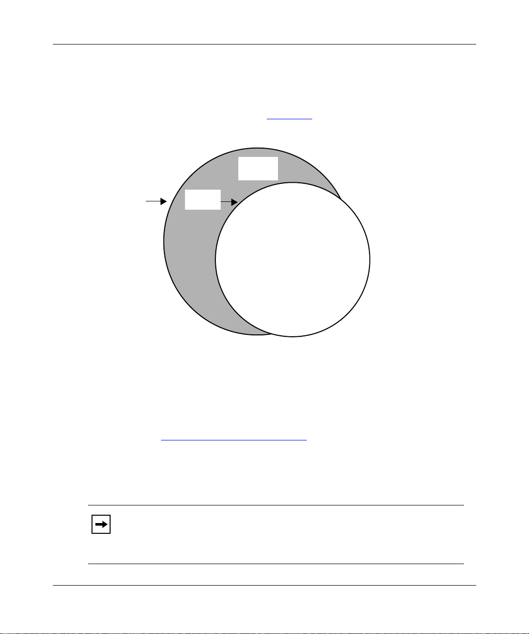
After logging on to a de vice , you access the BCC by entering t he
the Technician Interface prompt (Figure 1-1
Technician
Interface
bcc
command at
).
Login
Figure 1-1. Technician Interface and the BCC Interface
Access
the BCC
BCC
BCC0001B
From the BCC prompt, you can:
• Execute any system command not classified as “Technician Interface only”
(see Appendix B, “System Commands
”).
• Execute configurat ion commands to perfor m tasks such as c reating or de leting
IP interfaces on the router. Enter BCC configuration mode by entering the
config
command at the BCC prompt.
1-2
Note:
For a list of services you can configure using the BCC, see the Release
Notes. You can obtain a complete hierarchical listing of all objects
configurable on a device by entering the
help tree -all
command at any BCC
prompt.
308659-14.20 Rev 00
Page 21

Platform Requirements
The BCC runs on AN, ANH, ARN, ASN, System 5000, and BN platforms
including ARE, FRE
• 16 MB of dynamic RAM (DRAM)
• 2 MB of free memory space available when you start the BCC
If you try to start the BCC with insufficient DRAM or free memory on a slot, the
BCC returns an error message. In that case, use Site Manager instead of the BCC.
®
, and FRE-2 processor modules. Each slot must have:
Number of BCC Sessions
You can open one BCC session per slo t i n r ead- wri t e (configurati on) mode. Ot her
users can open additional BCC sessions in re ad- onl y (nonc onfiguration) mode on
the same slot, depending on available memory. Each BCC session is mutually
exclusive. If you make a change during a BCC session in read-write mode, this
change does not appear in other BCC sessions.
Overview of the BCC
Multilevel Access
Multilev el access adds a thir d login le v el, that of Oper ator , to the e xistin g Manager
and User login levels of the BCC. With multilevel access, multiple users (each
with a distinct user name and password) can access the router simultaneously.
Multilevel access allows you to:
• Add multiple user names, passwords, and access privileges to the router
• Manage the distrib u t io n of user names, p asswords, and a ccess privileges from
the BCC
• Vie w event logs sho wi ng each BCC command iss ued and t he use r resp onsibl e
for issuing the command
For more information on how to configure and use multilevel access features,
refer to Appendix A, “Multilevel Access
privilege level required to execute them, refer to Appendix B, “System
Commands.”
308659-14.20 Rev 00
.” For a list of system commands and the
1-3
Page 22

Using the Bay Command Console (BCC)
Terminology and Concepts
This sectio n describes key terms and concepts of the BCC interface.
Configuration Hierarchy
The BCC configuration hierarchy begins at a root-level object, called box for
AN/ANH, ARN, and BN platforms, and stack for ASN and System 5000
platforms. Under the root-level object are branch objects such as interfaces and
protocols that fan out from root level in a tree hierarchy.
You use the
help tree -all
show config -all
and
commands to display the
configuration hierarchy of a Nortel Networks router:
•The
help tree -all
command displays the hierarchy of every object you can
configure. (These are the configuration choices you can make. These are not
objects already configured.)
•The
show config -all
command displays the hierarchy of objects you have
actually configured.
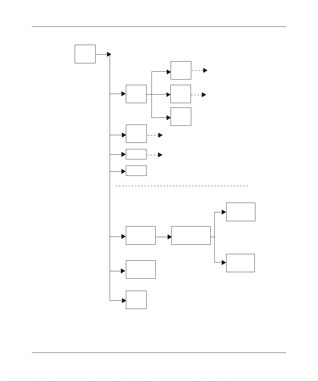
Figure 1-2
illustrates a sample BCC configuration for an AN, BN, or ARN router.
1-4
308659-14.20 Rev 00
Page 23
box
(root)
Overview of the BCC
ospf
(protocol)
ip
(protocol)
snmp
(protocol)
telnet
(protocol)
tftp
(protocol)
INTERFACE-SPECIFIC OBJECTS
(Services supported on a specific slot)
ethernet/2/1
(interface)
ethernet/2/2
(interface)
arp
(protocol)
rip
(protocol)
BOX-WIDE/GLOBAL OBJECTS
(Services supported on all slots)
ip/1.2.3.4/255.0.0.0
(protocol)
ospf/1.2.3.4
(protocol)
arp/1.2.3.4/1
(protocol)
Figure 1-2. Sample BCC Configuration
308659-14.20 Rev 00
serial/3/1
(interface)
BCC0012C
1-5
Page 24
Using the Bay Command Console (BCC)
You use BCC commands to create new objects and to modify or delete objects in
an existing configuration hierarchy. You begin at root level in BCC configuration
mode and navigate to objects in the device configuration tree.
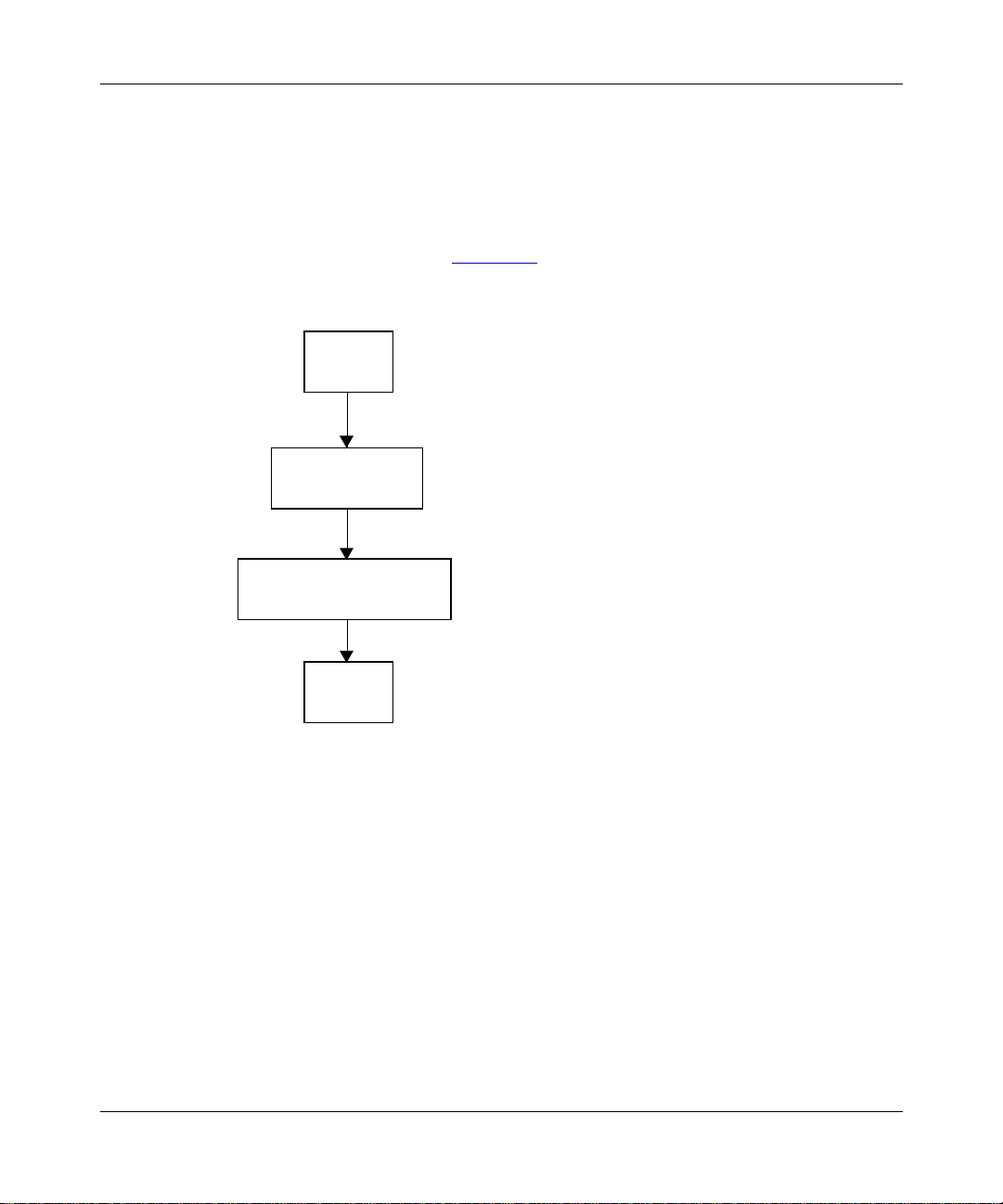
For exa mple, on a BL N rout er, you can use BCC commands to add a ne w phys ical
interface (such as Ethernet) on box, add IP to the Ethernet interface, and th en add
RIP to IP on that interface. Figure 1-3
to build this configuration.
box
box# ethernet/2/1
Ethernet
Slot 2
Connection 1
ethernet/2/1# ip address 1.2.3.4 mask 255.0.0.0
IP
Address 1.2.3.4
Mask 255.0.0.0
shows the seq uence of commands ne cessary
rip/1.2.3.4
Figure 1-3. Configuring IP and RIP on an Ethernet Interface
Configuration Context
Your working location within the BCC configuration tree is referred to as the
context. Just as a UNIX file system has a current working directory within which
you can add, modify, or delete files, the BCC configuration tree has a current
working context, within which you can add, modify, disable, reenable, or delete
objects.
1-6
ip/1.2.3.4/255.0.0.0# rip
rip/1.2.3.4#
BCC0017A
308659-14.20 Rev 00
Page 25
Overview of the BCC
The BCC displays the cont ext of an object in terms of its l ocation a long a pat h that
begins at the root level of the device configuration tree. Each semicolon in the
path marks a transition from one level to the next branch level in the device
configurat ion tree. Using a semic olon is als o equi v ale nt to pressi ng [Retu rn] at the
end of a command, effectively starting a new command line.
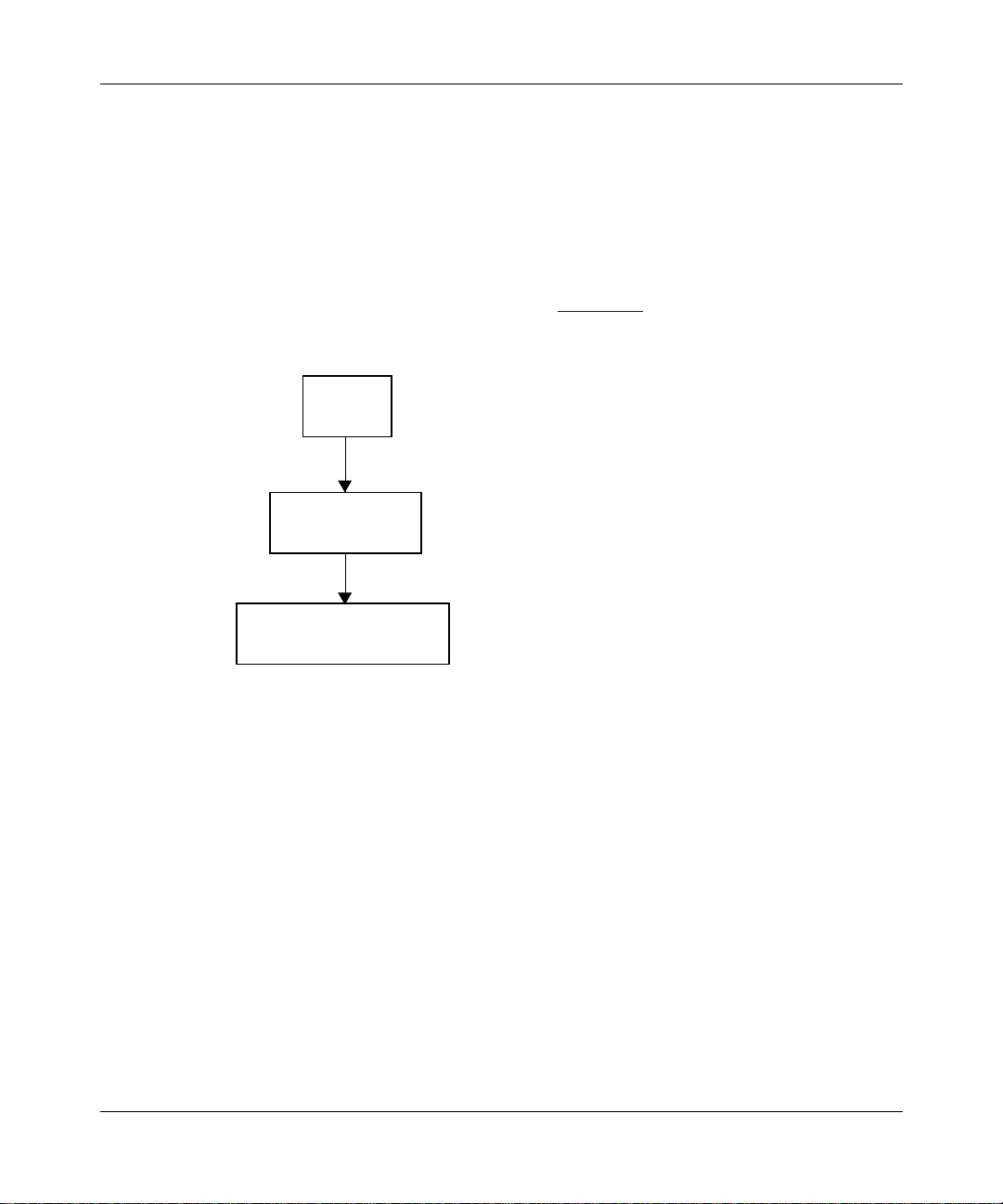
For example , if you co nf igur e an IP in te rf ace (add ress 1.2 .3.4, mask 255 .0.0.0) on
ethernet/2/1 of a BLN router, the BCC displays its location as
box; ethernet/2/1; ip/1.2.3.4/255.0.0.0 (Figure 1-4
box
box# ethernet/2/1
ethernet/2/1
ethernet/2/1# ip address 1.2.3.4 mask 255.0.0.0
).
Figure 1-4. Location or Context in Configuration Mode
308659-14.20 Rev 00
ip/1.2.3.4/255.0.0.0
ip/1.2.3.4/255.0.0.0#
BCC0017B
1-7
Page 26

Using the Bay Command Console (BCC)
Objects and Instances
In BCC terminology, configurable entities are r eferr ed to as ob jects of a pa rtic ular
class, each of which constitutes an instance:
•An object is a configurable physical or logical entity such as a physical
interface or a pr ot ocol on an interface. Every configurabl e object belongs to a
specific cla s s that defines its characteristics.
•A class is a template for a configurable object (such as Ethernet or the
protocol IP). When you add a new object to the configuration of a device, the
BCC creates a copy (instance) of the appropriate template.
•An instance is an object uniquely identifiable within the total device
configuration. Each instance is identified by its BCC instance identifier.
BCC Instance Identifier
A BCC instance identifier uniquely identifies a single instance of an object
configured on a de vi ce. Th e BCC in st ance I D consi sts typic ally of t he name of t he
object, combined with the values you specify for its required parameter s. For
example, the BCC insta nce ID for an Ether net i nterf ac e on a BN pl atfor m consis ts
ethernet/
of
Ethernet interface on an ASN platform consists of
ethernet/
<slot>/<connector>
<slot>/<module>/<connector>
, as in
ethernet/2/1
ethernet/1/2/2
, as in
; the BCC in stance ID for an
.
1-8
A configurable object may also have required parameters that do not become part
of its BCC instance ID. For example, the global OSPF object has a required
router-id parameter that does not become part of the instance ID.
Each object has it s own requirements for unique instance identificat ion within the
total device configuration.
Global (Box-Wide) Object s
Global (box-wide) objects provide services uniformly to all slots of a network
device. Examples include global IP, BGP, TCP, SNMP, FTP, TFTP, and Telnet.
Some protocols, such as IP, RIP, and OSPF, have global and interface-level
objects.
308659-14.20 Rev 00
Page 27

Overview of the BCC
Physical Device Objects
The following sections provide BCC terms for the physical device.
Box and Stack
The BCC uses the term box or st ack to identify the root level of the BCC
configuration tree for a Nortel Networks device. Every box or stack object has a
type parameter. The value assigned to the type parameter identifies the type of
Nortel Networks device chassis:
type
Value Router Model
an AN/ANH
arn ARN
asn ASN
freln BLN
frecn BCN
lite Passport 2430
fbr4slot Passport 5430
sys5000 System 5000
Board
The BCC uses the term board to identify any logic or circ uit board in a Nortel
Networks device. Each board typically occupies a slot in a network device. On
some Nortel Networks products, one board may contain another board such as an
RMON data collection module (DCM). All board objects have a type parameter
that identifies its hardware type. For example, “qenf” is the value of the type
parameter for a Quad Ethernet with Hardware Filters board.
Note:
for any board object, see the Release Notes.
308659-14.20 Rev 00
For board descriptions based on the literal value of the type parameter
1-9
Page 28

Using the Bay Command Console (BCC)
Module
The BCC uses the term module to identify network media-specific I/O modules
(such as, Ethernet and token ring). Each module has one or more connectors for
attachment to a physical network transmission medium.
Slot
The BCC uses the term slot to identify the location, as well as a physical and
electrical means , for attac hing boa rds to l ogic an d power connection s a vailable on
the device chassi s. Note the following:
• Multislot devices such as the BLN or BCN router accommodate a system
module (SRM-L) in one slot, and one link module in each remaining slot.
• Single-slot devices such as the AN, ANH, ASN, and ARN routers
accommodate one base module (slot 1), which may be augmented by one or
two adapter modules and one expansion module.
Connector
The BCC uses the term connector to identify the physical and electrical means to
interconnect a network device (slot or module) directly or indirectly to a physical
network transmission medium.
1-10
Line
The BCC uses the term line to identify the physical (and in some cases, logical)
circuit identified typically by means of a slot, connector, interface type (ethernet,
sync, fddi, and so on), and, where applicable, a channel number (such as with
T1/E1 interface types).
Port
The BCC uses the term port to identify an interface object defined by its type (for
example, an Ethernet port) and location (slot and connector) within a network
device. On a network device, a port is also a logical point of termination for data
sent or received by a specific protocol or application.
308659-14.20 Rev 00
Page 29

Parameters
Overview of the BCC
Interface
The BCC uses the term interface to identify circuitry and digital logic associated
with the interconnection between a physical network medium (such as Ethernet)
and a higher-layer protocol entity (such as IP).
Note:
A logical interface is an ad dressable entity for originating a nd
terminating connections across an IP network.
A parameter is an attribute (or property) of a configurable object. Parameters can
be classified as one of the following:
•Required
• Derived
• Optional
Required
For any BCC object, required parameters are a minimum set of parameters for
which the BCC requires you to supply values. For example, the required
parameters of a physical port are
Derived
Derived parameters are parameters for which the BCC supplies a value. For
example, a derived parameter of the global OSPF object is
the BCC derives a value for
configured on the device.
Optional
Optional parameters are par ameters for wh ich you ca n specif y custo mize d v a lues,
replacing any default values set by the system. For example, an optional parameter
of an Ethernet interface is
value of 5 (5 retries), but you can change this to another numeric value.
308659-14.20 Rev 00
slot
router-id
bofl-retries
connector
and
.
router-id
. In this case,
from the add ress of the first IP interface
. This parameter normally has a default
1-11
Page 30

Page 31

Chapter 2
Getting Started with the BCC
This chapter provides information about the following topics:
Topic Page
Entering and Exiting the BCC Interface 2-2
Displaying Your Location in Configuration Mode 2-4
Navigating in Configuration Mode 2-4
Displaying Configuration Data 2-9
Displaying Help on System Commands 2-28
Displaying Help on show Commands 2-29
308659-14.20 Rev 00
2-1
Page 32

Using the Bay Command Console (BCC)
Entering and Exiting the BCC Interface
To access the BCC interface on a Nortel Networks router:
1.
Open a Technician Interface session with the target router.
For detailed information about opening a Technician Interface session, see
Using Technician Interface Software.
2.
Enter the
Manager, Operator,
or
User
command at the login prompt that
appears on your Telnet or console display.
The Manager login allows you to enter any system command and allows
read-write access to the device configuration. The Operator login allows you to
enter only operator-level system commands and allows limited access to the
device configuration. The User login allows you to enter only user-level system
command and allows read-only access to the device configuration. For a list of
system commands and the privilege level required to execute them, refer to
Appendix B, “System Commands
3.
* To enter configuration mode, type config
* To list all system commands, type?
* To exit the BCC, type exit
bcc
Enter
Router1>
Welcome to Bay Command Console!
bcc>
at the Technician Interface prompt.
bcc
.”
Note:
2-2
Attempting to start the BCC at the Technician Interface prompt before the router
has completed booting up may cause a loading error to occur. Select one of the
following two options to prevent or bypass this error:
• To pre v ent the e rror cond itio n, wait u ntil the route r has comple ted boot ing
up before starting the BCC.
bcc
• To bypass the error condition, re-enter the
command following the
fault and pres s [Enter ]. The BCC wi ll the n start while the router is boot ing
up.
308659-14.20 Rev 00
Page 33

Getting Started with the BCC
Enter
bcc>
box#
config
at the BCC prompt.
config
4.
You enter configur ation mode a t th e root (box ) level of the BCC configur ation
tree. The prompt ends with a pound symbol (#) if you have read-write
privileges (Manager only), or with a greater than symbol (>) if you have
read-only privileges (Manager or User).
If you enter BCC configuration mode as Manager and want to change your
privilege level for the current session from read-write to read-only, enter
config -read-only. To change Manage r privileges back to read -write, enter
config -read-write. You cannot change your pri vilege level from read-only to
read-write if you logged in as User.
Caution:
When you enter BCC configuration commands with read-write
privileges, you immediately modify the device configuration.
5.
When you finish using BCC confi gur ati on mode , ent er the
exit
command
at any prompt.
box#
bcc>
6.
When you finish using the BCC, enter the
exit
exit
command at the BCC
prompt.
bcc> exit
Router1>
For more detailed information about Technician Interface access, login, or logout
procedures, see Using Technician Interface Software.
308659-14.20 Rev 00
Exiting the BCC returns you to the Technician Interface prompt.
2-3
Page 34

Using the Bay Command Console (BCC)
Displaying Your Location in Configuration Mode
In configuration mode, the BCC displays a context-sensitive prompt. The prompt
identifies the configured object at your current working location within the
configuration hierarchy. For example, after logging in to a BLN router as
Manager, then configuring or navigating to the Ethernet interface on slot 2
connector 1, the BCC displays the following prompt:
ethernet/2/1#
To display the complete path from root level to your current level in the device
configuration tree, enter the
Example:
rip/192.168.125.34# pwc
box; ethernet/2/1; ip/192.168.125.34/255.255.255.224; rip/
192.168.125.34;
pwc
The
command displays the BCC instance ide ntif ier of ea ch conf igured ob ject
in the path.
pwc
(print working context) command.
Navigating in Configuration Mode
You can navigate from one obj ect to a nother in BCC conf ig urati on mode b y using :
back
•The
• Configuration commands
Navigating with the back Command
In BCC configura tion mod e, use th e
levels back toward root level. This is the syntax for the
back
[
<n>
n
is the number of levels.
Entering the
root level.
2-4
command
]
back
command with no argument mo ve s you back one le v el clo ser to
back
command to move a spe cif i c number of
back
command:
308659-14.20 Rev 00
Page 35

Getting Started with the BCC
Example:
rip/192.168.125.34# back
ip/192.168.125.34/255.255.255.224# back
ethernet/2/1#
Entering the back command with an integer moves you from your current
working location, back toward root, the number of levels you specify.
Example:
rip/192.168.125.34# back 2
ethernet/2/1#
In this example, the back 2 command moves you from the current working
location (rip/192.168.125.34), back two levels to ethernet/2/1 (with
ip/192.168.125.34/255.255.255.224 as the intervening level).
Note:
If you enter an integer value that exceeds the actual number of levels
back to root (box or stack) level, the BCC returns to root level.
Navigating with Configuration Commands
Using BCC configuration commands, you can:
• Move back to a previous level
• Move back to root level
• Move for ward to the next level
• Move from your current level to any other level in the device configuration
tree
Moving Back One or More Le vels
To move from your current working level back one or more levels closer to root
leve l of the de vice conf igurat ion tree , ente r the ful l BCC inst ance ID of the de sired
object.
Example (go back one level):
rip/192.168.125.34# ip/192.168.125.34/255.255.255.224
ip/192.168.125.34/255.255.255.224#
308659-14.20 Rev 00
2-5
Page 36

Using the Bay Command Console (BCC)
Example (go back two levels):
rip/192.168.155.151# ethernet/2/1
ethernet/2/1#
In the second example, the BCC searches back toward root until it finds a context
or level where the object you specified (in this case, ethernet/2/1) exists in the
router configuration tree. The BCC enters the context of this object, and the
prompt displays your new location.
Moving Back to Root Level
You can move back to root level in configuration mode by entering the name of
the object at that level.
For an AN, ANH, ARN, or BN router, enter:
ip/1.2.3.4# box
box#
For an ASN or System 5000 router, enter:
ip/1.2.3.4# stack
stack#
2-6
Moving Forward One or More Levels
T o move f rom your curr ent workin g le vel to the next config ured le vel (F igure 2-1
),
enter the BCC instance ID of the desired object.
Example:
box# ethernet/2/1
ethernet/2/1# ip/1.2.3.4/255.0.0.0
ip/1.2.3.4/255.0.0.0# rip
rip/1.2.3.4#
Notice that a slash (/) joins the name and any required parameter values to make a
BCC instance ID for any configured object.
308659-14.20 Rev 00
Page 37

Getting Started with the BCC
box# eth 2/1
box
(Starting
context)
ethernet/2/1
ethernet/2/1# ip/1.2.3.4/255.0.0.0
ip/1.2.3.4/255.0.0.0# rip
Figure 2-1. Moving Away from Root Level
Moving to Any Context in the Device Configuration
T o nav igate to an y conf igured object, y ou can spec ify a fu ll, or absol ute, path from
root (box or stack) level at any prompt. When you enter a path, specify the BCC
instance identifier of each object.
ip/1.2.3.4/255.0.0.0
(Ending
context)
rip/1.2.3.4#
rip/1.2.3.4
BCC0014B
Example:
To move from ip/192.168.33.66/255.255.255.0 (on ethernet/2/1) to rip/1.2.3.4 on
ethernet/2/2 (Figure 2-2
ip/192.168.33.66/255.255.255.0# box;ethernet/2/2;ip/1.2.3.4/255.0.0.0;rip
rip/1.2.3.4#
308659-14.20 Rev 00
), enter the fo llowing command:
2-7
Page 38

Using the Bay Command Console (BCC)
(Starting context)
ethernet/2/1
box
ethernet/2/2
ip/192.168.33.66/255.255.255.0
ip/1.2.3.4/255.0.0.0
(Ending context)
rip
BCC0009B
Figure 2-2. Navigating to an Object in the Configuration
The BCC can automatically search backward (recursively) toward root level until
it finds a l evel where the object you specify first in the co mma nd line exists in the
device configuration tree.
Example:
To move from ip/192.168.33.66/255.255.255.0 on ethernet/2/1 to rip/1.2.3.4 on
ethernet/2/2, enter the following command:
2-8
ip/192.168.33.66/255.255.255.0# ethernet/2/2;ip/1.2.3.4/255.0.0.0;rip
rip/1.2.3.4#
In this examp le, th e BCC sear ches ba ckw ard to f i nd ethe rnet/ 2/2 ( specified fir st in
the command line), and then moves sequentially to the other locations
(ip/1.2.3.4/255.0.0.0 and rip) specified next in the command line.
308659-14.20 Rev 00
Page 39

Getting Started with the BCC
(Starting context)
ethernet/2/1
box
ethernet/2/2
Figure 2-3. Navigating with the BCC Recursive Search Feature
Displaying Configuration Data
There are several BCC help commands that let you:
• Display information on objects in the active (actual) device configuration
• Display information on objec ts that you can add to the current configuration;
these are
? and help tree [-all]
ip/192.168.33.66/255.255.255.0
ip/1.2.3.4/255.0.0.0
(Ending context)
rip
BCC0009C
Displaying Current/Active Configuration Data
With the show config and lso commands, you can display:
• The current device configuration
• The operating parameters of each configured object
• Th e value s set for the pa rameters of eac h configured object
308659-14.20 Rev 00
2-9
Page 40

Using the Bay Command Console (BCC)
The optional arguments you add to these commands depend on what you want to
see, as follows:
Command Task
show config
: Combine the following
Note
command options to customize
show config
output.
<BCC_instance_ID>
-recursive
-verbose
-all
Show the configuration of the current object only . (Entered without
any command
configured on the current object.)
Show the configuration of this object (specified by the BCC
instance identifier).
Show any dependent objects configured on this (current or
specified) object.
Examples
• show config -recursive
• show config -compact -recursive
• show config ip/1.2.3.4/255.0.0.0 -recursive
Show the conf iguration including the current (default or
nondefault) value of every parameter of the objects shown.
Examples
• show config -verbose
• show config -recursive -verbose
• show config ip/1.2.3.4/255.0.0.0 -recursive -verbose
Show the total device configuration.
Examples
• show config -all
• show config -all -verbose
-<option>
:
:
:
,
show config
does not display objects
2-10
-compact
-
file
<filename>
Show the conf iguration without navigation (
Example:
Note
contents of a file saved using the
Save the output of this command to a file.
Examples
• show config -file boston.config
• show config -recursive -verbose -file boston.config
show config -compact
: In configuration mode, do not import (using
-compact
:
) commands.
back
source
option.
308659-14.20 Rev 00
) the
Page 41

Getting Started with the BCC
Note:
The show config command does not display the values of parameters
currently set to their default values unless you use the
-verbose argument.
Regardless of the command options you enter, output of the show config
command typically includes:
• Objects added by a user into the active device configuration
• Objects added automatically by the BCC to support a user-configured object
The arguments you add t o the
as follows:
Command T ask
lso
lso -list
lso -recursive
|
lso [-r
<pattern>
List only next-level objects configured on the current object.
(Display output in tabular format.)
Example:
List only next-level objects configured on the current object.
(Display output in nontabular format.)
Example:
List, by BCC instanc e identi fier , objects configure d at e v ery le v el on
the current object. (Display the path from root level to each
configured object.)
Example:
: You cannot combine the
Note
command.
Show objects configured at the next (branch) level.
]
If issued with the
branch levels.
If issued at the
and the paths to those objects.
If issued with a “glob-style” string pattern (using * and ? wildcards,
and no regular expressions), list only configured objects in the
current context that match the specified pattern. For example:
lso command also depend on what you wa nt to se e,
lso
lso -l
lso -r
and
-l
flag, show objects configured a t a ll descending
-r
prompt, show all objects in the configuration
box#
arguments of the
-r
lso
308659-14.20 Rev 00
lso *o* lso *a* lso “ip/1.2.?.?/*”
2-11
Page 42

Using the Bay Command Console (BCC)
Displaying Configured Objects
You can display:
• The current object (the object shown in the BCC configuration prompt)
• An object you specify by BCC instance ID
• Objects configured at the next (subcontext) level
• All branches configured on the current object
• The total device configuration tree (active configuration only)
• The IDs of all configured objects
• The active configuration in compact format
Displaying the Current Object
To display the configuration of the current object, minus any dependent objects
configured on the same branch, use th e
Example:
ethernet/2/1#
ethernet slot 2 connector 1
circuit-name E21-alpha
show config
show config
command.
2-12
Displaying a Specified Object
To display the configuration of any object you specify by BCC instance ID from
any configuration context, enter the following command:
show config
BCC_instance_ID
<BCC_Instance_ID>
is the identifier assigned by the BCC to uniquely identify a
specific object in the active device configuration.
Example:
Show the configuration of an object with the ID
ip/192.168.125.34/255.255.255.224.
ethernet/2/1#
ip address 192.168.125.34 mask 255.255.255.224
broadcast 192.168.125.32
show config ip/192.168.125.34/255.255.255.224
308659-14.20 Rev 00
Page 43

Getting Started with the BCC
To display the configuration of all other objects configured on the same branch,
add the
-recursive (or -r) option to the show config
<BCC_instance_ID>
command.
Example:
box# show config ip/192.168.125.34/255.255.255.224 -r
ip address 192.168.125.34 mask 255.255.255.224
broadcast 192.168.125.32
arp
back
rip
back
back
Displaying Unsatisfied Dependent Object s in the Current Context
To display any unsatisfied dependent objects (requiring additional configuration)
in the current context by default, enter:
check [-recursive | -all]
• Use the “-recursive” option to check for dependencies related to the current
context and all of its subcontexts.
• Use the “
The
Displaying Objects at the Next Subcontext Level
To display by BCC instance identifier any objects configured at the next
subcontext level accessible from your current location in configuration mode, use
the
Example:
Display in tabular format a list of objects configured on the current object. Show
the BCC instance identifier of each configured object.
box#
board/1 board/4 dns ip telnet
board/2 board/5 ethernet/2/1 snmp tftp
board/3 console/1 ftp syslog
308659-14.20 Rev 00
-all” option to che ck fo r dep endenci es ass ociat ed with al l configured
contexts.
check command operates only in config mode.
lso or lso -list (lso -l) com mands.
lso
2-13
Page 44

Using the Bay Command Console (BCC)
Example:
Display in nontabular format a list of objects configured on the current object.
Show the BCC instance identifier of each configured object.
box# lso -l
board/1 board/2 board/3 board/4 board/5 ftp snmp tftp console/1
telnet ethernet/2/1 ip dns syslog
Displaying Objects at All Subcontext Levels
To display in hierarchical format the act i ve configur ation of t he cur rent ob jec t and
any other dependent objects configured on the same branch, use the
show config -recursive
Example:
box# eth 2/1
ethernet/2/1# show config -r
ethernet slot 2 connector 1
circuit-name E21-alpha
ip address 192.168.125.34 mask 255.255.255.224
broadcast 192.168.125.32
arp
back
rip
back
back
back
command.
2-14
Output of the
show config -r
command includes any
back
commands necessary
for navigation back from the current context to the prior context.
Note:
If you enter
BCC displays the same output as
show config -r
at root level in configuration mode, the
show config -all
.
308659-14.20 Rev 00
Page 45

Displaying the Total Device Configuration
To display the hierarchical listing of every object actively configured on this
device, use the
show config -all command.
Example:
box#
show config -all
box
type frecn
build-version {BayRS ## BCC ##}
board slot 5
type sync
back
board slot 7
type srml
back
board slot 9
type dtok
. . .
. . .
. . .
console portnum 1
prompt {"%slot%:"}
auto-manager-script automgr.bat
auto-user-script autouser.bat
back
ethernet slot 13 connector 1
circuit-name E131
ip address 192.168.133.114 mask 255.255.255.224
arp
back
rip
back
back
back
. . .
. . .
. . .
Getting Started with the BCC
Note:
show config -recursive at root level in configuration mode.
308659-14.20 Rev 00
The BCC displays the same output as show config -all when you enter
2-15
Page 46

Using the Bay Command Console (BCC)
Displaying the Path to Every Configured Object
To display by BCC instance identifier the path to every object configured at the
next subcont ext levels, enter the
current context.
lso -recursive (lso -r) command from your
Note that
lso -r intially lists all objects con figur ed at the next sub conte xt le vel, and
then displays the detailed path to each of those objects in standard BCC
configuration syntax.
Example (from root level, BLN router):
box#
lso -r
board/1 board/4 dns ip telnet
board/2 board/5 ethernet/2/1 snmp tftp
board/3 console/1 ftp syslog
box; board/1;
box; board/2;
. . .
. . .
. . .
box; snmp;
community/public
box; snmp; community/public;
manager/public/0.0.0.0 manager/public/192.32.241.36
box; snmp; community/public; manager/public/0.0.0.0;
box; snmp; community/public; manager/public/192.32.241.36;
. . .
. . .
. . .
2-16
Example (from an IP interface on ethernet/2/1):
ip/192.168.125.34/255.255.255.224#
arp/192.168.125.34/1 rip/192.168.125.34
box; ethernet/2/1; ip/192.168.125.34/255.255.255.224; arp/
192.168.125.34/1;
box; ethernet/2/1; ip/192.168.125.34/255.255.255.224; rip/
192.168.125.34;
lso -r
308659-14.20 Rev 00
Page 47

Getting Started with the BCC
Displaying Configur ed Objects in Compact Format
To display in compact format the active configuration of the current object or any
object you specify by BCC instance ID, use the
command. Command output excludes any
show config -compact
back commands otherwise shown for
navigation from the current context to the prior context.
Example:
Display the conf igura tion o f your curren t cont e xt, eth ern et/2/1, i n compact format .
ethernet/2/1# show config -compact
ethernet slot 2 connector 1
circuit-name E21-alpha
Or from any context, supply the BCC instance ID.
box# show config -compact ethernet/2/1
ethernet slot 2 connector 1
circuit-name E21-alpha
To display the entire device configuration in compact format, add the -all option.
box# show config -all -compact
box
type freln
build-version {BayRS 13.10 BCC 4.10}
contact { }
system-name { lab }
location Billerica
help-file-name bcc.help
board slot 1
type srml
board slot 2
type qenf
board slot 3
type wffddi2m
board slot 5
type dtok
ftp
default-volume 2
snmp
lock-address 255.255.255.255
community label public
. . .
. . .
. . .
308659-14.20 Rev 00
2-17
Page 48

Using the Bay Command Console (BCC)
Displaying Configured Parameter Values
You can display values configured for any specific parameter, or all parameters,
of:
• The current object
• An object configured at the next subcontext level
• An object you specify by BCC instance identifier
• Objects configured at all subcontext levels beyond your current location or
ID-specified location in the active device configuration.
Displaying the Value of One Parameter
To display the value assigned to a specific parameter of the current object or an
object configur ed at the next (su bcontext) level, just enter the paramete r name:
ethernet/2/1#
bofl-timeout 5
bofl-timeout
The BCC returns the name and value assigned to the parameter you specified.
You can also use the
command to obtain essential ly the same in formation i n a
info
more terse format.
ethernet/2/1#
5
info bofl-timeout
T o displa y the most detaile d inform ation on v alu es for t he same para mete r , us e the
command.
?
ethernet/2/1#
Current Value: 5
Legal Values: <unsigned integer>
Default Value: 5
bofl-timeout ?
To display the value assigned to any parameter of an object configured at the next
subcontext level, first obtain a list objects configured at the next subcontext level.
ethernet/2/1#
ip/192.168.125.34/255.255.255.224
lso
2-18
308659-14.20 Rev 00
Page 49

Getting Started with the BCC
Next, copy and p aste into the c urren t command line the BCC ins tance id entifier of
the desired object, followed by the name of the parameter you want to check for
current value.
ethernet/2/1# ip/192.168.125.34/255.255.255.2 24 address-res o lution
address-resolution arp
For the most detailed information on the same parameter, use the ? command.
ethernet/2/1# ip/192.168.125.34/255.255.255.224 address-resolution ?
Current Value: arp
Legal Values:
arp,ddn,pdn,in-arp,arp-in-arp,none,bfe-ddn,probe,arp-probe,atm-arp
Default Value: arp
Displaying All Parameter Values of an Object
To display parameter settings for the current object, use the info or
show config -verbose commands.
Example (using the
ethernet/2/1# info
bofl enable
bofl-timeout 5
bofl-retries 5
bofl-tmo-divisor 1
circuit-name E21-alpha
connector 1
hardware-filter disable
receive-queue-length 0
slot 2
state enabled
transmit-queue-length 0
Example (using the
ethernet/2/1# show config -v
ethernet slot 2 connector 1
bofl enable
bofl-timeout 5
bofl-retries 5
bofl-tmo-divisor 1
circuit-name E21-alpha
hardware-filter disable
receive-queue-length 0
transmit-queue-length 0
state enabled
info
command):
show config -verbose
command):
308659-14.20 Rev 00
2-19
Page 50

Using the Bay Command Console (BCC)
From any configuration context, use the following command to display all
parameter values associated with an object anywhere in the active device
configuration.
show config
<BCC_instance_ID>
-verbose
Example:
box# show config ip/192.168.125.34/255.255.255.224 -v
ip address 192.168.125.34 mask 255.255.255.224
state enabled
assocaddr 0.0.0.0
cost 1
broadcast 192.168.125.32
configured-mac-address 0x
mtu-discovery disabled
mask-reply disabled
all-subnet-broadcast disabled
address-resolution arp
proxy disabled
host-cache-aging cache-off
udp-checksum enabled
end-station-support disabled
redirects enabled
cache-size 128
Displaying Parameter Values for All Objects on a Branch
To display the parameter values assigned to all objects accessible from your
current context, or from a context you specify by BCC instance identifier, use the
following command.
2-20
show config [
or:
show config [
<BCC_instance_ID>
<BCC_instance_ID>
] -recursive -verbose
] -r -v
308659-14.20 Rev 00
Page 51

Getting Started with the BCC
Example:
Display parameters of an obj ect conf igured at th e next subconte xt le v el, rel ati v e to
your current location in the device configuration tree.
box# eth 2/1 (first navigate to the object)
ethernet/2/1# show config -r -v
ethernet slot 2 connector 1
circuit-name E21-alpha
state enabled
bofl enable
bofl-timeout 5
hardware-filter disable
transmit-queue-length 0
receive-queue-length 0
bofl-retries 5
bofl-tmo-divisor 1
ip address 192.168.125.34 mask 255.255.255.224
state enabled
assocaddr 0.0.0.0
cost 1
broadcast 192.168.125.32
. . .
. . .
. . .
back
rip
state enabled
supply enabled
listen enabled
. . .
. . .
. . .
back
back
back
308659-14.20 Rev 00
2-21
Page 52

Using the Bay Command Console (BCC)
Example:
Display parameters associated with all objects configured on
ip/192.168.125.34/255.255.255.224.
box# show config ip/192.168.125.34/255.255.255.224 -r -v
ip address 192.168.125.34 mask 255.255.255.224
state enabled
assocaddr 0.0.0.0
cost 1
. . .
. . .
. . .
arp
state enabled
back
rip
state enabled
supply enabled
. . .
. . .
. . .
back
back
Displaying Configuration Choices
From your current location in BCC configuration mode, you can display the
following information on objects, parameters, and parameter values available for
you to configure on a Nortel Networks device.
Command Task
?
<parameter_name>
or:
<adjacent_object_name> <parameter_name>
2-22
?
Display o bj ects (subcontexts) available for y ou to
configure on the current object.
Display the names of parameters of the current
object.
Display the current, legal , and default values for
any parameter of the current object, or for any
parameter of an object at the next (adjacent)
?
subcontext level in the device configuration tree.
(continued)
308659-14.20 Rev 00
Page 53

Getting Started with the BCC
Command Task
help tree
help tree -all
Displaying the Total Device Configuration Tree (All Av ail abl e Choices)
To display, from any BCC prompt, every object you can choose to add to the
current device configuration, use the
Example (BCN router):
box#
The entire configuration tree is:
board
virtual
ip
ospf
neighbor
ftp
http
ntp
peer
snmp
community
manager
trap-entity
trap-event
tftp
console
telnet
client
server
atm
atm-interface
signaling
timers
signaling-vc
ilmi
ilmi-vc
sscop
. . .
help tree -all
Display t he ob jec ts availa ble at every level on the
current branch, starting from your current
location.
Display the entire tree of objects available for you
to configure on this device.
help tree -all
command.
308659-14.20 Rev 00
2-23
Page 54

Using the Bay Command Console (BCC)
Displaying Choices Available from the Current Context
To list the names of all objects and parameters you can access from the current
context in configuration mode, enter the
Example:
command.
?
ip/192.168.125.34/255.255.255.224#
Sub-Contexts:
arp igmp ospf rdisc rip
Parameters in Current Context:
address cost on
address-resolution end-station-support proxy
all-subnet-broadcast has redirects
assocaddr host-cache-aging state
broadcast mask udp-checksum
cache-size mask-reply
configured-mac-address mtu-discovery
The subcontexts section lists the objects that you can add from your current
location in the device configuration tree (Figure 2-4
RIP OSPF
IP
ARP
(Created
automatically
with IP)
?
).
IGMP RDISC
BCC0019A
Figure 2-4. Objects You Can Configure at the Next (Subcontext) Level
Displaying Choices Available at All Subcontext Levels
To list the objects you can access and add to the device configuration from your
current location in BCC configuration mode, enter the
help tree
is an easy way to see the navigational path you must fol l ow to conf igure an object
several levels away from your current location.
2-24
command. This
308659-14.20 Rev 00
Page 55

Getting Started with the BCC
Example:
ethernet/2/1# help tree
The configuration tree below this context is:
ip
arp
rip
ospf
neighbor
rdisc
igmp
relay
ipx
rip
sap
static-route
adjacent-host
static-service
route-filter
server-network-filter
server-name-filter
auto-neg
Entering the help tree command at root level (box or stack) is the same as
entering the
help tree -all command from any configuration context.
Displaying Parameter Definitions
To display configuration syntax (usage) help and parameter definitions for any
object within the device configuration tree, enter the following command:
help <
object_name>
object_name
configurable item) that you can configure using the BCC interface.
308659-14.20 Rev 00
is the BCC designation for any object (interface, protocol, or other
2-25
Page 56

Using the Bay Command Console (BCC)
Example:
ethernet/2/1# help ethernet
Usage: "ethernet slot <value> connector <value>"
Or: "ethernet <slot>/<connector>"
ethernet Parameters:
_________________________________________________________________
state
Indicates the administrative state of this object (enabled
or disabled).
bofl
Allows breath-of-life polls to be disabled.
bofl-retries
Specifies the BOFL Retry Count.
. . .
If the
object_name
is unique among all object names in the BCC configuration
tree, the BCC displays the parameter definitions you requested. If the
object_name
is not unique among all object names (the same name exists in
multiple locations in the BCC configuration tree ), t he BCC ret ur ns a li st of t he al l
help commands that lead to an object that contains the
specified.
object_name
you
2-26
For exampl e, you may want to se e the d efinitions for a ll pa rameter s of “ ip,” b u t IP
has a global component and can exist in any interface context, as well. The name
“ip” also exists in “ipx,” which causes the BCC to list the help commands for
every ip and ipx object.
308659-14.20 Rev 00
Page 57

Getting Started with the BCC
This happens when you enter help ip:
ethernet/13/1# help ip
"help ip" is ambiguous. Copy and re-enter one of the following
commands:
help atm classical-ip-service ip
help atm lec-service ip
help atm lec-service ipx
help atm pvc-service ip
help atm pvc-service ipx
help box ip
help box ipx
help demand-pool demand-circuit frame-relay default-service ip
help demand-pool demand-circuit frame-relay default-service ipx
. . .
. . .
. . .
help serial ppp ipx
help serial ppp ipxwan
help serial standard ip
help serial standard ipx
help token-ring ip
help token-ring ipx
help virtual ip
Notice that the response starts with “Copy and re-enter one of the following
commands.” For example, if you copy and re-enter the explicit command
help ethernet ip, the BCC immediately displays usage help and parameter
definitions for that particular “ip.”
ethernet/13/1#
Usage: "ip address <value> mask <value>"
Or: "ip <address>/<mask>"
ip Parameters:
_________________________________________________________________
state
Indicates the administrative state of this object (enabled
or disabled).
address
-REQUIRED- Specifies the IP address of this interface.
address-resolution
Specifies the address resolution type.
. . .
308659-14.20 Rev 00
help ethernet ip
2-27
Page 58

Using the Bay Command Console (BCC)
If you want to display the definition for a specific parameter of the current object
only, enter
help
<parameter_name>.
(By default, the BCC displays the enti re list
of parameter definitions for the current object.)
Saving Displayed Configuration Data
For more information on using the show config -file command to save
configuration data to a file, see “Saving Configuration Commands to a File on a
Device” on page 3-14.
Displaying Help on System Commands
Table 2-1 lists the commands that explain how to use BCC system commands.
Table 2-1. Help for BCC System Commands
Command Help Feature
help
<command>
help
help commands
help commands -more
help editing
help learning-bcc
help syntax
Get an overview of Help-oriented command features.
Get full details on a specific command.
Display the syntax of all BCC commands in alphabetical order.
Display the syntax and brief command descriptions for all BCC
commands in alphabetical order.
Get Help on how to edit BCC commands and command lines.
Get Help on performing common BCC operations. This command
provides a short tutorial on how to use the BCC interface.
Get Help on how to interpret symbols used to describe BCC
command syntax.
2-28
308659-14.20 Rev 00
Page 59

Displaying Help on show Commands
show
BCC
show
<filter>[<filter_argument>
-[
commands use the following syntax:
<object_name> <keyword>
]]
...[
<keyword>
Getting Started with the BCC
] -[
<filter>[<filter_argument>
]]...
object_name
is the name of a c onfigured objec t, suc h as ip,
only exception to this rule is
show config
ethernet
, described in “Displaying
, or
dns
. The
Configuration Data” on page 2-9.
keyword
want to see, such as
keyword levels, such as
-
filter
is a subcommand that further specifies what aspect of
show ip routes
show frame-relay stats lapf errors
is a command option that limits
. Many
show
object_name
show
commands have multiple
.
command output to a specific subset
you
or filtered view of the total information available. You must enter the dash
character (-) and the
show frame-relay stats lapf errors -interface
single command, such as
filter_argument
filter_argument
such as
show frame-relay stats lapf errors -interface
refers to the
further restricts the filtered output from a
To display any available
filter_argument
, use the ? command, as follows:
• To display a list of every
show ?
enter
explicitly, with no space between the t wo, for example,
filter
. You can often combine filters in a
show atm interfaces -disabled -slot 9.
preceding it in the command line. The
filter
show
command,
<interface_address>
show
command
object_name
object_name, keyword, filter
ava ilable for th e BCC
show
, or
command,
.
Example:
bcc>
show ?
access dsucsu hifn mct1e1 sonet
atm dsx3 hssi modem syslog
bgp dvmrp http mtm system
bri ethernet hwcomp ntp tcp
classical-ip fddi igmp ospf telnet
config frame-relay ip ppp tftp
console ft1e1 ipx process token-ring
dial ftp isdn-switch serial wcp
dns hardware lane snmp
• To display every
308659-14.20 Rev 00
show
<object_name>
keyword
?
available for a specific
object_name
, enter
2-29
Page 60

Using the Bay Command Console (BCC)
Example:
bcc> show frame-relay ?
congestion services stats svcs
multiline shaping summary vcs
For show commands that have additional keyword levels:
bcc> show ip stats ?
cache fragments security
datagrams interface summary
• To display every command, insert the
filter
and
filter_argument
? where filters and their arguments would appear after
available for a specific show
any keywords in the command line.
Example:
bcc>
show frame-relay congestion ?
show frame-relay congestion [-state <arg>][-interface <arg>]
[-service <arg>] [-dlci <arg>]
Usage Notes:
• Use the show command to display routing, configuration, interface, and
statistical data from the Management In formation Base (MIB). The type and
amount of data displayed depends on the specific protocol, network service,
and/or filtered view you want to see.
• Use lowercase for all show commands.
•
pattern
Use
means that you can u se wildca rd sea rching wi th the * and ? characters.
* to find a string of any characters of any length. Use ? to designate any
character in a specific position of the search string. For example, to locate all
networks whose addresses begin with 29, enter the following command:
string 29*
This pattern will locate the addresses 2901456 and 2967. Or if you have a set
of names that begin and end with the same characters but have different
characters in t he midd le, such as xxx1.yy , xxx2.yy, and so on, you can enter the
search pattern
xxx?.yy
to locate them.
2-30
308659-14.20 Rev 00
Page 61

Chapter 3
Entering Commands and Using Command Files
This chapter provides information about the following topics:
Topic Page
Entering Commands 3-2
System Commands 3-6
Configuration Command Syntax 3-6
Creating and Using BCC Files 3-13
308659-14.20 Rev 00
3-1
Page 62

Using the Bay Command Console (BCC)
Entering Commands
This section contains information about:
• Using Command Abbreviations
• Recalling Commands
• Using Command Completion
• Editing Command Lines
• Entering Multiple Commands on a Line
• Continuing a Command Line
Using Command Abbreviations
When you enter BCC commands in configuration mode, you can shorten object
and parameter names (for example, eth = ethernet). You must enter a sufficient
number of characters for the BCC to recognize that name uniquely.
Example:
box#
ethernet/5/1#
box#
tftp#
eth 5/1
tf
You can abbreviate system commands; for example, the BCC recognizes sh as
show
in contexts where there are no other commands, configurable objects, or
parameter names that also start with
Recalling Commands
The BCC supports a configurable command history buffer, from which you can
recall commands recently entered. The command history buffer contains up to
20 commands by defau lt. You can inc rease t he numbe r of commands in th e histo ry
buffer to a maximum of 40 by setting new values for the history parameter of the
console and telnet objects.
3-2
back
sh
.
308659-14.20 Rev 00
Page 63

Example:
box# telnet
telnet# server
server# history 30
server# history
history 30
server# box
box# console portnum 1
console/1# history 30
console/1#
Recall commands from the history buffer as follows:
• To recall the previous command, press the up arrow key, or press [Control]+p.
• To recall the next command, press the down arrow key, or press [Control]+n.
Using Command Completion
You can enter the first few letters of any command and press [Tab] to complete
your partial entry. The BCC automatically completes the string for any command
for which it finds a unique match in the current context. If you want to complete
the string and execute it, press [Enter] instead of [Tab]. If the BCC cannot
complete the string based on your partial entry, your available choices or an error
message displays. You can also use this feature to simplify entering object names/
IDs and parameter names/values.
Entering Commands and Using Command Files
Editing Command Lines
Table 3-1 describes the keystrokes you can use to edit BCC command lines.
Table 3-1. Keystrokes for Editing BCC Command Lines
Editing Function Keystro kes
Move the cursor left [Control] + b
Move the cursor right [Control] + f
Delete the current line [Control] + u
Delete the word at the cursor location [Control] + w
308659-14.20 Rev 00
or left arrow key
or right arrow key
(continued)
3-3
Page 64

Using the Bay Command Console (BCC)
Table 3-1. Keystrokes for Editing BCC Command Lines
Editing Function Keystro kes
Delete the character at the cursor location [Control] + d
Move the cursor to the beginning of the line [Control] + a
Move the cursor to the end of the line [Control] + e
Toggle insert mode [Control] + o
Delete previous character [BKSP] or [DEL], or
[Control] + h
Interrupt [Control] + c
Start echo to the screen [Control] + q
Stop echo to the screen [Control] + s
Recall previous co mmand [Control] + p
or up arrow key
Recall next command [Control] + n
or down arrow key
(continued)
For example, use the up arrow key (or [Control] + p) to retrieve your last input,
then use other control-key combinations to edit the command line as needed.
Entering Multiple Commands on a Line
To enter multiple commands on the same line, type a semicolon (;) wherever you
would press [Return] to terminate a command.
Example:
Configure ethernet/2/1 from root, then configure ip/1.2.3.4/255.0.0.0 on
ethernet/2/1 and RIP on ip/1.2.3.4/255.0.0.0.
box#
rip/1.2.3.4#
3-4
ethernet/2/1;ip 1.2.3.4/255.0.0.0;rip
308659-14.20 Rev 00
Page 65

Continuing a Command Line
You can continue a command line by entering a backslash ( \ ) at the end of the
current text li ne. The BCC treat s chara cters on the ne xt ph ysica l line as part of the
same BCC logical command line.
You must immediately follo w the backsl ash ( \ ) with a ne wline ( Return) c haracter.
The BCC treats these two characters and any trailing spaces as if they were
exactly one space. Until you pre ss [Return] without a prece ding backslash ( \ ), the
BCC replaces the pound symbol (#) in the context-sensitive prompt with an
underscore ( _ ).
Example:
Entering Commands and Using Command Files
ip/1.2.3.4/255.0.0.0#
ip/1.2.3.4/255.0.0.0_
ip/1.2.3.4/255.0.0.0_
ip/1.2.3.4/255.0.0.0_
ip/1.2.3.4/255.0.0.0#
cost 2 \
mask-reply on \
proxy on \
aging cache-on
Some command symbols normally used in pairs to denote the beginning and the
end of a set of data also produce the continuation (underscore) prompt, including
braces ({ }), brackets ([ ]), and quotation marks (“ ”).
Example:
box# { ...
box_ ...
box#
Note:
underscore (
}
If you inadvertently type one of the opening symbols and see an
_
) prompt, just type the corresponding closing symbol to restore
the normal (#) prompt in BCC configuration mode.
308659-14.20 Rev 00
3-5
Page 66

Using the Bay Command Console (BCC)
System Commands
The BCC supports all system commands described in Appendix B. For help on a
specific command, enter the following command:
help
<command>
Example:
help pwc
Configuration Command Syntax
This section descr ibes BCC c onf igu ratio n commands and the s yntax req uiremen ts
for those commands. This section also describes how to enter BCC configuration
commands using the follow i ng forma ts:
• Basic (full) syntax
• Default syntax
• Abbreviated syntax
Caution:
configuration.
Configuration commands make real-time changes to the device
Command Syntax Requirements
BCC syntax consists of object names, parameter names and values, and various
types of punctuation:
• All object and parameter names appear as one word (hyphenated where
necessary) in the BCC command line.
• Parameters have either a single value or multiple values enclosed in braces
{x y z} in the command line. You can accept the default value or supply a
value for each parameter associated with a configurable object.
• Parameters and their values must appear as a pair in the same command line.
3-6
308659-14.20 Rev 00
Page 67

• Syntax for specifying the obje ct y ou w ant to configure may vary acc ording to
the Nortel Network s de vic e to which you are co nnected. Appendix E, “Syntax
for Module Location,” lists the BCC syntax for specifying the physical
location of a module in each Nortel Networks device.
• If you enter the name of an object without values for its required parameters,
or with values inappropriate for its required parameters, the BCC returns
usage help, as shown in the following example:
box# ethernet
Required parameter "slot" was not specified for ethernet.
Usage: "ethernet slot <value> connector <value>"
Or: "ethernet <slot>/<connector>
Using Basic (Full) Syntax
The basic, or full, syntax for BCC commands consists of the following required
and optional elements:
{
<object_name>
<parameter> <value>
} {
Entering Commands and Using Command Files
<required_parameter> <value>
...
<parameter> <value>
...} ...
The BCC requires input for any elements enclosed by braces ({ }).
object_name
The BCC assumes that an object you specify is new (and will create it) if it is not
in the current configuration. If an object you specify already exists in the current
configuration, the BCC assumes that you want to modify that object.
required_parameter
an existing object, in the device configuration. Any object may have one or more
required parameters.
For example, to add an Ethernet interface to an AN/ANH, ARN, or BN router,
enter at root (
ethernet slot
To add an Ethernet interface to an ASN or System 5000 router, enter:
ethernet slot
308659-14.20 Rev 00
is the name of an object you want to configure (for example, ip).
and
value
are required to add a new object, or to navigate to
box#) level this command sequence:
<slot_no.>
<slot_no.>
connector
module
<module_no.>
<connector_no.>
connector
<connector_no.>
3-7
Page 68

Using the Bay Command Console (BCC)
Note:
You cannot change the value of a parameter used by the BCC to create
an instance identifier. For example, you cannot modify the address value
assigned to an IP int er f ace.To change the value of any re qui re d parameter , you
must delete the associated object, and then add it back into the device
configuration with new required values.
To navigate to an existi ng (previously configured) Ethernet interface, enter the
appropriate command.
ethernet/
ethernet/
parameter
<slot>/<connector>
<slot>/<module>/<connector>
and
the current object, or of an object you are adding to the device configuration. For
more information on how to specify parameter values, see “
Values” on page 3-9.
Using Default Syntax
Using default syntax, you do not need to enter the name of a required parameter;
you enter only its value at the proper location in the command line.
For example, this is the default syntax for configuring an Ethernet interface on an
AN/ANH, ARN, BN, or Passport 2430 router.
ethernet
The following commands are equivalent.
Using full syntax:
box# ethernet slot 2 connector 1
ethernet/2/1#
<slot>/<connector>
(AN/ANH, ARN, BN)
(ASN, System 5000)
value
is the format for customizing the value of any parameter of
Specifying Parameter
3-8
Using default syntax:
box# ethernet 2/1
ethernet/2/1#
308659-14.20 Rev 00
Page 69

Using Abbreviated Syntax
You can abbreviate BCC configuration commands as follows:
Example:
eth 2/1
box#
This command is the same as the following commands:
ethernet slot 2 connector 1
box#
ethernet 2/1
box#
If you press [Return] before entering enough characters for the BCC to recognize
the name of the object or parameter you want to configure, the BCC returns an
error message.
Example:
e
box#
ambiguous command name "e": enable eof error ethernet eval exit
expr
Entering Commands and Using Command Files
The BCC returns a list of all the commands available in the current context that
start with the letter e. Choose one command from the list, and enter enough
characters for the BCC to recognize that command when you press [Return].
You cannot abbreviate BCC instance identifiers.
Specifying Parameter Values
You must specify each paramete r v alue in the form of a parameter -v alue pai r . Each
pair is a command argument pertaining to the object named first in the command
line.
For example, the following command changes the Breath of Life (BofL) timeout
interval to 4 seconds on ethernet/1/1:
box#
bofl-timeout 4
308659-14.20 Rev 00
ethernet/1/1 bofl-timeout 4
is the parameter-value pair.
3-9
Page 70

Using the Bay Command Console (BCC)
Required, Derived, and Other Parameters
The BCC indicates when parameter v al ues are requi red (yo u must supply a value)
or derived (the BCC supplies a v al ue) . F or al l other parameters, the BCC suppli es
a default value that you can change.
Specifying Multiple Parameter-Value Pairs
You can specify parameter values as follows:
• Enter an object name and one parameter-value pair per command line.
• Enter an object name and multiple parameter-value pairs (each pair separated
by a space) on the same command line.
Example:
In the follo wing e xample, you specify o ne paramete r- va lue pair o n each command
line.
box#
ethernet 2/1#
ethernet 2/1#
ethernet 2/1#
ethernet 2/1#
ethernet 2/1
bofl-retries 6
bofl-timeout 7
hardware-filter enabled
Example:
In the following example, you specify multiple parameter-value pairs on each
command line.
ethernet 2/1#
ip.1.2.3.4/255.255.255.0# ospf area 2.3.4.54 hello-interval 5
ospf/1.2.3.4#
ip address 1.2.3.4 mask 255.255.255.0 redirects off
Specifying Multiple Values for One Parameter
Some BCC configuration parameters accept multiple values simultaneously.
For example, the Syslog service has a severity-mask parameter that accepts any of
the values --
severity-mask {fault warning info trace debug}
fault, warning, info, trace
, and
debug
-- as follows:
or
severity-mask “fault warning info trace debug”
3-10
308659-14.20 Rev 00
Page 71

Entering Commands and Using Command Files
Notice that you must enter these values within braces or quotes, and with a space
character after each value except the last. The BCC uses the space character as a
delimiter separating each of the values.
Parameters of this data type also typically accept the values
none or all, but you
can enter these without braces. For example:
severity-mask all
severity-mask none
Parameter Range Validation
For any parameter that takes a numeric value (integer) within a range of values,
the BCC automatically checks to see whether the value you entered exists within
the legal range .
For example, if you look at the legal range for the
mtu parameter of a
classical-ip-service configured on an ATM interface, you see:
classical-ip-service/dallas#
Current value: 4608
Legal values: Range(0-9188)
Default value: 4608
mtu ?
If you try to enter a value outside of the legal value range for the mtu parameter,
the BCC displays an error message to notify you of the problem:
classical-ip-service/dallas#
For data type ‘int’:
Bad input value: value ‘12000’ out of range
Legal values: RANGE(0-9188)
mtu 12000
Specifying Name or String Values
Many BCC configuration parameters accept an alphanumeric string value.
Typically, these are name parameters with values that do not include space
characters.
Examples:
polname abc123
polname abc-123
polname ABC-123
308659-14.20 Rev 00
3-11
Page 72

Using the Bay Command Console (BCC)
To enter an alphanumeric string that includes spaces, enclose the entire value
within braces or quotes. For example:
polname {Abc 123}
or
polname “Abc 123”
For parameters of this data type, the BCC treats any space characters between the
braces as part of the alphanumeric string.
Disabling, Reenabling, and Deleting a Configured Object
Use the com mands in Table 3-2 to disable, reenable, and delete any object in the
current configuration context, or the immediate/adjacent subcontext.
Table 3-2. BCC Commands for Disabling, Reenabling, and Deleting
Enter To Perform the Following Function
disable
enable
delete
Change the state of a configured object to disabled:
ip/1.2.3.4/255.0.0.0#
You can alternatively assign the value “disabled” to the state parameter:
ip/1.2.3.4/255.0.0.0#
Change the state of a configured object to enabled:
ip/1.2.3.4/255.0.0.0#
You can alternatively assign the value “enabled” to the state parameter:
ip/1.2.3.4/255.0.0.0#
Delete the object identified in the BCC context-sensitive prompt.
Example:
Caution:
of its dependent objects (branches stemming from that location).
ip/1.2.3.4/255.0.0.0#
Deleting an object at one level of the configuration tree deletes all
disable
state disabled
enable
state enabled
delete
To disable, reenable, or delete an object in the immediate subcontext, relative to
your current location in the device configuration, enter one of the following
commands:
disable
enable
delete
<BCC_instance_id>
<BCC_instance_id>
<BCC_instance_id>
3-12
308659-14.20 Rev 00
Page 73

Entering Commands and Using Command Files
Examples:
ethernet/2/1#
ethernet/2/1#
ip/1.2.3.4/255.0.0.0#
disable ip/1.2.3.4/255.0.0.0
enable ip/1.2.3.4/255.0.0.0
delete rip/1.2.3.4
Creating and Using BCC Files
You can save BCC configuration commands to an ASCII file, edit the file, add
comments, and then use the
file (merge the new configuration data) into the device’s active configuration.
You can also save TCL scripti ng command s to a file, use the
read the file int o device memory, and then r un t he s cr ipt by entering an associ at ed
command name. For information on TCL scripting commands supported by the
BCC interface, see Appendix C, “TCL Support
Saving Commands and Displays to a File on a Workstation
If you log in to a Nortel Netw orks rout er fr om a PC or w or kstati on using Telnet or
terminal emulation, you can use the native capabilities of the PC or workstation
to:
source command in configuration mode to read the
source command to
.”
• Save the output of any
• Save the output of any
• Save a sequence of manually entered BCC commands to an ASCII file.
• Save log displays to an ASCII file for later analysis.
You can also use an ASCII text editor on a PC or workstation to create a file
containing BCC commands, offline. You can later download the same file to a
Nortel Networks device, and then use the BCC
contents of that file into the active device configuration.
Note:
text file on the router by entering:
show config -all -file
308659-14.20 Rev 00
show config command to an ASCII file.
help tree command for later reference or printing.
source command to import the
You can also save the out put of t he sho w conf ig c ommand to an ASCII
<volume>:<filename>
3-13
Page 74

Using the Bay Command Console (BCC)
Saving Configuration Commands to a File on a Device
You can save the output of any
Networks device. Output you save to a file using the
show config
command to a file on a Nortel
show config -file
does not also appear on the console device.
You can later use the BCC
source
command to import (mer ge) conf i gurat ion da ta
from a file into the active device configuration.
You cannot import commands saved to a file from output of any
command containing the
back
commands necessary for navigation in BCC configuration mode.)
-compact
option. (The
-compact
option eliminates
Examples:
show config -file
show config -all -file
show config -verbose -file
show config -recursive -file
show config -compact -file
show config -all -verbose -file
show config -all -verbose -compact -file
command
show config
Adding Comments to a Command File
You can use a text editor (such as vi on a UNIX workstation) to add descriptive
comments to a BCC command file. Enter comments in the following format:
3-14
<command>
or
#
<comment>
<command>
Example:
box#
;#
<comment>
board slot 1 type ansed;# 192.168.47.129 192.168.47.21
308659-14.20 Rev 00
Page 75

Entering Commands and Using Command Files
When you finish ed itin g the f ile, sa v e it on yo ur wo rkstation o r PC. The comment s
are for reference onl y. Comments do not appear in the out put of any
command.
Importing Configuration Commands from a File
When you are logged in to the BCC as Manager, you can use the source
command in configuration mode to read BCC configuration and navigation
commands from a designated ASCII source file into the active device
configuration.
show config
Caution:
The source command makes immediate changes to the active
device configuration.
The
source command merges new configuration data from a file with existing
data in device memory. If the file you specify contains configuration commands
pertaining to objects already def ine d on the de vice, t hose commands o ver write the
current configuration.
Note:
If the BCC detects an err or in the source f ile , it stops rea ding commands
into the device configuration. The BCC imports commands from the file -- up
to, but not including -- the command line where the error occurred.
This is the syntax for the
source
<volume>:<filename>
source command.
Example:
source 2:bn.cfg
308659-14.20 Rev 00
3-15
Page 76

Using the Bay Command Console (BCC)
Saving the Active Configuration as a Bootable File
When you finish using BCC commands to modify an existing configuration, save
the new configuration to a file on an NVFS (flash) volume. (At boot time, the
router loses any configu rat i on chan ges no t previously saved to an NVFS volume.)
To save config as a bootable binary file on a volume you specify, enter the
following command:
save config
<volume>:<filename>
3-16
308659-14.20 Rev 00
Page 77

Chapter 4
Tutorial: Configuring a Nortel Networks Router
This chapter pro vides a tut orial t hat guide s you thro ugh the initial c onf igurat ion of
a Nortel Networks router using the BCC. It includes the following sections:
Topic Page
Creating and Modifying a Device Configuration 4-2
Sample Router Configuration 4-2
Disabling a Configured Object 4-15
Enabling a Configured Object 4-16
Deleting a Configured Object 4-17
308659-14.20 Rev 00
4-1
Page 78

Using the Bay Command Console (BCC)
Creating and Modifying a Device Configuration
You configure a Nor tel Netw orks de vice by def ining a set of objec ts, start ing at t he
root level of the device’s configuration hierarchy. Each object has a set of
parameters with values set either by you or by the device software.
This is a typical BCC configuration sequence:
1.
Open a Technician Interface session and start the BCC interface.
2.
Start BCC configuration mode.
3.
Use BCC configuration commands to create new objects in the device
configuration and modify default values for parameters of each object to meet
the requirements of your network.
4.
Enable any global protocols not enabled automatically by the BCC, for
example, TFTP and Telnet Server.
5.
Use the
save
command to save your configuration as a bootable (binary) file
on the device.
6.
Exit BCC configuration mode, exit the BCC to the Technician Interface, and
log out of th e device.
You may find it hel pful to first diagram what yo u w ant to c onf igu re in ter ms of the
BCC configuration t re e or hi er ar chy for the devic e. Ref er t o the following sampl e
router configuration.
Sample Router Configuration
The follow ing e xample s ho ws a s equence of commands yo u can use to conf ig ure a
BCN router on a network. You first complete the physical installation of the
router, then boot the router using the image (bn.exe) and the minimum
configuration file (ti.cfg).
This example creates the following objects in the total router configuration
(Figure 4-1
• IP (global)
-- ARP (global) on IP
-- RIP (global) on IP
):
4-2
308659-14.20 Rev 00
Page 79

Tutorial: Configuring a Nortel Networks Router
• SNM P (global)
-- Community “public” on SNMP
-- Manager (address 0.0.0.0) on community “public”
• FTP (global)
• TFTP (global)
• Teln et (gl obal)
-- Server (global) on Telnet
• Quad Ethernet interface in slot 13
-- IP interface (address 192.168.133.114) on Ethernet connector 1
- ARP on IP interface 192.168.133.114
- RIP on IP interface 192.168.133.114
• Serial interface in slot 5
• Du al token rin g interface in slot 9
• FDDI interface in slot 11
box
telnet
serial/5/1
token-ring/9/1
token-ring/9/2
ethernet/13/2
ethernet/13/1
ip
riparp
ethernet/13/3
ethernet/13/4
fddi/11/1
server
Global Services
Figure 4-1. Sample BCC Configuration (BCN Router)
308659-14.20 Rev 00
ip snmp
riparp
tftp
community “public”
manager 0. 0.0.0
ftp
4-3
Page 80

Using the Bay Command Console (BCC)
After you create a diagram of the device configuration tree, configure the device
using a cycle of BCC configuration commands similar to those shown in
Figure 4-2
.
START/
CONTINUE
Enter the name of
any changed parameter
to verify its new
assigned value.
Where necessary, enter
the name of any parameter
with a new value, for example:
bofl disabled.
Enter info to check
parameter values assigned
to the new (current) object.
Current
prompt
Enter ? for a list of objects and
parameters configurable in this
context of the configuration tree.
Usage Help returned?
Reenter the command in the format
shown in the usage Help message.
Figure 4-2. Typical BCC Configuration Cycle
Enter the name of the next
object you want to configure.
(for example, ethernet).
BCC0013B
4-4
308659-14.20 Rev 00
Page 81

Tutorial: Configuring a Nortel Networks Router
To create the sample configuration shown in Figure 4-1 using BCC commands:
1.
Log on to the router as Manager, so that you can modify the device
configuration.
Nortel Networks, Inc. and its Licensors.
Copyright 1992, 1993, 1994, 1995, 1996, 1997, 1998. All rights
reserved.
Login:
Mounting new volume...
Device label:
Directory: 2:
New Present Working Directory: 2:
Welcome to the Backbone Technician Interface
2.
Router1> bcc
bcc>
3.
bcc> config
box#
Manager
Router1>
Start the BCC by entering
Welcome to Bay Command Console!
* To enter configuration mode, type config
* To list all system commands, type ?
* To exit the BCC, type exit
Enter BCC configuration mode by entering
bcc
at the Technician Interface prompt.
config
.
308659-14.20 Rev 00
4-5
Page 82

Using the Bay Command Console (BCC)
4.
Check the hardware configuration of the router.
box# show config -all
box type frecn
board slot 5
type sync
back
board slot 7
type srml
back
board slot 9
type dtok
back
board slot 11
type wffddi2m
back
board slot 13
type qenf
back
console portnum 1
prompt {"%slot%:"}
auto-manager-script automgr.bat
auto-user-script autouser.bat
back
back
box#
(BCN router with a FRE-2 controller)
(Serial link module in slot 5)
(System resource module in slot 7)
(Dual token ring link module in slot 9)
(Multimode FDDI link module in slot 11)
(Quad Ethernet with filters in slot 13)
(console device on port 1)
Notice how the output of the show config command automatically includes
navigation (
the commands automatically using the BCC
“Importing Configuration Commands from a File
back) commands. If you s av e this output to a fi le, you can r eenter
source command. (See
” on page 3-15.)
4-6
For descriptions of the values of the board type parameter, see the Release
Notes.
5.
Choose a port (interface type, slot, and connector) for the initial IP
interface to the router.
box# ethernet slot 13 connector 1
ethernet/13/1#
308659-14.20 Rev 00
Page 83

Tutorial: Configuring a Nortel Networks Router
6.
Check to see what y ou can configure (subcontexts and parameters) at this
level.
ethernet/13/1# ?
Sub-Contexts:
auto-neg ip ipx
Parameters in Current Context:
bofl circuit-name receive-queue-length
bofl-retries connector slot
bofl-timeout hardware-filter state
bofl-tmo-divisor on
transmit-queue-length
System Commands:
To list all system commands, type "help commands".
For detailed help on a specific command, type "help <command>".
ethernet/13/1#
Based on the subcontexts list, you can add
autonegotiation),
ip
(interface IP), or
autoneg
ipx
(interface IPX) to this Ethernet port.
(Ethernet speed
The list of configurable objects depends on the board type described in the
current prompt. For example, 100BASE-T modules additionally allow you to
configure an “autoneg” (autonegotiation) object at this level.
You can also modify the v alues c urren tly assig ned to the para meters in c urren t
context list (parameters of ethernet/13/1).
Note:
For the BCC to display the list of system commands in response to
help commands
, you must have:
• Installed a copy of bcc.help on a memory card in the device.
• Configured the lo cation of the help file (usually
that value to the
help-file-name
parameter of the root-level (box or stack)
2:bcc.help
) by assigning
object.
308659-14.20 Rev 00
4-7
Page 84

Using the Bay Command Console (BCC)
7.
Add IP (address 192.168.133.114) to ethernet/13/1.
ethernet/13/1# ip 192.168.133.114
Usage: "ip address <value> mask <value>"
Or: "ip <address>/<mask>"
Required parameter "mask" was not specified for ip.
The error message appears because the BCC requires you to enter a mask
value whenever you create an IP interface. Because the first octet of the
address is 192 (0xC0), this is a Class C address, requiring the first 3 octets to
be the network portion of the interface address. You can express the
corresponding mask value as either 255.255.255.0 (using dotted-decimal
notation) or 24 (the number of bits making up the network portion of the IP
interface address), as follows:
ethernet/13/1# ip 192.168.133.114/24
ip/192.168.133.114/255.255.255.0#
The BCC converts the integer representing the number of mask bits into a
dotted-decimal mask value, as shown in the last prompt.
8.
Check the values currently assigned t o par amete rs of IP on this interfac e.
ip/192.168.133.114/255.255.255.0# info
address 192.168.133.114
address-resolution arp
all-subnet-broadcast off
assocaddr 0.0.0.0
broadcast 0.0.0.0
cache-size 128
configured-mac-address 0x
cost 1
end-station-support off
host-cache-aging cache-off
mask 255.255.255.0
mask-reply off
mtu-discovery off
proxy off
redirects on
state enabled
udp-checksum on
4-8
308659-14.20 Rev 00
Page 85

Tutorial: Configuring a Nortel Networks Router
9.
Change the subnet mask to 255.255.255.224.
ip/192.168.133.114/255.255.255.0# mask 255.255.255.224
"mask" parameter may not be modified
ip/192.168.133.114/255.255.255.0#
You cannot modify any parameter v alues inclu ded in the BCC instance ID of a
configured object, in this case, ip/192.168.133.114/255.255.255.0. To change
the value of any parameter that is part of a BCC instance ID, you must first
delete the object, then re-create it with the desired parameter values. In this
case, you must delete the IP interface and then re-create it on ethernet/13/1,
using the mask value of 255.255.255.224, as follows:
ip/192.168.133.114/255.255.255.0# delete
ethernet/13/1# ip 192.168.133.114/255.255.255.224
ip/192.168.133.114/255.255.255.224#
10.
Check to see what you can configure at this level.
ip/192.168.133.114/255.255.255.224#
Sub-Contexts:
arp dvmrp igmp ospf rdisc rip
Parameters in Current Context:
address configured-mac-address mtu-discovery
address-resolution cost on
all-subnet-broadcast end-station-support proxy
assocaddr host-cache-aging redirects
broadcast mask state
cache-size mask-reply udp-checksum
System Commands:
To list all system commands, type "help commands".
For detailed help on a specific command, type "help <command>".
?
You can modify values currently assigned to parameters of
ip/192.168.133.114/255.255.255.224, or you can add ARP, DVMRP, IGMP,
OSPF, Router Discovery, or RIP to this interface.
11.
Add RIP as the routing protocol (by default, RIP1) on this interface.
ip/192.168.133.114/255.255.255.224# rip
rip/192.168.133.114#
308659-14.20 Rev 00
4-9
Page 86

Using the Bay Command Console (BCC)
12.
Return to root (box) level to configure global system services.
rip/192.168.133.114# box
box#
13.
Check which global service s and inter faces y ou can configure at this level.
box#
?
Sub-Contexts:
access dns ip serial tunnels
atm ethernet ipx snmp virtual
backup-pool fddi isdn-switch syslog wcp
board ftp mce1 telnet
console hssi mct1 tftp
demand-pool http ntp token-ring
Parameters in Current Context:
build-date description mib-counters type
build-version help-file-name on uptime
contact location system-name
System Commands:
To list all system commands, type "help commands".
For detailed help on a specific command, type "help <command>".
You can add any of the following global services (affecting all slots) listed
under Sub-Contexts : access, ba ckup-pool, de mand-pool, dns , ftp, http , ip, ipx,
ntp, snmp, syslog, telnet, tftp, and wcp.
4-10
You can add any of the following interfaces: atm, ethernet, fddi, hssi, serial,
token-ring, or virtual.
You can view but not modify the parameters of any board object.
14.
List the objects already configured at box level.
box#
lso
board/11 board/5 board/9 ethernet/13/1
board/13 board/7 console/1 ip
box#
When you added the first instance of IP to the box (ip/192.168.133.114/
255.255.255.224), the BCC automatically created the global IP object at box
level.
308659-14.20 Rev 00
Page 87

Tutorial: Configuring a Nortel Networks Router
15.
Add SNMP to the device.
box# snmp
snmp#
16.
Check what you can configure next at this level.
box#
snmp
snmp# ?
Sub-Contexts:
community trap-entity trap-event
Parameters in Current Context:
authentication-traps lock-timeout state
lock on type-of-service
lock-address scope-delimiter
System Commands:
To list all system commands, type "help commands".
For detailed help on a specific command, type "help <command>".
You can modify values currently assigned to parameters of SNMP, and you
can add a community, define a trap entity, or define a trap event.
17.
snmp#
snmp Parameters:
_________________________________________________________________
state
Indicates the administrative state of this object (enabled or
disabled).
authentication-traps
Sends trap for sets from false Mgr or Community.
lock
Allows the locking mechanism to be disabled.
lock-address
Allows the lock address to be cleared.
lock-timeout
. . .
308659-14.20 Rev 00
View the parameter definitions using the BCC
help snmp
help
command.
4-11
Page 88

Using the Bay Command Console (BCC)
18.
Define the SNMP community “public.”
snmp# community public
community/public#
19.
Check the values currently assigned to parameters of this SNMP
community.
community/public# info
access read-only
label public
on snmp
scope-type {}
20.
To allow network management applications (such as Site Manager) to
modify the device co nfi guration, change t he valu e of the access par ameter
to read-write
community/public# access read-write
community/public#
21.
Define an SNMP manager for the router.
community/public# manager
Usage: "manager address <value>"
Or: "manager <address>"
Required parameter "address" was not specified for manager.
.
4-12
The BCC error message indicates what you left out and automatically
provides usage help on how to configure an SNMP manager.
22.
Try again to add the manager, this time supplying a value for its requir ed
parameter, address. (You must enter a value for a required parameter,
but you can omit the name of the parameter.)
community/public# manager 0.0.0.0
manager/public/0.0.0.0#
23.
Enable the Telnet server entity on the router.
manager/public/0.0.0.0# telnet
telnet# server
server#
24.
Add TFTP services globally to the router.
server# tftp
tftp#
The BCC automatically sea rches back (to ward root) to find the parent context
suitable for Telnet and TFTP (in this case, box). The BCC then adds Telnet
and TFTP to the device configuration. Notice the new (
tftp#) prompt.
308659-14.20 Rev 00
Page 89

Tutorial: Configuring a Nortel Networks Router
25.
Check the values currently assigned to parameters of TFTP.
tftp# info
close-timeout 25
default-volume 2
on box
retry-timeout 5
retry-count 5
state enabled
26.
Change the default volume number for TFTP to 5.
tftp# def 5
tftp#
27.
Verify the change to the default volume number.
tftp# def
default-volume 5
28.
Add FTP globally to the router.
tftp# ftp
ftp#
The BCC automatically sea rches back (to ward root) to find the parent context
suitable for FTP (in this case, box). The BCC then adds FTP to the device
configuration. Notice the new prompt (
ftp#).
29.
ftp#
_________________________________________________________________
on
Identifies the parent(s) of this object.
state
Indicates the administrative state of this object (enabled or
disabled).
default-volume
Specifies the default volume where transferred files are
written/retrieved.
. . .
. . .
. . .
308659-14.20 Rev 00
Check the definitions for parameters of FTP.
help ftp
ftp Parameters:
4-13
Page 90

Using the Bay Command Console (BCC)
30.
Check values currently assigned to parameters of FTP.
ftp# info
default-volume 2
idle-timeout 900
login-retries 3
max-sessions 3
on box
state enabled
tcp-window-size 60000
31.
Change the default volume number to 5.
ftp# def 5
ftp#
32.
Verify the change to the default volume number.
ftp# def
default-volume 5
33.
Recheck the total device configuration.
ftp# show config -all
box type frecn
board slot 5
type sync
back
board slot 7
type srml
back
board slot 9
type dtok
back
board slot 11
type wffddi2m
back
board slot 13
type qenf
back
console portnum 1
prompt {"%slot%:"}
auto-manager-script automgr.bat
auto-user-script autouser.bat
back
ethernet slot 13 connector 1
circuit-name E131
ip address 192.168.133.114 mask 255.255.255.224
4-14
. . .
(remaining configuration not shown here)
308659-14.20 Rev 00
Page 91

Tutorial: Configuring a Nortel Networks Router
34.
Return to root level.
ftp# box
box#
35.
Save the file using a name other than
config
until you can test the
configuration.
box# save config startup.cfg
36.
Test the intial IP interface.
box# ping 192.168.133.114
IP ping: 192.168.133.114 is alive (size = 16 bytes)
37.
Ensure that the initial IP interface connects to another device on the
network.
box# ping 192.168.133.97
IP ping: 192.168.133.97 is alive (size = 16 bytes)
38.
When you finish configuring the router, exit configuration mode.
box# exit
bcc>
39.
Exit the BCC, which returns you to the Technician Interface prompt.
bcc> exit
Router1>
40.
Enter the
logout
command to close your console or Telnet session with
the router.
Router1> logout
Disabling a Configured Object
In most cases, the BCC automatically enables objects that you add to the device
configuration. However, you can disable an object to manage or troubleshoot the
device. Here is a BN router example of how to disable an object (rip) on
ip/1.2.3.4/255.0.0.0:
1.
Specify the configuration context for the object you want to disable.
box# ethernet/2/1;ip/1.2.3.4/255.0.0.0;rip
rip/1.2.3.4#
2.
Disable RIP.
rip/1.2.3.4# disable
rip/1.2.3.4#
308659-14.20 Rev 00
4-15
Page 92

Using the Bay Command Console (BCC)
3.
Verify that you disabled RIP.
rip/1.2.3.4# state
state disabled
rip/1.2.3.4#
You can also disable an object from its parent context, using the following syntax:
disable
<BCC_instance_identifier>
Example:
ip/1.2.3.4/255.0.0.0# disable rip/1.2.3.4
ip/1.2.3.4/255.0.0.0#
Using this method, you remain in the current context after disabling the branch
object.
Enabling a Configured Object
If you disable a configured object, you can use the BCC enab le command to
reenable that object. Here is a BN router example of how to enable an object (rip)
previously disabled on ip/1.2.3.4/255.0.0.0:
1.
Specify the configuration context for RIP.
box# ethernet/2/1;ip/1.2.3.4/255.0.0.0;rip
rip/1.2.3.4#
2.
Reenable RIP.
rip/1.2.3.4# enable
rip/1.2.3.4#
3.
Verify that you reenabled RIP.
4-16
rip/1.2.3.4# state
state enabled
rip/1.2.3.4#
You can also enable an object from its parent context, using the following syntax:
enable
<BCC_instance_identifier>
308659-14.20 Rev 00
Page 93

Example:
ip/1.2.3.4/255.0.0.0# enable rip/1.2.3.4
ip/1.2.3.4/255.0.0.0#
Using this method, you remain in the current context after enabling the branch
object.
Deleting a Configured Object
Because of the tree hie rarch y, objects on higher branc hes of the t ree dep end on the
state (and existence) of objects closer to the root of the tree . Deleting an object
also deletes anything configured on that object.
Tutorial: Configuring a Nortel Networks Router
Caution:
Before using the BCC to delete an interface, make sur e tha t you did
not use Site Manager to configure it with a protocol that the BCC does not
recognize. If you did, use Site Manager to delete the interface.
Here is a BN router example of how to delete an IP interface from th e active
device configuration:
1.
Navigate to the object you want to delete.
box# ethernet/13/1
ethernet/13/1# ip/192.168.133.114/255.255.255.224
ip/192.168.133.114/255.255.255.224#
2.
List all objects configured on the current object.
ip/192.168.133.114/255.255.255.224# lso
arp/192.168.133.114/1 rip/192.168.133.114
3.
Delete the object.
ip/192.168.133.114/255.255.255.224# delete
ethernet/13/1#
4.
Verify that you deleted the object.
ethernet/13/1# lso
(no objects listed)
Notice that ip/192.168.133.114/255.255.255.224 no longer appears in the list of
objects configured on ethernet/13/1. With a single
delete command, the BCC
automatically deleted the branch objects (arp/192.168.133.114/1 and
rip/192.168.133.114) configured on ip/192.168.133.114/255.255.255.224.
308659-14.20 Rev 00
4-17
Page 94

Using the Bay Command Console (BCC)
You can also delete an object by entering the following command from its parent
context:
delete
<BCC_instance_identifier>
Example:
ip/1.2.3.4/255.0.0.0# delete rip/1.2.3.4
ip/1.2.3.4/255.0.0.0#
Using this method, you remain in the current context after deleting the branch
object.
4-18
308659-14.20 Rev 00
Page 95

Appendix A
Multilevel Access
This appendix provides information about the following topics:
Topic Page
Introduction A-2
Multilevel Access Login A-2
How Access Is Granted A-2
Access Privileges A-3
Access Security A-4
Sharing Access Profiles A-4
Configuring Multilevel Access A-4
Disabling or Deleting Users and Groups A-8
BCC Lock Messages A-9
308659-14.20 Rev 00
A-1
Page 96

Using the Bay Command Console (BCC)
Introduction
The T e chnician Interf ace pro vides , by d efaul t, two u ser logi ns: Manag er and User,
stored in non v olatile RAM (NVRAM). The Manager l ogin allo ws you to enter an y
system command and allows read-write access to the device configuration. The
User login allows you to enter only user-level system commands and allows
read-only access to the device configuration.
The multilevel access feature allows you to:
• Define multiple user groups, names, passwords, and privileges for access to
the Technician Interface.
• Manage the distribution of user names, passwords, and access privileges.
• Authenticate users by either local (MIB) or remote (RADIUS ) mechanisms.
• View event logs showing each BCC command executed and the user name
that executed the command.
Multilevel Access Login
To access a Nortel Networks router using this feature, enter your login ID at the
Login prompt, and enter your password at the Password
or console display.
Login:
Password:
The Technician Interface prompt appears, enabling you to subsequently enter the
bcc
<login_id>
<password>
command to start the BCC interface.
How Access Is Granted
Multilevel access grants access to a device by checking for a recognized name/
password pair. The login process proceeds as follows:
• If the user name is Manager or User (the default logins), the name/password
pair is checked in NVRAM. If a match is found, access is granted with
Manager or User privileges.
A-2
prompt on your Telnet
308659-14.20 Rev 00
Page 97

• If the user name is not Manager or User, and RADIUS is enabled, the name/
password pair is checked on the configured RADIUS server. If a match is
found, access is granted at the assigned privilege level. For more detailed
information about enabling RADIUS, see Configuring RADIUS.
• If the user name is not Manager or User, and RADIUS is not enabled (or no
match is found), the name/pas sword pair is checked in th e MIB of th e device.
If a match is found, access is granted at the assigned privilege level.
• If none of these scenarios produces a match to the name/password pair, or if
both the Access object and RADIUS are disabled, access is denied and the
user is prompted for a new name/password pair.
Access Privileges
A user’s privilege level determines the system commands a user can execute. In
addition to the existing Manager and User logins, a third level, that of Operato r,
has been added. A mana ger pr i vi le ge l e v el acc ount a llo ws you t o ente r an y sy st em
command and allows read-write access to the device configuration. An operator
privilege level account allows you to execute most system commands, and allows
limited access to the device configuration. A user privilege level account allows
user-level system commands and allows read-only access to the device
configuration.
Multilevel Access
If you attempt to e xecu te a command that requires a hig her pri vile ge le vel, an error
message results. For example, if a user privilege level ac count attempts to execute
a manager privilege level command, the following error is displayed:
[1:1]$
bcc#
Insufficient privilege
access#
To assign access privileges, assign the user to a group (or create and assign the
user to a new group) that has the desired privilege level. For a list of system
commands and the privilege level required to execute them, see Appendix B,
“System Commands.”
308659-14.20 Rev 00
bcc
config
A-3
Page 98

Using the Bay Command Console (BCC)
Access Security
You can view the information for multilevel access configured users (logins,
groups, audit-level, and so on) in the device configuration file, except passwords
which are encrypted.
There is no way to view passwords in an unencrypted form. A manager privilege
level account can change the password of any user, but only if the existing
password is known. If you want to change a user’s password and do not know the
original password, you wi ll hav e to reconf igure the user’ s acc ount information and
assign a new password.
Sharing Access Profiles
To share user access profiles configured on one router across multiple routers:
1.
Navigate in BCC configuration mode to a multilevel access context that
you want to replicate on another router.
2.
From the desired context, enter the following command:
show config -recursive -file
3.
Transfer the file from t he local router to a target router.
4.
Log on to the target router and enter BCC configuration mode.
5.
Use the BCC
source
command to import access profiles from the
transferred file into the device active configuration.
6.
Exit, then reenter the BCC on the target router.
7.
Enter
show config -all
to see your changes.
For more information about using the
Chapter 3, “Entering Commands and Using Command Files
Configuring Mul tilevel Access
Multilevel access is configured by default at the root level. Information about the
default Manager and User logins is stored in NVRAM. Information about other
configured users is stored in the device configuration file or RADIUS server
(passwords encrypted). Only one user can make changes to the configuration at a
time.
A-4
<filename>
show config
and
source
commands, see
.”
308659-14.20 Rev 00
Page 99

Multilevel Access
Figure A-1 shows the multilevel access configuration branch.
box
access
users
user
groups
group
audit
BCC0025A
Figure A-1. Configurable Multilevel Access Objects
Configuring Access
The access object lets you set the mini mum and maximum c haracter string lengths
for user and group names and passwords. You can also enable or disable the
configuration of accounts from the access prompt.
To configure access, navigate to the
access
and enter values (or accept the default values) for the parameters listed in
Table A-1
Table A-1. Access Parameter Options
Parameter Description Default Options
maximum-login-length Maximum number of characters allowed
minimum-login-length Minimum number of characters allowed
308659-14.20 Rev 00
.
for a login name
for a login name
prompt (for example: box; access)
16 1-16
4 1-16
(continued)
A-5
Page 100

Using the Bay Command Console (BCC)
Table A-1. Access Parameter Options
Parameter Description Default Options
maximum-group-length Maximum number of characters allowed
for a group name
minimum-group-length Minimum number of characters allowed
for a group name
maximum-password-length Maximum number of characters allowed
for a password
minimum-password-length Minimum number of characters allowed
for a password
configuration-accounts Enable or disable the configuration of
accounts
radius-server-accounts Enable or disable the configuration of
RADIUS server accounts
(continued)
16 1-16
4 1-16
16 1-16
0 0-16
enabled enabled, disabled
disabled enabled, disabled
For example, to set the minimum pass word length to 6 characters, enter the
following command sequence.
box# access
access# minimum-password-length 6
access#
Configuring User
Configuring the user object lets you set the profile for an individual user.
users
To configure the user object, navigate to the
access; users
listed in Table A-2
) and enter values (or accept the default values) for the parameters
.
Table A-2. User Parameter Options
Parameter Description Default Options
state Administrative state of this object enabled enabled, disabled
login-id Login name of this user none
true-name True name of this user none
encrypted-password Encrypted password of this user none
A-6
prompt (for example: box;
<string>
<string>
<string>
(continued)
308659-14.20 Rev 00
 Loading...