


Avaya B179 SIP Conference Phone
Installation and Administration Guide
16 -60 3915
Version 2.4
Issue 9
February 2015

Avaya B179 SIP Conference Phone Installation and Administration Guide
ABOUT THIS DOCUMENT
© 2015 Avaya Inc.
All Rights R eserved.
Notice
While reasonable eorts have been made to ensure that the information in this document is complete and accurate
at the time of printing, Avaya assumes no liabilit y for any errors. Avaya reserves the right to make changes and
corrections to the information in this document without the obligation to notify any person or organiz ation of such
changes.
Documentation disclaimer
Avaya shall not b e responsible for any mo dications, additions, or deletions to the original published version of
this documentation unless such modications, additions, or deletions were per formed by Avaya. End User agree to
indemnif y and hold harmless Avaya, Avaya’s agents, ser vants and employees against all claims, lawsuits, demands
and judgments arising out of, or in connection with, subsequent modications, additions or deletions to this
documentation, to the extent made by End User.
Link disclaimer
Avaya is not resp onsible for the contents or reliability of any linked Web sites referenced within this site or
documentation(s) provided by Avaya. Avaya is not responsible for the accuracy of any information, statement or
content provided on these sites and does not ne cessarily endorse the products, services, or information described
or oered within them . Avaya does not guarantee that these links will work all the time and has no control over the
availability of the linked pages.
Warranty
Avaya provides a limited warranty on this product. Refer to your s ales agreement to establish the terms of the
limited warranty. In addition, Avaya’s standard warrant y language, as well as information regarding suppor t for this
product, while under warranty, is available to Avaya customers and other par ties through the Avaya Support Web
site: http: /www.avaya.com /support. Please note that if you acquired the product from an authorized Avaya reseller
outside of the United States and Canada, the warranty is provided to you by said Avaya reseller and not by Avaya.
Licenses
THE SOFTWARE LICENSE TERMS AVAILABLE ON THE AVAYA WEBSITE, HTTP://SUPPORT.AVAYA.COM/LICENSEINFO/
ARE APPLICABLE TO ANYONE WHO DOWNLOADS, USES AND/OR INSTALLS AVAYA SOFTWARE, PURCHASED FROM
AVAYA INC., ANY AVAYA AFFILIATE, OR AN AUTHORIZED AVAYA RESELLER (AS APPLICABLE) UNDER A COMMERCIAL
AGREEMENT WITH AVAYA OR AN AUTHORIZED AVAYA RESELLER. UNLESS OTH ERWISE AGREED TO BY AVAYA IN
WRITING, AVAYA DOES NOT EXTEND THIS LICENSE IF THE SOF TWARE WAS OBTAINED FROM ANYONE OTHER THAN
AVAYA, AN AVAYA AFFILIATE OR AN AVAYA AUTHOR IZED RESELLER, AND AVAYA RESERVES THE RIGHT TO TAKE LEGAL
ACTION AGAINST YOU AND ANYONE ELSE USING OR SELLING THE SOFT WARE WIT HOUT A LICENSE. BY INSTALLING ,
DOWNLOADING OR USING THE SOFTWARE, OR AUTHORIZING OTHERS TO DO SO, YOU, ON BEHALF OF YOURSELF
AND THE ENTITY FOR WHOM YOU ARE INSTALLING, DOWNLOADING OR USING THE SOF TWARE (HEREINAFTER
REFERRED TO INTERCHANG EABLY AS “YOU ” AND “END USER”), AGREE TO THESE TERMS AND CONDITIONS AND
CREATE A BINDING CONTRACT BET WEEN YOU AND AVAYA INC. OR THE APPLICABLE AVAYA AFFILIATE (“AVAYA”).
Avaya grants End User a license within the scope of the license types described below. The applicable number of
licenses and units of capacity for which the license is granted will b e one (1), unless a dierent number of licenses or
units of capacity is specied in the Documentation or other materials available to End User. “Designated Processor”
means a single stand-alone computing device. “Server” means a Designated Processor that hosts a software
application to be accessed by multiple users. “Sof tware” means the computer pro grams in object code, originally
licensed by Avaya and ultimately utilized by End User, whether as stand-alone products or pre-installed on
Hardware. “Hardware” means the standard hardware originally sold by Avaya and ultimately utilized by End User.
License types
Concurrent User License (CU). End User may install and use the Software on multiple Designated Processors or
one or more Servers, so long as only the licensed numb er of Units are accessing and using the Software at any
given time. A “ Unit” means the unit on which Avaya, at its sole discretion, bases the pricing of its licenses and can
be, without limitation, an agent, por t or user, an e-mail or voice mail account in the name of a person or corporate
function (e.g., webmaster or helpdesk ), or a directory entry in the administrative database utilized by the Soft ware
that permits one user to interf ace with the Software. Units may be linked to a specic, identied Server. CPU License
(CP). End User may install and use each copy of the Software on a number of Servers up to the number indicated by
2

Avaya B179 SIP Conference Phone Installation and Administration Guide
Avaya provided that the performance capacity of the Server(s) does not exceed the performance capacity specied
for the Sof tware. End User may not re-install or operate the Software on Ser ver(s) with a larger performance c apacity without Avaya’s prior consent and payment of an upgrade fee
Copyright
Except where expressly stated other wise, no use should be made of materials on this site, the Documentation(s)
and Produc t(s) provided by Avaya. All content on this site, the documentation(s) and the product(s) provided by
Avaya including the selection, arrangement and design of the content is owned either by Avaya or its licensors
and is protected by copy right and other intellectual proper ty laws including the sui generis rights relating to the
protection of databases. You may not modif y, copy, reproduce, republish, upload, post, transmit or distribute in any
way any content, in whole or in part, including any code and software. Unauthorized reproduc tion, transmission,
dissemination, storage, and or use without the express writ ten consent of Avaya can be a criminal, as well as a civil,
oense under the applicable law.
Third-party components
Certain software programs or portions thereof included in the Produc t may contain software distributed under
third par ty agreements (“ Third Party Comp onents”), which may contain terms that expand or limit rights to use
certain portions of the Product (“ Third Party Terms”). Information regarding distributed Linux OS source code (for
those Products that have distributed the Linux OS source code), and identifying the copyright holders of the T hird
Party Co mponents and the Third Part y Terms that apply to them is available on the Avaya Supp ort Web site: http://
www.avaya.com/support/Copyright/.
Preventing toll fraud
“Toll fraud” is the unauthorized use of your telecommunications system by an unauthorized party (for example,
a person who is not a corp orate employee, agent, subcontractor, or is not working on your company’s behalf). Be
aware that there can be a risk of toll fraud associated with your system and that, if toll fraud occurs, it can result in
substantial additional charges for your telecommunications services.
Avaya fraud intervention
If you suspect that you are being victimized by toll fraud and you need technical assistance or sup port, call
Technical Ser vice Center Toll Fraud Intervention Hotline at +1-800- 643-2353 for the United States and Canada.
For additional support telephone numbers, s ee the Avaya Support Web site: http: //www.avaya.com /support/.
Suspected security vulnerabilities with Avaya products should be reported to Avaya by sending mail to: securityalerts@avaya.com.
Trademarks
The trademarks, logos and service marks (“Marks”) displayed in this site, the documentation(s) and produc t(s)
provided by Avaya are the parties . Users are not permit ted to use such Marks without prior writ ten consent from
Avaya or such third part y which may own the Mark. Nothing contained in this site, the document ation(s) and
product(s) should be construed as granting, by implication, estoppel, or otherwise, any license or right in and to the
Marks without the express written p ermission of Avaya or the applicable third party. Avaya is a re gistered trademark
of Avaya Inc. All other trademark s are the propert y of their respective owners.
Downloading documents
For the most current versions of documentation, see the Avaya Support Web site: http://www.avaya.com/support
Contact Avaya Support
Avaya provides a telephone number for you to use to report problems or to ask ques tions about your product. The
suppor t telephone number is 1-800 -242-2121 in the United States. For additional support telephone number s, see
the Avaya Web site: http://ww w.avaya.com/support
3
Avaya B179 SIP Conference Phone Installation and Administration Guide
ABOUT THIS DOCUMENT
This document includes setup, registration of accounts and conguration of Avaya B179
Conference Phone in Communication Manager, Session Manager, and CS-1000 Server
environments.
For information about setting up B179 in IP Oce, see
Oce B179 SIP Conference Phone.
The use of the conference phone is described in the Avaya B179 SIP Conference Phone - Quick
Reference Guide (16- 603916) and the Avaya B179 SIP Conference Phone - User Guide (16 -
603918). The latest version of all documentation can be downloaded from support.avaya.com.
Please note that there are also supporting Application Notes describing the steps to congure
the Avaya B179 SIP Conference Phone to work with certain systems and also how to congure
the systems (eg. administer SIP extensions).
RELATED RESOURCES
Title Description
Installing and Administering the IP Oce
B179 SIP Conference Phone
Administering Avaya Aura® System
Manager
Installing and Administering the IP
Describes the procedures to install and
administer B179 SIP Conference Phones
in IP Oce.
Describes the procedure to administer
Avaya Aura® System Manager
4

Avaya B179 SIP Conference Phone Installation and Administration Guide
CONTENT
Related resources ....................................................................................... 4
Description 3
Display screen ............................................................................................... 4
Navigation and selection in menus ...................................................... 5
Using the web interface ............................................................................ 7
Connecting ..................................................................................................... 8
Installation 8
Obtaining a network address ................................................................. 9
Software upgrade and basic settings ................................................ 12
Registering an account ............................................................................ 16
Basic ................................................................................................................ 17
Settings 17
Network ......................................................................................................... 27
Media .............................................................................................................. 30
LDAP ................................................................................................................34
LLDP ................................................................................................................ 36
Web interface .............................................................................................. 39
Time & Region .............................................................................................40
Provisioning ................................................................................................. 41
System ............................................................................................................ 41
Connecting a wireless headset.............................................................43
Connecting a PA interface box ............................................................. 44
PA settings .................................................................................................... 44
Headset and PA installation and settings 44
Hard system recovery 47
Provisioning – upgrade and conguration 48
Firmware upgrade on a single phone................................................48
Disabling rmware upgrade from SD card ...................................... 49
FirmWARE upgrade on multiple phones .......................................... 49
Using a Device Management Server 57
Device management conguration in Avaya B179 59
How to do a downgrade ........................................................................ 61
Importing and exporting contacts 62
Importing and exporting conference groups 63
Communication Server 1000 based conference 64
Technical data 65
Appendix A: Registering B179 Conference Phones 67
Conguring the Session Manager prole ........................................67
Conguring the Communication Manager prole ......................69
Appendix B: Conguring CS1000 Server for B179 71
Appendix C: Using Certicates 85
1
Avaya B179 SIP Conference Phone Installation and Administration Guide
DESCRIPTION
Maintenance
Clean the e quipment with
a soft, d ry cloth. Never us e
liquids.
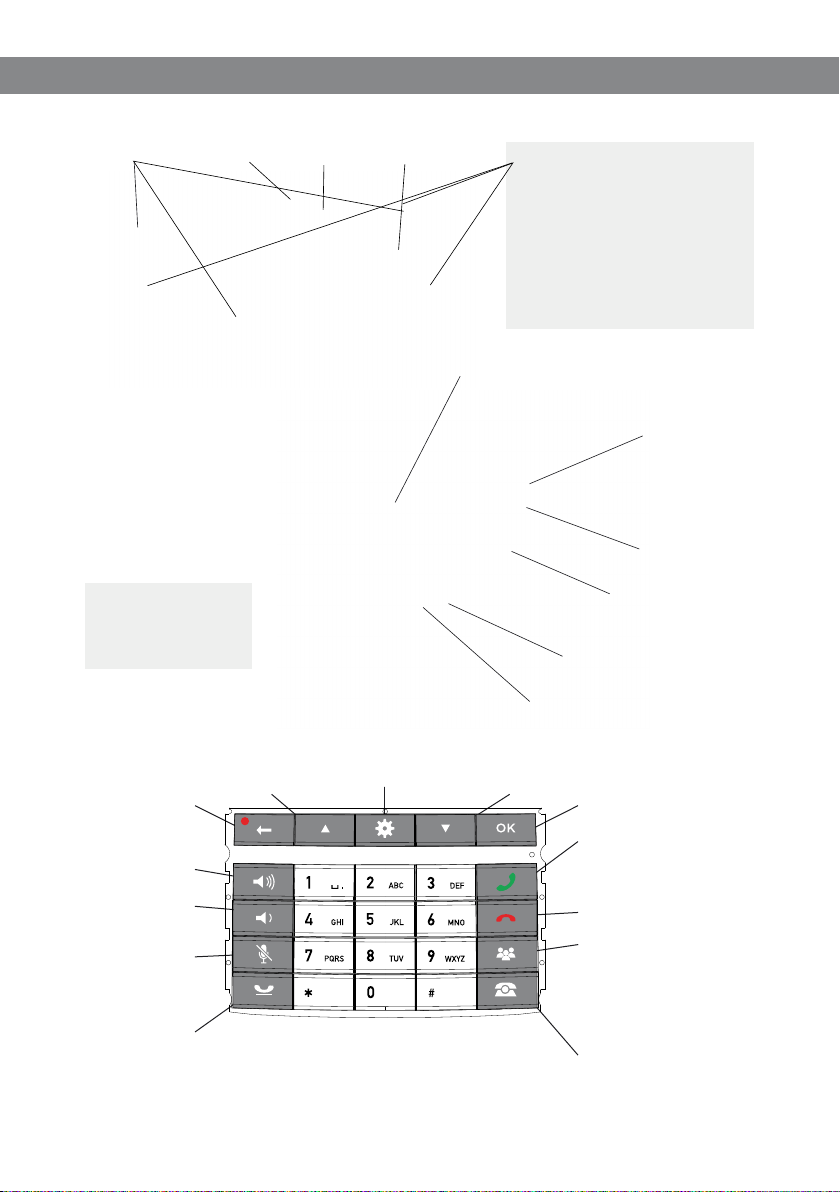
Display screenSpeaker Microphone Key pad
LEDs
Flashing blue Incoming call
Steady blu e light Call in pro gress
Flashing re d On hold,
Steady red l ight Mute,
Network cable port
SD memor y card port
Power suppl y port
Expansion microphone port
microphone and
speakers turned o
microphone turned
o
Expans ion
microphone
port
AUX por t
Security lock port
UP ARROW
Navigati on in menus
Display of c all list
Cancel
No/end/back
Start /stop
recording
Increase volume
Decrease volume
Mute
Hold
S ome Avaya B179 have a di erent keypad with ot her symbols. Th is does not aect th e functions of the b uttons.
Hold dow n a button for 2 secon ds to
Menu
Settings
Alphanumerical buttons
open the phonebook
DOWN ARROW
Navigati on in menus
Display of c all list
OK
Yes/conrm choice
Answer/connect new line
During a call: Press to c all a
new person
Hang up/end line
Conference
Automatic d ialling of
conference groups
One press o f this button will
always conn ect all
parti es to a conference call
Line selection
2
Avaya B179 SIP Conference Phone Installation and Administration Guide
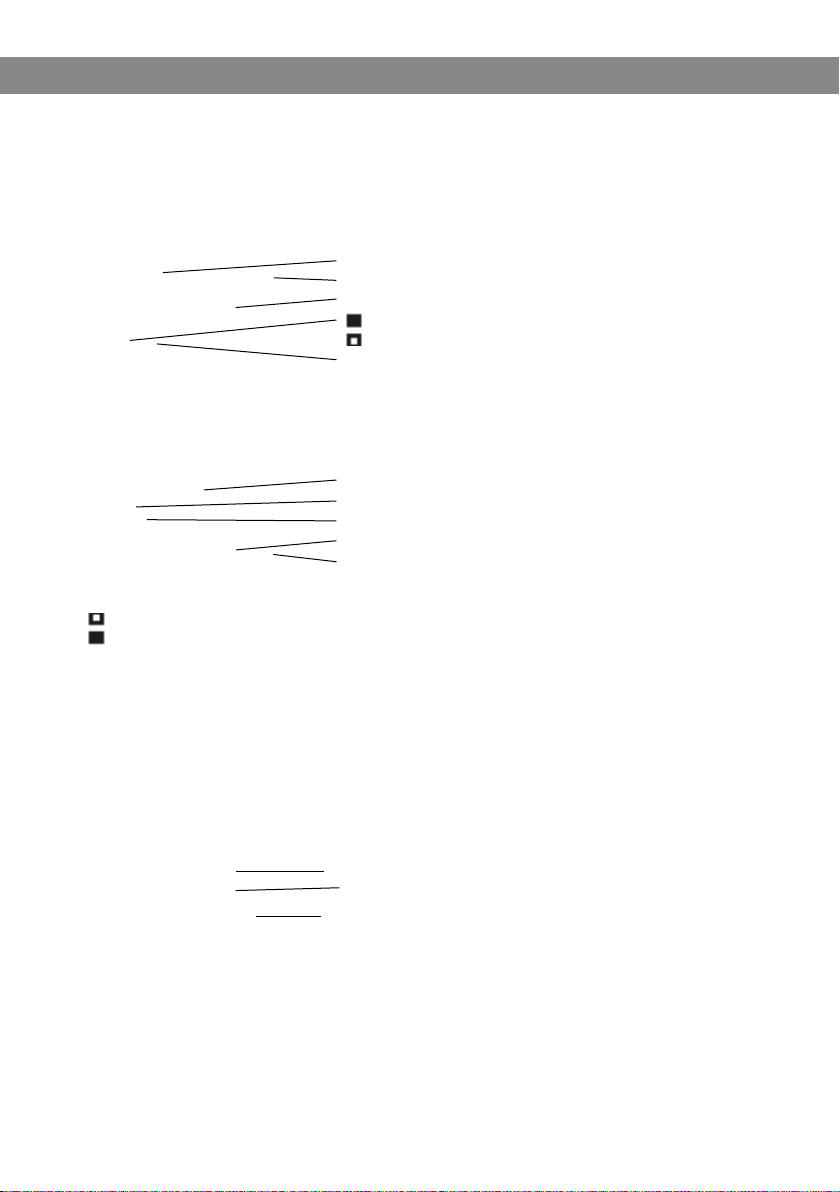
DISPLAY SCREEN
On Hook
Press to display this screen.
Date
Time
Display text (can be changed)
Registered
Not registered
Account name (can be changed)
O Hook
Press to display this screen.
Informa tion text (see bel ow)
Phone line s (L1–L4)
Line stat us (see below)
Call duration
Secure connection
Line status:
Line fre e (Before account name – t elephone not reg istered)
Line connected (Before account name – telephone registered)
Informa tion text displays o ne of the following :
• Number or nam e of each phone line
(The na me will be displayed i f a number is in the phon e book)
• Explanati on of what you should do (F or example, ENTER NUMBER)
• Status (For exam ple Hold when you pl ace all calls on hold)
Line menu
Press to switch to and from this menu.
Line/number/name
New line
Option for creating or splitting conference calls
3

Avaya B179 SIP Conference Phone Installation and Administration Guide
Menu
Press to switch to and from a menu.
Current menu
Submenu
Marked op tion – open by pressin g OK button
Scrolling list
(indicat ion of where the marke d option is in the list o r menu)
List of set ting options:
Existing settings
Marked op tion – select by pr essing OK button
List of names:
Marked na me – select by press ing OK button
NAVIGATION AND SELECTION IN MENUS
Press .
Select the option you want from the menu using the arrow buttons.
Conrm by pressing OK to select the marked option.
Cancel the setting or go back one level in the menu by pressing .
Quit the menu by pressing again.
Note that after you have made changes to a setting, you must press OK to activate the
setting.
It is possible to open a menu option directly by pressing the number button that
corresponds to the position of the option in the menu (For example, 2 to open PHONE
BOOK and then 3 to select EDIT CONTACT).
Writing style in instructions
In the instructions, > SETTINGS (6) means you should:
Press .
Mark the SETTINGS option using the arrow buttons and conrm by pressing OK to open
the menu (or press button number 6).
Correspondingly, Phone book > Conference Guide in the web interface means you should
select Menu Phone book and the Conference Guide tab.
4

Avaya B179 SIP Conference Phone Installation and Administration Guide
Menu tree
Menu tree, advanced settings
The advanced settings are protected by administrator’s PIN code. The default value is 1234.
The simplest way to make settings and edit contacts is using a PC and the Avaya B179 web
interface.
5

Avaya B179 SIP Conference Phone Installation and Administration Guide
USING THE WEB INTERFACE
You can use the web browser of a PC connected to the same network to manage contacts,
conference groups and settings in the Avaya B179. Users can import and export contacts and
conference groups, name user proles, and change PIN codes by using the web interface.
All settings on the Avaya B179 can also be managed via the web interface. You can also view
logs, update software, and create a conguration le to use for other phones.
The values set by using the web interface overrides the local settings on the phone and
the values set by using the settings le.
The default setting for the PIN code is 0000 for the user account (Default, Prole 1, Prole 2,
Prole 3 and Prole 4) and 1234 for the administrator’s account (Admin). You must change the
PIN codes in order to protect the settings. The code may consist a maximum of eight digits.
The administrator can always view and change the PIN codes to the user accounts. The
administrator’s PIN code can only be reset with a complete reset to factory settings.
The existing value of PIN codes are retained after rmware upgrade.
Disabling the web interface
You can disable the web interface on the B179 conference phones to restrict network-based
access to the conference phones. When you congure the phone to disable the web interface,
the HTTP server application on the phone is disabled, and the users cannot access the web
interface.
Note:
You can enable the web interface on a phone from the phone UI. The local web
interface can be used for debugging, but the phone cannot be accessed
over the network.
In the www tag in the global conguration le, set the < /e n a ble > tag to false.
Syntax:
<enable>false</enable>
</www>
Set the Web Interface option in the phone UI to DISABLE WEB.
Press and select the sub menu > ADVANCED (requires Admin password) > WEB
INTERFACE > DISABLE WEB.
You can use the conguration le of the phone to edit the phone settings.
For more information, see topic Using a conguration le.
<www>
6
Avaya B179 SIP Conference Phone Installation and Administration Guide
INSTALLATION
The printed Installation Guide provides brief and simplied installation instructions.
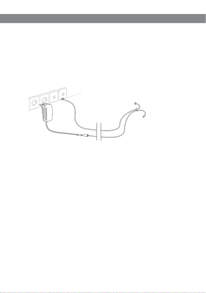
CONNECTING
Connect the Avaya B179 to the network as illustrated below.
Plug the Avaya B179 into the mains using the power adapter as illustrated below.
The Avaya B179 can be driven directly from the network (Power over Ethernet, ClassIII) if
the network supports this.
Place the conference phone in the middle of the table.
The Avaya B179 must obtain a network address and be registered in a SIP PBX before it can be
used. The easiest way to register an account and make the settings in the Avaya B179 is using
a computer connected to the same network and via the integrated web server.
7

Avaya B179 SIP Conference Phone Installation and Administration Guide
OBTAINING A NETWORK ADDRESS
Connecting to a network with DHCP
After the B179 Conference Phone connects to a DHCP network, the phone requests for the
network parameters.
To enable DHCP:
In the web UI, go to Settings > Network. Set the DHCP option to Enabled.
In the phone UI, Press
password) > Network > IP > DHCP. Set the DHCP option to On.
and select
DHCP Site-specic option (SSON)
You can assign the values of site-specic conguration parameters by using DHCP SSON.
You can enable SSON by any of the following methods.
Open the conguration le in an editor. In the <dev_mgmt> tag, set the value of the
<dhcp_option> parameter.
In the web interface of the phone, go to Settings > Provisioning > DHCP Option.
In the phone UI, Press
password) > Network > DHCP Option.
The default value for DHCP SSON is 242. B179 supports SSON from 128 to 254, and option
60 for backward compatibility.
and select
Settings > Advanced (requires the Admin
Settings > Advanced (requires the Admin
8

Avaya B179 SIP Conference Phone Installation and Administration Guide
Connecting to a network with static IP addresses
You need the IP address, host name, domain, netmask, gateway, DNS 1, and DNS 2. The host
name can be set freely. The domain and secondary DNS can be left blank.
Press and select SETTINGS > ADVANCED (6,2).
Enter the PIN code.
The default code is 12 34.
Select NETWORK (2)
Select IP.
Select STAT IC IP.
Enter values for the IP ADDRESS.
Enter three digits (begin with 0 if necessary), press OK, enter three digits, and so on.
Enter HOST NAME
Default is avaya.
Enter DOMAIN
Enter NETMASK
Enter GATEWAY
Enter DNS 1
Enter DNS 2
The display shows DONE.
9
Avaya B179 SIP Conference Phone Installation and Administration Guide
Checking IP address
Press and select the sub menu STATUS > NETWORK (8,2).
Check the conference phone’s network address under the heading IP ADDRESS.
Use this address to log into the web server in the conference phone.
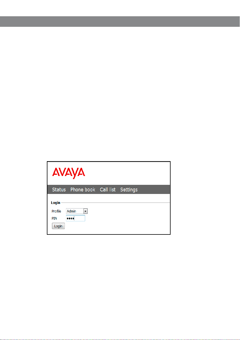
Login
Log into the web server in Avaya B179 by entering the phone’s network address in your
computer’s web browser.
Select Admin as Prole and enter your PIN. The default PIN for Admin is 1234.
10

Avaya B179 SIP Conference Phone Installation and Administration Guide
SOFTWARE UPGRADE AND BASIC SETTINGS
The following settings should be done during installation.
See Device management, if you are responsible for installing or upgrading many phones.
Note that all settings on the Basic tab also aect the user prole Default. Other user proles
can be changed individually. The settings on the Basic tab, except the name and PIN for
Admin, can be modied by any user. Other settings require a login as Admin.
Upgrade software
See the heading “PROVISIONING – UPGRADE AND CONFIGURATION” for a detailed
description and upgrading options.
Select Settings > Provisioning.
11

Avaya B179 SIP Conference Phone Installation and Administration Guide
Compare the latest version with the current version (shown on the web page).
If you want to upgrade, select the desired version in the list box and click on Upgrade.
The browser window and the display on the Avaya B179 shows that the upgrade has begun.
The download and installation can take several minutes. Do not interrupt the upgrade
and do not disconnect plugs to the Avaya B179 during the upgrade. Interrupting the
upgrade may render the conference phone inoperable.
When installation is complete, the text “Upgrade Complete. The unit will be
rebooted.” is shown in your browser, and after a while you hear the Avaya music
signature, which indicates that the conference phone has started.
Setting time and region
Select Settings > Time & Region.
Select the time zone and, if you wish, correction for DST (Daylight saving).
You can set the time and date manually or choose a dierent time server.
Select the region where you are.
This setting aects the frequency and duration of the signaling tones (ring signal, busy
tone, etc).
Save the setting.
The Avaya B179 restarts to apply the new settings.
12

Avaya B179 SIP Conference Phone Installation and Administration Guide
Changing the language
Select Settings > Basic.
Select the desired language in the list box after Language and save the setting. The
B179 Phone supports the following languages:
English
Swedish
Danish
Norwegian
Finnish
Italian
German
Spanish
Portuguese (Br)
Portuguese (Eu)
13

Avaya B179 SIP Conference Phone Installation and Administration Guide
French
Dutch
Cyrillic
Polish
Turkish
Greek
Simplied Chinese
Japanese
Korean
Note, selecting a language only aects the phone language, not the language on the web
interface.
14

Avaya B179 SIP Conference Phone Installation and Administration Guide
Changing the PIN
You must change the PIN code for Admin from the default setting to protect the settings.
Make a note of the new PIN code and keep it in a safe place. The administrator’s PIN code
can only be reset by a full factory reset!
Select Settings > Basic and click the Edit button on the Admin line.
Enter a new PIN.
The PIN code may consist a maximum of 8 digits.
Click on the Set and Save buttons.
REGISTERING AN ACCOUNT
The conference phone supports three accounts. The secondary and fallback accounts are
automatically used if the phone fails to register to the main account. If the phone fails to
register to the secondary or the fallback account, it tries to use the main account again.
To register your phone, you must have access to the account information and all
necessary settings that the SIP PBX requires.
See topic Settings > SIP for a detailed description of all settings.
Procedure
Under Main account, Click Yes at Enable account.
Enter the account information you have received.
Account name can be chosen freely and is the name or phone number you want to
appear in the phone display.
Leave the default values if you have no other information.
Select a method of NAT traversal if you have received this information.
Select a dierent transport protocol if you have received this information. See page 28
about using a secure transport protocol.
Save the settings by clicking the Save button.
The Avaya B179 responds by showing REGISTERING. If registration is successful, your selected
account name will appear at the bottom of the display screen next to a shaded square.
Media settings
Select a dierent codec priority, if you do not accept the default settings.
Select SRTP and SRTCP if you need a secure media protocol. Note that this also requires
a corresponding transport setting on the SIP tab.
15

Avaya B179 SIP Conference Phone Installation and Administration Guide
SETTINGS
You can use the web interface for the settings that can be done directly on the B179 Phone.
See “NAVIGATION AND SELECTION IN MENUS” for using the menu system.
For safety reasons, recordings can only be managed directly on the Avaya B179. All other
settings can be changed via the web interface. The web interface also allows you to import
and export contacts and conference groups, rename user proles and change PIN codes. As
an administrator, you can also study logs, upgrade the software and create an XML based
conguration le for easier management of a set of phones.
BASIC
Select Settings > Basic.
16

Avaya B179 SIP Conference Phone Installation and Administration Guide
To change the basic settings of a user prole, you must log in with that prole.
Proles – edit name and PIN
You must change the PIN code from the default setting to protect the settings.
Select Settings > Basic and click the Edit button on the account you want to change.
Enter a new PIN code.
The PIN code may consist of 8 digits.
You can also choose to change the name of a user prole.
Click on the Set and Save buttons.
Make a note of the new PIN code and keep it in a safe place.
The administrator’s PIN code can only be reset with a complete reset to factory settings!
Language
Select phone language using the list box and click on the Save button.
On phone: > SETTINGS > BASIC > LANGUAGE (6 ,1,1).
Ring level
There are six volume levels plus a silent mode. You will hear the ring tone for each level you
select. If you select silent mode, only the blue LEDs on the phone ash when an incoming call
is received.
Select level using the list box and click on the Save button.
On phone: > SETTINGS > BASIC > RING LEVEL (6,1, 3).
Key tone
You can select whether or not you want a tone to be heard when you press a button.
Select On or O and click on the Save button.
On phone: > SETTINGS > BASIC > KEY TONE (6 ,1,2).
Recording
It is possible to turn o the recording feature. This setting can only be done by the
administrator and aects all proles.
Select On or O and click on the Save button.
For security reasons, recordings can only be managed directly on the SD card on Avaya B179.
Do not remove the SD card during call recording or playback.
17

Avaya B179 SIP Conference Phone Installation and Administration Guide
Recording tone
A short beep is heard every 20 seconds so that all the parties in the call know it is being
recorded. This feature can be turned o.
Select On or O and click on the Save button.
On phone: > RECORDING TONE > SETTINGS (5,5).
Settings when connecting external equipment (Aux)
The Avaya B179 can be connected to a wireless headset or an external PA system. An optional
PA interface box is required for PA system connection.
Select the PA option to activate features for external microphone mixer and PA system.
Do not select the PA option unless a PA system is connected. This option turns o the
internal microphone and internal speakers as default. The HEADSET option may be
selected whether or not a headset is connected.
Time format
Select 12 hour or 24 hour and click on the Save button.
On phone: > SETTINGS > BASIC > TIME FORMAT (6,1,7).
Date format
Select date format and click on the Save button.
On phone: > SETTINGS > BASIC > DAT E FORM AT (6,1,8).
Equalizer
The sound reproduction can be adjusted to the required pitch (SOFT, NEUTRAL or BRIGHT).
Select Soft, Neutral or Bright and click on the Save button.
On phone: > SETTINGS > BASIC > EQUALIZER (6,1,4).
Screen text
The text on the display screen is shown when the Avaya B179 is in stand-by mode (on hook).
Enter your new text in the text box and click on the Save button.
On phone: > SETTINGS > BASIC > SCREEN TEXT (6,1,9).
The table below lists the supported languages for screen text, and the allowed string length.
18

Avaya B179 SIP Conference Phone Installation and Administration Guide
Language String length allowed
English 11
Swedish 9
Danish 10
Norwegian 11
Finnish 12
Italian 13
German 11
Spanish 14
Portuguese (Br) 13
Portuguese (Eu) 14
French 11
Dutch 11
Cryllic 14
Polish 16
Turkish 11
Greek 14
Simplied Chinese 4
Japanese 9
Korean 6
19

Avaya B179 SIP Conference Phone Installation and Administration Guide
SIP
Select Settings > SIP.
20

Avaya B179 SIP Conference Phone Installation and Administration Guide
The conference phone supports three accounts. The secondary and fallback accounts are
automatically used if the phone fails to register to the main account. If the phone fails to
register to the secondary and the fallback accounts, it tries to use the main account again.
Main account, Secondary account, and Fallback account
Enable account It is possible to store account information for future use, but tempo-
rarily disable it.
Account name This is the name displayed on the screen. It can be set according to
company standards.
User The account (customer) name.
Registrar Shall contain the IP address or the public name of the SIP server
where the account is registered (e.g. 10.10.1.100 for a local SIP server
or sip.company.net for a public VoIP service provider)
Proxy Shall contain the proxy server used for Internet communication, if
any. Can be left blank.
Realm The protection domain where the SIP authentication (name and
password) is valid. This is usually the same as the registrar. If marked
with a “*”, the phone will respond to any realm. If specied, the phone
will only respond to the specic realm when asked for credentials.
Authentication name The name used for the Realm authentication. This may be the same as
the user name, but must be lled in.
Password The password used for the Realm authentication.
Registration Interval This is a request to the SIP server for when the registration should
expire. Avaya B179 automatically renews the registration within the
time interval if the phone is still on and connected to the server. The
default value is 1800 seconds.
On phone: > SETTINGS > ADVANCED > (PIN) > ACCOUNTS (6 ,2,1).
Nat traversal
NAT (Network Address Translation) is a rewall or router function that operates by rewriting
the IP addresses in the IP headers as packets pass from one interface to the other. When a
packet, for example, is sent from the inside, the source IP address and port are rewritten from
the private IP address space into the address space on the outside (Internet).
NAT rewrites the addresses but leaves the packets themselves untouched. This kind of translation works ne for many protocols, but causes a lot of trouble for SIP packets that contain
address information in their content (for example an INVITE request from one IP address to
another).
NAT traversal solves this problem, providing a “view from the outside” that makes it
21

Avaya B179 SIP Conference Phone Installation and Administration Guide
possible to replace the IP address in the SIP requests with the address shown on the other
side of the rewall.
Note that in some cases NAT traversal is not necessary. Some public service providers of IP
telephony keep track of the actual IP address used to register a phone, and the one used in
the SIP requests from the same phone, and then replaces the addresses in the SIP messages.
STUN STUN (Simple Traversal of UDP through NATs) is a protocol that assists
devices behind a NAT rewall or router with their packet routing.
STUN is commonly used in real-time voice, video,
messaging, and other interactive IP communication applications.
The protocol allows applications operating through a NAT to
discover the presence and specic type of NAT and obtain the
mapped (public) IP address (NAT address) and port number that the
NAT has allocated for the application’s User Datagram Protocol (UDP)
connections to remote hosts. The protocol requires assistance from a
3rd-party network server (STUN server).
STUN should be activated if an external SIP server cannot connect
to the Avaya B179 behind a rewall NAT function and the SIP server
supports STUN. A suitable STUN server is usually provided by the VoIP
service provider.
Note: STUN might also be referred to as Session Traversal Utilities for
NAT.
STUN host The IP address or public name of the STUN server.
Oer ICE ICE (Interactive Connectivity Establishment), is a STUN addition that
provides various techniques to allow SIP-based VoIP devices to successfully traverse the variety of rewalls that may exist between the
devices. The protocol provides a mechanism for both endpoints to
identify the most optimal path for the media trac to follow.
TURN TURN (Traversal Using Relay NAT) TURN is an extension of the STUN
protocol that enables NAT traversal when both endpoints are behind
symmetric NAT. With TURN, media trac for the session will have to
go to a relay server. Since relaying is expensive, in terms of bandwidth
that must be provided by the provider, and additional delay for the
media trac, TURN is normally used as a last resort when endpoints
cannot communicate directly.
TURN User User authentication name on the TURN server.
TURN host The IP address or public name of the TURN server.
Password User authentication password on the TURN server.
On phone: > SETTINGS > ADVANCED > (PIN) > NAT TRAVERSAL (6,2,3).
22

Avaya B179 SIP Conference Phone Installation and Administration Guide
Advanced
Enable SIP Replaces Default is Yes. Setting this option to No, will instruct the PBX not to
use the SIP replace header. Some PBXes try to take over the bridging
functionality from Avaya B179 using this command, which causes the
calls to interrupt.
Enable Blind Transfer Default is Yes. Setting this option to No, will disable the transfer func-
tion (
> TRANSFER) during a call. This may be used if the PBX does not
support blind transfer.
Allow contact rewrite Default is Yes. When enabled, the B179 will store the IP address from
the response of the register request. If a change is detected, the
phone will unregister the current sip URI (contact), and update the sip
URI with the new address.
Send media ‘inactive’ Default is No. Must be set to Yes in a CS1000 server environment.
instead of ‘sendonly’
on hold
Outbound proxy The IP address of the outbound proxy server.
Conference server The IP address of the conference server that is currently in use.
Accept-Language header
value Indicates the preferred languages for reason phrases, session
descriptions, or status responses carried as message bodies in the SIP
response.
Transport
The transport setting only concerns the protocol to be used for SIP messages between the
devices involved. These settings do not include the media (the actual call). The settings on the
Media tab should be set accordingly.
Note that if you choose to use a secure connection, both units must support it. Otherwise
they cannot negotiate a connection. If an incoming call demands a secure TLS or SIPS connection, the Avaya B179 uses the appropriate protocol even if you have set the phone to use UDP.
Protocol UDP (User Datagram Protocol) is a protocol on the transport layer
in the Internet Protocol Suite. It is a stateless protocol for short messages – datagrams. Stateless implies that it does not establish any
connection between sender and receiver in advance. UDP does not
guarantee reliability or ordering in the way that TCP does. Datagrams
may arrive out of order or go missing without notice. The advantages
it oers are speed and eciency.
UDP is the default protocol for SIP.
TCP (Transmission Control Protocol) is a protocol on the transport
layer in the Internet Protocol Suite. TCP is the standard protocol for
23

Avaya B179 SIP Conference Phone Installation and Administration Guide
Internet communication. TCP keeps track of all individual packets
of data, ensuring that they reach the receiver and are put together
properly. TCP is not the default protocol for SIP, because it is slower
and uses more bandwidth than UDP.
With UDP and TCP, SIP packets travel in plain text. TLS (Tra nsp ort
Layer Security) is a cryptographic protocol that provides security
and data integrity for communications over TCP/IP networks. TLS
encrypts the datagrams of the transport layer protocol in use. The
secure connection may be to the end device or to the rst server
(usually the SIP server where the phone is registered). There is no
guarantee that there is a secure channel to the end point, but because the SIP server is the only part receiving the user authentication,
this is still a rather secure solution.
SIPS (Secure SIP) is a security measure that uses TLS to provide an
encrypted end-to-end channel for the SIP messages. To use SIPS,
however, both VoIP devices and the SIP server must support it.
Even if Transport is set to TLS or SIPS, the Avaya B179 still accepts incoming UDP or TCP
signalling.
On phone: > SETTINGS > ADVANCED > (PIN) > ACCOUNTS > TRANSPORT (6,2 ,1,3).
TLS Settings
If you select TLS or SIPS under the transport setting, an additional setting appears on the
page. The settings are described below.
It may be possible to use secure communication without a certicate and make changes to
these settings. In some cases, if you choose TLS or SIPS, the SIP server requires a certicate for
user/client verication. This should be specied in the account information.
You can further increase security by requiring verication of the server, or the client when the
Avaya B179 acts as a server for incoming calls. For more information, see Appendix C: Using
EAP TLS authentication.
The supported encryptions are SHA-1 and SHA-256 1024 and 2048 bits.
Method The TLS includes a variety of security measures. The methods are
dened in the versions of the standard (SSL, SSL v2, SSL v3, TLS v1, TLS
v2). The default method is SSLv23, which accepts both SSL v2 and v3.
Negotiation timeout The TLS settings are negotiated during a call setup (both incoming
and outgoing). If this negotiation does not succeed within the specied time (seconds) the negotiation is aborted. Timeout is disabled
with 0 (zero).
Verify client When set to On, the Avaya B179 will activate peer verication for
incoming secure SIP connections (TLS or SIPS).
24

Avaya B179 SIP Conference Phone Installation and Administration Guide
Require client certicate
When set to On, the Avaya B179 rejects incoming secure SIP connections (TLS or SIPS) if the client does not have a valid certicate.
Verify server When the Avaya B179 is acting as a client (outgoing connections) us-
ing secure SIP (TLS or SIPS) it will always receive a certicate from the
peer. If Verify server is set to On, the Avaya B179 closes the connection
if the server certicate is not valid.
Certicate Here you can upload a certicate to the Avaya B179 to be used for TLS
or SIPS communication.
A certicate is a le that combines a public key with information
about the owner of the public key, all signed by a trusted third party.
If you trust the third party, then you can be sure that the public key
belongs to the person/organization named in that le. You can also
be sure that everything you decrypt with that public key is encrypted
by the person/organization named in the
certicate.
Root certicate The public key in the root certicate is used to verify other certicates.
A root certicate is only needed if you have selected client or server
verication.
A root certicate is signed by the same public key that is in the certi-
cate, a so-called “self-signed” certicate. A typical root certicate is
one received from a Certicate Authority.
Private key Here you can upload a private key to the Avaya B179 to be used for
TLS or SIPS communication.
A private key is one of the keys in a key-pair used in asymmetric
cryptography. Messages encrypted using the public key can only be
decrypted using the private key.
Private key password Password used for encryption of the private key, if it is encrypted.
25

Avaya B179 SIP Conference Phone Installation and Administration Guide
NETWORK
Select Settings > Network.
26

Avaya B179 SIP Conference Phone Installation and Administration Guide
DHCP Dynamic Host Conguration Protocol is used by network devices
(clients) to obtain the parameters necessary for operation in the IP
network. This protocol reduces system administration workload,
allowing devices to be added to the network with little or no manual
conguration.
DHCP should be set to On if no other information is given. When set
to On, all information on this page will be set automatically.
IP address IP address of the device (Avaya B179). The address is provided by the
network administrator or service provider if DHCP is not in use.
Hostname Set to avaya as default. Can be changed to suitable name.
Netmask Usually set to 255.255.255.0 to limit network trac to the subnet.
Domain The domain where the device is located. May be left blank.
Gateway The device or server used for Internet communication.
Primary DNS The address to the primary DNS (Domain Name System) server - a
program or computer that maps a human-recognisable name to its
computer-recognisable identier (IP address).
Secondary DNS The address of an optional secondary DNS server.
On phone: > SETTINGS > ADVANCED > (PIN) > NETWORK (6,2,2).
Quality of Service
Quality of service is used in IP networks to provide dierent priority to dierent applicaions,or
to guarantee a certain level of performance to a critical data ow such as voice or video.
Dierentiated Services or DiServ is a networking architecture that species a simple mechanism for classifying network trac using a 6-bit eld in the header of the IP packets. VLAN
(Virtual LAN) is a technology to logically divide a physical network into several logical nets
and thus to dierentiate trac.
SIP DiServ Enter a value between 0 and 63 to prioritize the SIP messages.
Media DiServ Enter a value between 0 and 63 to prioritize the media packets (voice).
VLAN By enabling this option, all communication to and from Avaya B179 is
done via the VLAN specied under VLAN ID. Note that this VLAN also
must be used to communicate with Avaya B179 via the web interface.
VLAN ID The ID number to be used for the IP telephony VLAN.
VLAN map enable Enabling VLAN priority mapping from the DiServ setting.
VLAN prio SIP Set a value between 0 and 7 to prioritize the SIP messages in the
VLAN.
VLAN prio media Set a value between 0 and 7 to prioritize the media packets in the
VLAN.
27

Avaya B179 SIP Conference Phone Installation and Administration Guide
On phone: > SETTINGS > ADVANCED > (PIN) > NETWORK > ETHERNET > VLAN (6,2,2,2,1).
802.1x
IEEE 802.1X is an IEEE Standard for port-based Network Access Control and is part of the IEEE
802.1 group of networking protocols. It provides an authentication mechanism to devices
wishing to attach to a LAN or WLAN.
Enable 802.1x By enabling this option, Avaya B179 asks an authentication server for
permission when connected to the LAN.
EAP method Select which EAP (Extensible Authentication Protocol) method to use:
MD5 or TLS.
Username The device identity in the network.
MD5 password Password for the device identity when using MD5.
Certicate Here you can upload a certicate to the Avaya B179 to be used for
authentication when using TLS.
Root certicate The public key in the root certicate is used to verify other certicates
when using TLS.
Private key Here you can upload a private key to the Avaya B179 to be used for
authentication when using TLS.
TLS password The password used for encryption of the private key when using TLS.
On phone: > SETTINGS > ADVANCED > (PIN) > NETWORK > ETHERNET >
802.1X AUTH (6,2,2,2,2).
28

Avaya B179 SIP Conference Phone Installation and Administration Guide
MEDIA
Select Settings > Media.
The media settings determine how audio is sent between the devices. The devices negotiate via SIP before a call is connected. All devices must support the same media types,
codecs and security settings.
29

Avaya B179 SIP Conference Phone Installation and Administration Guide
Codec
Codecs are used to convert an analog voice signal to a digitally encoded version and vice
versa. Codecs vary in the sound quality they deliver and the bandwidth required. The Avaya
B179 supports the most common codecs and each codec can be given a precedence depending on your requirements for high quality audio or low bandwidth use.
The priority can be set to from 4 (high) to 1 (low) or 0 (disabled)
G722 G.722 is an ITU-T standard codec that provides 7 kHz wideband audio at
a data rate within 64 kbit/s. It oers greately improved speech quality
compared with older narrowband codecs such as G.711, but requires
a high quality network connection between the devices.
G711 Alaw G.711 is an ITU-T standard codec that uses audio companding.
Companding algorithms reduce the dynamic range of an audio
signal. In analog systems, this can increase the signal-to-noise ratio
achieved during transmission and, in the digital domain, can reduce
the quantization error.
Two main compression algorithms are dened in the standard,
the µ-law algorithm (used in North America and Japan) and A-law
algorithm (used in Europe and the rest of the world).
G711 Ulaw See G711 A-law above.
G729 G.729 is an ITU-T standard codec that operates at 8 kbit/s. It is mostly
used in VoIP applications with low bandwidth requirement.
On phone: > SETTINGS > ADVANCED > (PIN) > MEDIA > CODEC ( 6,2 ,4,1) .
Security
The media in VoIP calls is usually sent using the RTP protocol (Real-time Transport Protocol).
RTP is a standardized packet format for delivering audio and video over the Internet.
SRTP (Secure Real-time Transport Protocol) is an extension of RTP to provide encryption,
message authentication and integrity for the audio and video streams.
All devices must support SRTP to establish a connection. It is therefore possible to set SRTP as
disabled, optional or mandatory.
RTCP can be used to control the RTP session. When using SRTP, the same security-related
features are added to the control protocol. SRTCP (Secure Real Time Control Protocol) can be
either encrypted or not encrypted.
30

Avaya B179 SIP Conference Phone Installation and Administration Guide
SRTP If set to disabled, the media is sent using RTP. Note that despite this
setting, the Avaya B179 will still use a secure channel if the opposite
device demands it.
If set to optional or mandatory, a padlock will be shown in the bottom
right-hand corner of the screen. If the other devices support SRTP, the
padlock will be locked. Otherwise, an open padlock will be displayed.
If set to mandatory, the call will not be connected if the other devices
do not support SRTP.
SRTCP Is automatically used when SRTP is enabled. Can be set to use encryp-
tation or not.
Secure signalling The SIP messages (signalling) and the SRTP cipher key are sent on a
dierent channel than the media and are not aected by the RTP/
SRTP setting. To ensure a secure connection, the signalling must be
secured using TLS or SIPS, see page 20. Note that the SIP transport
setting must be set accordingly.
On phone: > SETTINGS > ADVANCED > (PIN) > MEDIA > SECURITY (6,2,4,4).
RTCP Monitoring
Monitoring Host IP Address of the RTCP monitoring server.
All RTCP packets are sent to this host for monitoring.
If you use SRTP, unencrypted packets are sent to this host.
In the conguration le, update the IP address in the
<rtcp_monitoring_server_host> tag.
Monitoring Port The port of the RTCP monitoring server.
VAD
Voice Activity Detection (speech detection) is a technique used in speech processing to
detect the presence or absence of human speech in regions of audio. In VoIP applications,
VAD is mainly used to avoid unnecessary coding and transmission of silence packets, saving
on computation and network bandwidth.
On phone: > SETTINGS > ADVANCED > (PIN) > MEDIA > VAD (6,2,4,2).
DTMF
DTMF (Dual-tone multi-frequency) signalling is used for telephone signalling over the line to
the phone switch or PBX.
If the device itself generates the tones and they are sent in the voice-frequency band, the
method is called Inband. This is not the best method when using VoIP. Low bit rate
codecs may corrupt the signalling tones and make it dicult for the switch to identify them.
31

Avaya B179 SIP Conference Phone Installation and Administration Guide
RFC 2833 is a method of carrying DTMF signals in RTP packets using a separate RTP payload
format. With this method a PSTN gateway reproduces the DTMF tones sent from the end
device.
With SIP Info the DTMF signals are sent as SIP requests. The SIP switch creates the tones if the
call is transferred to the PSTN.
Use RFC 2833 or SIP Info as preferred methods. Switch to inband only if you encounter problems using DTMF signalling with your PBX/SIP switch.
On phone: > SETTINGS > ADVANCED > (PIN) > MEDIA > DTMF SIGNALLING (6,2,4,3).
Advanced
First RTP port If the RTP packets must be directed to a specic port series, the rst
port number is set here.
32

Avaya B179 SIP Conference Phone Installation and Administration Guide
LDAP
Select Settings > LDAP.
Avaya B179 has support for an external phone book, which means it can communicate with a
directory server using LDAP (Lightweight Directory Access Protocol). The built in search function dynamically lters the content from the LDAP database, based on the search characters
the user enter.
To make the LDAP phone book available, the administrator has to activate and congure the
LDAP feature.
Enable LDAP The LDAP feature is disabled by default because it has to be cong-
ured.
Name lter Denes how the entered search characters are used. The lter is
designed conforming to the string representation of LDAP search
lters described in RFC2254. The character % in the lter string will be
replaced with the search character entered by the user.
Example:
(|(sn=%*)(cn=%*)) - All entries with the search characters in the beginning of the sn OR cn attribute are presented to the user.
Server URL The IP address of the LDAP server host. Supports ldap and ldaps.
Search base The DN (distinguished name) of the search base
Example:
dc=domain, dc=com.
33

Avaya B179 SIP Conference Phone Installation and Administration Guide
Username Leave this eld blank if the LDAP server does not require a username.
Password Leave this eld blank if the LDAP server does not require username
and password.
Max hits The maximum number of hits to return for each LDAP search.
Display name Species how the search hits shall be presented on the display in
Avaya B179.
Example:
%cn - shows the cn attribute.
%givenName %sn - shows the givenName attribute and the sn attribute with a space in between.
Sort results Sorts the search hits based on the Display name.
Number attributes Here you dene the attributes that shall be displayed for a selected
search hit.
Example:
mobile telephoneNumber - shows the mobile phone number and
oce phone number on separate rows for the selected Display name.
(Refer to the LDAP administrator for the actual names of the elds in
the LDAP database.)
Country code By entering the country code where the phone is located, the country
code in any phone number attribute is ignored, if it is identical.
Area code By entering the area code where the phone is located, the area code
in any phone number attribute is ignored, if it is identical.
External prex If a special prex is needed to dial external numbers, it should be
added here. Use this if you for example need to dial 0 to get a dialing
tone.
Min length for external prex
Restricts the external prex to be added only if the phone number
is longer than the min length. This makes it possible to use short
internal numbers.
Exact length for no external prex
The external prex in not added if the phone number has exactly the
entered length.
Number prex for no external prex
All numbers that starts with this number will not have the external
prex added. Useful if you know that all internal numbers start with a
certain number.
34

Avaya B179 SIP Conference Phone Installation and Administration Guide
LLDP
Select Settings > LLDP
Link Layer Discovery Protocol (LLDP) is a data link layer protocol. LLDP denes a standard
for Ethernet network devices to broadcast and receive information about other devices in
the same network. The information is sent as LLDP Data Units (LLDPDU). Each LLDPDU is a
sequence of Time-Length-Value (TLV) strings.
35

Avaya B179 SIP Conference Phone Installation and Administration Guide
The B179 Conference Phone supports LLDP on primary Ethernet interfaces. The following
table lists the TLVs that the B179 Conference Phone supports:
CATE GORY TLV NAME TYPE STRING
TLV INFO STRING VALUE
LENGTH
BASIC MANDATORY CHASSIS ID 6 MAC ADDRESS OF THE PHONE
BASIC MANDATORY PORT ID 7 IP ADDRESS OF THE PHONE
BASIC MANDATORY TIME TO LIVE 2 L LD P_T TL
BASIC OPTIONAL SYSTEM NAME 9 LLDP_SYSTEM_NAME
BASIC OPTIONAL SYSTEM CAPABILITIES 4 BIT 5 PHONE IS SET IN THE
SYSTEM CAPABILITIES OCTET.
IF THE PHONE IS REGISTERED,
BIT 5 IS SET IN THE ENABLED
CAPABILITIES OCTET.
BASIC OPTIONAL MANAGEMENT
ADDRESS
ORGANIZATION
SPECIFIC IEEE 802.3
MA C/PHY/
CONFIGURATION
STAT US
23 MGMT ADDR STRING LENGTH
= 5; MGMT ADDRESS SUBTYPE
= 01; IPV4 MGMT ADDRESS
= IPADD; INTERFACE NUMBER
SUBTYPE = 2; INTERFACE
NUMBER = 3
9 802.3 OUI = 00120F HEX;
802.3 SUBTYPE = 1;
AUTONEGOTIATION SUPPORT/
STATUS = VALUE SENT DURING
AUTONEGOTIATION;
OPTIONAL MAU TYPE =
LLDP_MAU
TIA LLDP MED LLDPMED
CAPABILITIES
7 TIA OUI = 0012BB HEX;
LLDP CAPABILITIES SUBTYPE
= 1;
LLDPMED CAPABILITIES =
0023 INVENTORY, NETWORK
POLICY, MED CAPS;
LLDPMED DEVICE TYPE = 3
CLASS III
36

Avaya B179 SIP Conference Phone Installation and Administration Guide
CATE GORY TLV NAME TYPE STRING
TLV INFO STRING VALUE
LENGTH
TIA LLDP MED NETWORK POLICY
VOICE
TIA LLDP MED INVENTORY
SOFTWARE REVISION
TIA LLDP MED INVENTORY
MANUFACTURER
NAME
TIA LLDP MED INVENTORY MODEL
NAME
BASIC MANDATORY ENDOFLLDPU 0 NA
8 TIA OUI = 0012BB HEX;
NETWORK POLICY SUBTYPE = 2;
APPLICATION TYPE = 1 VOICE
U = 0 NETWORK POLICY IS
DEFINED
T = TAGGIN G
X = 0 RESERVED BIT
VLAN ID = VLAN_IN_USE
5 36 TIA OUI = 0012BB HEX;
SOFT WARE REVISION SUBTYPE
= 7;
SOFTWARE REVISION = VALUE
9
TIA OUI = 0012BB HEX;
MANUFACTURER NAME
SUBT YPE = 9;
MANUFACTURER NAME =
VALUE
8 TIA OUI = 0012BB HEX;
MODEL NAME SUBTYPE = 10;
MODEL NAME =VALUE
37

Avaya B179 SIP Conference Phone Installation and Administration Guide
WEB INTERFACE
Select Settings > Web interface.
The web server in the Avaya B179 supports secure connections using HTTPS.
Enable HTTPS Set Enable HTTPS to On if you need a secure communication between
the PC used for setup and the phone.
Certicate To use HTTPS you must upload a .PEM certicate to the phone.
Note: To convert .DER or .PFX formats to .PEM, use the OpenSSL commands listed in step 6 of
Appendix C on page 84.
Use the following command to generate a HTTPS web interface certicate:
openssl req –new –x509 –keyout https _ web _ certicate.pem –out
https _ web _ certicate.pem –day<number of days> -nodes
On phone: > SETTINGS > ADVANCED > (PIN) > WEB INTERFACE (6,2,7).
38

Avaya B179 SIP Conference Phone Installation and Administration Guide
TIME & REGION
Select Settings > Time & Region.
Time
Enable NTP NTP (Network Time Protocol) is a protocol for distributing the
Coordinated Universal Time (UTC) by means of synchronizing the
clocks of computer systems over packet-switched, variable-latency
data networks.
Time This eld shows the actual time if NTP is enabled. Otherwise enter the
correct time (hh:mm:ss) and save the setting.
Date This eld shows the actual date if NTP is enabled. Otherwise enter the
correct date (yyyy-mm-dd) and save the setting.
Timezone Select the UTC time zone in your country.
39

Avaya B179 SIP Conference Phone Installation and Administration Guide
Daylight saving Select the Yes radio button if DST (Daylight Saving Time or Summer
Time) is currently used in your country. Note that this setting only
adjusts the time by one hour and does not change the time automatically when the DST starts and ends.
NTP Server The NTP pool is a dynamic collection of networked computers
that volunteer to provide highly accurate time via NTP to clients
worldwide. These computers are part of the pool.ntp.org domain and
part of several subdomains divided by geographical zones. They are
distributed to NTP clients via round robin DNS.
On phone: > SETTINGS > ADVANCED > (PIN) > TIME (6,2,5).
Region
Select the region where you are. This setting determines the signalling (disconnect tone, busy
tone, etc).
On phone: > SETTINGS > ADVANCED > (PIN) > REGION (6,2,6).
Daylight saving
Enable DST Select the Yes radio button if DST (Daylight Saving Time or Summer
Time) is used in your country.
DST Timezone Select the oset from UTC time when daylight saving is in use.
DST Mode When set to Automatic, OmniTouch 4135 IP uses dates stored in the
phone to adjust for DST. When set to Manual, you need to manually
set the oset two times a year.
Start/Stop xed date Set to Yes if DST changes the same date every year in your country.
Then select the time and date it changes.
Set to No if DST changes a specic week and day each eyar. (For
instance third sunday in March.) Then select the month, week and
time it changes.
PROVISIONING
See “PROVISIONING – UPGRADE AND CONFIGURATION” on page 46.
SYSTEM
Select Settings > System.
40

Avaya B179 SIP Conference Phone Installation and Administration Guide
Application restart
The Restart button restarts the phone application. This takes less than 30 seconds.
On phone: > SYSTEM > RESTA RT ( 7,1).
System reboot
The Reboot button reboots the conference phone. The starting procedure may take about
two minutes.
On phone: > SYSTEM > REBOOT (7, 2).
Factory reset
The Reset button resets the Avaya B179 to factory default settings. All personal settings,
including account information, are erased.
On phone: > SYSTEM > FAC TORY RE SET ( 7,3).
Hard reset to factory settings
See the information about resetting the phone if you have forgotten the Admin PIN code.
41

Avaya B179 SIP Conference Phone Installation and Administration Guide
CONNECTING A WIRELESS HEADSET
Connect the headset to the Aux port on Avaya B179.
The microphones from the Avaya B179 and the wireless headset will work simultaneously and
transmit the call to other participants in the phone conference.
Please refer to the headset manual for further information.
Turning o the internal speakers when using a headset
The internal speakers can be turned o temporarily if you wish to use the Avaya B179 as a
personal telephone with a headset.
During a call, select > HEADSET.
Select YES when asked “SPEAKER OFF?”.
The speakers come on automatically when the call is ended.
42

Avaya B179 SIP Conference Phone Installation and Administration Guide
HEADSET AND PA INSTALLATION AND SETTINGS
CONNECTING A PA INTERFACE BOX
The Avaya B179 can be connected to an external PA system using a PA interface box.
To amplier/speakersTo mixer/microphone2.5 m conn ection cable
PA interface b ox
AUX por t
Always disc onnect the power s upply from the ele ctrical outlet before disconnecting or connecting
equipme nt to the Avaya B179.
Connect the PA-box to the AUX port on Avaya B179 with the included cable.
Connect the external amplier to the RCA connector marked with a speaker.
Connect the microphone mixer to the RCA connector marked with a microphone.
Changing the auxilary port setting
Select Settings > Basic.
Select PA under the heading Auxilary port to activate the functions for external
microphones and speaker system.
Click on Save.
Do not select the PA option unless a PA system is connected. This option turns o the
internal microphone and internal speakers as default.
On phone: > SETTINGS > BASIC > AUX PORT (6,1,5).
PA SET TINGS
To match several types of situations and equipment, there are some settings available in the
Avaya B179 menu.
Activating internal microphone and speakers
These settings are not available via the web interface.
Select > SETTINGS > BASIC > PA (6,1,6).
43

Avaya B179 SIP Conference Phone Installation and Administration Guide
Select INTERNAL MIC and press OK to switch between on (shaded box) and o.
To ensure maximum audio quality, do not use the internal microphone and external
microphones connected via the PA box at the same time.
Only the internal microphone is turned o. Any external microphones connected to the
Avaya B179 are still turned on.
Select INTERNAL SPKR and press OK to switch between on (shaded box) and o.
To ensure maximum audio quality, do not use the internal speakers and external speakers
connected via the PA box at the same time.
Adjusting microphone volume from PA
During a call, select > PA > PA MONITOR.
Adjust the microphone volume from the mixer so that the level on the display screen is
around 10–12 when speaking in a normal tone.
Adjusting PA calibration manually
It is possible to calibrate the duplex performance of the conference phone when it is connected to a PA system. The calibration level can be set automatically by the Avaya B179 or
adjusted manually to any value between 0 and 5 (0 being full duplex).
• Increase the calibration if the other party experiences disturbing echo.
• Decrease the calibration if the other party experiences low duplex, i.e. your voice is muted
or clipped when the other party is speaking.
The position of the PA system’s microphones and speakers and the amplier’s settings
may aect full duplex performance.
Select > PA > CALIBRATION.
NB. You must ask the person you are calling to assess the eect of the adjustments you
make.
AUTO is the default setting. The gure shown in brackets is the measured calibration
value.
Select dierent levels and compare the audio quality to achieve your preferred setting.
44

Avaya B179 SIP Conference Phone Installation and Administration Guide
45

Avaya B179 SIP Conference Phone Installation and Administration Guide
HARD SYSTEM RECOVERY
Reset conguration
If you have forgotten the Admin PIN code, the only way to reset it to default is to do a hard
factory reset. This is the same as the Factory reset in the system menu (
RESET).
This erases all settings including account information and contacts!
Disconnect the power supply cable. Note that this is the same as the network cable if the
phone uses Power over Ethernet.
Press and hold the button while you connect the cable again (Restarts the Avaya B179).
Hold the button pressed until the SYSTEM RECOVERY menu is shown on the display.
You can press any other button than 1, 2, or 3 to start the phone without resetting.
Press 1 to select Reset conguration and conrm with OK.
Upgrade to the latest version of the software when the phone has started and redo the
setup of account and other settings.
Restore rmware
This replaces the current software with the one supplied with the phone. All settings are
erased.
Export a conguration le if local settings should be saved and export the contacts if
these are stored in the unit.
Disconnect the power supply cable. Note that this is the same as the network cable if the
phone uses Power over Ethernet.
Press and hold the button while you connect the cable again (restarts the Avaya B179).
Hold the button pressed until the SYSTEM RECOVERY menu is shown on the display.
You can press any other button than 1, 2, or 3 to start the phone without restoring the
rmware.
Press 3 to select Restore rmware and conrm with OK.
All content in the phone’s memor y is erased and the rmware supplied with the phone is written to
the memory.
Upgrade to the preferred version of the rmware when the phone has started.
Import the local conguration and previous contacts or do a manual account setup.
> SYSTEM > FACTORY
46

Avaya B179 SIP Conference Phone Installation and Administration Guide
PROVISIONING UPGRADE AND CONFIGURATION
FIRMWARE UPGRADE ON A SINGLE PHONE
The easiest way to upgrade the Avaya B179 is via a computer connected to the same network.
Via the web interface, you can check for a more recent version and then automatically install
it.
It is also possible to download the latest version, via the Avaya website (support.avaya.com),
and then install the le via the web interface or using a SD card.
Using the web interface
Select Settings > Provisioning.
Upgrading from downloaded le
It is possible to download a rmware le from support.avaya.com and install it on the Avaya
B179 from the local hard disk.
Download the rmware le from support.avaya.com.
Click on the Browse… button and locate and select the downloaded le.
Click on the Upgrade button.
Upgrading from SD card
Upgrading from SD card may be suitable if you have many phones to upgrade. The phones
do not have to be connected to the network.
Download the latest rmware as above and save it on a SD card.
Put the SD card in the phone you want to upgrade.
Disconnect the power supply cable. Note that this is the same as the network cable if the
phone uses Power over Ethernet.
Press and hold the button while you connect the cable again (i.e. starts the Avaya
B179). Hold the button pressed until the SYSTEM RECOVERY menu is shown on the display.
You can press any other button than 1, 2, or 3 to start the phone without any change.
Press 2 to select SD-card upgrade.
The Avaya B179 is upgraded with the rmware le on the SD card and starts when the upgrade is
done.
After upgrading
If DHCP is used in the network, the IP address may have been changed. If the web browser
loses contact with Avaya B179, check the IP address on the conference phone, see USING THE
WEB INTERFACE.
47

Avaya B179 SIP Conference Phone Installation and Administration Guide
DISABLING FIRMWARE UPGRADE FROM SD CARD
To disable the rmware upgrade from the SD card, set the <sd_upgrade_disabled> tag in the
global conguration le to true.
Note: You cannot enable the rmware upgrade from the SD card after it is disabled.
The recovery process prompts to initiate the SD card-based rmware upgrade even if the
option is disabled in the conguration le. When the user selects the option to initiate the
upgrade, the following messages are displayed:
SD-card upgrade. Please wait.
SD-Upgrade disabled. Skipping upgrade.
FIRMWARE UPGRADE ON MULTIPLE PHONES
To upgrade the rmware on multiple B179 conference phones, use a device management
server.. For information about conguring and using a device management server, see Using
a device management server on Page 58.
48

Avaya B179 SIP Conference Phone Installation and Administration Guide
You can save a conguration xml le to be used as:
• Backup (i.e. if the system has been reset to factory default)
• Conguration interface (there are some settings that are not congurable via the web
interface)
• Management tool (export, edit and import settings to a set of phones instead of doing
the settings on each phone)
• Use with a Device Management server, see page 48.
The structure of the xml le is as follows:
<locale>
<region>
<recording>
<enable>
<logging>
<level> The phone application logs messages to log facility LOCAL0.
<log_sip> Log SIP messages to log facility LOCAL1. Default is true.
<remote_log> Log messages to a remote log server. Default is false.
<remote_host /> Remote log server.
<network>
<net>
<dhcp> Specif y if DHCP should be used to obtain network settings. If so, the other
<ip> Specify the IP address of the Avaya B179.
<netmask> The netmask of the IP address.
<gateway> Specif y the default gateway to be used.
<dns1> Specify at most two Domain Name Servers to be used.
<dns2>
<hostname> Specify host name.
<domain /> Specify domain name.
<vlan>
<enable> Virtual LAN enabled if set to true
<id> VLAN ID.
<std_prio_map>
<sip_priority>
<media_priority>
<ether_8021x>
<enable>
<username />
<eap_md5>
Log level 1–5 (equivalent to Fatal–Trace)
network settings won’t be used.
49

Avaya B179 SIP Conference Phone Installation and Administration Guide
<enable>
<password>
<eap_tls>
<enable>
<password>
<qos>
<dscp_ sip>
<dscp_media>
<time>
<ntp>
<timezone>
<daylight_save>
<ntps>
<sip>
<udp_transport> Specify if UDP shall be used as transport.
<udp_port> Specif y the UDP port to listen to.
<tcp_transport> Specif y if TCP shall be used as transport.
<tcp_port> Specify the TCP port to listen to.
<tls_transport> Specify if TLS shall be used as transport.
<sips_transpor t> Specif y if SIPS shall be used as transport.
<tls_port> Specify the TLS port to listen to.
<rtp_port> Specif y the start port for RTP trac.
<rtp_monitoring _server_host> Specif y the server to which the RTCP packets must be sent.
<outbound _proxy /> Specify the URL of outbound proxies to visit for all outgoing requests. The
<use_stun> Use Simple Traversal of UDP through NATs (STUN) for NAT traversal. Default is
<stun_domain /> Specify domain name to be resolved with DNS SRV resolution to get the
<stun_host /> Specify STUN server to be used in ”HOST[:PORT]” format. If port is not specied,
<use_turn> Use Traversal Using Relay NAT (TURN) for NAT traversal. Default is no.
<turn_ host /> Specify TURN relay server to b e used.
<turn_tcp> Use TCP connection to TURN ser ver. Default is false.
<turn_user /> TURN username.
<turn_passwd /> TURN password.
<nat_type_in_sdp> Support for adding and parsing NAT type in the SDP to assist troubleshooting.
outbound proxies will be used for all accounts and will be used to build the
route set for outgoing requests. The nal route set for outgoing requests will
consist of the outbound proxies and the proxy congured in the account.
no.
address of the STUN ser vers. Alternatively application may specify stun_host
and stun_relay_host instead.
default port 3478 will be used.
The valid values are:
0: no information will be added in SDP and parsing is disabled
1: only the NAT type number is added
50

Avaya B179 SIP Conference Phone Installation and Administration Guide
2: add both NAT type number and name
<require_100rel> Specify whether support for reliable provisional response (100rel and PRACK)
<use_sr tp> Specif y default value of secure media transpor t usage. Note that this set ting
<srtp_secure_signaling> Specif y whether SRTP requires secure signalling. This option is only used
<codec>
<type> Codec type
<name> Codec name
<prio> Codec priority (0-4)
<dtmf> DTMF signalling. Default is 2.
<no_vad> Disable VAD. Default is VAD enabled.
<ec_tail> Echo canceller tail length, in milliseconds.
<enable_ice> Enable ICE?
<enable_relay> Enable ICE relay?
<enable_presence> Enable the use of presence signalling.
<enable_sip_replaces>
<enable_blind_transfer>
<allow_contact_rewrite>
should be required by default. Note that this setting can be further customized
in account conguration.
can be fur ther customized in account conguration.
0: SRTP will be disabled, and the transpor t will reject RTP/SAVP oer.
1: SRTP will be advertised as optional and incoming SRTP oer will be accepted.
2: The transport will require that RTP/SAVP media shall be used.
when use_ srtp option above is non-zero. Note that this set ting can be further
customized in account conguration.
0: SRTP does not require secure signalling
1: SRTP requires secure transport such as TLS
2: SRTP requires secure end-to -end transport (SIPS)
0: In-band
1: SIP message
2: RTP message
<tls>
<tls_password /> Password for the private key
<tls_method> TLS protocol method from pjsip_ssl _method, which can be:
<tls_verify_server> Verify server certicate.
<tls_verify_client> Verify client certicate.
<tls_require_client_cert> Require client certicate.
<tls_neg_timeout> TLS negotiation timeout in seconds to be applied for both outgoing and
0: Default (SSLv23)
1: TLSv 1
2: SSLv2
3: SS Lv3
23: SSLv23
incoming connections. If zero, no timeout is used.
51

Avaya B179 SIP Conference Phone Installation and Administration Guide
<account1>
<valid> If this account information is valid or not.
<name> User dened name of the account
<id> The full SIP URL for the account.
<registrar> This is the URL to be put in the request URI for the registration.
<publish_enabled> If this ag is set, the presence information of this account will be published to
<initial_ auth> If this ag is set, the authentication client framework will send an empty
<initial_ algo /> Specify the algorithm to use when empty Authorization header is to be sent for
<pidf_tuple_id /> Optional PIDF tuple ID for outgoing PUBLISH and NOTIFY. If this value is not
<force_contact /> Optional URI to be put as Contact for this account. Leave this eld empty, so
<require_100rel> Specify whether support for reliable provisional response (100rel and PRACK)
<proxy_uri /> Optional URI of the proxies to be visited for all outgoing requests that are using
<reg_timeout> Optional interval for registration, in seconds. If the value is zero, default
<cred> Array of credentials. Normally, if registration is required, at least one credential
<realm> Realm. Use ”*” to make a credential that can be used to authenticate any
<scheme /> Scheme (e.g. ”digest”).
<username> Authentication name
<cred_data_type> Type of data (0 for plaintext password).
<cred_data> The data, which can be a plaintext password or a hashed digest.
<auto_update_nat> This option is useful for keeping the UDP transport address up to date with
<ka_interval> Set the interval for periodic keep -alive transmission for this account. If this
<ka_data /> Specify the data to be transmitted as keep-alive packets. Default: CR-LF.
<use_sr tp> Specif y whether secure media transport should be used for this account.
<use_sr tcp> Species whether encr yption or no encryption is used for the control protocol.
the server where the account belongs.
Authorization header in each initial request.
each initial request (see above).
specied, a random string will be used.
that the value will be calculated automatically based on the transport address.
should be required for all sessions of this account.
this account (REGISTER, INVITE, etc).
interval will be used.
should be specied to successfully authenticate the service provider. More
credentials can be specied, for example when it is expected that requests will
be challenged by the proxies in the route set.
challenges.
the NAT public mapped address. When this option is enabled and STUN
is congured, the library will keep track of the public IP address from the
response of REGISTER request. Once it detects that the address has changed, it
will unregister current Contact, update the UDP transport address and register
a new Contact to the registrar.
value is zero, keep-alive will be disabled for this account. The keep -alive
transmission will be sent to the registrar’s address after successful registration.
0: SRTP will be disabled and the transport will reject RTP/SAVP oer.
1: SRTP will be advertised as optional and incoming SRTP oer will be accepted.
2: The transport will require that RTP/SAVP media is used.
52

Avaya B179 SIP Conference Phone Installation and Administration Guide
Valid values: true or false.
<srtp_secure_signaling> Specif y whether SRTP requires secure signalling. This option is only used when
use_srtp option above is non-zero.
0: SRTP does not require secure signalling
1: SRTP requires secure transport such as TLS
2: SRTP requires secure end-to -end transport (SIPS)
<account2>
Same as above for account 2
<provisioning>
<upgrade>
<url> Place to nd software upgrades. The supported URL types are: HTTP, FTP, and
<dev_mgnt>
<enable> Device management enabled, true or false.
<use_dhcp_option> Use DHCP option for DM server address.
<dhcp_option> Specication of which DHCP option to use.
<le_server_address> DM server address if not provided by DHCP option.
<pagename /> Base name of conguration les to download
<type /> Conguration le type sp ecication
<update_interval> Timing for downloading les. Shall be entered in crontab format:
<https_check_srv_cert> Controls server certicate, true or false.
<https_protocol> Possibilit y to set https protocol if open-ssl auto detection fails.
TFTP.
* * * * * where the * stands for minute (0–59), hour (0–23), day of month (1–30),
month (1–12), day of week (0 –7) (Sunday =0 or 7)
Example:
0 6 * * * = the les are downloaded daily at 6:00.
<www>
<enable_https> Secure communication to the Avaya B179 web server. Default is false.
<pa>
<enable_pa> PA enabled, true or false
<enable_internal_mic> Internal mic enabled when PA set to true.
<enable_internal_spkr> Internal speakers enabled when PA set to true.
<calibration> Calibration value. Note that 0 is auto, 1 is calibration value 1, 2 is calibration
value 1, etc.
<ldap>
<enable> LDAP enabled, true or false.
<name_lter> Name lter according to RFC2254
<server_url> LDAP server address
<search_ base> The DN (distinguished name) of the search base
<username />
<password />
<max_hits>
53

Avaya B179 SIP Conference Phone Installation and Administration Guide
<country_code>
<area_code>
<external_prex />
<min_length_for_ext_prex />
<exact_length_for_no_ext_prex />
<number_prex_for_no_ext_prex />
<number_attributes>
<display_name>
<sort_results>
<lldp>
<latitude></latitude>
<longitude></longitude>
<altitude></altitude>
<datum></datum>
<language></language>
<country_subdivision></country_subdivision>
<county></county>
<city></city>
<city_division></city_division>
<block></block>
<street></street>
<direction></direction>
<trailing_street_sux></trailing_street_sux>
<street_sux></street_sux>
<number></number>
<number_sux></number_sux>
<landmark></landmark>
<additional></additional>
<name></name>
<zip></zip>
<building></building>
<unit></unit>
<oor></oor>
<room></room>
<place_type></place_type>
<scrip></scr ip>
<elin></elin>
54

Avaya B179 SIP Conference Phone Installation and Administration Guide
Export conguration
Select Settings > Provisioning.
Click on the Export button under Conguration.
The conguration le is shown in the web browser.
Choose to save the page as an xml le.
The xml le is as default saved in your folder for downloaded les.
If necessary, edit the xml le in a suitable editor.
Import conguration
Click on the Browse button under Conguration.
Select the XML le and choose to open it.
Click on the Import button.
55

Avaya B179 SIP Conference Phone Installation and Administration Guide
USING A DEVICE MANAGEMENT SERVER
Using Device management facilitates the upgrading and conguration of multiple
conference phones. To use this feature, the Device management needs to be enabled
(default) and congured and the appropriate les must be located on a server reachable from
all phones, here called a device management server.
The conguration and rmware download are controlled with a congurable frequency. The
default value is once every 30 minutes. (Note: The interval can only be edited directly in the
conguration le.)
Conguration priorities
Because the same conguration parameters can be entered in multiple locations, there is
a need for priorities. The local conguration les have the highest priority followed by the
global conguration le. Conguration entered on the unit itself, via the web interface or
directly on the phone, is overridden the next time the conguration les are downloaded.
Note one exception. Phone language entered on the unit will take precedence.
Files on the device management server
Global conguration le
The global conguration le contains the basic conguration – all settings that are common
for all conference phones on your location. The easiest way to create this le is simply to
congure one phone and export the conguration le or use the built in conguration le
creator.
The default name for this le is avayab179. x m l, but it is possible to create a custom name
by using the pagename element in the conguration le. It is also possible to refer to a cgi,
php, asp, js or jsp le, instead of the xml le, if this is declared using the type element in the
conguration le.
Local conguration le
The local conguration le contains conguration parameters that are unique for every
conference phone. The settings in this le takes precedence over the settings in the global
conguration le. The default name for this le is avaya-<MAC>.xml, where <MAC> is the
MAC address of the specic conference phone. The MAC address should be written without
colons.
It is possible to create a custom name by using the pagename element in the conguration
le. It is also possible to refer to a cgi, php, asp, js or jsp le, instead of the xml le, if this is
declared using the type element in the conguration le.
56
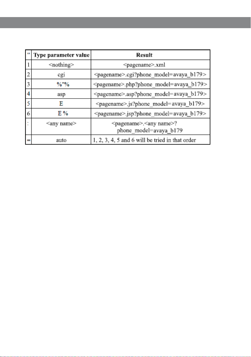
Avaya B179 SIP Conference Phone Installation and Administration Guide
Avaya B179 searches for conguration les in the following order:
Firmware binary
Contains the rmware binary that will be downloaded and installed by Avaya B179 if the
metadata le shows that this is a newer version than the present installed. The binary le can
be downloaded from support.avaya.com.
Firmware metadata le
A metadata le in xml format with information of the rmware version in the binary le. The
le is used to check if the binary le should be downloaded to the phone or not.
The name of this le shall be avaya_fw_version.xml. The le shall contain the following elements in xml format.
<rmware_version>
<version>X.X.X </version> Eg. 2.3.9
<lename>xxxx </lename> Eg. AVAYA_B179_v2.3.9.kt
<checksum>XXXX </checksum> MD5 checksum of the rmware binary
</rmware_version>
57

Avaya B179 SIP Conference Phone Installation and Administration Guide
DEVICE MANAGEMENT CONFIGURATION IN AVAYA B179
Select Settings > Provisioning.
Device management
Enable On enables Device management.
Use DHCP option Set to on if you want to use DHCP option for DM server address.
DHCP option Enter the DHCP option used for the DM server address.
242: Avaya specic option (default)
56: DHCP message
60: Class Id
61: Client Id
66: Server-name
67: Bootle-name
58

Avaya B179 SIP Conference Phone Installation and Administration Guide
File server address DM server address if not provided by DHCP option.
HTTPS protocol Default is auto, but can be set to SSLv2 or SSLv3 if open-ssl auto
detection fails.
Check server cert. Enable authentication with certicate.
Certicate Here you can upload a certicate to the Avaya B179 to be used for
authentication when using Device management.
Root certicate The public key in the root certicate is used to verify other certicates
when using Device management.
Private key Here you can upload a private key to the Avaya B179 to be used for
authentication when using Device management.
Setting up a Device management server
This is a description of a manual method to create the conguration les.
Select Settings > Provisioning.
Enable Device management and enter the server information.
Creating a global conguration le
Congure one phone with the basic conguration.
Click on Export to create a conguratuion le.
If necessary, edit the xml le in a suitable editor.
Some parameters can’t be entered via the web interface (update frequency, pagename,
and letype).
To avoid confusion, it may be wise to delete the local information from the le (eg. ac-
count information).
Save the le with the name a vay ab179. xml on the File server address specied above.
Creating local conguration les
Save a copy of the conguration le for each conference phone on your location with
content only in the elements that shall be unique for each conference phone (eg. account
information).
The default name for each le is avaya-<MAC>.xml, where <MAC> is the MAC address of
the specic conference phone.
Place the conguration les on the File server address specied above.
59

Avaya B179 SIP Conference Phone Installation and Administration Guide
Firmware binary
Place the rmware binary le on the Provisioning server.
Create a Firmware metadata le according to page 49 and place it on the File server
address specied above.
Depending on the server used, and the security settings, there might be necessary to
add the le type .kt to the MIME settings on the server. This is easily checked by trying to
download the kt le from a web browser.
FALL BACK SERVER SUPPORT
Avaya B179 registers concurrently with the primary and secondary proxy servers. The phone
also supports provisioning of a third-party fall back server when a connection with the
primary or secondary server cannot be established. You can congure the third-party server
details by using the web interface and the conguration le.
UPGRADING IN IP OFFICE
Avaya B179 supports the IP Oce check-sync message with le ID 4 for rmware upgrades.
Please see the IP Oce documentation for more information.
HOW TO DO A DOWNGRADE
The only way to “downgrade” – install a previous version of the rmware – is to restore the
rmware to factory default and then install the preferred rmware.
60

Avaya B179 SIP Conference Phone Installation and Administration Guide
IMPORTING AND EXPORTING CONTACTS
You can import contacts from a comma separated values (CSV) le.
The maximum number of contacts allowed in the B179 phone book is 1000. During
importing, the existing contacts are retained.
Importing contacts
Select Phone Book.
Click the Scroll button under the heading Import in the web window.
Open your CSV le.
Click on Import.
The name is limited to 15 characters, since the Avaya B179 screen cannot display more
than 15 characters.
You can export contact books stored in your PC in CSV format.
The way the number can be written may depend on the SIP PBX being used, but you can
use:
Complete phone number, including country code
Phone number, including area code
Local phone number only
Internal speed dial number (with company’s own PBX)
URI, e.g. sip:user@company.com
URI with IP address, e.g. si p:10.10.1.100 (within a local network)
Exporting contacts
You can export your contacts as a CSV document in order to import them into another phone.
Click on Export.
Save the document.
61

Avaya B179 SIP Conference Phone Installation and Administration Guide
IMPORTING AND EXPORTING CONFERENCE GROUPS
The conference group feature requires that your system allows multiple call appearances.
Avaya Aura Communication Manager supports this while Avaya IP Oce and Communication
Server 1000 do not.
The conference groups can be imported and exported in the same way as the contacts in the
phone book, but use a three column csv instead of a two column csv.
The maximum number of conference groups allowed in the B179 phone book is 20.
During importing, the existing conference groups are retained.
The Conference group feature requires that your system allows multiple call
appearances. Avaya Aura Communication Manager supports this while Avaya IP Oce
and Communication Server 1000 do not.
The conference groups can be imported and exported in the same way as the contacts in the
phone book, but use a three column csv instead of a two column csv.
You can import and export up to 20 conf groups
62

Avaya B179 SIP Conference Phone Installation and Administration Guide
COMMUNICATION SERVER 1000 BASED CONFERENCE
You can congure the B179 Conference Phone to use a Avaya Communication Server 1000
(CS1000) for conference calls. A user can press the Conference button on the phone to invoke
the CS1000 server for the conference call.
To use the CS1000 server for conference calls:
Open the conguration le in edit mode.
In the <sip> tag, add the server IP address in the <conference_server> tag.
In the web interface, go to Settings > SIP.
Under Advanced, type the address of the server in the Conference Server eld.
For information about conguring CS1000 server, see Appendix B: Conguring CS1000
Server for B179.
63

Avaya B179 SIP Conference Phone Installation and Administration Guide
TECHNICAL DATA
Size Diameter 240 mm, height 77 mm
Weight 1 kg
Color Liquorice black
Display screen Illuminated graphics (LCD), 128x64
Keypad Alphanumerical 0–9, *, on, o, mute, hold, volume up, volume
down, 5 buttons for menu navigation, line mode, conference
guide
Anti-theft protection Kensington security slot
Memory Support for SD and SDHC memory cards
(Recording capacity 35h/GB)
Connectivity
Network connection Modular 8P8C (RJ45), Ethernet 10/100 Base T
Power supply AC adapter 100–240 V AC/14 V DC
IEEE 802.3af Power over Ethernet, Class III.
Extra microphones 2 modular 4P4C
Auxiliary Modular 4P4C for wireless headset
Network and communication
Network addressing DHCP and static IP
NAT traversal STUN, ICE and TURN
Connection protocol SIP 2.0 (RFC 3261 and companion RFCs)
Transport UDP, TCP, TLS and SIPS
Security SRTP and TLS
Quality of Service DiServ, VLAN and 802.1x
Audio support Codecs: G722, G711 A-law, G711 µ-law, G729ab
DTMF tone generation RFC, SIP INFO, In-band
Time servers NTP and SNTP
Daylight saving: Congurable for automatic adjustments.
Conguration Via integrated web server
Conguration and provisioning
Conguration Via integrated web server, HTTP or HTTPS
Separate user and administrator login for secure conguration.
Device management Support for device management for easy conguration and
updating of multiple conference phones.
64

Avaya B179 SIP Conference Phone Installation and Administration Guide
Directory
Internal phone book 1,000 entries per prole
(4 password protected proles)
Export/import of directory
Call list
External directory Support for LDAP
Sound
Technology OmniSound® Wideband
Microphone Omni-directional
2
Reception area Up to 30 metres
Speaker Frequency band 200–7000 Hz,
Volume 90 dB SPL 0.5 m
Equalizer Three pitches: soft, neutral, bright
, >10 people
Environment
Temperature: 5°–40°C
Relative humidity: 20-80% condensation free
Recommended acoustic conditions:
Reverberation period: 0.5 S Rt 60
Background noise: 45 dBA
Approvals
Electrical safety EN 60950-1:2006,
ANSI/UL 60950-1-2002,
CAN/CSA-C22.2, No. 60950-1-03
EMC/Radio EN 301 489-3 V1.4.1 (2002-08),
EN 301 489-1 V1.6.1 (2005-09),
FCC Part 15 subpart B class A,
FCC Part 15 subpart C,
EN 300220-1:2000,
EN 300220-2:2000
RoHS
65

Avaya B179 SIP Conference Phone Installation and Administration Guide
APPENDIX A: REGISTERING B179 CONFERENCE PHONES
To register a B179 Conference Phone to the Avaya network, you must create a communication
prole for the phone. The communication prole contains a Avaya Aura Communication Manager
endpoint prole and a Avaya Aura Session Manager prole.
The Communication Manager endpoint prole associates the user with a station on a
Communication Manager.
The Session Manager prole creates a unique user identity and assigns the primary and the secondary Session Manager, relevant application sequences, and the survivability server.
CONFIGURING THE SESSION MANAGER PROFILE
Procedure
On the System Manager web console, under Users, click User Management > Manage Users. A list
of users is displayed.
On the User Management page, Click New to create a new endpoint.
Congure the Identity tab.
66

Avaya B179 SIP Conference Phone Installation and Administration Guide
Congure the Communication Prole tab.
When you add a user in Session Manager, System Manag er automatically creates a station in Communication
Man ager.
67

Avaya B179 SIP Conference Phone Installation and Administration Guide
CONFIGURING THE COMMUNICATION MANAGER PROFILE
About this task
To use the conference feature of the B179 Conference Phone, the phone must have atleast
4 call appearances. To assign the call appearances to the B179 phone, congure the station
associated with the Communication Manager endpoint prole of the phone.
When you add a user in Session Manager, System Manager automatically creates a station
in Communication Manager. Use the System Administration Terminal (SAT) interface in
Communication Manager to assign 4 call appearances to each B179 station.
Before you begin
Obtain the user credentials for Communication Manager.
Obtain the station ID of the B179 phone.
Procedure
Log in to the Communication Manager.
To open the SAT interface, type sat.
At the command: prompt, type change station <station ID>.
Under BUTTON ASSIGNMENTS, assign 4 call appearnces to the phone.
68

Avaya B179 SIP Conference Phone Installation and Administration Guide
Upgrade log
Logs the upgrade procedure.
Next Steps
On the phone, check that the square icon next to the extension number is solid.
An empty square indicates that the phone is not registered.
69

Avaya B179 SIP Conference Phone Installation and Administration Guide
APPENDIX B: CONFIGURING CS1000 SERVER FOR B179
Before you begin
Install and congure the CS1000 call server, signaling server, and nodes.
Obtain the administration credentials of the CS1000 call server.
About this task
Using CS1000 Element Manager, congure the following components of the CS1000 Server:
• SIP Line service
• SIP Line D- Channel
• Application Module Link (AML)
• Value Added Server (VAS)
• Zone for SIP phones
• SIP Line Route Data Block (RDB)
• SIP Line Virtual Trunk
• Media Gateway Controller
• SIP Line telephone corresponding to the B179 SIP Conference Phone
Procedure
1. Open Element Manager.
a. Log in to the web UI of Avaya Unied Communications Management (UCM) web interface by using
the IP address of the CS1000 call server. The UCM page is displayed.
70

Avaya B179 SIP Conference Phone Installation and Administration Guide
b. Click the Element Name corresponding to the Element Type CS1000. The System Overview page
is displayed.
71

Avaya B179 SIP Conference Phone Installation and Administration Guide
2. Enable SIP Line Service
a. In the left pane of the System Overview page, click Customers.
b. On the Customers page, click the Customer Number link.
c. On the Customer Details page, click SIP Line Service.
72

Avaya B179 SIP Conference Phone Installation and Administration Guide
d. Check the SIP Line Service checkbox, enter an appropriate User Agent DN prex, and click Save.
3. Enable SIP Line Service on Telephony Node.
a. On the Element Manager page, go to System > IP Network > Nodes: Servers, Media Cards.
Note the IP address of the node, as it will be used in conguring the B179 later. Select the
Node ID on which SIP Line service is to be enabled.
b. On the Node details page, under Applications, and click SIP Line.
c. On the SIP Line Conguration Details page, select Enable gateway service on this node, and
click Save.
73

Avaya B179 SIP Conference Phone Installation and Administration Guide
d. On the Node Details page, click Voice Gateway (VGW) and Codecs, and select the required
codecs.
For G.722 and G.729 support, select Enabled next to Codec G.722 and Codec G.729.
For G.729 Annex B (silence suppression), select Voice Activity Detection (VAD). Ensure that the VAD
setting on Element Manager is consistent with the VAD setting in the B179 phone.
e. Click Save to complete the node conguration. The Node Saved page is displayed.
f. On the Node Saved page, click Transfer Now.
74

Avaya B179 SIP Conference Phone Installation and Administration Guide
After the transfer is complete, the Synchronize Conguration Files (Node ID <ID>) page is displayed.
g. Select the CS1000 call server and click Start Sync. The screen automatically refreshes till the
synchronization is complete. After synchronization is complete, the status of the Synchronization
Status eld changes from Sync required to
Synchronized.
h. To use the new SIP Gateway settings, click Restart Applications.
4. Congure SIP Line D-Channel
a. On the Element Manager page, click Routes and Trunks > D-Channels.
b. Choose a D-Channel number from the list, and select DCH as type.
c. Click to Add.
d. In the D-Channels Property Conguration page, select DCIP as the D-Channel Type, Meridian
Meridian1(SL1) as the Interface type for D-channel, and a Designator. The remaining parameters
can have default values.
75

Avaya B179 SIP Conference Phone Installation and Administration Guide
e. Click to expand the Basic options (BSCOPT) link.
f. Click the Edit button to congure Remote Capabilities.
g. On the Remote Capabilities page, select Message waiting interworking with DMS-100 (MWI) and
Network name display method 2 (ND2).
76

Avaya B179 SIP Conference Phone Installation and Administration Guide
h. Click Return-Remote Capabilities.
i. On the D-Channel Property Conguration page, click Submit.
5. Congure Application Module Link
a. On the Element Manager page, click System > Interfaces > Application Module Link > Add. The
New Application Module Link page is displayed.
b. Enter the AML port number in the Port number text box. The SIP Line Service can use ports 32
through 127.
c. Enter a description, and click Save.
77

Avaya B179 SIP Conference Phone Installation and Administration Guide
6. Congure Value Added Server (VAS)
a. On the Element Manager page, click System > Interfaces > Value Added Server > Add.
b. On the Add Value Added Server page, click Ethernet LAN Link.
c. On the Ethernet LAN Link page, enter a Value added server ID. For example, 064.
d. Select the AML number for Ethernet LAN Link.
e. Ensure that the Application Security check-box is not selected, and click Save.
7. Congure Zone for SIP Phones
a. On the Element Manager page, click System > IP Network > Zones.
b. On the Zones page, click Bandwidth Zones.
c. On the Zone Basic Property and Bandwidth Management page, enter the Zone Number (ZONE)
and description. The remaining parameters can have default values.
d. Click Save.
78

Avaya B179 SIP Conference Phone Installation and Administration Guide
8. Congure SIP Line Route Data Block (RDB)
a. On the Element Manager page, click Routes and Trunks > Routes and Trunks.
b. Click the Add route button for the customer number.
c. On the Basic Conguration page, enter the values for the following parameters:
Route num ber (ROUT): Sel ect a route numbe r
Designa tor eld for trunk (D ES): Enter an approp riate name
Trunk type ( TKTP): Sele ct TIE trunk data b lock (TIE)
Incoming a nd outgoing trun k (ICOG): Select In coming and Outgoi ng
(IAO)
Access code f or the trunk route (ACOD): E nter the access code
The route i s for a virtual tru nk route (VTR K): Select th e check-box
Zone for co dec selectio n and bandwidth: E nter a zone (ZONE)
Node ID of s ignaling serve r of this route (NODE ) Enter the node ID of th e SIP Line Gateway
Protocol I D for the route (PCID): S elect SIP Line (SIPL )
Integrated services digital network option (ISDN): Select the check-box
Mode of op eration (MODE)
Selec t Route uses ISDN Sig naling
Link (ISLD)
D channel n umber (DCH) Enter the D -channel nu mber
Interf ace type for rou te (IFC) Select M eridian M1 (SL1)
Netwo rk calling name all owed (NCNA) Check th e box
Netwo rk call redirec tion (NCRD) Check th e box
79

Avaya B179 SIP Conference Phone Installation and Administration Guide
9. Congure SIP Line Virtual Trunk
a. On the Element Manager page, click Routes and Trunks > Routes and Trunks.
b. To add new trunk members to the new SIP line route, click Add trunk.
c. On the Trunk Property conguration page, set the following parameters to the values specied.
The remaining parameters can have default values.
d. Click Save.
80

Avaya B179 SIP Conference Phone Installation and Administration Guide
10. Congure Media Gateway Controller
a. On the Element Manager page, click IP Network > Media Gateways.
b. In the IPMG column, click the option that supports the digital and analog phones in the communication system.
c. On the IPMG Property Conguration page, click Next.
d. Click to expand the VGW and IP phone codec prole section.
e. Select to expand the Codec G729A option.
81

Avaya B179 SIP Conference Phone Installation and Administration Guide
f. For G.729 Annex B (silence suppression), select Voice Activity Detection (VAD). Ensure that the
VAD setting on Element Manager is consistent with the VAD setting in the B179 phone.
g. Click Save.
h. On the Media Gateway page, select the congured IPMG and click Reboot.
11. Congure SIP Line Telephone
a. On the Element Manager page, click Phones.
b. On the Search for Phones page, click Add.
82

Avaya B179 SIP Conference Phone Installation and Administration Guide
c. On the New Phones page, select the Customer.
d. Select the Phone Type radio button, and from the list of options, select UEXT-SIPL – Universal
Extension SIPL.
e. Click Preview.
83

Avaya B179 SIP Conference Phone Installation and Administration Guide
APPENDIX C: USING CERTIFICATES
Follow these steps to authenticate the Avaya B179 SIP Conference Phones using TLS/SIPS and
EAP-TLS:
Download the root certicate from the Certicate Server.
Create the server certicate from the Certicate Server.
Generate the private key.
Convert the certicates and private key to .PEM format.
Import the .PEM les to the B179 Phone.
For information about using EJBCA certicates on Avaya Aura® System Manager, see the
Administering Avaya Aura® System Manager document.
Procedure
1. Download the root certicate
In the Microsoft Server Certication Authority page, click Download a CA certicate, certicate
chain, or CRL.
To download the root certicate for Avaya B179, click Download CA certicate.
84

Avaya B179 SIP Conference Phone Installation and Administration Guide
2. Get the server certicate
a. On the Microsoft Server Certication Authority page, click Request a certicate.
b. On the Request a certicate page, click advanced certicate request.
c. Enter the information required to create the certicate, and click Submit.
85

Avaya B179 SIP Conference Phone Installation and Administration Guide
d. The certicate is saved to the location specied while setting up the CA.
3. Install the certicate
a. Import the certicate to the web browser.
4. Export private key
a. Go to Internet Options > Content > Certicates, select the certicate you installed, and click
Export.
b. Select Yes, export the private key, and click Next.
c. Select the format in which you want to export the certicate le, and click Next.
d. Specify the le name and browse to the location to where the certicate must be exported.
6. Convert the certicates to .PEM format
The B179 phone supports certicates in the .PEM format only. You must convert the certicates
and private keys to .PEM before using in the B179 phones.
a. Use the following Openssl commands to convert the les:
From .DER to .PEM
openssl x509 -inform der -in certicate.cer -out certicate.pem
From .PFX to .PEM
openssl pkcs12 -in certicate.pfx -out certicate.cer -nodes
Next steps
Browse to the .PEM les from the B179 web UI to use EAP TLS mode of authentication.
86
 Loading...