

Avaya Aura S8800 Maintaining

Maintaining the Avaya S8800 Server for
Avaya Aura® SIP Enablement Services
03-603448
November 2009
Issue 1

©
2011 Avaya Inc.
All Rights Reserved.
Notices
While reasonable efforts have been made to ensure that the
information in this document is complete and accurate at the time of
printing, Avaya assumes no liability for any errors. Avaya reserves the
right to make changes and corrections to the information in this
document without the obligation to notify any person or organization of
such changes.
For full support, please see the complete document, Avaya Support
Notices for Hardware Documentation, document number 03–600759.
To locate this document on our Web site, simply go to
www.avaya.com/support and search for the document number in the
search box.
Documentation disclaimer
“Documentation” means information published by Avaya in varying
mediums which may include product information, operating instructions
and performance specifications that Avaya generally makes available
to users of its products. Documentation does not include marketing
materials. Avaya shall not be responsible for any modifications,
additions, or deletions to the original published version of
documentation unless such modifications, additions, or deletions were
performed by Avaya. End User agrees to indemnify and hold harmless
Avaya, Avaya's agents, servants and employees against all claims,
lawsuits, demands and judgments arising out of, or in connection with,
subsequent modifications, additions or deletions to this documentation,
to the extent made by End User.
Link disclaimer
Avaya is not responsible for the contents or reliability of any linked Web
sites referenced within this site or documentation provided by Avaya.
Avaya is not responsible for the accuracy of any information, statement
or content provided on these sites and does not necessarily endorse
the products, services, or information described or offered within them.
Avaya does not guarantee that these links will work all the time and has
no control over the availability of the linked pages.
Warranty
Avaya provides a limited warranty on its Hardware and Software
(“Product(s)”). Refer to your sales agreement to establish the terms of
the limited warranty. In addition, Avaya’s standard warranty language,
as well as information regarding support for this Product while under
warranty is available to Avaya customers and other parties through the
Avaya Support Web site:
you acquired the Product(s) from an authorized Avaya reseller outside
of the United States and Canada, the warranty is provided to you by
said Avaya reseller and not by Avaya.
Copyright
Except where expressly stated otherwise, no use should be made of
materials on this site, the Documentation, Software, or Hardware
provided by Avaya. All content on this site, the documentation and the
Product provided by Avaya including the selection, arrangement and
design of the content is owned either by Avaya or its licensors and is
protected by copyright and other intellectual property laws including the
sui generis rights relating to the protection of databases. You may not
modify, copy, reproduce, republish, upload, post, transmit or distribute
in any way any content, in whole or in part, including any code and
software unless expressly authorized by Avaya. Unauthorized
reproduction, transmission, dissemination, storage, and or use without
the express written consent of Avaya can be a criminal, as well as a
civil offense under the applicable law.
Contact Avaya Support
Avaya provides a telephone number for you to use to report problems
or to ask questions about your Product. The support telephone number
http://support.avaya.com. Please note that if
http://
is 1-800-242-2121 in the United States. For additional support
telephone numbers, see the Avaya W eb site:
http://support.avaya.com.
2 Maintaining the Avaya S8800 Server for Avaya Aura® SIP Enablement Services November 2009
Comments? infodev@avaya.com

Contents
Chapter 1: Introduction......................................................................................................
Maintain the Avaya S8800 Server.............................................................................................................
Chapter 2: Replace Avaya SES S8800 Server..................................................................
Maintenance Procedures..........................................................................................................................
Reuse of hardware components in replacement servers..........................................................................
Required equipment and tools..................................................................................................................
Tasks to replace an Avaya S8800 Server.................................................................................................
Removing the server from the rack...........................................................................................................
Installing the server in the rack.................................................................................................................
Connection schema for simplex server.....................................................................................................
Connection schema for cable duplicated servers.....................................................................................
Connection schema for network duplicated servers.................................................................................
Chapter 3: Replace FRUs...................................................................................................
Removing and installing the server cover.................................................................................................
Removing the server cover..............................................................................................................
Installing the server cover................................................................................................................
Replacing memory modules......................................................................................................................
Sequence for populating DIMM connectors.....................................................................................
Removing the DIMM air baffle..........................................................................................................
Removing a memory module...........................................................................................................
Installing a memory module.............................................................................................................
Installing the DIMM air baffle............................................................................................................
Replacing a hard disk drive.......................................................................................................................
Removing a hard disk drive..............................................................................................................
Installing a hard disk drive................................................................................................................
Removing and installing a PCI riser-card assembly.................................................................................
Removing a PCI riser-card assembly...............................................................................................
Installing a PCI riser-card assembly.................................................................................................
Replacing a power supply.........................................................................................................................
Removing a power supply................................................................................................................
Installing a power supply..................................................................................................................
Replacing the RAID battery.......................................................................................................................
Removing the RAID battery..............................................................................................................
Installing the RAID battery................................................................................................................
Chapter 4: Diagnostics LEDs.............................................................................................
Light path diagnostics...............................................................................................................................
About light path diagnostics.............................................................................................................
Using light path diagnostics to identify system errors......................................................................
Operator information panel...............................................................................................................
Accessing the light path diagnostics panel.......................................................................................
Light path diagnostics panel.............................................................................................................
Troubleshooting light path diagnostic LEDs.....................................................................................
System board LEDs.........................................................................................................................
Power supply LEDs...................................................................................................................................
5
5
7
7
7
7
8
9
9
11
12
12
15
15
15
16
17
17
19
20
22
23
25
25
26
27
27
29
31
31
32
34
34
35
37
37
37
37
38
40
41
42
49
51
Maintaining the Avaya S8800 Server for Avaya Aura® SIP Enablement Services November 2009 3

Power supply LEDs..........................................................................................................................
Identifying power supply problems...................................................................................................
Chapter 5: Troubleshooting...............................................................................................
Troubleshooting power supply problems..................................................................................................
Server has no AC power..................................................................................................................
Error LED is lit for one power supply................................................................................................
Power supply AC LED is lit...............................................................................................................
Faulty power supply.........................................................................................................................
Troubleshooting power problems..............................................................................................................
Power control button does not work.................................................................................................
Server does not start........................................................................................................................
Server does not turn off....................................................................................................................
Troubleshooting hard disk drives..............................................................................................................
Failed hard disk drive.......................................................................................................................
A newly installed hard disk drive is not recognized..........................................................................
Multiple hard disk drives fail.............................................................................................................
Multiple hard disk drives are offline..................................................................................................
A replacement hard disk drive does not rebuild...............................................................................
Troubleshooting light path diagnostic LEDs..............................................................................................
OVERSPEC LED is lit......................................................................................................................
LOG LED is lit...................................................................................................................................
LINK LED is lit..................................................................................................................................
PS LED is lit.....................................................................................................................................
PCI LED is lit....................................................................................................................................
SP LED is lit.....................................................................................................................................
FAN LED is lit...................................................................................................................................
TEMP LED is lit................................................................................................................................
MEM LED is lit..................................................................................................................................
NMI LED is lit....................................................................................................................................
CNFG LED is lit................................................................................................................................
CPU LED is lit...................................................................................................................................
VRM LED is lit..................................................................................................................................
DASD LED is lit................................................................................................................................
RAID LED is lit..................................................................................................................................
BRD LED is lit...................................................................................................................................
Index.....................................................................................................................................
51
51
53
53
53
53
54
55
55
55
57
57
58
58
59
59
60
60
61
61
62
62
62
63
64
64
64
65
66
67
67
68
68
69
69
71
4 Maintaining the Avaya S8800 Server for Avaya Aura® SIP Enablement Services November 2009

Chapter 1: Introduction
Maintain the Avaya S8800 Server
This document describes the maintenance procedures of S8800 Server running SIP
Enablement Services with simplex, duplex and network duplex configurations. The document
has the following sections:
• Replace Avaya S8800 Server in simplex mode
• Replace Avaya S8800 Server in cable duplex mode
• Replace Avaya S8800 Server in network duplex mode
• Replacing the Field Replaceable Units (FRU)
• Troubleshooting the Avaya S8800 Server
For Installing software procedures of SES, see Installing, Administering, Maintaining, and
Troubleshooting Avaya Aura™ SIP Enablement Services (03-600768).
Maintaining the Avaya S8800 Server for Avaya Aura® SIP Enablement Services November 2009 5

Introduction
6 Maintaining the Avaya S8800 Server for Avaya Aura® SIP Enablement Services November 2009
Comments? infodev@avaya.com

Chapter 2: Replace Avaya SES S8800
Server
Maintenance Procedures
The maintenance procedures for Avaya S8800 Server in simplex, cable duplicated and
network duplicated configurations are similar.
See connection schema for details:
•
simplex server on page 11
• cable duplicated servers on page 12
• network duplicated servers on page 12
Reuse of hardware components in replacement servers
When you replace the Avaya S8800 Server, you must reuse the following components:
• DIMMs if more than two (4 GB capacity)
• Hard disk drives
You must remove these components from the defective server and install them in the
replacement server.
Required equipment and tools
• Replacement Avaya S8800 Server
• #2 cross-point (Phillips) screwdriver or 3/8 inch flathead screwdriver
• USB keyboard, USB mouse, and monitor
• Electrostatic wrist ground strap and mat
Maintaining the Avaya S8800 Server for Avaya Aura® SIP Enablement Services November 2009 7
Replace Avaya SES S8800 Server
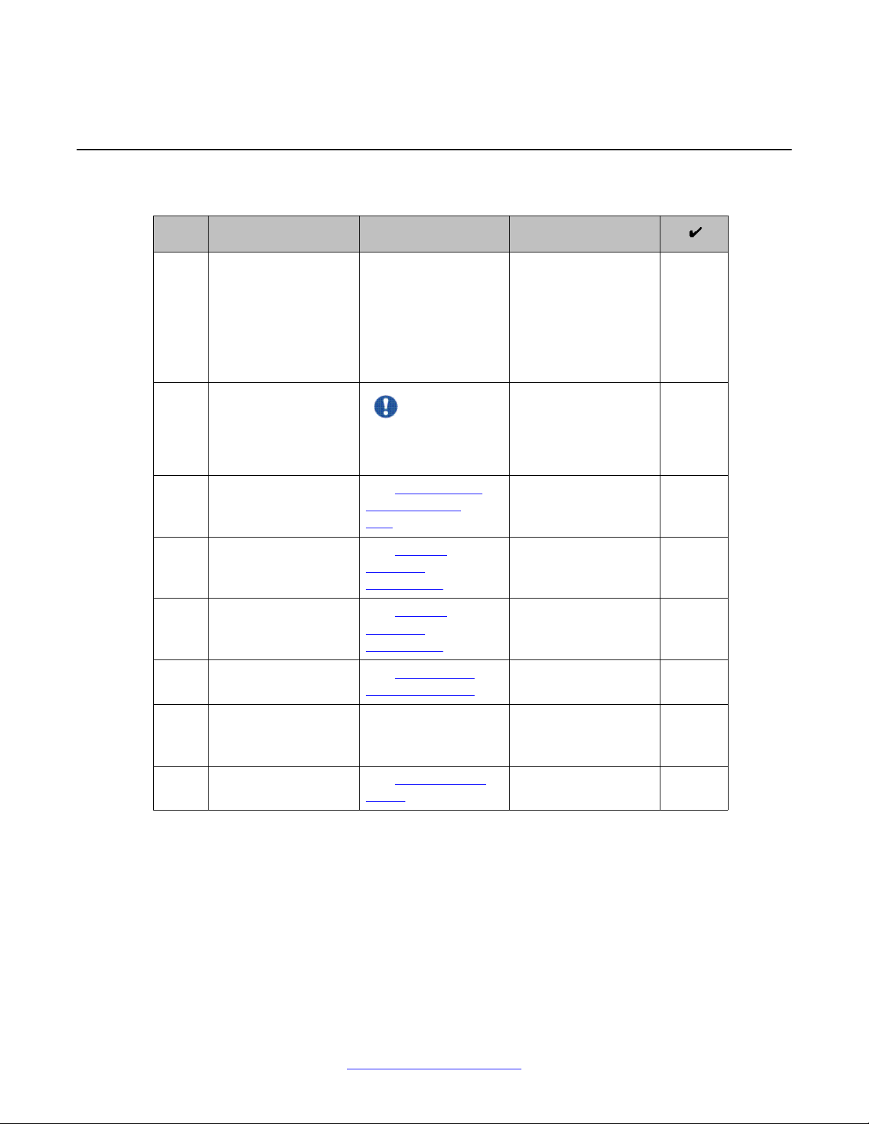
Tasks to replace an Avaya S8800 Server
# Task Description Notes
1 Shut down the server. If you can shut down
the server from the
software, do so.
Otherwise, press the
power button for
several seconds to
shut down the server.
2 Disconnect all power
cords and external
cables.
Important:
Be sure to label the
cables for easy
reconnection.
3 Remove the server
from the rack.
4 Remove the reusable
components from the
failed server.
5 Install the reusable
components in the
new server.
6 Install the new server
in the rack.
7 Reconnect the
external cables and
power cords.
8 Turn on the server. See Turning on the
See Removing the
server from the
rack on page 9.
See Reusing
hardware
components.
See Reusing
hardware
components.
See Installing the
server in the rack.
server.
8 Maintaining the Avaya S8800 Server for Avaya Aura® SIP Enablement Services November 2009
Comments? infodev@avaya.com

Removing the server from the rack
Procedure
1. Turn off the server and all attached devices.
2. Label and disconnect all power cords and external cables.
3. Push the locking levers (1) forward. See the following figure.
Removing the server from the rack
4. Lift up the front of the server (2). See the preceding figure.
5. Pull the server out of the rack (3). See the preceding figure.
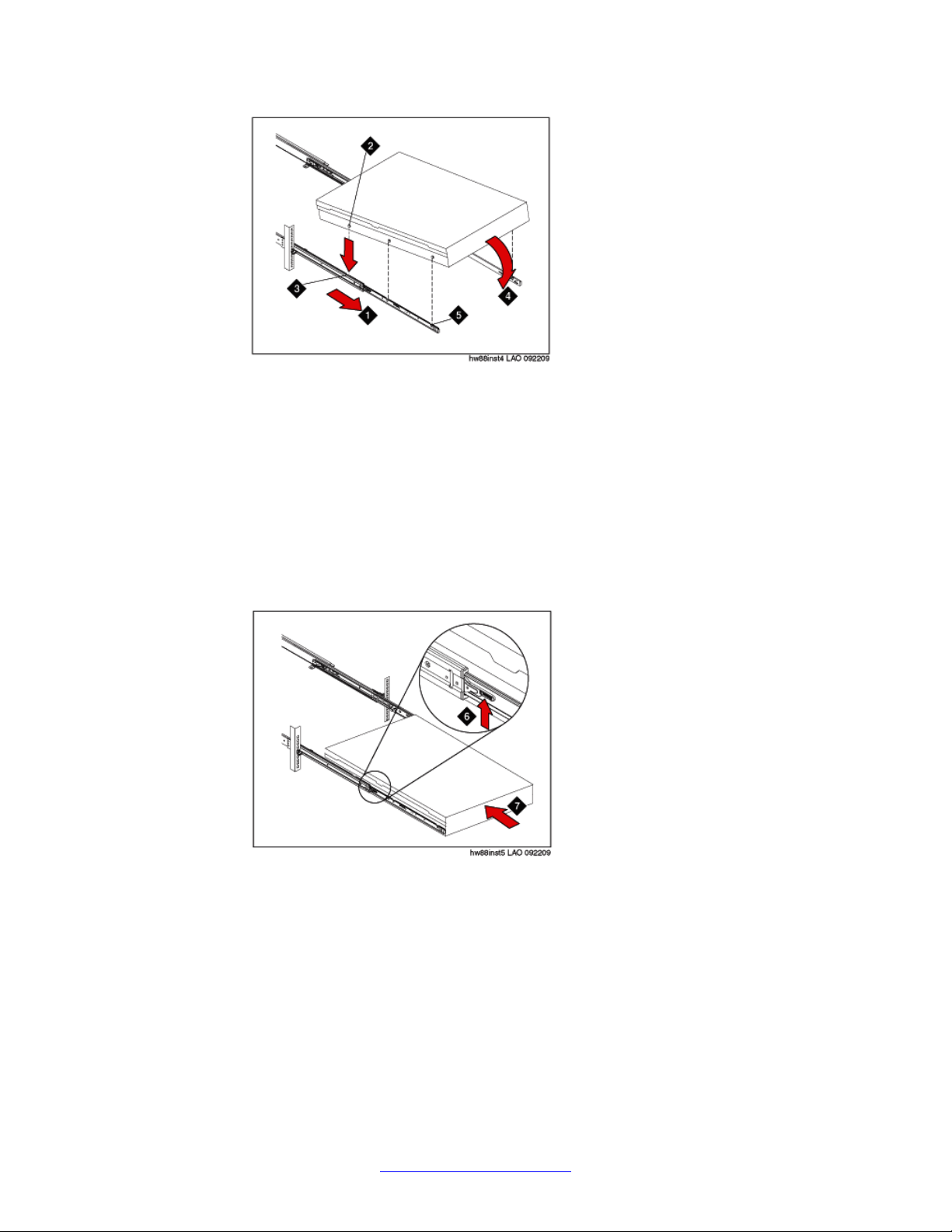
Installing the server in the rack
Procedure
1. Pull the slide rails forward (1) until they click, two times, into place. See the following
figure.
Maintaining the Avaya S8800 Server for Avaya Aura® SIP Enablement Services November 2009 9
Replace Avaya SES S8800 Server
2. Carefully lift the server and tilt it into position over the slide rails so that the rear nail
heads (2) on the server line up with the rear slots (3) on the slide rails. See the
preceding figure.
3. Slide the server down until the rear nail heads slip into the two rear slots.
4. Slowly lower the front of the server (4) until the other nail heads slip into the other
slots on the slide rails. See the preceding figure.
5. Make sure that the front latch (5) slides over the nail heads. See the preceding
figure.
6. Lift the locking levers (6) on the slide rails. See the following figure.
7. Push the server (7) all the way into the rack until it clicks into place. See the
preceding figure.
8. Insert the optional M6 screws (8) in the front of the server when you move the rack
cabinet or if you install the rack cabinet in a vibration-prone area. See the following
figure.
10 Maintaining the Avaya S8800 Server for Avaya Aura® SIP Enablement Services November 2009
Comments? infodev@avaya.com
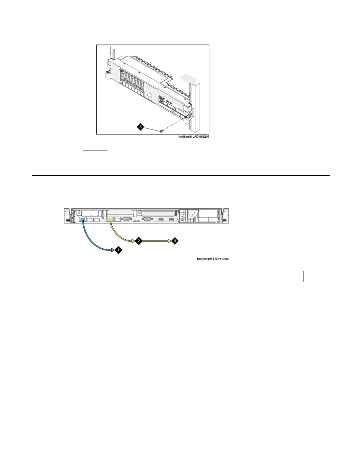
Connection schema for simplex server
Connection schema for simplex server
The following graphic shows the connection schema for a S8800 simplex server
2
Ethernet cable connecting to customer network port (eth0).
Maintaining the Avaya S8800 Server for Avaya Aura® SIP Enablement Services November 2009 11
Replace Avaya SES S8800 Server
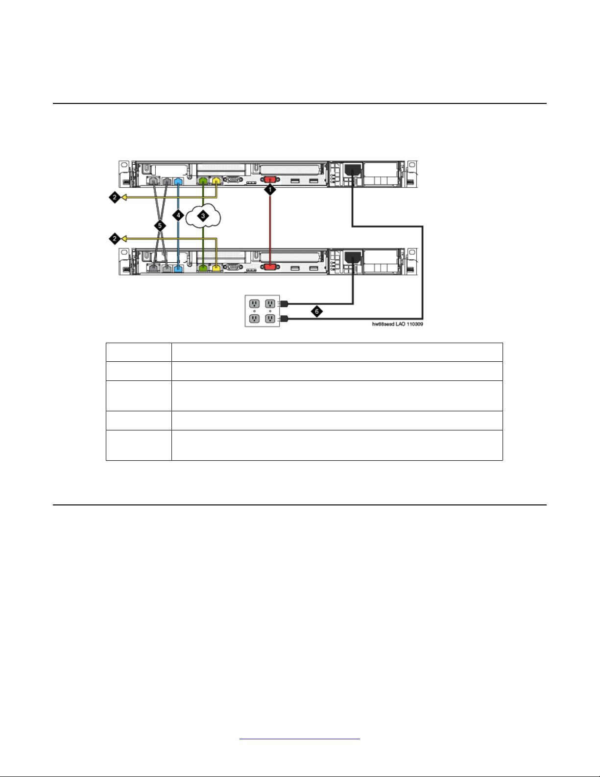
Connection schema for cable duplicated servers
The following graphic show the connection schema for a S8800 cable duplicated server pair.
1 Null modem cable connecting the servers through the RS-232 serial port.
2 Ethernet cable connecting to the services port (Eth1).
3 Ethernet cable connecting the servers to the customer network through the
customer network port (Eth0).
4 Ethernet cable connecting the servers through the dual NIC port (Eth3).
5 The cable connects the IMM port of one server to NIC port 3 (Eth2) of the
other.
Connection schema for network duplicated servers
The following graphics show the connection schema for a S8800 network duplicated server.
12 Maintaining the Avaya S8800 Server for Avaya Aura® SIP Enablement Services November 2009
Comments? infodev@avaya.com
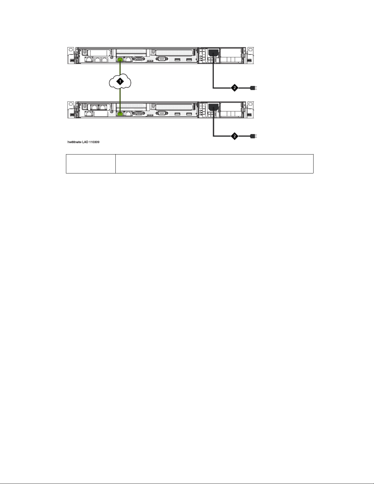
Connection schema for network duplicated servers
1 Straight-through Ethernet cable connecting the servers to the customer
network through the customer network port (Eth0)
Maintaining the Avaya S8800 Server for Avaya Aura® SIP Enablement Services November 2009 13

Replace Avaya SES S8800 Server
14 Maintaining the Avaya S8800 Server for Avaya Aura® SIP Enablement Services November 2009
Comments? infodev@avaya.com
Chapter 3: Replace FRUs
Removing and installing the server cover
Removing the server cover
Before you begin
Before you disconnect the server from the power source, make a note of which LEDs are lit,
including the LEDs that are lit on the operation information panel, on the light path diagnostics
panel, and LEDs inside the server on the system board. Once you disconnect the server from
the power source, you lose the ability to view the LEDs because the LEDs are not lit when the
power source is removed.
About this task
Remove the server cover to access the server's internal components.
Important:
Always use an electrostatic-discharge wrist strap or other grounding system when you work
inside the server. See Protecting against ESD damage for more information.
Procedure
1. If you are planning to view the error LEDs that are on the system board and
components, leave the server connected to power.
2. If you are planning to install or remove a DIMM, PCI card, battery , or other non-hot
swap device:
a. Turn off the server and all attached devices.
b. Label and disconnect all power cords and external cables.
3. If the server has been installed in a rack, slide the server out from the rack
enclosure.
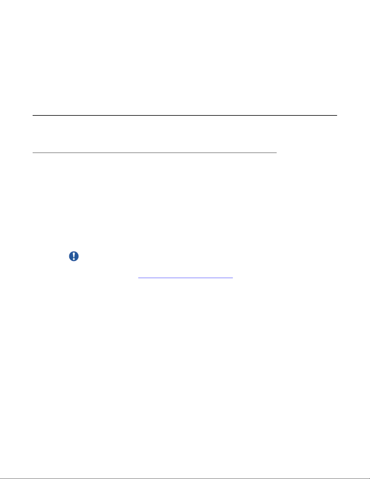
4. Press down firmly on the blue tab on the top (near the front of the server) of the
cover and slide the cover toward the back of the server until the cover has
disengaged from the chassis. See the following figure.
Maintaining the Avaya S8800 Server for Avaya Aura® SIP Enablement Services November 2009 15
Replace FRUs
1 Cover
2 Tab
5. Lift the server cover off the server and set it aside.
Important:
For proper cooling and airflow, replace the cover before you turn on the server.
Operating the server for extended periods of time (over 30 minutes) with the cover
removed might damage server components.
Installing the server cover
About this task
Important:
Always use an electrostatic-discharge wrist strap or other grounding system when you work
inside the server. See Protecting against ESD damage for more information.
Procedure
1. Make sure that all internal cables, PCIe cards, and other components are installed
and seated correctly and that you have not left loose tools or parts inside the server.
Also, make sure that all internal cables are correctly routed.
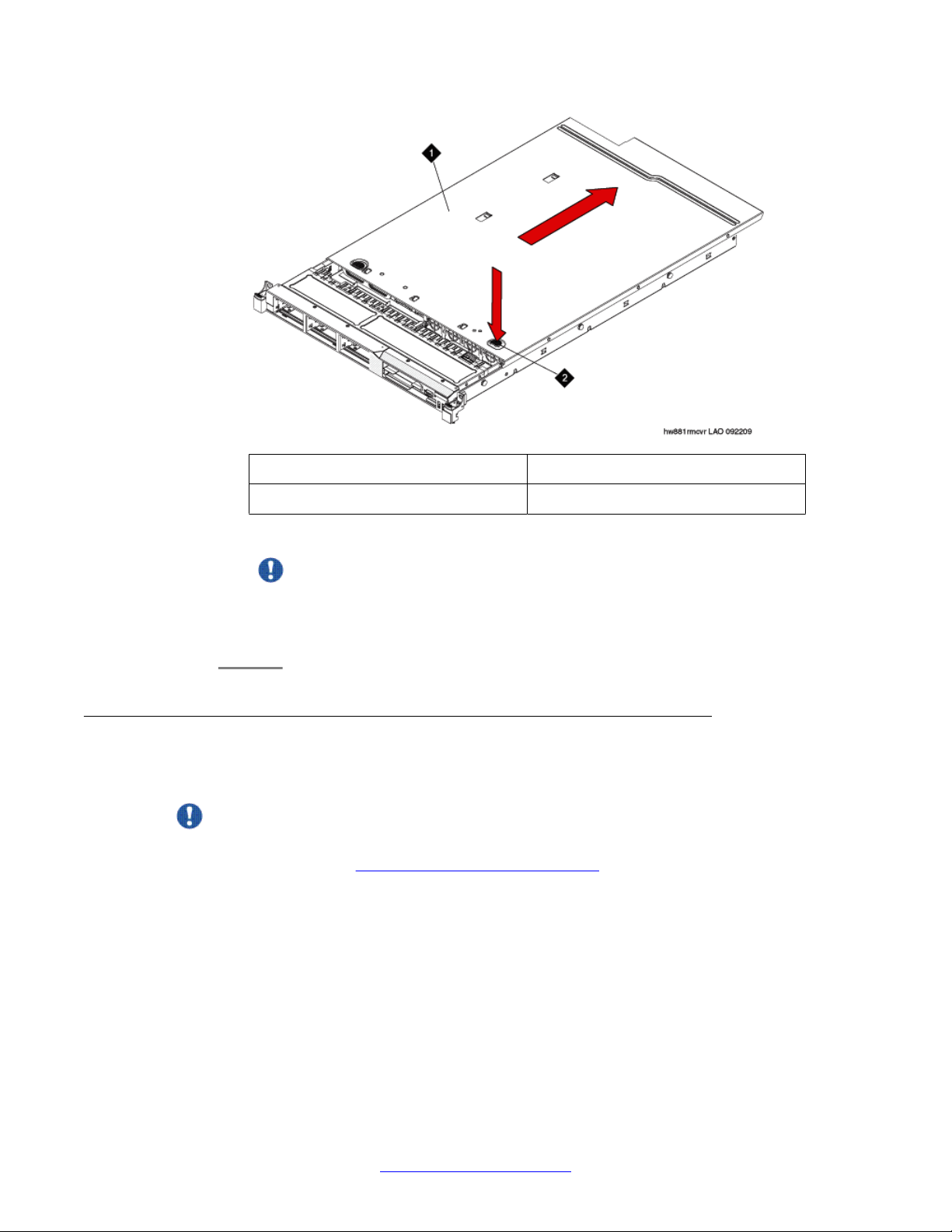
2. Position the cover on top of the server. See the following figure.
16 Maintaining the Avaya S8800 Server for Avaya Aura® SIP Enablement Services November 2009
Comments? infodev@avaya.com
Replacing memory modules
Important:
Before you slide the cover forward, make sure that all the tabs on both the front,
back, and side of the cover engage the chassis correctly. If all the tabs do not
engage the chassis correctly, it will be very difficult to remove the cover later.
1 Cover
2 Tab
3. Slide the cover toward the front of the server.
4. Make sure that the cover correctly engages all the inset tabs on the server.
5. Slide the server all the way into the rack until it latches.
6. Reconnect the external cables and power cords.
Replacing memory modules
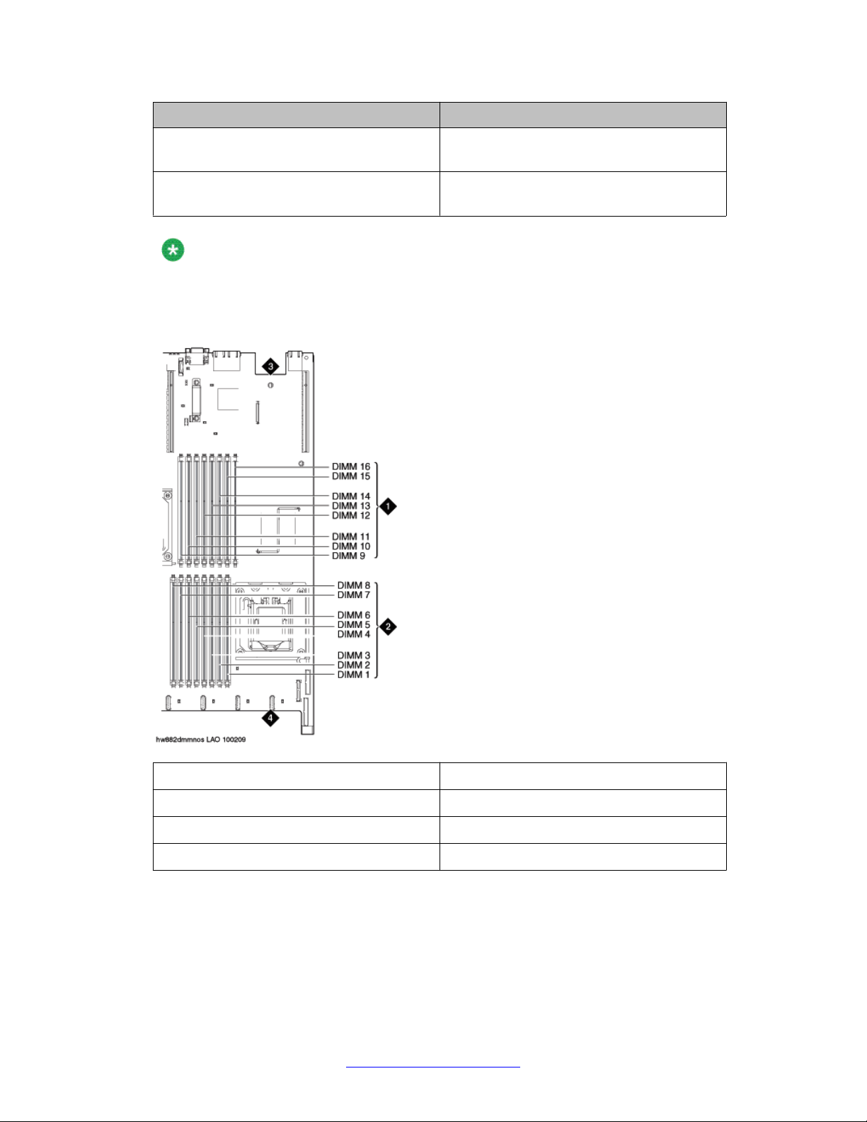
Sequence for populating DIMM connectors
When you install dual in-line memory modules (DIMMs), install them in the sequence shown
in the following table to optimize system performance.
Maintaining the Avaya S8800 Server for Avaya Aura® SIP Enablement Services November 2009 17
Replace FRUs
The following figure shows the numbering sequence of the DIMMs.
Installed microprocessors DIMM connector population sequence
Microprocessor 1 Install the DIMMs in the following sequence:
3, 6, 8, 2, 5, 7, 1, 4
Microprocessor 2 Install the DIMMs in the following sequence:
11, 14, 16, 10, 13, 15, 9, 12
Note:
Dual microprocessors require equal distribution of DIMMs between the processors. For
example, a 12GB DIMM would have connectors 3,6,8 and 11,14,16 populated.
1 DIMMs for microprocessor 2
2 DIMMs for microprocessor 1
3 Back of server
4 Front of server
18 Maintaining the Avaya S8800 Server for Avaya Aura® SIP Enablement Services November 2009
Comments? infodev@avaya.com
Removing the DIMM air baffle
About this task
You must remove the DIMM air baffle to replace or install a memory module.
Caution:
For proper cooling and airflow, replace the air baf fle before you turn on the server . Operating
the server with an air baffle removed might damage server components.
Important:
Always use an electrostatic-discharge wrist strap or other grounding system when you work
inside the server. See Protecting against ESD damage for more information.
Procedure
1. Turn off the server and all attached devices.
Replacing memory modules
2. Label and disconnect all power cords and external cables.
3. Remove the cover.
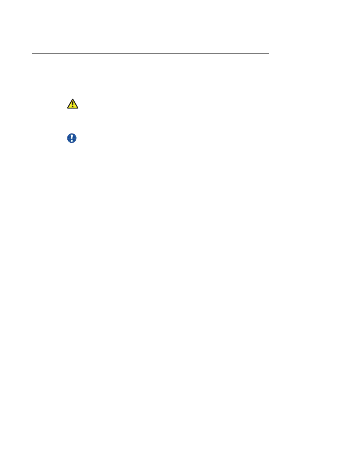
4. Grasp the DIMM air baffle and lift the air baffle out of the server . Make sure that the
pin comes out of the pin hole on the system board to the left of DIMM connector 8.
See the following figure.
Maintaining the Avaya S8800 Server for Avaya Aura® SIP Enablement Services November 2009 19
Replace FRUs
1 Baffle pin
2 Baffle pin hole
3 DIMM air baffle
Related topics:
Removing the server cover on page 15
Removing a memory module
Before you begin
Remove the DIMM air baffle.
About this task
Important:
Always use an electrostatic-discharge wrist strap or other grounding system when you work
inside the server. See Protecting against ESD damage for more information.
20 Maintaining the Avaya S8800 Server for Avaya Aura® SIP Enablement Services November 2009
Comments? infodev@avaya.com
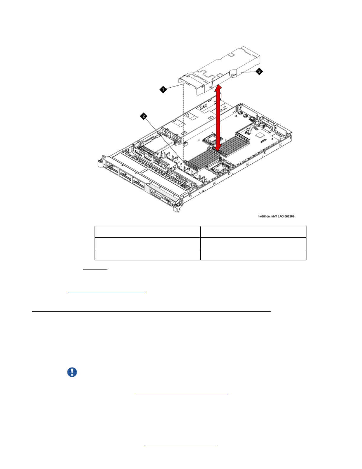
Procedure
Carefully open the retaining clips on each end of the memory module connector and
remove the memory module. See the following figure.
Open and close the clips gently to avoid breaking the retaining clips or damaging
the memory module connectors.
Replacing memory modules
Important:
1 Memory module
2 Retaining clip
When you install or remove memory modules, the server configuration information
changes. When you restart the server, the system displays a message that indicates
that the memory configuration has changed.
Next steps
Install a memory module.
Related topics:
Removing the server cover on page 15
Removing the DIMM air baffle on page 19
Maintaining the Avaya S8800 Server for Avaya Aura® SIP Enablement Services November 2009 21
Replace FRUs
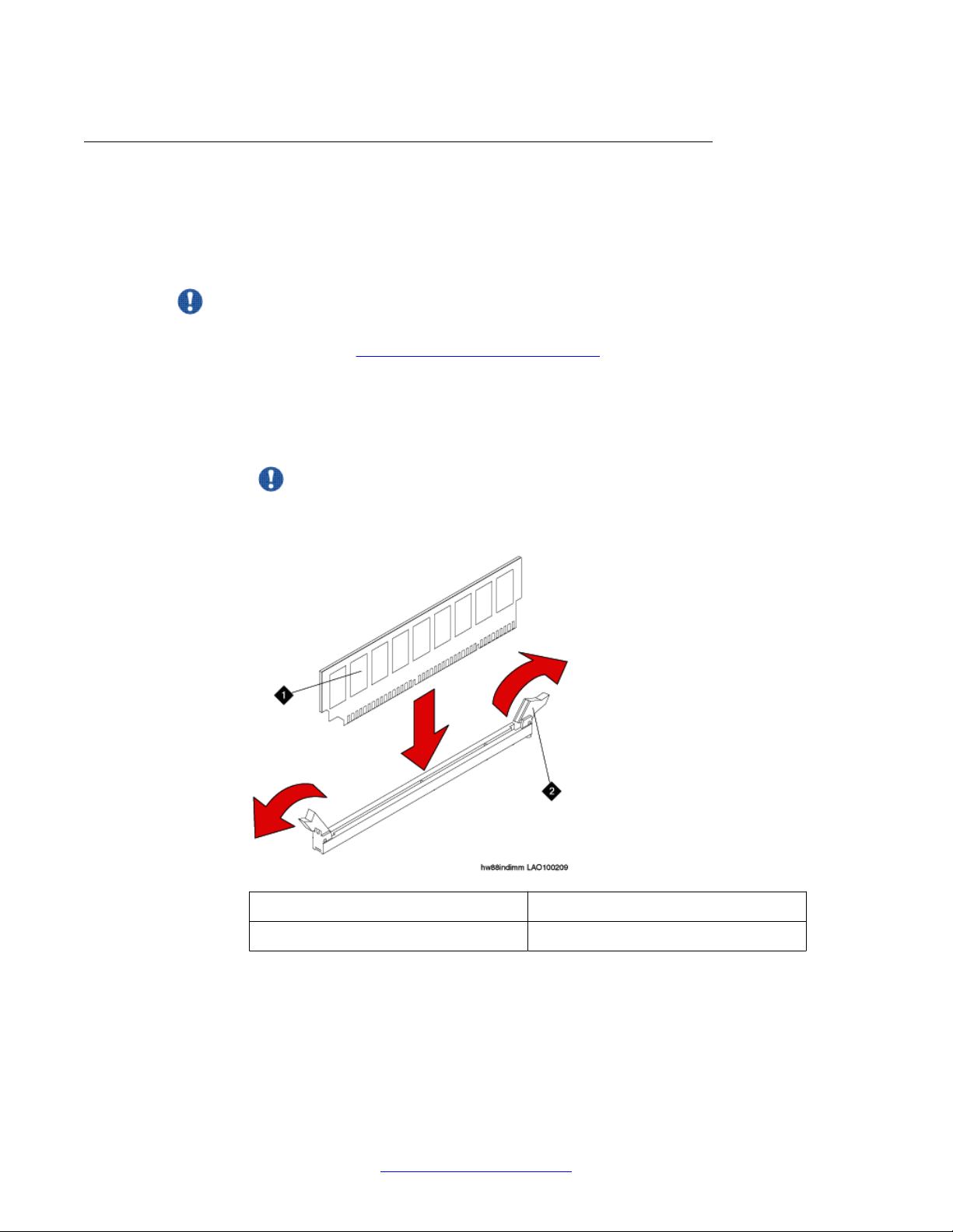
Installing a memory module
Before you begin
Remove the DIMM air baffle.
About this task
Important:
Always use an electrostatic-discharge wrist strap or other grounding system when you work
inside the server. See Protecting against ESD damage for more information.
Procedure
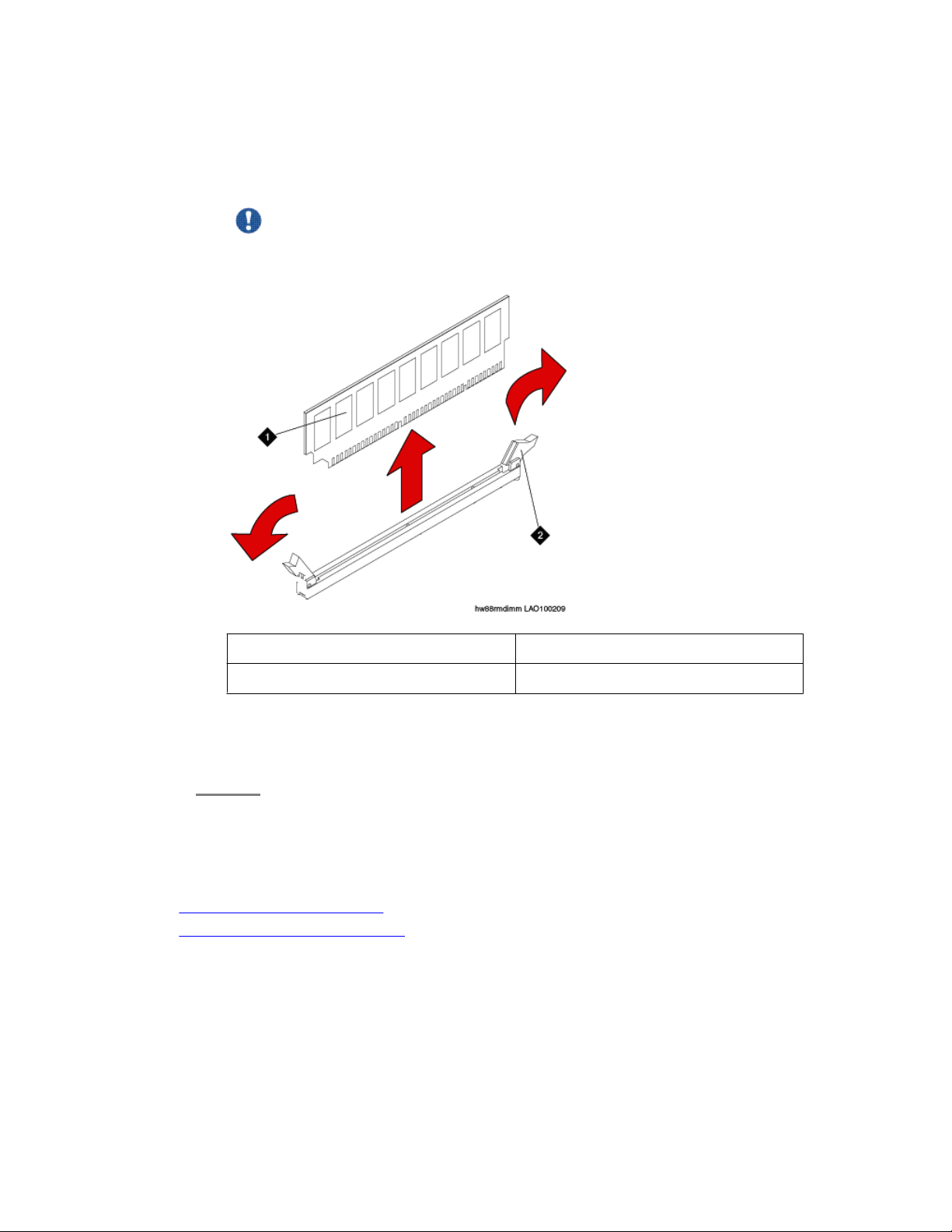
1. Carefully open the retaining clips on each end of the memory module connector.
See the following figure.
Important:
Open and close the clips gently to avoid breaking the retaining clips or damaging
the memory module connectors.
1 Memory module
2 Retaining clip
2. Touch the static-protective package that contains the memory module to any
unpainted metal surface on the server.
3. Remove the memory module from the package.
22 Maintaining the Avaya S8800 Server for Avaya Aura® SIP Enablement Services November 2009
Comments? infodev@avaya.com
 Loading...