

Page 1

Administering Network Connectivity on
Avaya Aura® Communication Manager
Release 7.1.3
Issue 4
February 2020
Page 2

©
2017-2020, Avaya Inc.
All Rights Reserved.
Notice
While reasonable efforts have been made to ensure that the
information in this document is complete and accurate at the time of
printing, Avaya assumes no liability for any errors. Avaya reserves
the right to make changes and corrections to the information in this
document without the obligation to notify any person or organization
of such changes.
Documentation disclaimer
“Documentation” means information published in varying mediums
which may include product information, operating instructions and
performance specifications that are generally made available to users
of products. Documentation does not include marketing materials.
Avaya shall not be responsible for any modifications, additions, or
deletions to the original published version of Documentation unless
such modifications, additions, or deletions were performed by or on
the express behalf of Avaya. End User agrees to indemnify and hold
harmless Avaya, Avaya's agents, servants and employees against all
claims, lawsuits, demands and judgments arising out of, or in
connection with, subsequent modifications, additions or deletions to
this documentation, to the extent made by End User.
Link disclaimer
Avaya is not responsible for the contents or reliability of any linked
websites referenced within this site or Documentation provided by
Avaya. Avaya is not responsible for the accuracy of any information,
statement or content provided on these sites and does not
necessarily endorse the products, services, or information described
or offered within them. Avaya does not guarantee that these links will
work all the time and has no control over the availability of the linked
pages.
Warranty
Avaya provides a limited warranty on Avaya hardware and software.
Refer to your sales agreement to establish the terms of the limited
warranty. In addition, Avaya’s standard warranty language, as well as
information regarding support for this product while under warranty is
available to Avaya customers and other parties through the Avaya
Support website:
https://support.avaya.com/helpcenter/
getGenericDetails?detailId=C20091120112456651010 under the link
“Warranty & Product Lifecycle” or such successor site as designated
by Avaya. Please note that if You acquired the product(s) from an
authorized Avaya Channel Partner outside of the United States and
Canada, the warranty is provided to You by said Avaya Channel
Partner and not by Avaya.
“Hosted Service” means an Avaya hosted service subscription that
You acquire from either Avaya or an authorized Avaya Channel
Partner (as applicable) and which is described further in Hosted SAS
or other service description documentation regarding the applicable
hosted service. If You purchase a Hosted Service subscription, the
foregoing limited warranty may not apply but You may be entitled to
support services in connection with the Hosted Service as described
further in your service description documents for the applicable
Hosted Service. Contact Avaya or Avaya Channel Partner (as
applicable) for more information.
Hosted Service
THE FOLLOWING APPLIES ONLY IF YOU PURCHASE AN AVAYA
HOSTED SERVICE SUBSCRIPTION FROM AVAYA OR AN AVAYA
CHANNEL PARTNER (AS APPLICABLE), THE TERMS OF USE
FOR HOSTED SERVICES ARE AVAILABLE ON THE AVAYA
WEBSITE,
HTTPS://SUPPORT.AVAYA.COM/LICENSEINFO UNDER
THE LINK “Avaya Terms of Use for Hosted Services” OR SUCH
SUCCESSOR SITE AS DESIGNATED BY AVAYA, AND ARE
APPLICABLE TO ANYONE WHO ACCESSES OR USES THE
HOSTED SERVICE. BY ACCESSING OR USING THE HOSTED
SERVICE, OR AUTHORIZING OTHERS TO DO SO, YOU, ON
BEHALF OF YOURSELF AND THE ENTITY FOR WHOM YOU ARE
DOING SO (HEREINAFTER REFERRED TO INTERCHANGEABLY
AS “YOU” AND “END USER”), AGREE TO THE TERMS OF USE. IF
YOU ARE ACCEPTING THE TERMS OF USE ON BEHALF A
COMPANY OR OTHER LEGAL ENTITY, YOU REPRESENT THAT
YOU HAVE THE AUTHORITY TO BIND SUCH ENTITY TO THESE
TERMS OF USE. IF YOU DO NOT HAVE SUCH AUTHORITY, OR IF
YOU DO NOT WISH TO ACCEPT THESE TERMS OF USE, YOU
MUST NOT ACCESS OR USE THE HOSTED SERVICE OR
AUTHORIZE ANYONE TO ACCESS OR USE THE HOSTED
SERVICE.
Licenses
THE SOFTWARE LICENSE TERMS AVAILABLE ON THE AVAYA
WEBSITE,
HTTPS://SUPPORT.AVAYA.COM/LICENSEINFO,
UNDER THE LINK “AVAYA SOFTWARE LICENSE TERMS (Avaya
Products)” OR SUCH SUCCESSOR SITE AS DESIGNATED BY
AVAYA, ARE APPLICABLE TO ANYONE WHO DOWNLOADS,
USES AND/OR INSTALLS AVAYA SOFTWARE, PURCHASED
FROM AVAYA INC., ANY AVAYA AFFILIATE, OR AN AVAYA
CHANNEL PARTNER (AS APPLICABLE) UNDER A COMMERCIAL
AGREEMENT WITH AVAYA OR AN AVAYA CHANNEL PARTNER.
UNLESS OTHERWISE AGREED TO BY AVAYA IN WRITING,
AVAYA DOES NOT EXTEND THIS LICENSE IF THE SOFTWARE
WAS OBTAINED FROM ANYONE OTHER THAN AVAYA, AN AVAYA
AFFILIATE OR AN AVAYA CHANNEL PARTNER; AVAYA
RESERVES THE RIGHT TO TAKE LEGAL ACTION AGAINST YOU
AND ANYONE ELSE USING OR SELLING THE SOFTWARE
WITHOUT A LICENSE. BY INSTALLING, DOWNLOADING OR
USING THE SOFTWARE, OR AUTHORIZING OTHERS TO DO SO,
YOU, ON BEHALF OF YOURSELF AND THE ENTITY FOR WHOM
YOU ARE INSTALLING, DOWNLOADING OR USING THE
SOFTWARE (HEREINAFTER REFERRED TO
INTERCHANGEABLY AS “YOU” AND “END USER”), AGREE TO
THESE TERMS AND CONDITIONS AND CREATE A BINDING
CONTRACT BETWEEN YOU AND AVAYA INC. OR THE
APPLICABLE AVAYA AFFILIATE (“AVAYA”).
Avaya grants You a license within the scope of the license types
described below, with the exception of Heritage Nortel Software, for
which the scope of the license is detailed below. Where the order
documentation does not expressly identify a license type, the
applicable license will be a Designated System License as set forth
below in the Designated System(s) License (DS) section as
applicable. The applicable number of licenses and units of capacity
for which the license is granted will be one (1), unless a different
number of licenses or units of capacity is specified in the
documentation or other materials available to You. “Software” means
computer programs in object code, provided by Avaya or an Avaya
Channel Partner, whether as stand-alone products, pre-installed on
hardware products, and any upgrades, updates, patches, bug fixes,
or modified versions thereto. “Designated Processor” means a single
stand-alone computing device. “Server” means a set of Designated
Processors that hosts (physically or virtually) a software application
to be accessed by multiple users. “Instance” means a single copy of
the Software executing at a particular time: (i) on one physical
machine; or (ii) on one deployed software virtual machine (“VM”) or
similar deployment.
License types
Designated System(s) License (DS). End User may install and use
each copy or an Instance of the Software only: 1) on a number of
Designated Processors up to the number indicated in the order; or 2)
up to the number of Instances of the Software as indicated in the
order, Documentation, or as authorized by Avaya in writing. Avaya
may require the Designated Processor(s) to be identified in the order
by type, serial number, feature key, Instance, location or other
specific designation, or to be provided by End User to Avaya through
electronic means established by Avaya specifically for this purpose.
Concurrent User License (CU). End User may install and use the
Software on multiple Designated Processors or one or more Servers,
so long as only the licensed number of Units are accessing and using
the Software at any given time. A “Unit” means the unit on which
Avaya, at its sole discretion, bases the pricing of its licenses and can
be, without limitation, an agent, port or user, an e-mail or voice mail
account in the name of a person or corporate function (e.g.,
webmaster or helpdesk), or a directory entry in the administrative
database utilized by the Software that permits one user to interface
with the Software. Units may be linked to a specific, identified Server
or an Instance of the Software.
Named User License (NU). You may: (i) install and use each copy or
Instance of the Software on a single Designated Processor or Server
per authorized Named User (defined below); or (ii) install and use
each copy or Instance of the Software on a Server so long as only
authorized Named Users access and use the Software. “Named
Page 3

User”, means a user or device that has been expressly authorized by
Avaya to access and use the Software. At Avaya’s sole discretion, a
“Named User” may be, without limitation, designated by name,
corporate function (e.g., webmaster or helpdesk), an e-mail or voice
mail account in the name of a person or corporate function, or a
directory entry in the administrative database utilized by the Software
that permits one user to interface with the Software.
Shrinkwrap License (SR). You may install and use the Software in
accordance with the terms and conditions of the applicable license
agreements, such as “shrinkwrap” or “clickthrough” license
accompanying or applicable to the Software (“Shrinkwrap License”).
Heritage Nortel Software
“Heritage Nortel Software” means the software that was acquired by
Avaya as part of its purchase of the Nortel Enterprise Solutions
Business in December 2009. The Heritage Nortel Software is the
software contained within the list of Heritage Nortel Products located
https://support.avaya.com/LicenseInfo under the link “Heritage
at
Nortel Products” or such successor site as designated by Avaya. For
Heritage Nortel Software, Avaya grants Customer a license to use
Heritage Nortel Software provided hereunder solely to the extent of
the authorized activation or authorized usage level, solely for the
purpose specified in the Documentation, and solely as embedded in,
for execution on, or for communication with Avaya equipment.
Charges for Heritage Nortel Software may be based on extent of
activation or use authorized as specified in an order or invoice.
Copyright
Except where expressly stated otherwise, no use should be made of
materials on this site, the Documentation, Software, Hosted Service,
or hardware provided by Avaya. All content on this site, the
documentation, Hosted Service, and the product provided by Avaya
including the selection, arrangement and design of the content is
owned either by Avaya or its licensors and is protected by copyright
and other intellectual property laws including the sui generis rights
relating to the protection of databases. You may not modify, copy,
reproduce, republish, upload, post, transmit or distribute in any way
any content, in whole or in part, including any code and software
unless expressly authorized by Avaya. Unauthorized reproduction,
transmission, dissemination, storage, and or use without the express
written consent of Avaya can be a criminal, as well as a civil offense
under the applicable law.
Virtualization
The following applies if the product is deployed on a virtual machine.
Each product has its own ordering code and license types. Note,
unless otherwise stated, that each Instance of a product must be
separately licensed and ordered. For example, if the end user
customer or Avaya Channel Partner would like to install two
Instances of the same type of products, then two products of that
type must be ordered.
Third Party Components
“Third Party Components” mean certain software programs or
portions thereof included in the Software or Hosted Service may
contain software (including open source software) distributed under
third party agreements (“Third Party Components”), which contain
terms regarding the rights to use certain portions of the Software
(“Third Party Terms”). As required, information regarding distributed
Linux OS source code (for those products that have distributed Linux
OS source code) and identifying the copyright holders of the Third
Party Components and the Third Party Terms that apply is available
in the products, Documentation or on Avaya’s website at:
support.avaya.com/Copyright or such successor site as designated
by Avaya. The open source software license terms provided as Third
Party Terms are consistent with the license rights granted in these
Software License Terms, and may contain additional rights benefiting
You, such as modification and distribution of the open source
software. The Third Party Terms shall take precedence over these
Software License Terms, solely with respect to the applicable Third
Party Components to the extent that these Software License Terms
impose greater restrictions on You than the applicable Third Party
Terms.
The following applies only if the H.264 (AVC) codec is distributed with
the product. THIS PRODUCT IS LICENSED UNDER THE AVC
PATENT PORTFOLIO LICENSE FOR THE PERSONAL USE OF A
CONSUMER OR OTHER USES IN WHICH IT DOES NOT RECEIVE
https://
REMUNERATION TO (i) ENCODE VIDEO IN COMPLIANCE WITH
THE AVC STANDARD (“AVC VIDEO”) AND/OR (ii) DECODE AVC
VIDEO THAT WAS ENCODED BY A CONSUMER ENGAGED IN A
PERSONAL ACTIVITY AND/OR WAS OBTAINED FROM A VIDEO
PROVIDER LICENSED TO PROVIDE AVC VIDEO. NO LICENSE IS
GRANTED OR SHALL BE IMPLIED FOR ANY OTHER USE.
ADDITIONAL INFORMATION MAY BE OBTAINED FROM MPEG LA,
L.L.C. SEE
Service Provider
THE FOLLOWING APPLIES TO AVAYA CHANNEL PARTNER’S
HOSTING OF AVAYA PRODUCTS OR SERVICES. THE PRODUCT
OR HOSTED SERVICE MAY USE THIRD PARTY COMPONENTS
SUBJECT TO THIRD PARTY TERMS AND REQUIRE A SERVICE
PROVIDER TO BE INDEPENDENTLY LICENSED DIRECTLY FROM
THE THIRD PARTY SUPPLIER. AN AVAYA CHANNEL PARTNER’S
HOSTING OF AVAYA PRODUCTS MUST BE AUTHORIZED IN
WRITING BY AVAYA AND IF THOSE HOSTED PRODUCTS USE
OR EMBED CERTAIN THIRD PARTY SOFTWARE, INCLUDING
BUT NOT LIMITED TO MICROSOFT SOFTWARE OR CODECS,
THE AVAYA CHANNEL PARTNER IS REQUIRED TO
INDEPENDENTLY OBTAIN ANY APPLICABLE LICENSE
AGREEMENTS, AT THE AVAYA CHANNEL PARTNER’S EXPENSE,
DIRECTLY FROM THE APPLICABLE THIRD PARTY SUPPLIER.
WITH RESPECT TO CODECS, IF THE AVAYA CHANNEL
PARTNER IS HOSTING ANY PRODUCTS THAT USE OR EMBED
THE G.729 CODEC, H.264 CODEC, OR H.265 CODEC, THE
AVAYA CHANNEL PARTNER ACKNOWLEDGES AND AGREES
THE AVAYA CHANNEL PARTNER IS RESPONSIBLE FOR ANY
AND ALL RELATED FEES AND/OR ROYALTIES. THE G.729
CODEC IS LICENSED BY SIPRO LAB TELECOM INC. SEE
WWW.SIPRO.COM/CONTACT.HTML. THE H.264 (AVC) CODEC IS
LICENSED UNDER THE AVC PATENT PORTFOLIO LICENSE FOR
THE PERSONAL USE OF A CONSUMER OR OTHER USES IN
WHICH IT DOES NOT RECEIVE REMUNERATION TO: (I) ENCODE
VIDEO IN COMPLIANCE WITH THE AVC STANDARD (“AVC
VIDEO”) AND/OR (II) DECODE AVC VIDEO THAT WAS ENCODED
BY A CONSUMER ENGAGED IN A PERSONAL ACTIVITY AND/OR
WAS OBTAINED FROM A VIDEO PROVIDER LICENSED TO
PROVIDE AVC VIDEO. NO LICENSE IS GRANTED OR SHALL BE
IMPLIED FOR ANY OTHER USE. ADDITIONAL INFORMATION
FOR H.264 (AVC) AND H.265 (HEVC) CODECS MAY BE
OBTAINED FROM MPEG LA, L.L.C. SEE
WWW.MPEGLA.COM.
Compliance with Laws
You acknowledge and agree that it is Your responsibility for
complying with any applicable laws and regulations, including, but not
limited to laws and regulations related to call recording, data privacy,
intellectual property, trade secret, fraud, and music performance
rights, in the country or territory where the Avaya product is used.
Preventing Toll Fraud
“Toll Fraud” is the unauthorized use of your telecommunications
system by an unauthorized party (for example, a person who is not a
corporate employee, agent, subcontractor, or is not working on your
company's behalf). Be aware that there can be a risk of Toll Fraud
associated with your system and that, if Toll Fraud occurs, it can
result in substantial additional charges for your telecommunications
services.
Avaya Toll Fraud intervention
If You suspect that You are being victimized by Toll Fraud and You
need technical assistance or support, call Technical Service Center
Toll Fraud Intervention Hotline at +1-800-643-2353 for the United
States and Canada. For additional support telephone numbers, see
the Avaya Support website:
successor site as designated by Avaya.
Security Vulnerabilities
Information about Avaya’s security support policies can be found in
the Security Policies and Support section of
support.avaya.com/security.
Suspected Avaya product security vulnerabilities are handled per the
Avaya Product Security Support Flow (
support.avaya.com/css/P8/documents/100161515).
HTTP://WWW.MPEGLA.COM.
HTTP://
https://support.avaya.com or such
https://
https://
Page 4

Downloading Documentation
For the most current versions of Documentation, see the Avaya
Support website: https://support.avaya.com, or such successor site
as designated by Avaya.
Contact Avaya Support
See the Avaya Support website: https://support.avaya.com for
product or Hosted Service notices and articles, or to report a problem
with your Avaya product or Hosted Service. For a list of support
telephone numbers and contact addresses, go to the Avaya Support
website:
designated by Avaya), scroll to the bottom of the page, and select
Contact Avaya Support.
Trademarks
The trademarks, logos and service marks (“Marks”) displayed in this
site, the Documentation, Hosted Service(s), and product(s) provided
by Avaya are the registered or unregistered Marks of Avaya, its
affiliates, its licensors, its suppliers, or other third parties. Users are
not permitted to use such Marks without prior written consent from
Avaya or such third party which may own the Mark. Nothing
contained in this site, the Documentation, Hosted Service(s) and
product(s) should be construed as granting, by implication, estoppel,
or otherwise, any license or right in and to the Marks without the
express written permission of Avaya or the applicable third party.
Avaya is a registered trademark of Avaya Inc.
All non-Avaya trademarks are the property of their respective owners.
Linux® is the registered trademark of Linus Torvalds in the U.S. and
other countries.
https://support.avaya.com (or such successor site as
Page 5

Contents
Chapter 1: Introduction............................................................................................................ 9
Purpose.................................................................................................................................. 9
Change history........................................................................................................................ 9
Chapter 2: Networking Overview........................................................................................... 11
Network terminology.............................................................................................................. 11
Digital telephone calls............................................................................................................ 11
Network regions.................................................................................................................... 12
Features affected by the increase in locations and network regions..................................... 14
Interswitch trunk connections................................................................................................. 15
IP-connected networks.................................................................................................... 15
Branch office networks..................................................................................................... 15
Control networks............................................................................................................. 15
Spanning Tree Protocol................................................................................................... 16
Inter-Gateway Alternate Routing....................................................................................... 16
Dial Plan Transparency.................................................................................................... 17
Network quality management................................................................................................. 18
VoIP transmission hardware................................................................................................... 18
Processor Ethernet.......................................................................................................... 19
LAN security......................................................................................................................... 21
Connection Preservation........................................................................................................ 22
Session refresh handling.................................................................................................. 22
Connection Preserving Migration...................................................................................... 23
Support to tandem MIME for PIDF-LO..................................................................................... 24
Support for Channel Type identification over ASAI to CTI application......................................... 24
Chapter 3: Port network configurations............................................................................... 26
IP port network connectivity.................................................................................................... 26
Reliability.............................................................................................................................. 26
Simplex server................................................................................................................ 27
Duplex server.................................................................................................................. 27
Simplex IP-PNC for the single control network......................................................................... 28
Architecture of simplex server IP-PNC.............................................................................. 29
Duplicated TN2602AP circuit packs in IP-PNC port networks.............................................. 30
Circuit packs for duplicated bearer connections................................................................. 31
Duplex IP-PNC (single control network)................................................................................... 31
Architecture of duplex IP-PNC single control network......................................................... 33
Duplex server IP-PNC for a duplicated control network............................................................. 35
Architecture of duplex IP-PNC duplicated control network................................................... 35
Duplex server IP-PNC for a duplicated control and bearer network connection........................... 37
Architecture of duplex IP-PNC duplicated control and duplicated bearer network ................. 38
February 2020 Administering Network Connectivity on Avaya Aura® Communication Manager 5
Comments on this document? infodev@avaya.com
Page 6

Contents
Example of IP-PNC port networks with different reliability levels................................................ 40
Chapter 4: Converged Networks........................................................................................... 43
Voice over IP converged networks.......................................................................................... 43
Network assessment....................................................................................................... 43
VoIP hardware...................................................................................................................... 44
Universal DS1 circuit packs and MM710 T1/E1Media Module............................................. 44
TN799DP Control LAN..................................................................................................... 47
TN2302AP IP Media Processor........................................................................................ 51
TN2602AP IP Media Resource 320.................................................................................. 52
TN2312BP IP Server Interface ........................................................................................ 55
MM760 VoIP Media Module............................................................................................. 59
Avaya gateways.................................................................................................................... 61
Avaya Aura® Media Server..................................................................................................... 61
IP trunks............................................................................................................................... 61
SIP trunks............................................................................................................................. 61
Creating a SIP trunk signaling group................................................................................. 62
H.323 trunks......................................................................................................................... 63
Preparing to administer H.323 trunks................................................................................ 64
Verifying customer options for H.323 trunking.................................................................... 64
Administering C-LAN and IP Media Processor circuit packs for simplex/duplex servers......... 65
QoS parameters.............................................................................................................. 65
IP node names and IP addresses..................................................................................... 66
Assigning IP node names................................................................................................. 66
Defining IP interfaces....................................................................................................... 67
Defining IP interfaces for duplicated TN2602AP................................................................. 67
Best Service Routing ...................................................................................................... 68
Administering an H.323 trunk........................................................................................... 68
H.323 trunk signaling group.............................................................................................. 69
Creating an H.323 trunk signaling group............................................................................ 69
Creating a trunk group for H.323 trunks............................................................................. 72
Modifying the H.323 trunk signaling group......................................................................... 73
Dynamic generation of private/public calling party numbers................................................ 73
Avaya IP phones................................................................................................................... 75
IP softphones.................................................................................................................. 75
Avaya IP telephones........................................................................................................ 78
Hairpinning, shuffling, and direct media............................................................................. 82
Examples of shuffling....................................................................................................... 85
Hairpinning and shuffling administration interdependencies................................................ 91
Network Address Translation............................................................................................ 93
Hairpinning and shuffling.................................................................................................. 96
Fax, modem, TTY, H.323 Clear Channel calls over H.323 IP trunks, and SIP 64K Data calls
over SIP trunks................................................................................................................... 102
Relay............................................................................................................................ 102
February 2020 Administering Network Connectivity on Avaya Aura® Communication Manager 6
Comments on this document? infodev@avaya.com
Page 7

Contents
Pass-through................................................................................................................ 103
T.38.............................................................................................................................. 103
V.150.1 Modem Relay.................................................................................................... 104
SIP 64K Data................................................................................................................ 104
Administering fax, TTY, modem, and clear-channel calls over IP trunks............................. 104
Considerations for administering FAX, TTY, modem, and Clear-Channel transmission........ 105
FAX, TTY, modem, and clear channel transmission modes and speeds............................. 107
Bandwidth for FAX, modem, TTY, and clear channel calls over IP networks........................ 111
Media encryption for FAX, modem, TTY, and clear channel............................................... 112
SRTP media encryption....................................................................................................... 114
Platforms...................................................................................................................... 115
Administering SRTP....................................................................................................... 116
Administering SRTP for video signaling........................................................................... 117
Chapter 5: Voice, Video, and Network quality administration.......................................... 119
Factors causing voice degradation........................................................................................ 119
Packet delay and loss.................................................................................................... 120
Echo............................................................................................................................ 121
Transcoding.................................................................................................................. 125
Bandwidth..................................................................................................................... 125
Quality of Service and voice quality administration................................................................. 125
Layer 3 QoS................................................................................................................. 126
Layer 2 QoS................................................................................................................. 126
IP codec sets................................................................................................................ 128
IP network regions......................................................................................................... 131
Call Admission Control................................................................................................... 145
Administering DPT........................................................................................................ 150
Network Region Wizard................................................................................................. 151
Manually interconnecting the network regions.................................................................. 152
Setting network performance thresholds.......................................................................... 157
Enabling or disabling spanning tree................................................................................ 158
Jitter buffers.................................................................................................................. 160
UDP ports..................................................................................................................... 160
Media encryption................................................................................................................. 160
Limitations of media encryption...................................................................................... 161
Types of media encryption............................................................................................. 161
License file................................................................................................................... 161
Legal wiretapping.......................................................................................................... 165
Possible failure conditions.............................................................................................. 165
Interactions of media encryption with other features......................................................... 166
Network recovery and survivability........................................................................................ 166
Network management.................................................................................................... 167
H.248 link loss recovery................................................................................................. 168
Administrable IPSI Socket Sanity Timeout....................................................................... 175
February 2020 Administering Network Connectivity on Avaya Aura® Communication Manager 7
Comments on this document? infodev@avaya.com
Page 8

Contents
Survivable core servers................................................................................................. 177
Improved port network recovery from control network outages.......................................... 178
Port Network Recovery Rules screen field descriptions.................................................... 179
Survivability.................................................................................................................. 180
Chapter 6: Resources........................................................................................................... 181
Documentation.................................................................................................................... 181
Finding documents on the Avaya Support website........................................................... 182
Training.............................................................................................................................. 183
Viewing Avaya Mentor videos............................................................................................... 184
Support.............................................................................................................................. 184
Appendix A: PCN and PSN notifications............................................................................ 185
PCN and PSN notifications................................................................................................... 185
Viewing PCNs and PSNs..................................................................................................... 185
Signing up for PCNs and PSNs............................................................................................ 186
February 2020 Administering Network Connectivity on Avaya Aura® Communication Manager 8
Comments on this document? infodev@avaya.com
Page 9

Chapter 1: Introduction
Purpose
This book provides background information about the network components of Avaya Aura
Communication Manager.
You can refer to the book when you:
• Connect Avaya phones to various networks.
• Configure Avaya phones.
• Configure Port Networks (PN).
• Administer converged network components, such as Avaya Aura® Media Server, gateways,
trunks, fax, modem, TTY, and clear-channel calls.
This document is intended for anyone who wants to gain a high-level understanding of the product
features, functionality, capacities, and limitations within the context of solutions and verified
reference configurations.
• Technical support representatives
• Authorized Business Partner
Change history
®
Issue Date Summary of changes
4 February 2020 Updated the “Dial Plan Transparency” section.
Table continues…
February 2020 Administering Network Connectivity on Avaya Aura® Communication Manager 9
Comments on this document? infodev@avaya.com
Page 10

Introduction
Issue Date Summary of changes
3 August 2019 Following sections are updated:
• Branch office networks
• Network assessment
• Installing the TN799DP C-LAN
• Voice, Video, and Network quality administration
• IP network regions
• Manually interconnecting the network regions
2 August 2017 • Added the “Support to tandem MIME for PIDF-LO” section.
• Added the “Support for Channel Type identification over ASAI to CTI
application” section.
1 May 2017 Initial release
February 2020 Administering Network Connectivity on Avaya Aura® Communication Manager 10
Comments on this document? infodev@avaya.com
Page 11

Chapter 2: Networking Overview
Network terminology
The Communication Manager network can contain multiple servers and equipment, including
data-networking devices that servers control. Such equipment might be geographically dispersed
across many sites. Each site might segregate equipment into distinct logical groupings of
endpoints, including stations, trunks, and gateways, referred to as network regions. A single
server system has one or more network regions. If one server is inadequate for controlling the
equipment, multiple systems can be networked together. One or more network regions make a
site, and one or more sites make a system, which in turn is a component of a network.
Types of networks:
• Nondedicated network: Businesses have a corporate network, such as a LAN or a WAN.
Over this corporate network, businesses distribute emails and data files, run applications,
access the Internet, and exchange fax and modem calls.
This type of network and the traffic that it bears is a nondedicated network. The network is a
heterogeneous mix of data types.
• Converged network: A nondedicated network that carries digitized voice signals with other
data types is a converged network. The converged network is a confluence of voice and
nonvoice data.
• Dedicated network: Network segments that carry telephony traffic are dedicated networks
because the network segments carry only telephony-related information.
• IP network: A digital network carries telephony and nontelephony data in a packet-switched
environment, such as TCP/IP, instead of a circuit-switched environment, such as TDM. The
digital network is an IP network.
Digital telephone calls
A digital telephone call consists of voice data and call-signaling messages. Some transmission
protocols require transmission of signaling data over a separate network, virtual path, or channel
from the voice data. Data that is transmitted between switches during a telephone call includes:
• Voice data that contains digitized voice signals
• Call-signaling data with control messages
February 2020 Administering Network Connectivity on Avaya Aura® Communication Manager 11
Comments on this document? infodev@avaya.com
Page 12

Networking Overview
• Distributed Communications System (DCS) signaling data
Use DCS to configure two or more communication switches as a single switch. DCS provides
attendant features and voice terminal features between these switch locations. DCS simplifies
dialing procedures and ensures transparent use of some Communication Manager features.
Feature transparency means that features are available to all users on DCS regardless of the
switch location.
Network regions
A network region is a group of IP endpoints that share common characteristics and common
resources. Every IP endpoint on the Communication Manager system belongs to a network
region. You can differentiate between the network regions either by the resources assigned or the
geographical location or both.
You can create different network regions when a group of endpoints:
• Require a different codec set based on bandwidth allocation or a different encryption
algorithm than another group.
• Gain access to specific C-LANs, MedPros, gateways, or other resources.
• Require a different UDP port range or QoS parameters than another group.
• Report to a different VoIP Monitoring Manager server than another group.
• Require a different codec set based on bandwidth requirement or encryption algorithm for
calls within the group than calls between separate endpoint groups.
The concept of locations is also similar to network regions. Use the location parameter to:
• Identify distinct geographic locations, primarily for call routing purposes.
• Ensure that calls pass through proper trunks based on the origin and destination of each call.
Communication Manager supports 2000 locations and network regions. This increase in the
number of network regions and locations applies to customers that use Communication Manager
installed on the following servers and VMware platforms: .
• HP ProLiant DL360 G7
• HP ProLiant DL360p G8
• HP ProLiant DL360 G9
• Dell™ PowerEdge™ R610
• Dell™ PowerEdge™ R620
• Dell™ PowerEdge™ R630
With the increase in the number of network regions and locations that Communication Manager
supports, organizations can expand businesses to various locations globally. Organizations can
also efficiently manage bandwidth by allocating the required bandwidth between a pair of network
regions
February 2020 Administering Network Connectivity on Avaya Aura® Communication Manager 12
Comments on this document? infodev@avaya.com
Page 13
Network regions
To support the increase to 2000 network regions and locations, you can now configure network
regions as core network regions and stub network regions. You can configure network regions
from 1 to 250 as core network regions or stub network regions. Network regions 251 to 2000 are
stub network regions.
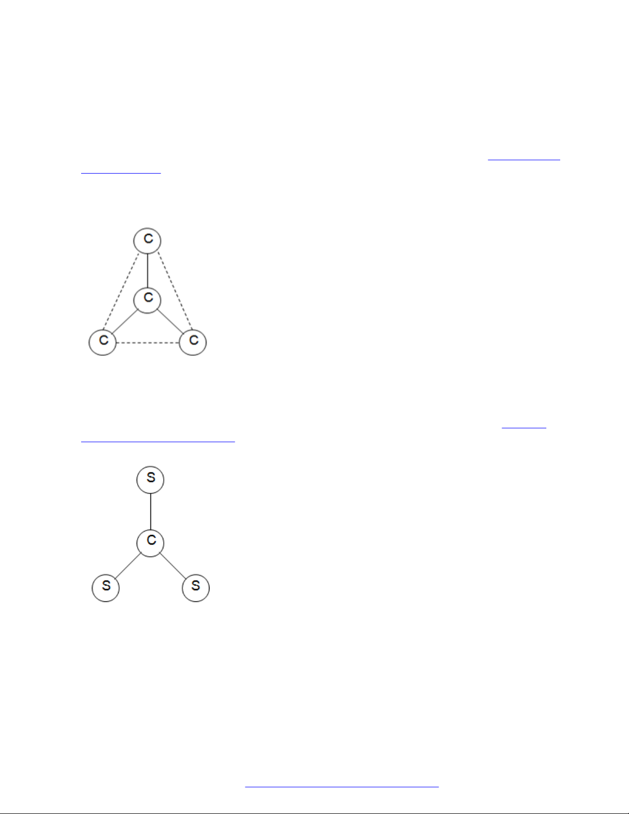
A core network region is the traditional network region and can have multiple direct links with other
network regions. For a diagrammatic representation of core network regions, see
Figure 1: Core
network regions on page 13. The solid lines in the diagram indicate a direct communication path
between two core network regions. The dotted lines indicate an indirect logical communication
path between two core network regions.
Figure 1: Core network regions
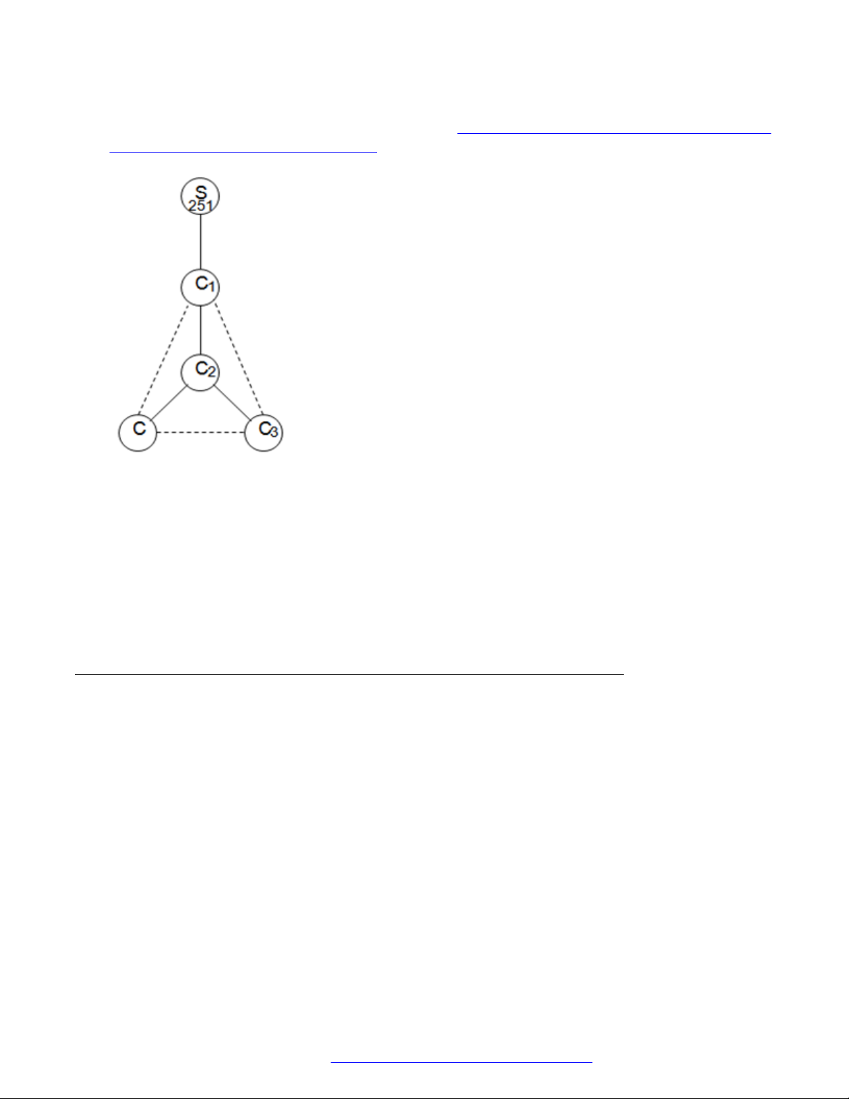
A stub network region must have a single defined pathway to only one core network region. For a
diagrammatic representation of core network regions and stub network regions, see
Figure 2:
Core and stub network regions on page 13.
Figure 2: Core and stub network regions
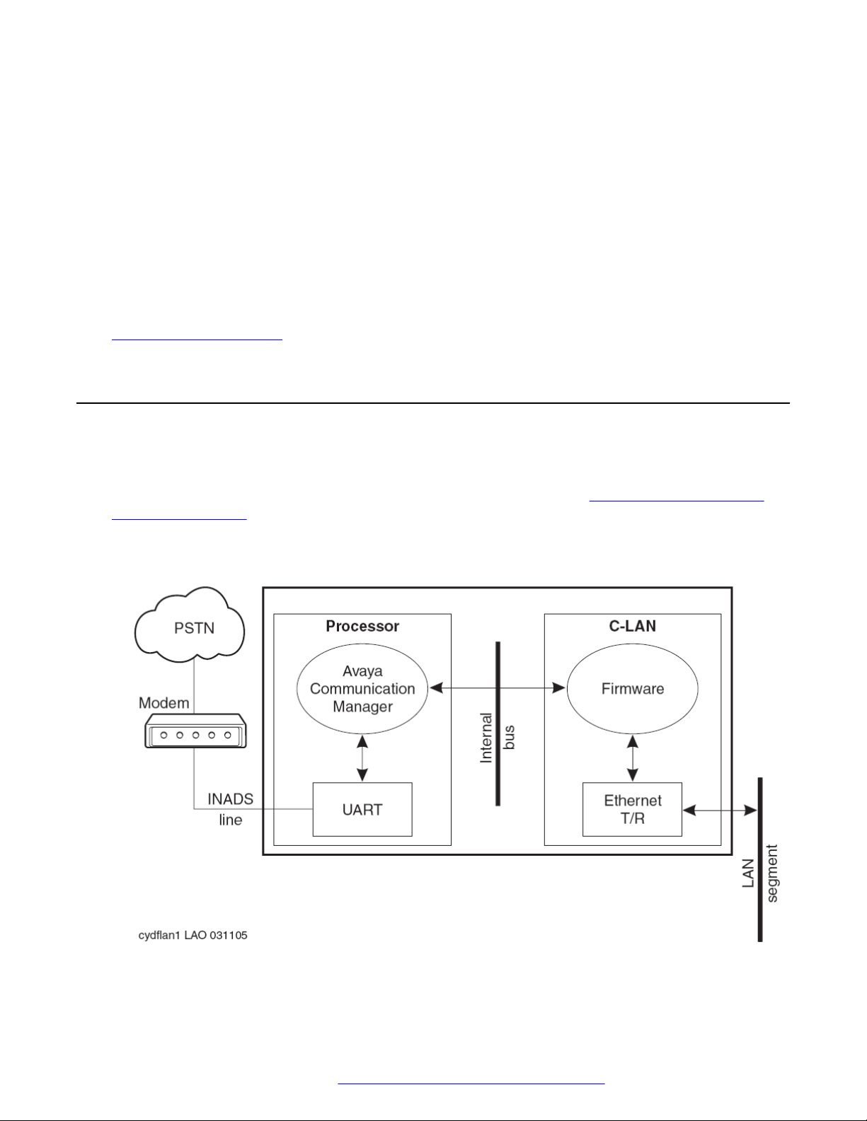
Stub network regions communicate with other network regions using the defined communication
pathways of the core network regions. For example, a scenario where stub network region 251
directly communicates with core network region 1. If stub network region 251 wants to send data
to core network region 3, then stub network region 251 first sends data to core network region 1.
From core network region 1, Communication Manager uses the predefined communication
February 2020 Administering Network Connectivity on Avaya Aura® Communication Manager 13
Comments on this document? infodev@avaya.com
Page 14
Networking Overview
pathway of core network region 1 to reach core network region 3. For a diagrammatic
representation of the communication pathway, see .Figure 3: Communication Pathway from a stub
network region to a core network region on page 14
Figure 3: Communication Pathway from a stub network region to a core network region
The benefit of having a stub network region is that you do not have to configure multiple
communication pathways to different network regions. When you add a stub network region,
administer the communication path only to the core network region to which the stub network
region connects.
You must assign all Communication Manager hardware, such as branch gateways, media
processors, C-LANs, and G650 cabinets to network regions 1 to 250. This assignment must be
done regardless of whether the network region is a core network region or a stub network region.
Features affected by the increase in locations and network regions
The increase in the number of network regions and locations can affect the following features:
• Dial Plan Transparency (DPT): The DPT feature can work in a stub network region only with
endpoints. Stub network regions use the media processing resources of the core network
regions that the stub network regions connect to. Administer the DPT feature in a core
network region that is directly linked with other stub network regions. Only then can the
endpoints in the stub network regions connect to endpoints in other network regions.
• Inter-gateway Alternate Routing (IGAR): Any stub network region from 1 to 250 can use
IGAR if the stub network region contains a branch gateway or a port network. IGAR is
unavailable for stub network regions from 251 to 2000.
• Emergency Calling: When an endpoint in a stub network region dials an emergency number,
Communication Manager analyzes the dialed number. Communication Manager then uses
February 2020 Administering Network Connectivity on Avaya Aura® Communication Manager 14
Comments on this document? infodev@avaya.com
Page 15

Interswitch trunk connections
the ARS location table to route the call to the destination. The call is routed using a
predefined route pattern.
Interswitch trunk connections
You can use the connected switches within an enterprise to communicate easily, regardless of the
location or the communication server that the switches use. Interswitch connections also provide
shared communications resources, such as messaging and call center services.
Switches communicate with each other over trunk connections. Different types of trunks provide
different sets of services. Commonly used trunk types are:
• Central Office (CO) trunks that provide connections to the public telephone network through a
central office.
• H.323 trunks that send voice and fax data over the Internet to other systems with H.323 trunk
capability.
• H.323 trunks that support DCS+ and QSIG signaling.
• Tie trunks that connect switches in a private network.
• SIP trunk equipped with SIP signaling
For more information about the trunk types, see Administering Avaya Aura® Communication
Manager, 03-300509.
IP-connected networks
For more information about IP-connected (IP-PNC) networks, see Chapter 3: Port network
configurations on page 26.
Branch office networks
In Communication Manager environments, MultiVOIP™ gateways provide distributed networking
capabilities to small branch offices of large corporations. MultiVOIP extends the call features of a
centralized Avaya server. MultiVOIP provides local office survivability to branch offices of up to 15
users who use analog or IP telephones.
Control networks
Control networks are networks over which Communication Manager exchanges signaling data
with port networks. Communication Manager exchanges signaling data through the IPSI circuit
packs.
February 2020 Administering Network Connectivity on Avaya Aura® Communication Manager 15
Comments on this document? infodev@avaya.com
Page 16

Networking Overview
Spanning Tree Protocol
Spanning Tree Protocol (STP) is a loop avoidance protocol. If your network does not have loops,
you do not need STP. However, you must always enable STP. If you do not enable STP, all traffic
stops on the network with a loop or with the wrong cable plugged into wrong ports.
However, STP is slow to converge after a network failure and provide a new port into the network.
By default, the speed is ~50 seconds.
A modified version of STP is the Rapid Spanning Tree protocol. Rapid Spanning Tree converges
faster than STP and enables new ports faster than the older protocol. As the Rapid Spanning Tree
protocol works with all Avaya equipment, use the Rapid Spanning Tree protocol.
Inter-Gateway Alternate Routing
With Inter-Gateway Alternate Routing (IGAR), Communication Manager can use the PSTN
instead of the IP-WAN for bearer connections. This feature is beneficial when the IP-WAN cannot
carry the bearer connection for the single-server systems that use the IP-WAN to connect bearer
traffic between port networks or gateways.
Note:
Communication Manager Release 6.3.5 and earlier supported IGAR for analog, DCP, and H.
323 endpoints. Communication Manager Release 6.3.6 extends this support to SIP endpoints.
IGAR requests PSTN to provide bearer connections in any of the following conditions:
• Reaching the number of calls or bandwidth allocated through Call Admission ControlBandwidth Limits (CAC-BL).
• Facing VoIP RTP resource exhaustion in a port network or media gateway.
• Encountering the codec set between a pair of network regions set to pstn.
• Finding forced redirection configured between a pair of network regions.
IGAR provides enhanced Quality of Service (QoS) to large, distributed single-server
configurations. IGAR is intended for configurations where the IP network is not reliable enough to
carry bearer traffic. If you have more than one IP network available, you can use H.323 or SIP
trunks for IGAR instead of the PSTN.
When Communication Manager needs an intergateway connection and adequate IP bandwidth is
unavailable, Communication Manager attempts to substitute a trunk connection for the IP
connection. For example, Communication Manager can substitute a trunk connection in any of the
following situations:
• A user in one Network Region (NR) calls a user in another NR
• A station in one NR bridges on to a call appearance of a station in another NR
• An incoming trunk in one NR routes to a hunt group with agents in another NR
February 2020 Administering Network Connectivity on Avaya Aura® Communication Manager 16
Comments on this document? infodev@avaya.com
Page 17

Interswitch trunk connections
• An announcement or music source from one NR must be played to a party in another NR
Communication Manager attempts to use a trunk for interregion voice bearer connection when the
following five conditions are met:
• An intergateway connection is needed.
• IGAR requests PSTN to provide bearer connections.
• IGAR is enabled for the NRs associated with each end of the call.
• The Enable Inter-Gateway Alternate Routing system parameter is set to y.
• The number of trunks, used by IGAR in each NR, has not reached the limit administered for
that NR.
The SRC PORT TO DEST PORT TALKPATH page of the status station screen shows the IGAR
trunk connectivity for an inter-NR call.
A Trunk Inter-Gateway Connection (IGC) is established using ARS to route a trunk call from one
NR to IGAR Listed Directory Number (LDN) extension administered for another NR. The Trunk
IGC is independent of the call. Therefore, Communication Manager can originate the IGC from the
NR of the calling party to the NR of the called party, or vice versa. Some users use Facility
Restriction Levels or Toll Restriction to determine who gets access to IGAR resources during a
WAN outage. For these users, the calling user is considered the originator of the Trunk IGC for
authorization and routing. For outgoing trunk groups administered to send the Calling Number, the
IGAR Extension in the originating NR is used to create this number using the appropriate
administration.
A few examples of failure scenarios and how Communication Manager handles the scenarios:
• On a direct call, the call continues to the first coverage point of the unreachable called
endpoint. If no coverage path is assigned, the calling party hears a busy tone.
• If the unreachable endpoint is accessed through a coverage path, the coverage point is
skipped.
• If the unreachable endpoint is the next available agent in a hunt group, that agent is
considered unavailable. The system tries to route the call to another agent using the
administered group type, such as Circular distribution and Percent Allocation Distribution.
Dial Plan Transparency
Dial Plan Transparency (DPT) preserves the dial plan when a gateway registers with a Survivable
Remote server or when a port network registers with a Survivable Core server. Port network
registers with a Survivable Core server due to the loss of contact with the primary controller. DPT
establishes a trunk call and reroutes the call over the PSTN to connect endpoints that can no
longer connect over the corporate IP network.
You need not activate DPT in the license file. DPT is a standard feature in Communication
Manager Release 4.0 and later. DPT is similar to IGAR as both provide alternate call routing when
normal connections are unavailable. A major difference is that DPT routes calls between
endpoints that two independent servers control. IGAR routes calls between endpoints that a single
February 2020 Administering Network Connectivity on Avaya Aura® Communication Manager 17
Comments on this document? infodev@avaya.com
Page 18

Networking Overview
server controls. The DPT and IGAR features are independent of each other, but you can activate
both simultaneously.
Limitations of DPT:
• DPT only handles IP network connectivity failures between network regions.
• DPT calls are trunk calls. Therefore, Communication Manager does not support many station
features.
• For Release 4.0, DPT applies only to endpoints that are dialed directly. DPT cannot route
redirected calls or calls to groups.
• DPT cannot reroute calls involving a SIP endpoint that has lost registration with the Session
Manager.
• DPT works only when failover strategies for gateways and port networks, and alternate
gatekeeper lists for IP stations are consistent.
For information about administering DPT, see
Administering DPT on page 150.
Network quality management
A successful Voice over Internet Protocol (VoIP) implementation involves quality of service (QoS)
management that is affected by three major factors:
• Delay: Significant end-to-end delay can cause echo and talker overlap.
• Packet loss: During peak network loads and periods of congestion, voice data packets might
drop.
• Jitter (Delay variability): Data packets arrive at their destination at irregular intervals because
of variable transmission delay over the network.
For more information about these QoS factors and network quality management, see:
• Chapter 6: Voice and Network quality administration on page 119
• Avaya Aura® Solution Design Considerations and Guidelines, 03-603978.
VoIP transmission hardware
The following circuit packs are essential in an Avaya telecommunications network:
• TN799DP control LAN (C-LAN) interface
Provides TCP/IP connectivity over Ethernet between servers and gateways, or Point to Point
Protocol (PPP) between servers and adjuncts.
• TN2312BP IP Server Interface (IPSI)
February 2020 Administering Network Connectivity on Avaya Aura® Communication Manager 18
Comments on this document? infodev@avaya.com
Page 19

VoIP transmission hardware
Transports control messages between servers and port networks.
• TN2302AP IP Media Processor and TN2602AP IP Media Resource 320
Provide high-capacity VoIP audio access to the switch for local stations and outside trunks.
• Branch gateways
Provide:
- Extension of Communication Manager telephony features to branch offices when
controlled by a remote server.
- Standalone telephony systems when controlled by an embedded S8300D Server and
S8300E.
- Survivable Remote server backup for a remote server.
The branch gateways include the G700, G250 Branch Gateway, G350 Branch Gateway,
G430 Branch Gateway G450 Branch Gateway and IG550.
Note:
S8300E supports G430 Branch Gateway and G450 Branch Gateway.
• MM760 VoIP Media Module
Provides another 64 VoIP channel in the G700 motherboard VoIP engine. The MM760 VoIP
Media Module is a clone of the G700.
• Avaya Aura® Media Server
Avaya Aura® Media Server is used by Communication Manager to provide IP audio
capabilities similar to legacy H.248 media gateways or port networks with media processors.
For more information about Avaya hardware devices, see Avaya Aura® Communication Manager
Hardware Description and Reference, 555-245-207.
For information about the administration tasks for this equipment, see VoIP hardware on
page 44.
Processor Ethernet
Processor Ethernet (PE) provides connectivity to IP endpoints, gateways, and adjuncts. The PE
interface is a logical connection in the Communication Manager software that uses a port on the
NIC in the server. The NIC is the s-called native NIC. PE uses the PROCR IP-interface type. You
do not need additional hardware to implement PE.
During the configuration of a server, PE is assigned to a Computer Ethernet (CE). PE and CE
share the same IP address, but are different in nature. The CE interface is a native computer
interface while the PE interface is the logical appearance of the CE interface within the
Communication Manager software. The interface that is assigned to PE can be a control network
or a corporate LAN. The interface that is selected determines which physical port PE uses on the
server.
February 2020 Administering Network Connectivity on Avaya Aura® Communication Manager 19
Comments on this document? infodev@avaya.com
Page 20

Networking Overview
For more information about how to configure the server, see Administering Avaya Aura
Communication Manager, 03-300509.
A Survivable Remote server or a Survivable Core server enables the Processor Ethernet interface
automatically. Using the PE interface, you can register H.248 gateways and H.323 endpoints on
the Survivable Remote server. You must set the H.248 and the H.323 fields on the IP Interface
Procr screen to the default value yes.
In Communication Manager Release 5.2 and later, Branch Gateway and H.323 endpoint
registration on the Survivable Core server is possible. Administer the Enable PE for H.248
Gateways and Enable PE for H.323 Endpoints fields on the Survivable Processor screen of the
main server. The IP Interface Procr screen of the Survivable Core server displays the values that
you administered for the H.248 and H.323 fields.
Important:
Both the Survivable Core server and the Survivable Remote server require the PE interface to
register to the main server. Do not disable the PE interface on either server.
®
Support for Processor Ethernet and port networks on a Survivable Core server
In Communication Manager Release 5.2 and later, the capabilities of survivable core servers are
enhanced to support the connection of IP devices to the Processor Ethernet (PE) interface and to
C-LAN interfaces. C-LAN interfaces are located in G650 gateways. G650 are port networks.
A survivable core server can use the PE interface to support IP devices, such as Branch Gateway,
H.323 Gateways, IP Adjuncts, IP telephones, IP trunks, and SIP trunks. The survivable core
server can optionally control port networks through IPSI simultaneously. Without port networks in
the configuration, the survivable core server can provide the equivalent benefit of a survivable
remote server. The survivable core server can be duplicated, providing more redundancy to the
survivability of the system.
For PE on duplex servers to work, assign the PE interface to the PE Active server IP address and
not the server unique address. The NIC assigned to the Processor Ethernet interface must be on
a LAN connected to the main server.
• If the survivable remote server or the survivable core server registers to the C-LAN on the
main server, the C-LAN must have IP connectivity to the LAN. The LAN must be assigned to
the NIC used for PE on the survivable core server.
• If the survivable remote server or the survivable core server registers to PE on the main
server, PE must have IP connectivity to the LAN. The LAN must be assigned to the NIC used
for PE on the survivable core server.
Firmware for optimal performance
Processor Ethernet on duplex servers works effectively only when the branch gateways and IP
telephones are on the current release of the firmware.
February 2020 Administering Network Connectivity on Avaya Aura® Communication Manager 20
Comments on this document? infodev@avaya.com
Page 21
LAN security
Use the following IP telephone models to ensure optimal system performance when you use
Processor Ethernet on duplex servers:
• 9610, 9620, 9630, 9640, and 9650 telephones with firmware 3.0 or later. Any later 96xx and
96x1 models that support Time to Service (TTS) work optimally.
• 4601+, 4602SW+, 4610SW, 4620SW, 4621SW, 4622SW, and 4625SW Broadcom
telephones with firmware R 2.9 SP1 or later. 46xx telephones are supported if the 46xx
telephones are not in the same subnetwork as the servers.
All other IP telephone models must reregister if a server interchange occurs. The 46xx telephones
reregister if the telephones are in the same subnetwork as the servers.
To ensure that you have the most current versions of firmware, go to the Avaya Support website at
http://support.avaya.com. Click Downloads and select the product.
LAN security
Customers do not want users to access the switch by using the INADS line. When users use the
INADS line, users continue to C-LAN and then gain access to a customer LAN. However, the
Avaya architecture prevents users from accessing the customer LAN.Figure 4: Security-related
system architecture on page 21 shows a high-level switch schematic with a TN799 (C-LAN)
circuit pack.
Figure 4: Security-related system architecture
February 2020 Administering Network Connectivity on Avaya Aura® Communication Manager 21
Comments on this document? infodev@avaya.com
Page 22

Networking Overview
Logging in through the INADS line, customers can access software. Software communicates with
firmware over an internal bus through a limited message set. The two main reasons why a user
cannot go to the customer LAN through the INADS line are:
• A user logging into software cannot get direct access to the C-LAN firmware.
The user can only enter SAT commands that request C-LAN information or configure C-LAN
connections.
• Communication Manager disables the C-LAN application TFTP and cannot enable the
application.
TELNET only interconnects C-LAN Ethernet clients to the system management application
on the switch. FTP exists only as a server and is used only for firmware downloads. FTP
cannot connect to the client network.
Connection Preservation
Communication Manager supports Connection Preservation and Call Preservation for handling
SIP calls. Any SIP telephone connected to Communication Manager through a server that enables
SIP can use this feature. SIP Connection Preservation and Call Preservation are always active.
Call Preservation and Connection Preservation during LAN failure
When near-end failure is detected, the SIP signaling group state changes to the Out-of-service
state. The SIP trunk in the trunk group is in a deactivated state and cannot be used either for
incoming or outgoing calls. Stable or active calls on the SIP trunk are not dropped and are kept in
the In-service/active state. When the active connection is dropped, SIP trunk changes to the Outof-service state. When far-end failure is detected, the SIP signaling group state changes to the
Far-end-bypass state. Stable or active calls are not dropped, and the SIP trunk changes to the
pending-busyout state. When the active connection is dropped, the SIP trunk status changes to
the Out-Of-Serivce/FarEnd-idle state.
Call Preservation and Connection Preservation when LAN connectivity is revived
When the near-end failure ends, the SIP signaling group state changes to the In-service/active
state. Stable or active calls on the SIP-trunk are kept in the In-service/active state. When the farend failure ends, the SIP signaling group state changes to the In-service/active state. The state of
Stable or active calls on the SIP trunk changes from pending-busyout to the In-service/active
state.
The Connection Preservation mechanism also works with DCP and H.323 telephones.
Session refresh handling
When SIP session refresh handling fails, the SIP call is set to Connection Preservation. A net
safety timer keeps the call active for 2 hours. After 2 hours, the call drops unless the user ends the
call before that time.
February 2020 Administering Network Connectivity on Avaya Aura® Communication Manager 22
Comments on this document? infodev@avaya.com
Page 23

Connection Preservation
Connection Preserving Migration
The Connection Preserving Migration (CPM) feature preserves bearer connections while Branch
Gateway migrates from one Communication Manager server to another because of network failure
or server failure. Users on connection preserved calls cannot use features such as Hold,
Conference, or Transfer.
CPM does the following:
• Preserves the audio voice paths.
• Extends the period for recovery operations.
• Continues to function during the complementary recovery strategies of Avaya.
H.248 and H.323 link recovery
The H.248 link connects a Communication Manager server and a gateway. The H.323 link
connects ties a gateway and an H.323-compliant IP endpoint. Link recovery is an automated
method that the gateway uses to reacquire a lost link. The link might be lost from either a primary
call controller or a Survivable Remote server. The H.248 link and the H.323 link provide the
signaling protocol for:
• Call setup
• Call control during the call
• Call tear-down
When the link is out of service, link recovery preserves calls and attempts to reestablish the
original link. If the gateway or the endpoint cannot reconnect to the original server or gateway,
then link recovery automatically attempts to connect with alternate TN799DP (C-LAN) circuit
packs. Link recovery only connects with circuit packs that are within the configuration of the
original server or the Survivable Remote server.
Auto fallback to the primary server
The auto fallback to primary controller feature returns a fragmented network to the primary server
automatically. Fragmented networks have a number of branch gateways that one or more
Survivable Remote servers service. This feature applies to all branch gateways. You can complete
the distributed telephony switch network by automatically migrating the gateways back to the
primary server.
Survivable Remote servers
Survivable remote servers can function as survivable call processing servers for remote or branch
customer locations. Survivable remote servers have a complete set of Communication Manager
features. With the license file, survivable remote servers function as survivable call processors.
If the link between the remote branch gateways and the primary controller breaks, the telephones
and the gateways register with the survivable remote server. Survivable remote servers provide a
backup service to the registered devices and control these devices in a license-error mode.
February 2020 Administering Network Connectivity on Avaya Aura® Communication Manager 23
Comments on this document? infodev@avaya.com
Page 24

Networking Overview
For more information about survivable remote servers, see Avaya Aura® Communication Manager
Hardware Description and Reference, 555-245-207.
Note:
The survivable remote server is also known as Enhanced Local Survivability (ELS).
Survivable core servers
Survivable core servers provide survivability to port networks by putting backup servers in various
locations in the customer network. The backup servers service port networks when:
• The Simplex server fails.
• The Duplex server pair fails.
• connectivity to the main Communication Manager server is lost.
Survivable core servers can be either Simplex or Duplex servers. The servers offer full
Communication Manager functionality in the survivable mode, provided enough connectivity exists
to other Avaya components. For example, endpoints, gateways, and messaging servers.
Standard Local Survivability
Standard Local Survivability (SLS) consists of a module built in to G430 Branch Gateway or G450
Branch Gateway to provide partial backup gateway controller functionality. The gateway provides
the backup function when the connection with the primary controller is lost. To provide
Communication Manager functionality when no link is available to an external controller, you can
use a G430 Branch Gateway or G450 Branch Gateway without a local S8300E.
Support to tandem MIME for PIDF-LO
Communication Manager Release 7.1.1 can tandem Multipurpose Internet Mail Extensions
(MIME) attachments for Presence Information Data Format Location Object (PIDF-LO) in a SIP
message. Communication Manager can also pass the PIDF-LO information in the SIP message.
Support for Channel Type identification over ASAI to CTI application
Communication Manager Release 7.1.1 supports channel type identification over ASAI to a CTI
application. For incoming SIP trunk calls, Communication Manager Release 7.1.1 identifies the
channel type as voice, video, or unknown when the call:
• Enters a monitored Vector Directory Number (VDN) or hunt group (skill/split).
• Is monitored and is alerting at a deskphone or Agent.
February 2020 Administering Network Connectivity on Avaya Aura® Communication Manager 24
Comments on this document? infodev@avaya.com
Page 25

Support for Channel Type identification over ASAI to CTI application
For this feature to work, the CTI link between Communication Manager and Application
Enablement Services must be greater than 7.
This feature might not work or might show an unknown channel type on the CTI application when:
• The Direct Media feature is enabled.
• Communication Manager is not able to identify the channel from the incoming SIP request.
February 2020 Administering Network Connectivity on Avaya Aura® Communication Manager 25
Comments on this document? infodev@avaya.com
Page 26

Chapter 3: Port network configurations
You can control call processing of port networks in various ways by using Communication Manager.
Using only Ethernet connections, you can establish control networks. Over LAN/WAN connections,
you can transmit voice, fax, and TTY. Types of reliability achieved with Duplex servers can include
single control and bearer networks, duplicated control networks, duplicated control and bearer
networks, or a combination of reliabilities.
Types of control networks and the corresponding types of reliability:
• Single control and bearer networks are standard reliability.
• Duplicated control networks are high reliability.
• Duplicated control and bearer networks are critical reliability.
IP port network connectivity
IP port network connectivity allows servers and port networks and Branch Gateways to be
connected over IP networks. Communication Manager uses a proprietary method to package
signaling messages over IP. This method allows deployment of communications systems
throughout a customer’s data network.
For bearer transmission and control signaling from the server, IP port network connectivity (IPPNC) uses LAN or WAN connections between port networks. Each port network must have either
one or two control IPSI circuit packs for control signaling.
Reliability
Reliability is the capability of a Communication Manager configuration to maintain service when
components within the configuration fail. Components that fail might include Ethernet switches,
circuit packs, or gateways. The available reliability levels depend on whether the port networks
use IP-PNC and whether the server is simplex or duplex.
February 2020 Administering Network Connectivity on Avaya Aura® Communication Manager 26
Comments on this document? infodev@avaya.com
Page 27

Simplex server
A Simplex server provides several reliability options.
• Standard reliability:
For IP port network connectivity (IP-PNC), a Simplex server supports a single IPSI for
controlling the IP-PNC port network, TN2302BP, or TN2602AP circuit packs. The circuit
packs are used for the bearer network. However, TN2602AP circuit packs are implemented in
the load-balancing mode only.
• Duplicated bearer reliability:
For IP-PNC, a Simplex server does not support duplicated control. However, IP-PNC port
networks can have duplicated TN2602AP circuit packs to duplicate the bearer connections.
In a port network with duplicated TN2602AP circuit packs, control signaling always occurs
over a direct IPSI connection to the server. A duplicated bearer network that uses TN2602AP
circuit packs is implemented for each port network. Uniform implementation for all port
networks within the configuration is not required.
Reliability
Duplex server
A Duplex server has multiple levels of reliability.
IP port network connectivity
Reliability for Port Networks that use IP port network connectivity (IP-PNC) within a single
Communication Manager configuration is implemented for each Port Network. Uniform
implementation for other IP-PNC Port Networks within the configuration is not required. In
addition, duplicated bearer and duplicated control can be implemented independently of each
other.
An IP-PNC Port Network can have one of the following reliability levels:
• Standard duplicated servers:
A single IPSI provides control signaling between the Port Network and the server. The Port
Network contains only single or load balancing TN2302BP, or TN2602AP circuit pack pairs.
check data accuracy
• Duplicated control:
In addition to the standard duplicated servers, duplicated IPSIs for control reside in each Port
Network. The Port Network contains only single or load balancing TN2302BP, or TN2602AP
circuit pack pairs.
• Single control and duplicated bearer:
In addition to the standard duplicated servers, duplicated TN2602AP circuit packs reside in
each Port Network to provide duplicated bearer.
February 2020 Administering Network Connectivity on Avaya Aura® Communication Manager 27
Comments on this document? infodev@avaya.com
Page 28

Port network configurations
Note:
For duplicated bearer for IP-PNC Port Networks, use duplicated IPSI control.
• Duplicated control and bearer:
In addition to the standard duplicated servers, duplicated IPSIs for control reside in each Port
Network. Duplicated TN2602AP circuit packs reside in each Port Network to provide
duplicated bearer.
Simplex IP-PNC for the single control network
In the IP-PNC configuration, the Simplex server uses IP connections to control call processing on
the port networks. The Simplex server uses an existing VoIP-ready IP infrastructure to send voice
between port networks over the IP network. With this solution, customers save the cost of building
a separate telephony network. In this type of configuration, all port networks are connected to the
server and to each other over the customer network. You can configure up to 64 port networks in
an IP-PNC configuration. Depending on the Ethernet switches to connect to the port networks and
the port network locations, the network can require multiple Ethernet switches to support the port
networks.
G650 Media Gateway: You can use G650 Media Gateway in an IP-PNC network. A G650 port
network can consist of one to five G650 gateways in a stack connected by a TDM or LAN bus
cable. One gateway that functions as a control gateway in position A at the bottom of the stack
contains the TN2312BP IPSI circuit pack. Only G650 Media Gateway is available for new
installations. However, different migrations from older systems are supported.
IP/TDM conversion resource: Each port network must contain at least one TN2302AP IP Media
Interface or TN2602AP IP Media Resource 320 circuit pack. The TN2302AP or TN2602AP circuit
pack provides IP-TDM voice processing for endpoint connections between port networks. You can
insert the circuit packs in any gateway in the port network. Each port network can optionally house
a TN799DP C-LAN circuit pack for control of the:
• G150 Branch Gateway
• G700, G450, G430, G350, and G250 Branch Gateways
• IP endpoints
• Adjunct systems, such as messaging and firmware downloads
Ethernet connections: In the IP-PNC configuration, the Simplex server connects to the gateways
through a single Ethernet switch. Each port network connects to the Simplex server through a
local Ethernet switch. As a result, remote port networks in an IP-PNC configuration over WAN can
require Ethernet switches in addition to the Ethernet switch that supports the Simplex server. You
can administer IP connections to the Simplex server as dedicated private LAN connections or
connections over the customer LAN.
February 2020 Administering Network Connectivity on Avaya Aura® Communication Manager 28
Comments on this document? infodev@avaya.com
Page 29
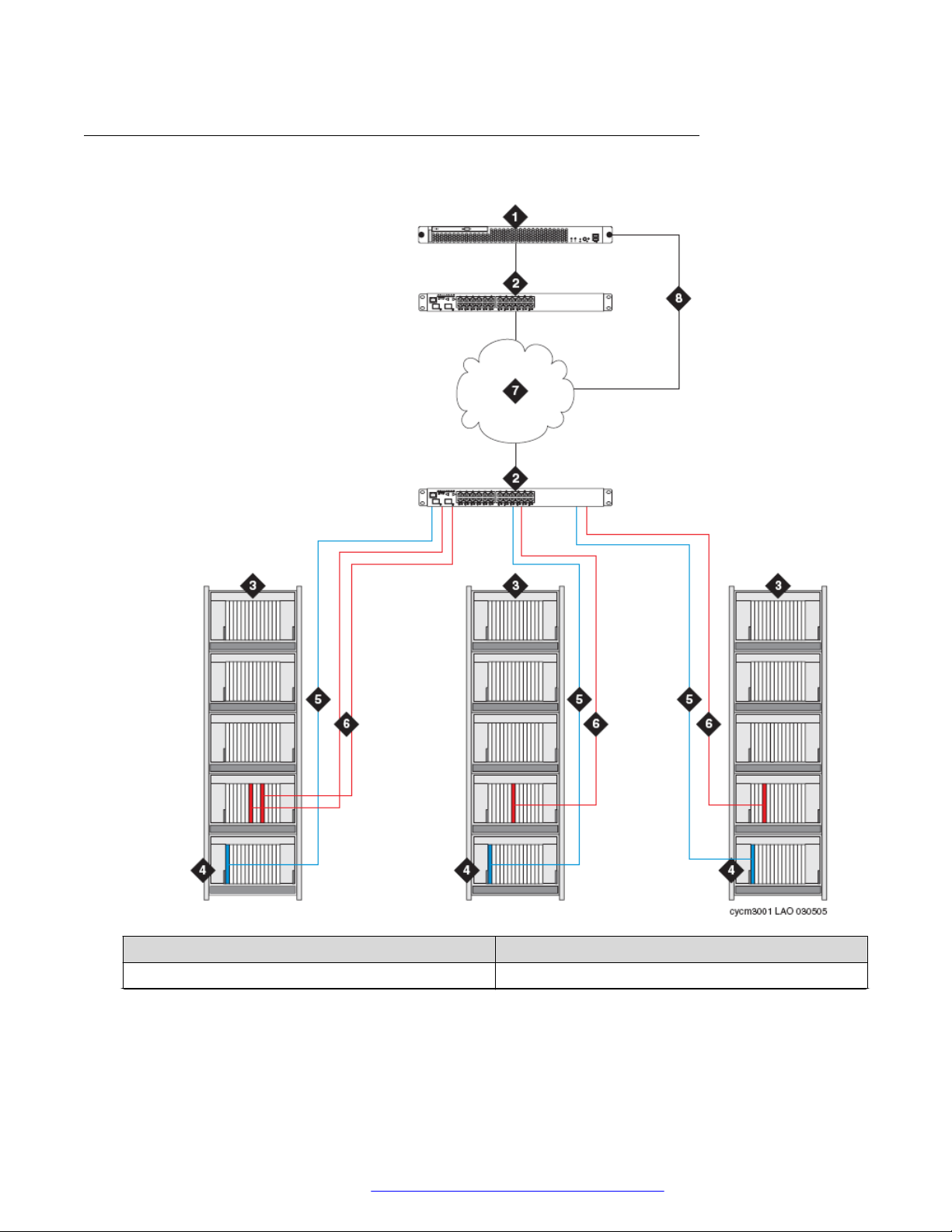
Architecture of simplex server IP-PNC
Simplex IP-PNC for the single control network
Number Description
1 Simplex server C or B.
Table continues…
February 2020 Administering Network Connectivity on Avaya Aura® Communication Manager 29
Comments on this document? infodev@avaya.com
Page 30

Port network configurations
Number Description
2 Ethernet Switch.
For local LAN connections, the same Ethernet
switch can connect both the servers and the
gateways. For remote LAN/WAN connections, the
remote gateways must have an Ethernet switch at
the remote location.
3 Port networks (G650 Media Gateway or stack).
4 Port network control gateway in the A position in the
gateway stack which contains TN2312AP/BP IPSI
circuit pack for IP connection to server.
• A TN2312AP/BP IPSI circuit pack for IP
connection to server.
Note:
For the G650 Media Gateway, you require the
BP version of the TN2312 to provide
environmental maintenance.
5 IPSI-to-server control network connection via
Ethernet switch.
6 LAN connections of TN2302AP IP Media Interface
or TN2602AP IP Media Resource 320 for IP-TDM
voice processing and optional TN799DP C-LAN for
control of IP endpoints
Note:
The number of TN2302AP, TN2602AP, and
TN799DP circuit packs varies, depending on
the number of IP endpoints, port networks, and
adjunct systems. These circuit packs can be
inserted into a port gateway (shown in figure)
or the port network control gateway.
7 Customer LAN/WAN.
8 LAN connections of servers for remote
administration.
Duplicated TN2602AP circuit packs in IP-PNC port networks
For a simplex server, any IP-PNC port network can contain load-balancing or duplicated
TN2602AP circuit packs. However, TN2602AP circuit packs do not need to be implemented
uniformly within the system. Port networks can either have a single TN2602AP circuit pack, loadbalancing TN2602AP circuit packs, or duplicated TN2602AP circuit packs. A simplex server can
have duplicated bearer connections although the server does not support a duplicated control
network.
February 2020 Administering Network Connectivity on Avaya Aura® Communication Manager 30
Comments on this document? infodev@avaya.com
Page 31

Duplex IP-PNC (single control network)
Circuit packs for duplicated bearer connections
For a simplex server, each IP-PNC can contain load-balancing circuit packs, duplicated
TN2602AP circuit packs, or load-balancing TN2302AP circuit packs.
Port networks can have one of the following circuit packs:
• A TN2302AP circuit pack
• A TN2602AP circuit pack
• A combination of TN2302AP and TN2602AP circuit packs
• Load-balancing TN2302AP circuit packs
• Load-balancing TN2602AP circuit packs
• Duplicated TN2602AP circuit packs
A simplex server can have duplicated bearer connections even if the server does not support a
duplicated control network.
Duplex IP-PNC (single control network)
In this configuration, the duplex servers connect to one or more port networks over an Ethernet
connection using an interim Ethernet switch and a dedicated LAN connection or the customer
LAN. Each port network is connected to the Ethernet switch or LAN with a CAT5 cable through a
TN2312AP/BP IP Server Interface (IPSI) card.
With this solution, customers save the cost of building a separate telephony network. In this
configuration, all port networks are connected to the customer network and call control from the
duplex server is also sent over the customer network. You can configure upto 64 port networks in
an IP-PNC configuration.
Only the G650 Media Gateway is available for new installations. However, because different
migrations from older systems are supported, an IP-PNC network supports the G650 Media
Gateway. A G650 port network can consist of one to five G650 gateways in a stack connected by
a TDM/LAN bus cable. A control gateway in position A at the bottom of the stack contains a
TN2312BP IPSI circuit pack.
IP/TDM conversion resource:
Each port network must contain at least one TN2302AP IP Media Interface or TN2602AP IP
Media Resource 320 circuit pack. The TN2302AP or TN2602AP circuit pack provides IP-TDM
voice processing of endpoint connections between port networks. Optionally, one or more
TN799DP C-LAN circuit packs can be present for controlling:
• the G150, G700, G450, G430, G350, and G250 branch gateways
• IP endpoints
February 2020 Administering Network Connectivity on Avaya Aura® Communication Manager 31
Comments on this document? infodev@avaya.com
Page 32

Port network configurations
• adjunct systems such as messaging
• firmware downloads
These circuit packs can be inserted in any gateway in the port network.
Ethernet connections:
In the IP-PNC configuration, the duplex server connects to the gateways through a single Ethernet
switch. Each port network also has a connection to the network or the duplex server through a
local Ethernet switch. Therefore, remote port networks in an IP-PNC configuration over a WAN,
which normally requires routers to complete the connection, require dedicated Ethernet switches.
These Ethernet switches are in addition to the Ethernet switch that supports the duplex server. IP
connections to the duplex server are administered as dedicated private LAN connections or
connections over the customer LAN.
February 2020 Administering Network Connectivity on Avaya Aura® Communication Manager 32
Comments on this document? infodev@avaya.com
Page 33

Duplex IP-PNC (single control network)
Architecture of duplex IP-PNC single control network
Number Description
1 Duplex server.
Table continues…
February 2020 Administering Network Connectivity on Avaya Aura® Communication Manager 33
Comments on this document? infodev@avaya.com
Page 34

Port network configurations
Number Description
2 Ethernet Switch.
For local LAN connections, the same Ethernet
switch can connect both servers and gateways. For
remote LAN/WAN connections, the remote
gateways must have an Ethernet switch at the
remote location.
3 Port networks (G650 Media Gateway or stack).
4 Port network control gateway, in the A position,
which contains a TN2312AP/BP IPSI circuit pack for
IP connection to server.
Note:
For each physical location of a port network or
group of port networks, one port network must
also contain a TN771 Maintenance circuit
pack.
Note:
For the G650 Media Gateway, the BP version
of the TN2312 is required to provide
environmental maintenance.
5 IPSI-to-server control network connection via
Ethernet switch.
6 LAN connections of TN2302AP IP Media Interface
or TN2602AP IP Media Resource 320 for IP-TDM
voice processing and optional TN799DP C-LAN for
control of IP endpoints.
Note:
The number of TN2302AP, TN2602AP, and
TN799DP circuit packs varies, depending on
the number of IP endpoints, port networks, and
adjunct systems. These circuit packs can be
inserted into a port gateway (shown in figure)
or the port network control gateway.
7 Customer LAN/WAN.
8 LAN connections of servers for remote
administration.
9 Duplicated server links, including the link for
translations memory duplication and the link for
control data sharing. The link for memory
duplication is implemented through the DAL2
adapter or, for the duplex server, through software
duplication.
February 2020 Administering Network Connectivity on Avaya Aura® Communication Manager 34
Comments on this document? infodev@avaya.com
Page 35

Duplex server IP-PNC for a duplicated control network
Duplex server IP-PNC for a duplicated control network
The high-reliability configuration of the duplex server IP-PNC is similar to the standard reliability
configuration, except for the following differences:
• Duplicated Ethernet switches are available with each server connected to each Ethernet
switch.
• Each port network has a duplicated TN2312AP or TN2312BP IPSI circuit pack. You can
connect one IPSI circuit pack in each port network through one Ethernet switch and another
IPSI circuit pack through another Ethernet switch.
Architecture of duplex IP-PNC duplicated control network
February 2020 Administering Network Connectivity on Avaya Aura® Communication Manager 35
Comments on this document? infodev@avaya.com
Page 36

Port network configurations
Number Description
1 Duplex server.
2 Ethernet Switch.
For local LAN connections, the same Ethernet
switch can connect both the servers and the
gateways. For remote LAN/WAN connections, the
remote gateways must have an Ethernet switch at
the remote location.
3 Port networks (G650 Media Gateway or stack).
4 Port network control gateway, in the A position,
which contains a TN2312AP/BP IPSI circuit pack for
IP connection to server.
Note:
For each physical location of a port network or
group of port networks, one port network must
also contain a TN771 Maintenance circuit pack
For the G650 Media Gateway, the BP version of the
TN2312 is required to provide environmental
maintenance.
5 Duplicated expansion control gateway, in the B
position, which contains a TN2312AP/BP IPSI
circuit pack for IP connection to control network.
6 IPSI-to-server control network connection via
Ethernet switch.
7 LAN connections of TN2302AP IP Media Interface
or TN2602AP IP Media Resource 320 for IP-TDM
voice processing and optional TN799DP C-LAN for
control of IP endpoints.
Note:
The number of TN2302AP, TN2602AP, and
TN799DP circuit packs varies, depending on
the number of IP endpoints, port networks, and
adjunct systems. These circuit packs can be
inserted into a port gateway as shown in
figure, or the port network control gateway.
8 Customer LAN/WAN.
9 LAN connections of servers for remote
administration.
Table continues…
February 2020 Administering Network Connectivity on Avaya Aura® Communication Manager 36
Comments on this document? infodev@avaya.com
Page 37

Duplex server IP-PNC for a duplicated control and bearer network connection
Number Description
10 Duplicated server links, including the links for
translations memory duplication and control data
sharing. The link for memory duplication is
implemented through the DAL2 adapter or, for the
duplex server, through software duplication.
Duplex server IP-PNC for a duplicated control and bearer
network connection
The critical-reliability configuration of the duplex server IP-PNC is similar to the high-reliability
configuration, except for the following differences:
• Each port network has duplicated TN2602AP IP Media Resource 320 circuit packs. You can
connect one TN2602 circuit pack in each port network through one Ethernet switch and
another TN2602 circuit pack through another Ethernet switch.
• You must install a TN771DP maintenance test circuit pack in each port network that has
duplicated control and bearer network connections.
February 2020 Administering Network Connectivity on Avaya Aura® Communication Manager 37
Comments on this document? infodev@avaya.com
Page 38

Port network configurations
Architecture of duplex IP-PNC duplicated control and duplicated bearer network
Number Description
1 Duplex server.
2 Ethernet Switch.
For local LAN connections, the same Ethernet
switch can connect both the servers and the
gateways. For remote LAN/WAN connections, the
remote gateways must have an Ethernet switch at
the remote location.
Table continues…
February 2020 Administering Network Connectivity on Avaya Aura® Communication Manager 38
Comments on this document? infodev@avaya.com
Page 39

Duplex server IP-PNC for a duplicated control and bearer network connection
Number Description
3 Port networks (G650 Media Gateway or stack).
4 Port network control gateway, in the A position,
which contains:
• A TN2312AP/BP IPSI circuit pack for IP
connection to server.
Note:
For the G650 Media Gateway, the BP version
of the TN2312 is required to provide
environmental maintenance.
• A TN2602AP IP Media Resource 320 for port
network bearer connections over the LAN
Note:
The TN2602AP circuit pack can be placed in
any gateway in the port network. However,
separate the pair of TN2602 circuit packs
between two different gateways when possible.
5 Duplicated expansion control gateway, in the B
position, which contains:
• A TN2312AP/BP IPSI circuit pack for IP
connection to control network.
• A TN2602AP IP Media Resource 320 for port
network bearer connections over the LAN
Note:
The TN2602AP circuit pack can be placed in
any gateway in the port network. However, the
pair of TN2602 circuit packs should be
separated between two different gateways
whenever possible.
6 IPSI-to-server control network connection via
Ethernet switch.
7 LAN connection of the TN799DP C-LAN for control
of IP endpoints
Note:
The number of TN799DP circuit packs varies,
depending on the number of IP endpoints, port
networks, and adjunct systems. These circuit
packs can be inserted into a port carrier as
shown in figure, the port network control
carrier, or the duplicated control carrier.
Table continues…
February 2020 Administering Network Connectivity on Avaya Aura® Communication Manager 39
Comments on this document? infodev@avaya.com
Page 40

Port network configurations
Number Description
8 LAN connections of TN2602AP IP Media Resource
320 circuit packs for IP-TDM voice processing.
9 Customer LAN/WAN.
10 LAN connections of servers for remote
administration.
11 Duplicated server links, including the link for
translations memory duplication and the link for
control data sharing. The link for memory
duplication is implemented through the DAL2
adapter or, for the duplex server, through software
duplication.
Example of IP-PNC port networks with different reliability levels
The following image illustrates a duplex server configuration. This configuration combines
duplicated control and duplicated bearer networks, duplicated control-only network, and single
control network reliability configurations in an IP-PNC network. The port network with a single
control network is labeled as item 11. Other port networks, such as items labeled 3, have
duplicated control networks.
February 2020 Administering Network Connectivity on Avaya Aura® Communication Manager 40
Comments on this document? infodev@avaya.com
Page 41

Example of IP-PNC port networks with different reliability levels
Number Description
1 Duplex server.
2 Ethernet Switch. For local LAN connections, the
same Ethernet switch can connect both the servers
and the gateways. For remote LAN or WAN
connection, the remote gateway must have an
Ethernet switch at the remote location.
3 IP-PNC port networks (G650 Media Gateway or
stack).
4 Control gateway for port network 3 in the A position
in the gateway stack. The control gateway contains
a TN2312AP/BP IPSI circuit pack for IP connection
to the server.
Table continues…
February 2020 Administering Network Connectivity on Avaya Aura® Communication Manager 41
Comments on this document? infodev@avaya.com
Page 42

Port network configurations
Number Description
5 Duplicated port network control gateway for port
network 3, in the B position in the gateway stack.
The control gateway contains a TN2312AP/BP IPSI
circuit pack for IP connection to the control network.
6 IPSI-to-server control network connection via
Ethernet switch.
7 LAN connections of TN2302AP IP Media Interface
or TN2602AP IP Media Resource 320 for IP-TDM
voice processing and optional TN799DP C-LAN for
controlling IP endpoints.
Note:
The number of TN2302AP, TN2602AP, and
TN799DP circuit packs vary, depending on the
number of IP endpoints, port networks, and
adjunct systems. These circuit packs can be
inserted into a port carrier (shown in figure),
the port network control carrier, or the
duplicated control carrier.
8 Customer LAN or WAN.
9 LAN connections of servers for remote
administration.
10 Duplicated server links, including the link for
translation memory duplication and the link for
control data sharing. The link for memory
duplication is implemented through the DAL2
adapter or (for the duplex server) through software
duplication.
February 2020 Administering Network Connectivity on Avaya Aura® Communication Manager 42
Comments on this document? infodev@avaya.com
Page 43

Chapter 4: Converged Networks
Voice over IP converged networks
Until recently, voice, video, and data were delivered over separate, single-purpose networks. A
converged network brings voice, data, and video traffic together on a single IP network. VoIP
technology from Avaya provides a cost-effective and flexible way of building enterprise
communications systems through a converged network.
Some flexible elements of a converged network include:
• Separation of call control and switching functions. See Separation of Bearer and Signaling
Job.
• Different techniques for handling data, voice, and FAX.
• Communications standards and protocols for different network segments.
• Constant and seamless reformatting of data for differing media streams.
Digital data and voice communications superimposed in a converged network compete for
network bandwidth, or the total information throughput that the network can deliver. Data traffic
requires significant network bandwidth for short periods of time, while voice traffic demands a
steady, relatively constant transmission path. Data traffic can tolerate delays, while voice
transmission degrades if delayed. Data networks handle data flow effectively. However, when
digitized voice signals are added to the mix, networks must be managed differently to ensure
constant, real-time transmission needed by voice.
Network assessment
Adding VoIP taxes network resources and performance because VoIP requires dedicated
bandwidth and is more sensitive to network problems than data applications alone. Many
customer IP infrastructures that appear to be stable and perform at acceptable levels might have
performance and stability issues that create problems for Avaya VoIP Solutions. Therefore, Avaya
cannot assure performance and quality without a network assessment even when a customer
network seems ready to support full-duplex VoIP applications.
In Avaya, the network assessment services for VoIP consist of two phases:
• Basic Network Assessment: A high-level LAN and WAN infrastructure evaluation that
determines the suitability of an existing network for VoIP.
February 2020 Administering Network Connectivity on Avaya Aura® Communication Manager 43
Comments on this document? infodev@avaya.com
Page 44

Converged Networks
• Detailed Network Assessment: A detailed analysis of the information gathered in the basic
network assessment to provide functional requirements for the network to implement Avaya
VoIP
.
For more information, see
• The network assessment offer in Avaya Aura® Solution Design Considerations and
Guidelines, 03-603978.
VoIP hardware
VoIP hardware includes the following components:
Universal DS1 circuit packs and MM710 T1/E1Media Module on page 44
•
•
TN799DP Control LAN on page 47
• TN2302AP IP Media Processor on page 51
• TN2602AP IP Media Resource 320 on page 52
• TN2312BP IP Server Interface (IPSI) on page 55
• MM760 VoIP Media Module on page 59
Universal DS1 circuit packs and MM710 T1/E1Media Module
The TN464HP/TN2464CP circuit packs and the MM710 Media Module version 3 and later have
the same functionality as other DS1 circuit packs. The difference is that the TN464HP/TN2464CP
circuit packs and the MM710 Media Module version 3 and later include echo cancellation circuitry
and the DS1 does not. The echo cancellation circuitry offers echo cancellation tail lengths of up to
96 milliseconds (ms). The TN574, TN2313, and TN2464 DS1 circuit packs do not support echo
cancellation.
The TN464HP/TN2464CP and MM710 are for users who encounter echo over circuits connected
to the Direct Distance Dialing (DDD) network. Echo is noticeable when Communication Manager
is configured for ATM, IP, and wideband. With these configurations, the delay between the primary
signal and the echoed signal is greater than with a TDM configuration. In addition, echo can occur
on system interfaces to local service providers that do not routinely install echo cancellation
equipment in all the circuits.
Echo cancellation is a right-to-use software feature that supports voice channels and is not
intended for data. These circuit packs detect a modem tone and turn off echo cancellation during a
data call.
February 2020 Administering Network Connectivity on Avaya Aura® Communication Manager 44
Comments on this document? infodev@avaya.com
Page 45

Turn on echo cancellation
About this task
Use this procedure to verify if the echo cancellation is enabled for TN464HP/TN2464CP circuit
packs and MM710 T1/E1 Media Modules.
Procedure
1. On the SAT screen, type display system-parameters customer-options.
2. Ensure that the following fields are complete:
• Maximum Number of DS1 Boards with Echo Cancellation: Specifies the number of
DS1 boards that have echo cancellation turned on.
• DS1 Echo Cancellation: Specifies whether echo cancellation is enabled. If the value of
this field is y, echo cancellation is enabled.
Note:
The system can display these fields on different pages of the screen.
3. Exit the screen.
VoIP hardware
Echo cancellation on the DS1 circuit pack or MM710 media module
For the TN464HP/TN2464CP circuit packs and MM710 media module, use the following fields on
the DS1 Circuit Pack screen to support echo cancellation:
• Echo Cancellation
• EC Direction
• EC Configuration
When the Echo Cancellation feature is activated on the System-Parameters Customer Options
screen, the system displays the Echo Cancellation field. When the DS1 Echo Cancellation field
is enabled, the system displays the EC Direction and EC Configuration fields.
EC Direction determines the direction from which echo will be eliminated, either inward or
outward. EC Configuration is the set of parameters used when cancelling echo.
This information is stored in firmware on the Universal DS1 circuit pack.
Note:
Any changes made to the echo cancellation settings on the DS1 Circuit Pack screen take
effect immediately.
Administering the DS1 circuit pack and MM710 media module
Procedure
1. Type add ds1 port, where port is the location of the DS1 circuit pack or the MM710 media
module.
February 2020 Administering Network Connectivity on Avaya Aura® Communication Manager 45
Comments on this document? infodev@avaya.com
Page 46

Converged Networks
2. Press Enter.
The system displays the DS1 Circuit Pack screen.
3. In the Echo Cancellation field, type y .
The system enables echo cancellation on the Universal DS-1 circuit pack.
4. In the Echo Direction field, type inward or outward.
The system indicates the direction of the echo that is to be cancelled.
5. In the EC Configuration field, type digits between 1 to 15. The system indicates the set of
parameters used for echo cancellation.
Note:
The system displays the EC Configuration field on the screen only when the Echo
Cancellation field is set to y.
For more information about the fields, see
Avaya Aura® Communication Manager Screen
Reference, 03-602878.
Echo cancellation on trunks
Use the change trunk-group command to turn echo cancellation on or off for each trunk
group. If the DS1 Echo Cancellation trunk group field is y, echo cancellation is applied to every
TN464HP/TN2464CP trunk member in that trunk group. The EC Configuration number
administered on the DS1 Circuit Pack screen for a trunk board determine the echo cancellation
parameters for a trunk member.
Echo cancellation applies to voice channels. The following trunk group types support echo
cancellation:
• CO
• TIE
• ISDN-PRI
• FX
• WATS
• DID
• DIOD
• DMI-BOS
• Tandem
• Access
• APLT
Echo cancellation on a trunk group is administered from the TRUNK FEATURES screen.
February 2020 Administering Network Connectivity on Avaya Aura® Communication Manager 46
Comments on this document? infodev@avaya.com
Page 47

Note:
Changes to echo cancellation settings on the Trunk Features screen do not take effect until:
• A port or trunk group is busied-out or released.
• The SAT command test trunk group is run add period.
• Periodic maintenance is performed.
Administering a trunk group for echo cancellation
Procedure
1. Type change trunk-groupn, where n is the trunk group number.
2. Go to the Trunk Features page.
Note:
Depending on the trunk group type, the system displays different fields on the screen.
VoIP hardware
3. In the
group.
4. Save the changes.
DS1 Echo Cancellation field, type y to enable echo cancellation for each trunk
TN799DP Control LAN
Systems in a private network are interconnected by both tie trunks for voice communications and
data links for control and transparent feature information. Various DS1, IP, and analog trunk circuit
packs provide the voice communications interface. For TCP/IP connectivity, the data-link interface
is provided by a TN799DP Control LAN (C-LAN) circuit pack. For more information about this VoIP
transmission hardware, see
C-LAN handles the data-link signaling information in the Ethernet or point-to-point (PPP)
configuration. The C-LAN circuit pack has one 10/100BaseT Ethernet connection and up to 16
DS0 physical interfaces for PPP connections. C-LAN also extends ISDN capabilities to csi models
by providing packet-bus access.
• In the Ethernet configuration, C-LAN passes the signaling information over a separate
TCP/IP network, usually by a hub or Ethernet switch.
Use an Ethernet switch for optimal performance. For this configuration, install the C-LAN
circuit pack and connect the appropriate pins of the C-LAN I/O field to the hub or Ethernet
switch.
VoIP transmission hardware on page 18 .
• In the PPP configuration, C-LAN passes the data-link signaling to the DS1. The data-link
signaling is then included in the same DS1 bit stream as the DCS voice transmissions.
For this configuration, install the C-LAN circuit pack No other connections are needed. You
must install the appropriate DS1 circuit packs if the circuit packs are not already present.
February 2020 Administering Network Connectivity on Avaya Aura® Communication Manager 47
Comments on this document? infodev@avaya.com
Page 48

Converged Networks
Physical addressing for the C-LAN board
The Address Resolution Protocol (ARP) on the C-LAN circuit pack relates the 32-bit IP address
configured in software to the 48-bit C-LAN circuit pack MAC address. The MAC address is burned
into the board at the factory. The C-LAN board has an ARP table that contains the IP addresses
associated with each hardware address. This table is used to route messages across the network.
Each C-LAN board has one MAC address, one Ethernet address, and up to 16 PPP addresses.
IP addressing techniques for the C-LAN board
C-LAN supports both Classless Inter-domain Routing and Variable-Length Subnet Masks. These
addressing techniques provide greater flexibility in addressing and routing than class addressing
alone.
Installing the TN799DP C-LAN
Before you begin
TCP/IP connections, Ethernet, or PPP require a TN799DP C-LAN circuit pack, unless your system
has embedded Ethernet capabilities. Before you install the C-LAN circuit pack, ensure you
understand the requirements of your LAN.
About this task
Use this procedure to install the TN799DP C-LAN.
Note:
You do not need to switch off the cabinet to install a C-LAN circuit pack.
Procedure
1. Determine the carrier or slot assignments of the circuit packs to be added.
You can insert the C-LAN circuit pack into any port slot.
2. Insert the circuit packs into the slots you determined in Step 1.
Note:
You do not need to switch off the cabinet to install a C-LAN circuit pack.
Connecting C-LAN cables to a hub or Ethernet switch
Before you begin
In the Ethernet configuration, the C-LAN passes the signaling information over a separate TCP/IP
network, usually by a hub or Ethernet switch. Connect the appropriate pins of the C-LAN I/O field
to the hub or Ethernet switch.
Procedure
1. Connect the 259A connector to the backplane of the port slot containing the C-LAN circuit
pack.
2. Connect the Category 5 UTP cable to the 259A connector and a hub or Ethernet switch.
February 2020 Administering Network Connectivity on Avaya Aura® Communication Manager 48
Comments on this document? infodev@avaya.com
Page 49

Port 17 on the C-LAN circuit pack is now connected to the LAN.
Cable connection for C-LAN connectivity
VoIP hardware
Name Description
1 259A Connector
2 Category 5 UTP Cable with a maximum length of
100 m
3 Ethernet switch
LAN default gateway
On LANs that connect to other networks or subnetworks, define a default gateway. The default
gateway node is a routing device that is connected to different networks or subnetworks. Any
packets addressed to a different subnetwork, and for which no explicit IP route is defined, are sent
to the default gateway node.
February 2020 Administering Network Connectivity on Avaya Aura® Communication Manager 49
Comments on this document? infodev@avaya.com
Page 50

Converged Networks
You must use the IP Interfaces screen to administer a node such as C-LAN port, PROCR, or IP
Interface port, as the default gateway.
The default node on the Node Names screen is a display-only entry with IP address 0.0.0.0. The
IP address 0.0.0.0 functions as a variable that takes on unknown addresses as values. While
setting up the default IP route, any address that the C-LAN cannot process is substituted for the
default address in the default IP route.
Alternate Gatekeeper and C-LAN load balancing
Alternate Gatekeeper gives IP endpoints a list of available C-LAN circuit packs. Alternate
Gatekeeper addresses and C-LAN load-balancing spread IP endpoint registration across more
than one C-LAN circuit pack. The C-LAN load-balancing algorithm allocates endpoint registrations
within a network region to the C-LAN with the least number of sockets in use. Using this C-LAN
load-balancing algorithm increases system performance and reliability.
The software registers with the original C-LAN circuit pack IP address. Then the software sends
back the IP addresses of all C-LAN circuit packs in the network region of the IP endpoint. If the
network connection to one C-LAN circuit pack fails, the IP endpoint reregisters with a different CLAN. If the system uses network regions based on the IP address, the software also sends the IP
addresses of C-LANs in interconnected regions. These alternate C-LAN addresses are also called
gatekeeper addresses. These addresses can be used when the data network carrying the call
signaling from the original C-LAN circuit pack fails.
IP telephones can be programmed to search for a gatekeeper independently of load balancing.
The IP telephone accepts gatekeeper addresses in the message from the Dynamic Host
Configuration Protocol (DHCP) server. It also accepts addresses in the script downloaded from the
Trivial File Transfer Protocol (TFTP) server. too long If the telephone cannot contact the first
gatekeeper address, the telephone uses an alternate address. If the first gatekeeper rejects the
extension and password , the IP phone contacts the next gatekeeper. The number of gatekeeper
addresses that the telephone accepts depends on the length of the addresses administered on the
DHCP server.
Note:
A single Alternate Gatekeeper list is usually used in configurations with multiple servers. In
this case, the DHCP server sends the same Alternate Gatekeeper list to all IP endpoints.
However, if an IP endpoint is unable to register with some of the gatekeepers in the list, a
registration attempt to those gatekeepers is rejected.
C-LAN load balancing and alternate gatekeeper addresses require IP stations that accept multiple
IP addresses, such as:
• IP telephone
• IP softphone
• Avaya IP Agent
February 2020 Administering Network Connectivity on Avaya Aura® Communication Manager 50
Comments on this document? infodev@avaya.com
Page 51

Endpoint capabilities
Table 1: Endpoint capabilities
VoIP hardware
Endpoint Number of
Gatekeepers
IP Telephone 1
8
10
72
IP Softphone R5 30 Manually through options or properties of the IP Softphone after
IP Agent R3 30 Manually through options or properties of the IP agent after
Settings
Default DNS name AvayaCallServer, or manually, one fixed IP
address.
Through DHCP-DNS names or fixed IP addresses. DHCP limits
all options to 255 bytes.
Through TFTP-DNS names or fixed IP addresses. TFTP
overwrites any gatekeepers provided by DHCP.
Fixed IP addresses from Communication Manager.
Communication Manager 2.0 and later supersede any
gatekeeper address provided earlier.
the IP Softphone is installed.
installation, or from Communication Manager.
Note:
DHCP servers send a list of alternate gatekeeper and C-LAN addresses to the IP Telephone
endpoint. A hacker can send a false request and thereby get IP addresses from the DHCP
server. However, the alternate gatekeeper IP addresses are sent only to an endpoint that
successfully registers.
TN2302AP IP Media Processor
Use the TN2302AP IP Media Processor to send voice and FAX data with non-DCS signaling over
IP connections. This Media Processor also transmits voice and Fax data for H.323 multimedia
applications in H.323 V2 compliant endpoints.
The TN2302AP IP Media Processor provides port network connectivity for an IP-connected
configuration. The TN2302AP IP Media Processor includes a 10/100BaseT Ethernet interface to
support H.323 endpoints for IP trunks and H.323 endpoints. The TN2302AP IP Media Processor
design improves voice quality through dynamic jitter buffers.
The TN2302AP IP Media Processor also performs the following functions:
• Echo cancellation
• Silence suppression
• DTMF detection
• Conferencing
February 2020 Administering Network Connectivity on Avaya Aura® Communication Manager 51
Comments on this document? infodev@avaya.com
Page 52

Converged Networks
The TN2302AP IP Media Processor supports the following codecs:
• G.711 (mu-law or a-law, 64 Kbps)
• G.723.1 (6.3 Kbps or 5.3 Kbps audio)
• G.729 (8 Kbps audio)
The TN2302AP IP Media Processor also supports FAX detection and conversion between these
codecs. remove space before the period
TN2302AP transmission interface
The TN2302AP IP Media Processor uses dynamic jitter buffers to provide improved voice quality.
The digital signal processors (DSPs) of the TN2302AP insert the following loss or gain by default:
• 5.0 dB of loss in the signal from the IP endpoints
• 5.0 dB of gain in the signal to the IP endpoints
Based on the country code on the terminal-parameters screen, system administrators can
administer the loss or gain.
TN2302AP hairpinning
The TN2302AP IP Media Processor supports 64 ports of shallow hairpin. IP packets that do not
require speech codec transcoding can be looped back at the UDP/IP layers with a change of
address. By looping back , you can reduce delay and make DSP resources available.
TN2302AP ports
The TN2302AP IP Media Processor is a service circuit pack, not a trunk circuit pack. Therefore,
an H.323 tie trunk cannot be used for facility test calls. Use the ping command to test the
TN2302AP ports.
TN2602AP IP Media Resource 320
For local stations and outside trunks, the TN2602AP IP Media Resource 320 provides highcapacity voice over Internet protocol (VoIP) audio access to the switch . The IP Media Resource
320 provides audio processing for the following types of calls:
• TDM-to-IP and IP-to-TDM
• IP-to-IP
The TN2602AP IP Media Resource 320 circuit pack has two capacity options, both of which are
determined by the license file installed on Communication Manager:
• 320 voice channels, considered the standard IP Media Resource 320
• 80 voice channels, considered the low-density IP Media Resource 320
The port network can hold only two TN2602AP circuit packs.
February 2020 Administering Network Connectivity on Avaya Aura® Communication Manager 52
Comments on this document? infodev@avaya.com
Page 53

VoIP hardware
Note:
CMC1 and G600 branch gateways do not support the TN2602AP IP Media Resource 320.
Load balancing
For load balancing, up to two TN2602AP circuit packs can be installed in a single port network.
The TN2602AP circuit pack is also compatible with and can share load balancing with the TN2302
and TN802B IP Media Processor circuit packs. The actual capacity can be affected by a variety of
factors, including the codec used for a call and fax support.
Note:
When you use two TN2602AP circuit packs, each with 320 voice channels, for load balancing
within a port network, you get 484 voice channels. This limit for the number of voice channels
depends on the maximum number of time slots available for a port network, that is 484.
Bearer duplication
You can install two TN2602AP circuit packs in a single port network to achieve duplication of the
bearer network. In this configuration, one TN2602AP is an active IP media processor and the
other one is a standby IP media processor. If the active media processor or connections to the
media processor fail, active connections failover to the standby media processor and remain
active. This duplication prevents active calls in progress from being dropped during failure. The
interchange between duplicated circuit packs affects only the port network in which the circuit
packs reside.
Note:
The 4606, 4612, and 4624 IP telephones do not support the bearer duplication feature of the
TN2602AP circuit pack. If these telephones are used while an interchange from the active to
the standby media processor is in process, then calls might be dropped.
Virtual IP and MAC addresses to enable bearer duplication
Duplicated TN2602AP circuit packs in a port network share a virtual IP address and a virtual MAC
address. The currently active TN2602 owns these virtual addresses. Each TN2602 also has a real
IP address. All bearer packets sent to a port network that contains duplicated TN2602AP circuit
packs are sent to the virtual IP address of the TN2602 pair in that port network. The bearer
packets are sent regardless of whether the packets originate from TN2602s in other port networks
or from IP telephones or gateways. The active TN2602AP circuit pack receives those packets.
During failover to the standby TN2602, the TN2602s negotiate with each other to determine which
TN2602 is active and which is standby. State-of-health, call state, and encryption information is
shared between TN2602s during this negotiation. The newly active TN2602AP circuit pack sends
a gratuitous address resolution protocol (ARP) request. With this ARP request, the circuit pack
ensures that the LAN infrastructure is updated appropriately with the location of the active
TN2602. Other devices within the LAN update the old mapping in ARP cache with the new
mapping.
February 2020 Administering Network Connectivity on Avaya Aura® Communication Manager 53
Comments on this document? infodev@avaya.com
Page 54

Converged Networks
Requirements for bearer duplication
The Communication Manager license file must have entries for each circuit pack. The entries must
have identical voice channels enabled. In addition, both circuit packs must have the latest
firmware that supports bearer duplication.
Duplicated TN2602AP circuit packs must be in the same subnet. The Ethernet switch or switches
that the circuit packs connect to must also be in the same subnet. Ethernet switches can use
signals from the TN2602AP firmware to identify the MAC address of the active circuit pack when
switches share subnets. This identification process provides a consistent virtual interface for calls.
Duplication and load balancing
A single port network can have only up to two TN2602AP circuit packs. Therefore, the port
network can only have either two duplicated TN2602AP circuit packs or two load balancing
TN2602AP circuit packs. However, in a Communication Manager configuration, some port
networks can have a duplicated pair of TN2602AP circuit packs and other port networks can have
a load balancing pair of TN2602AP circuit packs. Some port networks can also have a single
TN2602AP circuit pack or none.
Note:
A pair of TN2602AP circuit packs previously used for load balancing can be readministered to
be used for bearer duplication. After readministration, only the voice channels of the active
circuit pack can be used. For example, in two TN2602 AP circuit packs in a load balancing
configuration with 80 voice channels in each, iff you readminister the circuit packs to be in the
bearer duplication mode, only 80 channels are available. Similarly, in two TN2602 AP circuit
packs in a load balancing configuration with 320 voice channels in each, if you readminister
the circuit packs to be in bearer duplication mode, only 320 channels are available.
TN2602AP IP Media Resource 320 features
The IP Media Resource 320 supports hairpin connections and the shuffling of calls between TDM
connections and IP-to-IP direct connections. The IP Media Resource 320 can also perform the
following functions:
• Echo cancellation
• Silence suppression
• Adaptive jitter buffer of up to 320 milliseconds
• Dual-tone multifrequency (DTMF) detection
• AEA Version 2 and AES media encryption
• Conferencing
• QOS tagging mechanisms in layer 2 and 3 switching (Diff Serv Code Point [DSCP] and
802.1pQ layer 2 QoS)
• RSVP protocol
February 2020 Administering Network Connectivity on Avaya Aura® Communication Manager 54
Comments on this document? infodev@avaya.com
Page 55

VoIP hardware
The TN2602AP IP Media Resource 320 circuit pack supports the following codecs for voice,
conversion between codecs, and fax detection:
• G.711, A-law or Mu-law, 64 kbps
• G.726A 32 kbps
• G.729 A/AB, 8 kbps audio
The TN2602AP also supports transport of the following devices:
• Fax, Teletypewriter device (TTY), and modem calls using the pass-through mode
• Fax, V.32 modem, and TTY calls using the proprietary relay mode
Note:
V.32 modem relay is needed primarily for secure SCIP telephones, formerly known as
Future Narrowband Digital Terminal (FNBDT) telephones, and STE BRI telephones.
• T.38 fax over the Internet, including endpoints connected to non-Avaya systems
• 64-kbps clear channel transport in support of firmware downloads, BRI secure telephones,
and data appliances
Firmware download
The IP Media Resource 320 can serve as an FTP or SFTP server for firmware downloads.
However, only authorized services personnel can activate and use this capability.
As with the TN2302AP IP Media Processor, firmware upgrades of the TN2602AP circuit pack are
not call maintaining. However, by using the campon-busyout media-processor command, a
single or load balanced TN2602AP circuit pack can be busied out without dropping calls, and then
upgraded. In addition, with duplicated TN2602AP circuit packs, the standby TN2602AP circuit
pack can be upgraded first, and then the circuit packs can be interchanged. The active circuit pack
becomes the standby and can then be busied out and upgraded without dropping calls.
I/O adapter
The TN2602AP IP Media Resource 320 circuit pack has a services Ethernet port in the faceplate.
The TN2602AP circuit pack requires an input/output adapter that provides for one RS-232 serial
port and two 10/100 Mbps Ethernet ports for LAN connections. However, only the first Ethernet
port is used. This Ethernet connection is made at the back of the IP Media Resource 320 slot.
Note:
The TN2302AP IP Media Processor can also use this I/O adapter.
TN2312BP IP Server Interface
In configurations with the duplex server controlling gateways, the bearer paths and the control
paths are separate. Control information for port networks travel over a LAN through the Ethernet
switch. The control information ends on the duplex server at one end and on a TN2312BP IP
February 2020 Administering Network Connectivity on Avaya Aura® Communication Manager 55
Comments on this document? infodev@avaya.com
Page 56

Converged Networks
Server Interface (IPSI) on the other end. Each IPSI can control up to five port networks by
tunneling control messages over the Center-Stage or ATM network to port networks without IPSIs.
Note:
You cannot put IPSIs in a port network that has a Stratum-3 clock interface. Also, you cannot
put IPSIs in a remote port network that is using a DS1 converter.
In configurations that use a dedicated LAN for the control path, IPSI IP addresses are usually
assigned automatically using DHCP service from the server. Also, a dedicated IPSI Ethernet
connection to a laptop can be used to assign static IP addresses or for maintenance. In
configurations using the customers LAN, only static addressing is supported.
For information about installing and upgrading duplex servers and IPSI configurations, see the
Avaya S8300, Simplex and Duplex server Library CD, 555-233-825.
You can use the status qos-parameters ipserver-interface command to view the ISPI
settings. The board location must be a valid TN2312 or TN8412 board location. For more
information about the status qos-parameters ipserver-interface command, see
Maintenance Commands for Avaya Aura® Communication Manager, Branch Gateways and
Servers, 03-300431.
Detailed description
In Communication Manager Release 5.2, an administrator can manage the following IPSI-related
parameters using a SAT interface or System Management Interface:
• On the System Parameters IP Server Interface screen, set the values of the DiffServ and
802.1p QoS parameter fields . The default value for DiffServ is 46 and the value for 802.1p
is 6.
• Download QoS parameters to all IPSI boards. By default, the add ipserver-interface
or change ipserver-interface command prepopulates the QoS parameters when IPSI
boards are added.
• On the IP Server Interface screen, set the values of Auto, Speed, or Duplex Ethernet
interface fields . Speed and Duplex fields display on the IPSI screen if the Auto field is set to
n.
• On the IP Server Interface screen, change IPSI IP addresses in the IP Address, Subnet
Mask, and Gateway address fields .
Note:
Set the initial IPSI IP address manually by locally logging on to each IPSI board through
a telnet or an ssh connection. This topic has actions; rewrite as a task topic with a
suitable heading.
February 2020 Administering Network Connectivity on Avaya Aura® Communication Manager 56
Comments on this document? infodev@avaya.com
Page 57

VoIP hardware
Firmware
The IPSI and Communication Manager use a capabilities exchange message to determine
whether an IPSI/SIPI board can support the IPSI administration feature. To support the capabilities
exchange message after the port network is in service, you require:
• IPSI firmware version 46 or later
• SIPI firmware version 16 or later
IP Server Interface parameters
The IPSI sends QoS parameters, Ethernet settings, and IP address information to Communication
Manager as specified in the IP Server Interface parameters table. The exchange of information is
shared on socket creation.
Warning:
The Ethernet interface settings Auto, Speed, and Duplex, or the IPSI IP address settings IP
Address, Subnet Mask, and Gateway address must match with the network entity that the
IPSI is communicating with. In case these parameters do not match, network communication
can stop. To recover the settings, you must go to the physical site of the IPSI, log in to the
IPSI services port, and change the settings.
Table 2: IP Server Interface parameters
Description
QoS parameters:
On the System Management
Interface, select Installation >
Configure Server. and enable VLAN
802.1q priority tagging.
On the IP Server Interface screen,
you can use System Level Parameter
Values and update the following
parameters:
802.1p
DiffServ
Ethernet interface settings:
On the IP Server Interface screen,
update values for the following
parameters:
Auto
Conditions/Comments Required board is busied
out
No
Reset the IPSI board for Auto,
Speed, and Duplex values to take
effect.
Yes
Speed
Duplex
Table continues…
February 2020 Administering Network Connectivity on Avaya Aura® Communication Manager 57
Comments on this document? infodev@avaya.com
Page 58

Converged Networks
Description Conditions/Comments Required board is busied
out
IP Address information:
On the IP Server Interface screen,
update values for the following
parameters:
IPSI IP Address
Subnet Mask
Gateway address
Reset the IPSI board for IP
Address, Subnet Mask, and
Gateway address values to take
effect.
Yes
Communication Manager alarm on settings mismatch
Communication Manager compares the values administered on SAT with the reported IPSI board
values. The system generates a warning alarm if Communication Manager finds any
discrepancies in the following values:
• 802.1p
• DiffServ
• Ethernet Auto
• Ethernet Speed
• Ethernet Duplex
You can view the alarm using the display alarms command or by entering error type 1 on the
Display Errors screen.
Note:
Discrepancy between the SAT administration and the IPSI board values can happen if you
change any IPSI board values using the CLI.
You can clear the alarm in one of the following ways:
• Set the correct values, and busyout or release the IPSI board.
• Change the values on the IP Server Interface screen, and submit the screen.
• Change the values on the affected IPSI board using the CLI .
Default settings of IPSI QoS parameters
In the IPSI administration feature, QoS settings are standardized to communicate between the
IPSI and Communication Manager. If required, you can administer the QoS parameters on the
Change IP Server Interface screen. The QoS default settings are shown in the following table:
February 2020 Administering Network Connectivity on Avaya Aura® Communication Manager 58
Comments on this document? infodev@avaya.com
Page 59

Table 3: QoS default settings
Description Default settings Location
Communication
Manager to IPSI
IPSI to
Communication
Manager
DiffServ = 46 DiffServ field on change ipserver-
interface SAT screen.
802.1p = 6 802.1p field on change ipserver-
interface SAT screen.
802.1p/Q enabled = no On the System Management Interface,
select Installation > Configure Server. The
system displays the Configure Server
wizard. Click Configure Interface.
DiffServ = 46 (vintage >= 38)
DiffServ = 40 (vintage < 38)
802.1p = 6 802.1p field on change ipserver-
802.1p/Q enable = no IPSI CLI interface.
DiffServ field on change ipserver-
interface SAT screen.
Or IPSI CLI interface.
interface SAT screen.
Or IPSI CLI interface.
VoIP hardware
Backward compatibility
The IPSI administration interoperates with Communication Manager Release 5.0 or earlier by
using the preexisting QoS and administration interface. An IPSI uses the IPSI administration
feature if IPSI firmware version is 46 or later, SIPI firmware version is 16 or later, and the
Communication Manager system supports Release 5.2 features.
The IPSI administration feature with Communication Manager Release 5.2 works with earlier IPSI
boards as follows:
• Communication Manager assesses the administration capability of an IPSI board based on
the capabilities exchange message.
• In general, if an older IPSI cannot support this feature, then you must administer that IPSI by
using the CLI . If Communication Manager cannot exchange the capabilities message with an
older IPSI board, the following happens:
- Communication Manager stops sending any IPSI QoS or Ethernet settings to IPSI.
- Communication Manager stops receiving the IPSI QoS or Ethernet settings from IPSI.
- IPSI reports the IPSI status on the IP Server Interface screen.
MM760 VoIP Media Module
The Avaya MM760 Media Module is a clone of the motherboard VoIP engine. MM760 provides the
audio bearer channels for VoIP calls and is controlled by the G700. Based on system
administration of audio codecs, MM760 can handle either 64 or 32 simultaneous channels of H.
323 audio processing. If the IP Parameters screen specifies only G.711 mu-law or G.711 a-law as
February 2020 Administering Network Connectivity on Avaya Aura® Communication Manager 59
Comments on this document? infodev@avaya.com
Page 60

Converged Networks
the audio codecs, MM760 can service 64 channels. If any other codec type, such as G.723-5.3K,
G.723-6.3K, or G.729, is administered, MM760 can only service 32 channels. These call types can
be mixed on the same resource. In other words, the simultaneous call capacity of the resource is
64 G.711 Equivalent Calls.
Note:
Customers who want an essentially nonblocking system must add an additional MM760 Media
Module. An additional MM760 Media Module is required only if customers use more than two
MM710 Media Modules in a single chassis. The extra MM760 provides an additional 64
channels and is supported by only G700 Branch Gateway. MM760 is not supported by G250,
G350, G430, and G450 branch gateways.
MM760 Ethernet interface
MM760 must have an Ethernet address. The MM760 requires a 10/100Base T Ethernet interface
to support H.323 endpoints for Avaya IP trunks and stations from another G700 Branch Gateway.
The G700 Branch Gateway supports MM760, but G250, G350, G430, and G450 branch gateways
do not.
Voice compression on MM760
MM760 supports on-board resources for compression and decompression of voice. The
compression and decompression is for A and µ-law G.711, G.729, G.729B, and 5.3K and 6.3K G.
723. The VoIP engine supports the following functionality:
• RTP and RTCP interfaces
• Dynamic jitter buffers
• DTMF detection
• Hybrid echo cancellation
• Silence suppression
• Comfort noise generation
• Packet loss concealment
MM760 also supports transport of the following:
• Teletypewriter device (TTY) tone relay over the Internet
• Faxes over a corporate IP intranet: Only on Avaya telecommunications and networking
equipment.
Security alert:
Faxes sent to non-Avaya endpoints cannot be encrypted.
• Modem tones over a corporate IP intranet: Only on Avaya telecommunications and
networking equipment.
February 2020 Administering Network Connectivity on Avaya Aura® Communication Manager 60
Comments on this document? infodev@avaya.com
Page 61

Avaya gateways
Avaya gateways
The following documents provide additional information about administration of Avaya gateways:
• Administering Avaya Aura® Communication Manager, 03-300509
• Upgrading, Migrating, and Converting Servers and Branch Gateways, 03-300412
Avaya Aura® Media Server
For more information about Avaya Aura® Media Server, see Avaya Aura® Communication
Manager Feature Description and Implementation, 555-245-205
IP trunks
The following sections describe the administration of IP trunks:
• SIP tunks
• H.323 trunks
SIP trunks
Session Initiation Protocol (SIP) is an endpoint-oriented messaging standard defined by the
Internet Engineering Task Force (IETF). SIP trunking functionality is available on any Linux-based
server. Linux servers function as Plain Old Telephone Service (POTS) gateways. These servers
support name and number delivery among the various non-SIP endpoints, such as analog, DCP,
or H.323 stations, and analog, digital or IP trunks that Communication Manager supports. These
servers also support name and number delivery between SIP-enabled endpoints, such as the
Avaya 4600-series SIP Telephones. In addition to calling capabilities, IP Softphone Release 5 and
later include optional instant messaging client software, which is a SIP-enabled application. IP
Softphone Release 5 also continues full support of the existing H.323 standard for call control.
Avaya SIP Softphone Release 2 and later release fully support SIP for voice call control, instant
messaging, and presence.
Communication Manager assigns two types of numbering to an incoming SIP trunk call:
• Private numbering: If the domain of the PAI, From, or Contact header in an incoming INVITE
matches the authoritative domain of the called party network region.
• Public numbering: If the domain of the PAI, From, or Contact header in an incoming INVITE
does not match the authoritative domain of the called party network region.
February 2020 Administering Network Connectivity on Avaya Aura® Communication Manager 61
Comments on this document? infodev@avaya.com
Page 62

Converged Networks
Public and private numbering plans are important when the incoming SIP trunk call is routed back
over an ISDN trunk group.
ISDN defines numbering plans (NPI) and types of number (TON) within those plans.
Table 4: NPI and the values of TON within the plans
Number length NPI=Public NPI=Private NPI=Unknown
Longest TON=international TON=Level 2 n/a
Middle TON=national TON=Level 1 n/a
Shortest TON=Local TON=Level 0 n/a
“don’t know” TON=Unknown TON=Unknown TON=Unknown
If the caller does not know or does not want to specify the TON or NPI, Communication Manager
can set that value to Unknown. When an incoming SIP call is routed to an ISDN network,
Communication Manager always sets the TON to Unknown.
Creating a SIP trunk signaling group
Procedure
1. Type add signaling-group n, where n is the signaling group number.
The system displays the Signaling Group screen.
2. In the Group Type field, type sip.
3. In the Near-end Node Name field, type the node name of the procr.
The node names are administered on the Node Names screen and the IP Interfaces
screen.
4. In the Far-end Node Name field, type the far end Session Manager name.
Leave this field blank when the signaling group is associated with an unspecified
destination.
5. In the Near-end Listen Port field, type the port number depending on the transport
method.
For example, enter 5060 for TCP/UDP and 5061 for TLS.
6. In the Far-end Listen Port field, enter the number entered in the Near-end Listen Port
field.
7. In the Far-end Network Region field, enter a value from 1 to 250 or leave the field blank.
Identify the network assigned to the far end of the trunk group. The far-end network region
is used to obtain the codec set for negotiation of trunk bearer capability.
8. In the Far-end Domain field, type the name of the IP domain that is assigned to the far
end of the signaling group.
February 2020 Administering Network Connectivity on Avaya Aura® Communication Manager 62
Comments on this document? infodev@avaya.com
Page 63

H.323 trunks
For example, to route Session Manager calls within an enterprise, the domain assigned to
the proxy server is used. For external SIP calling, the domain name can be the name of
the SIP service provider.
Leave this field blank when you do not know the far-end domain.
9. In the DTMF Over IP field, specify the DTMF digits for transmission .
The valid options for SIP signaling groups are:
• in-band: All G711 and G729 calls pass DTMF in-band.
• out-of-band: All IP calls pass DTMF out-of-band.
• rtp-payload: RFC 2833 specifies this method. By default, RFC 2833 is the default value
for newly added SIP signaling groups.
For more information about the options, see Avaya Aura® Communication Manager Screen
Reference .
10. Save the changes.
11. Type add trunk-group n, where n is the trunk group number.
12. In the Group type field, type sip.
13. In the TAC field, type the trunk access code number.
14. In the Service type field, type tie.
15. In the Signaling Group field, type the signaling group number that you configured earlier.
16. In the Number of Members field, type the number of members that you want to assign for
the trunk.
Enter a value in this field only when member assignment is auto.
17. Save the changes.
H.323 trunks
H.323 trunks use an ITU-T IP standard for LAN-based multimedia telephone systems. When IPconnected trunks are used, trunk groups can be defined as tie lines equivalent to ISDN-PRI
between switches over an IP network.
The TN2302AP or TN2602AP enables H.323 trunk service using IP connectivity between an
Avaya IP solution and another H.323 v2-compliant endpoint.
H.323 trunk groups can be configured as:
• Tie trunks supporting ISDN trunk features such as DCS+ and QSIG
• Generic tie-trunks permitting interconnection with H.323 v2-compliant switches from other
vendors
February 2020 Administering Network Connectivity on Avaya Aura® Communication Manager 63
Comments on this document? infodev@avaya.com
Page 64

Converged Networks
• Direct-inward-dial (DID) public trunks providing access to the switch for unregistered users
Preparing to administer H.323 trunks
Procedure
1. To busy out the signaling group, type busy signaling-group number.
2. Type change signaling-group number.
The system displays the Signaling Group screen.
3. In the Trunk Group for Channel Selection field, type the trunk group number.
If there is more than one trunk group assigned to this signaling group, enter the group that
accepts incoming calls.
4. Save the changes.
5. Type release signaling-group number to release the signaling group.
Verifying customer options for H.323 trunking
About this task
Verify that H.323 trunking is set up correctly on the system-parameters customer-options screen.
To make any changes to fields on this screen, go to the Avaya Support website at
support.avaya.com.
Procedure
1. Type display system-parameters customer-options.
2. Go to the Optional Features screen.
3. Verify that the G3 Version field reflects the current version of Communication Manager.
4. Verify that the value in the Maximum Administered H.323 Trunks field is set to the
number of trunks bought.
The value must be greater than 0.
5. Verify that the Maximum Administered Remote Office Trunks field is set to the same
value as the number of office trunks bought.
This field is on page 2 of the Optional Features screen.
6. Go to the page that displays the IP trunks and ISDN-PRI fields.
http://
7. Verify that IP Trunks and ISDN-PRI are enabled.
If not, get a new license file.
February 2020 Administering Network Connectivity on Avaya Aura® Communication Manager 64
Comments on this document? infodev@avaya.com
Page 65

H.323 trunks
Administering C-LAN and IP Media Processor circuit packs for simplex/duplex servers
Procedure
1. Type add station next.
The system displays the Station screen.
2. In the Type field, type the IP Telephone 4600-series model number, such as 4624.
The following phones are administered with an alias:
• 4601 to administer as a 4602
• 4602SW to administer as a 4602
• 4690 to administer as a 4620
3. In the Port field, type x or IP.
Note:
A 4600-series IP Telephone is always administered as an X port. After the system
successfully registers the phone, a virtual port number is assigned. Note that a station
that is registered as unnamed is not associated with any logical extension or
administered station record.
4. For dual-connection architecture IP Telephones R2 or earlier, complete the following fields:
• In the Media Complex Ext field, type the H.323 administered extension.
• In the Port field, type x.
5. Save the changes.
QoS parameters
Four parameters on the IP-Options System-Parameters screen determine threshold Quality of
Service (QoS) values for network performance. You can use the default values for these
parameters, or you can change the default values to fit the needs of your network. See Setting
network performance thresholds.
You can also administer additional QoS parameters, including defining IP Network Regions and
specifying the codec type to be used. See
Related links
Setting network performance thresholds on page 114
Voice and Network quality administration on page 119.
February 2020 Administering Network Connectivity on Avaya Aura® Communication Manager 65
Comments on this document? infodev@avaya.com
Page 66

Converged Networks
IP node names and IP addresses
Communication Manager uses node names to reference IP addresses throughout the system.
Use the IP Node Names screen to assign node names and IP addresses to each node in the
network with which this switch communicates through IP connections. The Node Names screen
must be administered on each node in an IP network.
An IP node name can be any of these:
• Processor Ethernet (PE) IP Address
• C-LAN Ethernet or PPP IP Address
• Bridge or router IP Address
• CMS IP Address
• Communication Manager Messaging Address
Enter the AUDIX name and IP address on the AUDIX Node Names screen. Enter data for all other
node types on the IP Node Names screen.
For H.323 connections, each MedPro Ethernet port (IP interface) on the local switch must also be
assigned a node name and IP address on the IP Node Names screen.
Assign the node names and IP addresses in the network in a logical and consistent manner from
the point of view of the network. Assign the names and addresses in the planning stages of the
network. The names and addresses are available from the Avaya Support website at http://
support.avaya.com.
Assigning IP node names
About this task
You must assigns node names and IP addresses to each node in the network. Administer the IP
Node Names screen on each call server or switch in the network.
Assign the node names and IP addresses logically and consistently across the entire network.
Assign these names and addresses in the planning stages of the network. The names and
addresses are available from the Avaya Support website at
Procedure
1. Type change node-names ip.
The system displays the IP Node Names screen.
http://support.avaya.com.
2. In the Name field, type the unique node names for the following:
• Each C-LAN Ethernet port on the network
• Each IP Media Processor
• Each Remote Office
February 2020 Administering Network Connectivity on Avaya Aura® Communication Manager 66
Comments on this document? infodev@avaya.com
Page 67

• Other IP gateways and hops
The default node name and IP address is used to set up a default gateway. This entry is
automatically present on the Node Names screen and cannot be removed.
When the Node Names screen is saved, the system automatically alphabetizes the
entries by node name.
3. In the IP Address field, type the unique ip address for each node name.
4. Save the changes.
Defining IP interfaces
Procedure
1. Type add ip-int.
The system displays the IP Network Region screen.
2. Complete the fields using the information in IP Network Region field descriptions.
3. Save the changes.
H.323 trunks
Caution:
If you change 802.1p/Q on the IP Network Region screen, the format of the Ethernet
frames is changes. 802.1p/Q settings in Communication Manager must match the
settings in the interfacing elements in your data network.
Defining IP interfaces for duplicated TN2602AP
Procedure
1. Type add ip-int.
The system displays the IP Network Region screen.
2. Complete the fields using the information in IP Network Region field descriptions.
3. Save the changes.
Caution:
If you change 802.1p/Q on the IP Network Region screen, the format of the Ethernet
frames is changed. 802.1p/Q settings in Communication Manager must match the
settings in all interfacing elements in your data network.
Related links
IP Network Region field descriptions on page 133
February 2020 Administering Network Connectivity on Avaya Aura® Communication Manager 67
Comments on this document? infodev@avaya.com
Page 68

Converged Networks
Best Service Routing
Use H.323 trunks to implement Best Service Routing (BSR). This is an optional procedure. You
can use H.323 trunks for polling, or for both polling and interflow. The additional network traffic is
insignificant because polling requires only a small amount of data exchange. However, interflow
requires a significant amount of bandwidth to carry the voice data. Depending on the other uses of
the LAN or WAN and its overall utilization rate, voice quality could be degraded to unacceptable
levels.
If H.323 trunks are used for BSR interflow, the traffic must be routed to a low-occupancy or
unshared LAN WAN segment. You might also want to route internal interflow traffic, which has
lower quality-of-service requirements, over H.323 trunks. You can route customer interflow traffic
over circuit-switched tie trunks.
Administering an H.323 trunk
Procedure
1. Create one or more IP Codec sets that enable the appropriate transmission modes for the
endpoints on the gateways.
Note:
You create the FAX, modem, TTY, and clear channel settings, including redundancy,
on the second page of the IP Media Parameters screen. location must precede action.
2. Assign each codec set to the appropriate network region.
3. Assign the network region to the appropriate devices:
• TN2302AP or TN2602AP
• Avaya G250, G350, G430, G450, or G700 Branch Gateway
.
4. If the TN2302AP or TN2602AP resources are shared among administered network
regions, administer internetwork region connections.
Related links
Administering fax, TTY, modem, and clear-channel calls over IP trunks on page 104
Defining IP interfaces on page 67
IP codec sets on page 128
IP network regions on page 131
Manually interconnecting the network regions on page 152
February 2020 Administering Network Connectivity on Avaya Aura® Communication Manager 68
Comments on this document? infodev@avaya.com
Page 69

H.323 trunk signaling group
Create a signaling group that is associated with H.323 trunks that connect this switch to a far-end
switch. One or more unique signaling groups must be established for each far-end node to which
this switch is connected through H.323 trunks.
Note:
The steps in this section address only those fields that are related to H.323 trunks. For
information about the other fields, see Administering Avaya Aura® Communication Manager,
03-300509.
Creating an H.323 trunk signaling group
Procedure
1. Type add signaling-group number.
The system displays the Signaling Group screen.
H.323 trunks
2. In the Group Type field, type h.323.
3. Leave the Trunk Group for Channel Selection field blank.
After you create a trunk group, use the change command. Then type the trunk group
number in the Trunk Group for Channel Selection field.
4. In the T303 Timer field, type the number of seconds that the system waits for a response
from the far end before invoking Look Ahead Routing.
The system displays the T303 Timer field when the Group Type field on the DS1 Circuit
Pack screen is isdn-pri. The system also displays the T303 Timer when the Group Type
field on the Signaling Group screen is h.323.
5. In the H.245 DTMF Signal Tone Duration (msec) field, specify the tone duration of DTMF
tones sent in an H.245-signal message.
The system displays the H.245 DTMF Signal Tone Duration (msec) field when the DTMF
over IP field on the Signaling Group screen is set to out-of-band. The value of the H.245
DTMF Signal Tone Duration (msec) field can be either in the range 80 ms to 350 ms. The
default value is blank.
6. In the Near-end Node Name field, type the node name for the C-LAN IP interface on this
switch.
The node name must be administered on the Node Names screen and the IP Interfaces
screen.
7. In the Far-end Node Name field, type the node name for the far-end C-LAN IP Interface
used for trunks assigned to this signaling group.
The node name must be administered on the Node Names screen on this switch.
February 2020 Administering Network Connectivity on Avaya Aura® Communication Manager 69
Comments on this document? infodev@avaya.com
Page 70

Converged Networks
Leave the Far-end Node Name field blank when the signaling group is associated with an
unspecified destination.
8. In the Near-end Listen Port field, type an unused port number from the range 1719, 1720,
or 5000 to 9999.
Avaya recommends using port number 1720. If the LRQ field is y, type 1719.
9. In the Far-end Listen Port field, enter the same number as the one in the Near-end
Listen Port field.
Leave the Far-end Listen Port field blank when the signaling group is associated with an
unspecified destination.
10. In the Far-end Network Region field, enter a value between 1-250.
Leave the field blank to select the region of the near-end node (C-LAN). Identify the
network assigned to the far end of the trunk group. The region is used to obtain the codec
set used for negotiation of trunk bearer capability. If specified, this region is used for
selection of a codec instead of the default region obtained from the C-LAN used by the
signaling group .
11. In the LRQ Required field, type n when the far-end switch is an Avaya product and H.235
Annex H Required? is set to n.
Type y in one of the following situations:
• The 235 Annex H Required? field is set to y or
• The far-end switch requires a location request to obtain a signaling address in its
signaling protocol.
12. In the Calls Share IP Signaling Connection field, type y for connections between Avaya
equipment.
Type n when the local or remote switch is not an Avaya switch.
13. In the RRQ Required field, type y when a vendor registration request is required.
14. In the Bypass if IP Threshold Exceeded field, type y.
The system removes trunks assigned to this signaling group from service when IP
transport performance falls below limits administered on the Maintenance-Related System
Parameters screen.
15. In the H.235 Annex H Required field, type y.
The H.235 Annex H Required field indicates whether the Avaya Aura® Communication
Manager server requires H.235 amendment 1 with annex H protocol for authentication
during registration.
16. In the DTMF Over IP field, specify the transmission of the DTMF digits.
The valid options for SIP signaling groups are in-band and rtp-payload.
February 2020 Administering Network Connectivity on Avaya Aura® Communication Manager 70
Comments on this document? infodev@avaya.com
Page 71

H.323 trunks
The valid options for H.323 signaling groups are in-band, in-band-g711, out-of-band, and
rtp-payload.
17. In the Direct IP-IP Audio Connections field, type y.
This option optimizes bandwidth resources and improves sound quality of voice over IP
(VoIP) transmissions. For SIP Enablement Services (SES) trunk groups, this value helps in
direct audio connections between SES endpoints.
18. In the Link Loss Delay Timer field, specify how long to hold the call state information in
the event of an IP network failure or disruption.
Communication Manager preserves calls and starts this timer at the onset of network
disruption or signaling socket failure. If the signaling channel recovers before the timer
expires, all call state information is preserved and the signaling channel is recovered. If the
signaling channel does not recover before the timer expires, the system:
• raises an alarm against the signaling channel
• maintains all connections with the signaling channel
• discards all call state information about the signaling channel
19. In the IP Audio Hairpinning field, type y to enable hairpinning for H.323 or SIP trunk
groups.
Using the IP Audio Hairpinning field entry, you have the option for H.323 and SESenabled endpoints to be connected through the IP circuit pack in the server or switch,
without going through the time division multiplexing (TDM) bus.
20. In the Interworking Message field, select a value that determines what message
Communication Manager should send when an incoming ISDN trunk call is routed over a
non-ISDN trunk group.
Normally select the value PROGress, with which the public network can cut through the Bchannel. The caller can then hear tones provided over the non-ISDN trunk, such as
ringback or busy tone .
Selecting the value ALERTing causes the public network in many countries to play
ringback tone to the caller. Select this value only if the DS1 is connected to the public
network, and it is determined that callers hear silence rather than ringback or busy tone
when a call incoming over the DS1 is routed to a non-ISDN trunk.
21. In the DCP/Analog Bearer Capability field, set the information transfer capability in a
bearer capability IE of a setup message to speech or 3.1kHz.
The default value is 3.1kHz. The default value provides 3.1kHz audio encoding in the
information transfer capability. Selecting the value of speech provides speech encoding in
the information transfer capability.
22. If using DCS, go to the Administered NCA TSC Assignment page of this screen.
To enter NCA TSC information on this screen, see Avaya Aura® Communication Manager
Screen Reference, 03-602878.
February 2020 Administering Network Connectivity on Avaya Aura® Communication Manager 71
Comments on this document? infodev@avaya.com
Page 72

Converged Networks
23. Save the changes.
Creating a trunk group for H.323 trunks
About this task
Use this procedure to create a new trunk group for H.323 trunks. Each H.323 trunk must be a
member of an ISDN trunk group and associated with an H.323 signaling group.
Note:
The following steps address only those fields that are specifically related to H.323 trunks. For
information about the other fields, see Administering Avaya Aura® Communication Manager,
03-300509.
Procedure
1. Type add trunk-group next.
The system displays the Trunk Group screen.
2. In the Group Type field, type isdn.
3. In the Carrier Medium field, type H.323.
4. In the Service Type field, type tie.
5. In the TestCall ITC field, type unre.
6. In the TestCall BCC field, type 0.
7. In the Codeset to Send Display field, type 0.
8. if the far end comprises non-Avaya endpoints, change the Outgoing Display field.
9. Go to the Trunk Features page of the screen.
10. Verify the values in the Send Name, Send Calling Number, and Send Connected
Number fields.
If these fields contain y, the system accesses the ISDN Numbering - Public/Unknown
Format screen or the ISDN Numbering - Private screen based on the Format field. The
system uses information from these screens to construct the actual number to be sent to
the far end.
11. To add a second signaling group, go to the Group Member Assignments page of this
screen.
Note:
Each signaling group can support up to 31 trunks. For more trunks between two
switches, add a second signaling group with different listen ports. Add the trunks to the
existing or second trunk group.
12. In the Port field, type ip.
February 2020 Administering Network Connectivity on Avaya Aura® Communication Manager 72
Comments on this document? infodev@avaya.com
Page 73

When the screen is submitted, this value is automatically changed to a T number.
13. In the Name field, type a 10-character name to identify the trunk.
14. In the Sig Grp field, type the number for the signaling group associated with this H.323
trunk.
Modifying the H.323 trunk signaling group
About this task
Update values in the Signaling Group screen to add a trunk group number to the Trunk Group for
Channel Selection field.
Procedure
1. Type busy signaling-group number to busy out the signaling group.
2. Type change signaling-group number.
The system displays the Signaling Group screen.
H.323 trunks
3. In the Trunk Group for Channel Selection field, type the trunk group number.
When more than one trunk group is assigned to a signaling group, enter the group that
accepts incoming calls.
4. Save the changes.
5. Type release signaling-group number to release the signaling group.
Dynamic generation of private/public calling party numbers
Often, a private Calling Party Number (CPN) is generated for calls within a network. However, a
public CPN is required for calls that route through the main network switch to the PSTN.
February 2020 Administering Network Connectivity on Avaya Aura® Communication Manager 73
Comments on this document? infodev@avaya.com
Page 74

Converged Networks
Figure 5: Private/public calling party numbers (CPN)
In this network, the customer wants to use internal numbering among the nodes of the network, for
example, a 4-digit Uniform Dial Plan (UDP). However, when any node dials the PSTN, the call
must be routed to the PSTN through the main switch.
On page 2 of the ISDN Trunk Group screen, set the Numbering Format field to private or unk-pvt.
With the value unk-pvt, the number is encoded as an unknown type of number, however, the
Numbering-Private Format screen is used to generate the actual number.
Note:
In this scenario, IP trunks function as ISDN trunks.
In the network example, the system only generates a private CPN if the caller dials a private level
0, 1, or 2, or unknown unk-unk number. If the caller dials a public number, the system generates a
public CPN. You must fill the Numbering-Private Format and Numbering-Public/Unknown Format
forms appropriately. You must then set the IP trunk groups on the two satellites to use private or
unk-pvt numbering format for their CPNs.
Note:
You can designate the type of number for an outgoing call as Private level 0, 1, or 2 either on
the AAR Analysis screen or the Route Pattern screen. You can designate the type of number
as unk-unk or unknown only on the Route Pattern screen. If you are using UDP, then you
must use the Unknown Type of Number.
February 2020 Administering Network Connectivity on Avaya Aura® Communication Manager 74
Comments on this document? infodev@avaya.com
Page 75

Avaya IP phones
The default Call Type on the AAR Analysis screen is aar. For historical reasons, aar maps to a
public numbering format. Therefore, you must change the Call Type for calls within your network
from aar to a private or unk-unk type of number. For a UDP environment, you must set the
Numbering Format to unk-unk on the Route Pattern screen.
Avaya IP phones
The following sections describe the installation and administration of Avaya IP telephones:
• IP Softphones on page 75
• Avaya IP telephones on page 78
IP softphones
IP softphones operate on a personal computer equipped with Microsoft Windows and TCP/IP
connectivity through Communication Manager. Avaya offers the following softphone applications:
• IP softphone for any telephone user
• IP Agent for call center agents
• Softconsole for console attendants
• Avaya one-X® Communicator
• SIP softphone
• one-X Portal as a software-only telephone
IP softphones can be configured to operate in any of the following modes:
• Road-warrior mode: Consists of a personal computer running the Avaya IP Softphone
application and Avaya iClarity IP Audio with a single IP connection to an Avaya server or
gateway.
• Telecommuter mode: Consists of a personal computer running the Avaya IP Softphone
application with an IP connection to the server and a standard telephone with a separate
PSTN connection to the server.
• Shared Control mode: Provides a registration endpoint configuration using which an IP
Softphone and a nonsoftphone telephone can be in service on the same extension at the
same time. In this new configuration, both the softphone and the telephone endpoint provide
call control. The telephone endpoint provides the audio.
Documentation on how to set up and use the IP softphones is included on the CD-ROM containing
the IP softphone software. For information about administering Communication Manager to
support IP softphones, see Administering Avaya Aura® Communication Manager, 03-300509.
February 2020 Administering Network Connectivity on Avaya Aura® Communication Manager 75
Comments on this document? infodev@avaya.com
Page 76

Converged Networks
This section focuses on administration for the trunk side of the Avaya IP Solutions offer and a
checklist of IP softphone administration. For information about administering IP softphones, see
Administering Avaya Aura® Communication Manager, 03-300509.
The two main types of IP Softphone configurations are:
Administering a Telecommuter Telephone on page 76
•
Administering a Road-warrior telephone on page 77
•
Communication Manager can distinguish between various IP stations at RAS using the product ID
and release number sent during registration. An Avaya IP phone can register when:
• a number of stations are present in the network with the same product ID and the same or
lower release number
• the number of stations is less than the administered system capacity limits
System limits are based on the number of simultaneous registrations. A license is required for
each station that must be IP softphone enabled.
Administering a Telecommuter telephone
About this task
The Telecommuter phone uses two connections, one to the personal computer over the IP
network and the other to the telephone over the PSTN. IP Softphone personal computer software
handles the call signaling. With IP Softphone R5 or greater, iClarity is automatically installed to
handle voice communications.
Note:
The System Parameters Customer Options screen is display only. Use the display
system-parameters customer-options command to review the screen. The License
File controls the system software release, the Offer Category, features, and capacities. With
the init login, you cannot change the customer options, offer options, or special applications
screens.
Procedure
1. Type display system-parameters customer-options and press Enter.
The system displays the System Parameters Customer Options screen.
2. Verify that IP Softphone is enabled.
Review the following fields on the screen:
• In the Maximum Concurrently Registered IP Stations field, the value must be greater
than 0 and less than or equal to the value for Maximum Ports.
This field identifies the maximum number of IP stations that are simultaneously
registered, not the maximum number that are simultaneously administered.
• In the Maximum Concurrently Registered Remote Office Stations field, the value
must be greater than 0 and less than or equal to the value for Maximum Ports.
February 2020 Administering Network Connectivity on Avaya Aura® Communication Manager 76
Comments on this document? infodev@avaya.com
Page 77

Avaya IP phones
This field specifies the maximum number of remote office stations that are
simultaneously registered, not the maximum number that are simultaneously
administered.
• In the IP Stations field, the value must be y.
• In the Product ID field, for new installations, IP Soft, IP Telephone, IP Agent,and IP
ROMax, the system displays the product IDs automatically.
This field is a 10-character field with any character string.
• In the Rel. (Release) field, check the release number.
• In the Limit field, check the value.
The default setting is the maximum value based on the Concurrently Registered
Remote Office Stations field on page 1 of the System Parameters Customer Options
screen.
3. Type add station next and press Enter.
The system displays the Station screen.
4. Add a DCP station, or change an existing DCP station.
5. In the Type field, type the telephone model.
6. In the Port field, type x for a virtual phone or the port number of an existing telephone.
7. In the Security Code field, type the station security code that is assigned to the extension
as a password.
8. In the IP Softphone field, type y.
9. Go to page 2, and verify whether the Service Link Mode: as needed field is set as shown.
10. Install the IP Softphone software on the personal computer of the user.
Administering a road warrior telephone
About this task
The softphone application runs on a personal computer that is connected over an IP network. In
the road warrior mode, the application uses one channel for call control signaling and one channel
for voice.
Note:
The System Parameters Customer Options screen is display only. Use the display
system-parameters customer-options command to review the screen. The License
File controls the system software release, the Offer Category, features, and capacities. With
the init login, you cannot change the customer options, offer options, or special applications
screens.
Procedure
1. Type display system-parameters customer-options.
2. Verify that IP softphone is enabled.
February 2020 Administering Network Connectivity on Avaya Aura® Communication Manager 77
Comments on this document? infodev@avaya.com
Page 78

Converged Networks
Go to the appropriate pages on the System Parameters Customer Options screen to
review the following fields:
• In the Maximum Concurrently Registered IP Stations field, the value must be greater
than 0.
• In the IP Stations field, the value must be y.
• In the Product ID field, for new installations, IP Soft, IP Telephone, IP Agent, and IP
ROMax, the system displays the product IDs automatically.
The Product ID field is a 10-character field with any character string.
• In the Rel. (Release) field, check the release number.
• In the Limit field, check the default value.
The default value is 1.
3. Type add station next and press Enter.
The system displays the Station screen.
4. Add a DCP station or change an existing DCP station.
5. In the Type field, type the telephone model to use, such as 6408D.
6. In the Port field, type x if virtual, or the port number of an existing telephone.
For an IP Softphone, type IP.
7. In the Security Code field, type the station security code that is assigned to the extension
as a password.
8. In the IP Softphone field, type y.
9. Go to page 2, Service Link Mode: as-needed.
Install the IP Softphone software on the personal computer of the user. With the IP
Softphone Release 2 or later, iClarity is automatically installed.
Avaya IP telephones
The Avaya line of digital business telephones uses Internet Protocol (IP) technology with Ethernet
line interfaces and has downloadable firmware.
IP Telephones provide support for dynamic host configuration protocol (DHCP) and either Trivial
File Transfer Protocol (TFTP) or Hypertext Transfer Protocol (HTTP) over IPv4/UDP. These
protocols enhance the administration and servicing of the telephones.
For information about feature functionality of the IP telephones, see the Avaya Aura
Communication Manager Hardware Description and Reference, 555-245-207, or the appropriate
IP Telephone user guides.
®
February 2020 Administering Network Connectivity on Avaya Aura® Communication Manager 78
Comments on this document? infodev@avaya.com
Page 79

Avaya IP phones
For more information about installing and administering Avaya IP telephones, see
• 4600 Series IP Telephone Installation Guide, 555-233-128
• 4600 Series IP Telephone LAN Administrator's Guide, 555-233-507
• Avaya one-X Deskphone Edition 9600 Series IP Telephone Installation and Maintenance
Guide, 16-300694
• Avaya one-X Deskphone Edition 9600 Series IP Telephones Administrator Guide, 16-300698
• Avaya one-X Deskphone Value Edition 1600 Series IP Telephones Installation and
Maintenance Guide, 16-601438
• Avaya one-X Deskphone Value Edition 1600 Series IP Telephones Administrator Guide
Release 1.0, 16-601443
For more information about IP Wireless Telephone Solutions, go to
http://support.avaya.com.
4600-series IP telephones
The 4600-series IP telephone product line possesses a number of shared model features and
capabilities. All models also feature:
• Downloadable firmware
• Automatic IP address resolution through DHCP
• Manual IP address programming
The 4600-series IP Telephone product line includes the following telephones:
• Avaya 4601 IP telephone
• Avaya 4602 and 4602SW IP telephone
• Avaya 4610SW IP telephone
• Avaya 4620 and 4620SW IP telephone
• Avaya 4622SW IP telephone
• Avaya 4622 IP telephone
• Avaya 4625 IP telephone
• Avaya 4630SW IP Screenphone
• Avaya 4690 IP conference telephone
Support for SIP-enabled applications can be added to several of these IP telephones by a modelspecific firmware update. For more information, see the Avaya Firmware Download website .
96x1-series IP telephones
The 96x1-series IP telephone product line possesses a number of shared model features and
capabilities. All models feature:
• Downloadable firmware
February 2020 Administering Network Connectivity on Avaya Aura® Communication Manager 79
Comments on this document? infodev@avaya.com
Page 80

Converged Networks
• Automatic IP address resolution through DHCP
• Manual IP address programming
The 96x1-series IP telephone product line includes the following telephones:
• Avaya 9611 H.323 and SIP deskphones for everyday users
• Avaya 9621 H.323 and SIP deskphones for essential users
• Avaya 9641 H.323 and SIP deskphones for essential users
• Avaya 9610 IP telephone for walkup users
9600-series IP telephones
The 9600-series IP telephone product line possesses a number of shared model features and
capabilities. All models feature:
• Downloadable firmware
• Automatic IP address resolution through DHCP
• Manual IP address programming.
The 9600-series IP telephone product line includes the following telephones:
• Avaya 9610 IP telephone for Walkup users
• Avaya 9620 IP telephone for the Everyday user
• Avaya 9630 IP telephone with advanced communications capabilities
• Avaya 9640 IP telephone with advanced communications capabilities, color display
• Avaya 9650 IP telephone for the executive administrative assistant
• Avaya 9608 IP telephone
• Avaya 9611 IP telephone
• Avaya 9621 IP telephone
• Avaya 9641 IP telephone
Support for SIP-enabled applications can be added to several of these IP telephones through a
model-specific firmware update. See the Avaya Firmware Download website for more information.
1600-series IP telephones
The 1600-series IP Telephone product line possesses a number of shared model features and
capabilities. All models feature:
• Downloadable firmware
• Automatic IP address resolution through DHCP
• Manual IP address programming
February 2020 Administering Network Connectivity on Avaya Aura® Communication Manager 80
Comments on this document? infodev@avaya.com
Page 81

Avaya IP phones
The 4600-series IP Telephone product line includes the following telephones:
• Avaya 1603 IP telephone for walkup users
• Avaya 1608 IP telephone for the everyday user
• Avaya 1616 IP telephone for navigational use
Note:
Support for SIP-enabled applications can be added to several of these IP telephones through a
model-specific firmware update. For more information, see the Avaya Firmware Download
website.
IP telephone hardware and software
IP telephones are shipped from the factory with operational firmware installed. Some systemspecific software applications are downloaded from a TFTP or HTTP server through automatic
power-up or reset. The IP telephones search and download new firmware from the file server
before attempting to register with Communication Manager.
During a Communication Manager upgrade, any data in the /tftpboot directory is overwritten
with new software and firmware. For more information on managing the firmware and
configuration files for the 4600-series IP telephones during Communication Manager upgrades,
see Installing and Upgrading the Avaya G700 Branch Gateway and Avaya S8300D,
(555-234-100), or Upgrading, Migrating, and Converting Servers and Gateways, (03-300412).
The software treats the 4600-series and 9600-series IP telephones as any new station type,
including the capability to list/display/change/duplicate/remove station.
Audio capability for the IP telephones requires the presence of TN2302AP IP Media Processor or
TN2602AP Media Resource 320 circuit pack. Either of the circuit packs provide hairpinning and IP
to IP direct connections. Using a media processor resource conserves TDM bus and timeslot
resources and improves voice quality.
The 4600-series IP telephone also requires a TN799DP Control-LAN (C-LAN) circuit pack for the
signaling capability on the DEFINITY Server csi platform. You do not need a C-LAN circuit pack to
connect an IP telephone if your system has built-in capability, for example, using an Avaya
S8300D server, Avaya S8300E server or Avaya Duplex server. You also do not require a C-LAN
circuit pack if the system has Processor Ethernet capability.
To register H.323 endpoints without TTS, at least one connected network region of the IP station
must have a PROCR or a C-LAN.
Installing TN2302AP, TN2602AP, and TN799DP circuit packs
Procedure
1. Determine the carrier or slot assignments of the circuit packs to be added.
2. Insert the circuit pack into the appropriate slot.
Note:
You do not have to switch off the cabinet to install the circuit packs.
February 2020 Administering Network Connectivity on Avaya Aura® Communication Manager 81
Comments on this document? infodev@avaya.com
Page 82

Converged Networks
Administering Avaya IP telephones
About this task
IP Telephones Release 1.5 or later use a single connection, and you only need to administer the
station type.
Procedure
1. Type add station next.
The system displays the Station screen.
2. In the Type field, type the IP Telephone 4600-series model number, such as 4624.
The following phones are administered with an alias:
• 4601: Administer as a 4602.
• 4602SW: Administer as a 4602.
• 4690: Administer as a 4620.
3. In the Port field, type x or IP.
Note:
A 4600-series IP Telephone is always administered as an X port. After successful
registration by the system, a virtual port number is assigned. Note that a station that is
registered as unnamed is not associated with any logical extension or administered
station record.
4. For IP Telephones Release 2 or earlier with dual-connection architecture, complete the
following fields:
• In the Media Complex Ext field, type the H.323 administered extension.
• In the Port field, type x.
5. Save the changes.
Hairpinning, shuffling, and direct media
Communication Manager can shuffle or hairpin call path connections between two IP endpoints.
Shuffling is done by rerouting the voice channel away from the usual TDM bus connection and
creating a direct IP-to-IP connection. Shuffling and hairpinning are similar because these
techniques maintain connection and conversion resources that might not be needed. Connection
and conversion resources are preserved depending on the compatibility of the endpoints that are
attempting to interconnect.
Shuffling and hairpinning techniques differ in the way that these techniques bypass the
unnecessary call-path resources.
February 2020 Administering Network Connectivity on Avaya Aura® Communication Manager 82
Comments on this document? infodev@avaya.com
Page 83

Avaya IP phones
Shuffled or hairpinned connections:
• Conserve channels on the TN2302AP IP Media Processor and TN2602AP IP Media
Resource 320.
• Bypass the TDM bus, conserving timeslots.
• Improve voice quality by bypassing the codec on the TN2302AP IP Media Processor and
TN2602AP IP Media Resource 320 circuit packs.
Shuffling releases more resources on the TN2302AP IP Media Processor and TN2602AP IP
Media Resource 320 circuit packs than hairpinning does. Therefore, Communication Manager first
checks both endpoints to determine whether Communication Manager meets the criteria for using
a shuffled audio connection. If the shuffling criteria are not met, Communication Manager routes
the call according to the criteria for hairpinning, if hairpinning is enabled. If hairpinning is not
enabled, Communication Manager routes the call to the TDM bus. Both endpoints must connect
through the same TN2302AP IP Media Processor and TN2602AP IP Media Resource 320 for
Communication Manager to shuffle or hairpin the audio connection.
For information on interdependencies that enable hairpinning and shuffling audio connections, see
Hairpinning and shuffling administration interdependencies. For Network Address Translation
(NAT), see Network Address Translation.
Hardware and endpoints
The TN2302AP IP Media Processor or TN2602AP IP Media Resource 320 circuit pack is required
for shuffling or hairpinning audio connections.
You can administer the following endpoint types for hairpinning or shuffling:
• All Avaya IP stations
• Stations of other vendors that are compatible with H.323
Shuffled audio connections
Shuffling an audio connection between two IP endpoints means rerouting the voice channel away
from the usual TDM bus connection and creating a direct IP-to-IP connection. Shuffling saves
resources such as TN2302AP or TN2602AP channels and TDM bus time slots and improves
voice quality by bypassing codec of the TN2302AP or TN2602AP. Both endpoints must be
capable of shuffling, that is, support H.245 protocol before Communication Manager can shuffle a
call.
Communication Manager uses the following criteria to determine whether a shuffled audio
connection is possible:
• A point-to-point voice connection exists between two endpoints.
• No other active call on either endpoint, including in-use or held calls, requires TDM
connectivity. For example, applying tones, announcement, conferencing, and others.
• The endpoints are in the same network region or in different, interconnected regions.
• Both endpoints or connection segments are administered for shuffling by setting the Direct
IP-IP Audio Connections field to y for shuffled IP calls to use a public IP address by default.
February 2020 Administering Network Connectivity on Avaya Aura® Communication Manager 83
Comments on this document? infodev@avaya.com
Page 84

Converged Networks
• If the Direct IP-IP Audio Connections field is y, during registration the endpoint might
indicate that it does not support audio shuffling. In this scenario, the a call cannot be shuffled.
If the Direct IP-IP Audio Connections field is n, during registration the endpoint might
indicate that it can support audio shuffling. The calls to that endpoint cannot be shuffled,
giving precedence to the endpoint administration.
• The rules for
Internetwork region connection management on page 97 are met.
• At least one common codec is present between the endpoints involved and the Inter-network
region Connection Management codec list.
• The endpoints have at least one codec in common as shown in the current codec
negotiations between the endpoint and the switch.
• Both endpoints can connect through the same TN2302AP IP Media Processor or TN2602AP
IP Media Resource 320 circuit packs.
February 2020 Administering Network Connectivity on Avaya Aura® Communication Manager 84
Comments on this document? infodev@avaya.com
Page 85

Examples of shuffling
Shuffling within the same network region
Avaya IP phones
Figure 6: Shuffled audio connection between IP endpoints in the same network region
Number
1 Avaya server
2 TN2302AP IP Media Processor and TN2602AP IP
3 TN2302AP IP Media Processor and TN2602AP IP
4 TN799 Control LAN (C-LAN) circuit pack
5 LAN/WAN segment administered in Communication
February 2020 Administering Network Connectivity on Avaya Aura® Communication Manager 85
Comments on this document? infodev@avaya.com
Description
Media Resource 320 circuit pack
Media Resource 320 circuit pack
Manager as network region 1
Page 86

Converged Networks
Shuffling within the same network region on page 85 is a schematic of a shuffled connection
between two IP endpoints within the same network region. After the call is shuffled, the IP Media
Processors are out of the audio connection and free to serve other media connections.
Determining whether an endpoint supports shuffling
About this task
To determine whether an endpoint supports audio shuffling. make a test call from an endpoint that
supports shuffling to another endpoint whose shuffling capability is unknown.
Procedure
1. On the station screen, administer the Direct IP-IP Audio Connections field on page 2 as
y (yes) for both endpoints.
Use the change station extension command to reach the station screen for each
endpoint.
2. From the endpoint that can support shuffling, make a call to the endpoint that you are
testing.
Wait for 2 minutes.
3. On SAT, type status station extension, where extension is the administered extension
of the endpoint that you are testing, and press Enter.
The system displays the Station screen for this extension.
4. In the GENERAL STATUS section of page 1, note the Port field value .
5. Scroll to page 4.
In the AUDIO CHANNEL section, note the value in the Audio field in the Switch Port
column.
• If the values are the same, the endpoint supports shuffling.
Administer the Direct IP-IP Audio Connections field as y (yes).
To find the Direct IP-IP Audio Connections field, use the change station
extension command and scroll to page 2.
If the values are different, then the endpoint cannot shuffle calls.
Administer the Direct IP-IP Audio Connections field as n (no).
February 2020 Administering Network Connectivity on Avaya Aura® Communication Manager 86
Comments on this document? infodev@avaya.com
Page 87

Shuffling between different network regions
Avaya IP phones
Figure 7: Shuffled audio connection between IP endpoints in different network regions
Number
1 Avaya server
2 TN2302AP IP Media Processor and TN2602AP IP
3 TN2302AP IP Media Processor and TN2602AP IP
4 TN799 Control LAN (C-LAN) circuit pack
February 2020 Administering Network Connectivity on Avaya Aura® Communication Manager 87
Comments on this document? infodev@avaya.com
Description
Media Resource 320 circuit pack
Media Resource 320 circuit pack
Table continues…
Page 88

Converged Networks
Number Description
5 LAN/WAN segment administered in Communication
Manager as network region 1
6 IP voice packet path between LAN routers
7 LAN/WAN segment administered in Communication
Manager as network region 2
Figure 7: Shuffled audio connection between IP endpoints in different network regions on page 87
is a schematic of a shuffled audio connection between two IP endpoints that are in different
network regions that are interconnected. The internetwork region connection management rules
are met for these different network regions. After the call is shuffled, both Media Processors are
bypassed, making those resources available to serve other media connections. The voice packets
from IP endpoints flow directly between LAN routers.
Administrable loss plan
Two-party connections between IP endpoints are not subject to the administrable loss plan of the
switch. Due to this exemption, audio levels do not change when a two-party call changes from the
TDM bus to a shuffled or hairpinned connection. Although IP endpoints can be assigned to
administrable loss groups, the switch is only able to change loss on IP Softphone calls including
circuit-switched endpoints. Conference calls with three parties or more are subject to the
administrable loss plan, regardless of whether the calls involve IP endpoints or not.
Hairpinned audio connections
Hairpinning means rerouting the voice channel that connects two IP endpoints. After rerouting, the
voice channel goes through the TN2302AP IP Media Processor and TN2602AP IP Media
Resource 320 circuit packs in IP format. Without hairpinning, the voice channel goes through the
TDM bus.Communication Manager provides only shallow hairpinning. Only the IP and Real Time
Protocol (RTP) packet headers are changed as the voice packets go through the TN2302AP or
TN2602AP circuit pack. For hairpinning, both endpoints must use the same codec. The codec is a
circuit that takes a varying-voltage analog signal through a digital conversion algorithm to the
corresponding digital equivalent or vice versa. Throughout this section, the word hairpin refers to
shallow hairpinning.
Criteria for hairpinning
Communication Manager uses the following criteria to determine whether to hairpin the
connection:
• A point-to-point voice connection exists between two endpoints.
• The endpoints are in the same network region, or in different, interconnected regions.
• A single TN2302AP IP Media Processor or TN2602AP IP Media Resource 320 circuit pack
serves both endpoints.
• The endpoints use a single, common codec.
• The endpoints are administered for hairpinning. For shuffled IP calls to use a public IP
address by default, set the Direct IP-IP Audio Connections field to y.
• If the IP Audio Hairpinning field is y, but during registration, if the endpoint indicates that it
cannot support hairpinning, the call cannot be hairpinned. In some instances, the IP Audio
February 2020 Administering Network Connectivity on Avaya Aura® Communication Manager 88
Comments on this document? infodev@avaya.com
Page 89

Avaya IP phones
Hairpinning field is n, but during registration, the endpoint indicates that it can support
hairpinning. Even in these instances, calls to that endpoint cannot be hairpinned, giving
precedence to the endpoint administration.
• Communication Manager determines whether a shuffled audio connection is possible.
• Both endpoints can connect through the same TN2302AP IP Media Processor or TN2602AP
IP Media Resource 320 circuit pack.
Example of a hairpinned call
Hairpinned audio connections:
• Set up within approximately 50 milliseconds.
• Maintain the Real-Time Protocol (RTP) header. For example, the time stamp and packet
sequence number.
• Do not require volume adjustments on Avaya endpoints. However, non-Avaya endpoints
might require volume adjustment after the hairpinned connection is established.
Figure 8: Hairpinned audio connection between two IP endpoints in the same network region on
page 90 is a schematic of a hairpinned audio connection between two IP endpoints in the same
network region.
February 2020 Administering Network Connectivity on Avaya Aura® Communication Manager 89
Comments on this document? infodev@avaya.com
Page 90

Converged Networks
Figure 8: Hairpinned audio connection between two IP endpoints in the same network region
Name
1 Avaya server
2 TN2302AP IP Media Processor and TN2602AP IP
3 TN799 Control LAN (C-LAN) circuit pack
4 LAN/WAN segment administered in Communication
Description
Media Resource 320 circuit pack
Manager as network region 1
Figure 8: Hairpinned audio connection between two IP endpoints in the same network region on
page 90 shows that hairpinned calls bypass the TN2302AP or TN2602AP codec freeing those
February 2020 Administering Network Connectivity on Avaya Aura® Communication Manager 90
Comments on this document? infodev@avaya.com
Page 91

Avaya IP phones
resources for other calls. The necessary analog or digital conversions occur in the common codec
in each endpoint.
Causes of a redirected hairpinned call
A hairpinned connection is broken and the call is rerouted over the TDM bus when:
• A third party is conferenced into a hairpinned call.
• A tone or announcement must be inserted into the connection.
Determining which TN2302AP or TN2602AP circuit pack is hairpinning
About this task
When a TN2302AP IP Media Processor or TN2602AP IP Media Resource 320 circuit pack
hairpins calls, the TN2302AP or TN2602AP yellow LED is on steady. You cannot easily identify all
the extension numbers that are hairpinning through a particular TN2302AP or TN2602AP circuit
pack. However, you can determine which TN2302AP or TN2602AP circuit pack a particular
extension is using for hairpinning.
Procedure
1. At the SAT, type status station extension and press Enter.
The system displays the Station screen for that extension.
2. Scroll to page 4 of the report.
3. In the AUDIO CHANNEL section, check the value in the Audio field in the Switch Port
column.
If no port is listed in the Audio field, then the call is hairpinned.
Hairpinning and shuffling administration interdependencies
The following table summarizes the Communication Manager interdependencies that enable
hairpinning and shuffling audio connections.
Note:
To use hairpinning or shuffling with either Category A or B features, the Software Version
field must be R9 or later. Use the list configuration software-versions command
to view the Software Version field.
Important:
Encryption must be disabled for hairpinning to work because encryption requires the
involvement of resources that are not used in the shallow hairpinning connection. However,
encryption and shuffling can work together.
February 2020 Administering Network Connectivity on Avaya Aura® Communication Manager 91
Comments on this document? infodev@avaya.com
Page 92

Converged Networks
Table 5: Hairpinning and shuffling administration
Administration screen Required customer
options
Station IP StationsRemote
Office
Signaling group H.323 Trunks
Inter network region H.323 TrunksIP
Stations Remote Office
Feature-Related System
Parameters
H.323 TrunksIP
Stations Remote Office
Other interactions
Hairpinning is unavailable if the Service
Link Mode field on Station screen is
permanent.
Shuffling is available only for the following
endpoints:
• Avaya IP telephone Release 2
• Avaya IP Softphone Release 2 or later
User login must have features
permissions.
The fields listed in the Required customer options column must be enabled through the License
File. To determine if these customer options are enabled, use the display system-
parameters customer-options command. If any fields listed in the Required customer
options column are not enabled, then:
• The fields for hairpinning and shuffling are not displayed.
• In the Inter Network Region Connection Management screen, the second page with the
region-to-region connection administration does not display.
Although fully H.323v2-compliant products of other vendors have shuffling capability, you must test
the endpoints before administering such endpoints for hairpinning or shuffling. See
Determining
whether an endpoint supports shuffling on page 86.
Note:
Direct Media
Communication Manager supports Direct Media for Session Initiation Protocol (SIP) calls. Direct
Media signals the direct talk path between SIP endpoints before a call connects.
Direct Media provides the following enhancements to SIP calls:
• Eliminates shuffling of SIP calls after the call connects.
• Eliminates clipping on the talk path.
• Reduces the number of signaling messages for each SIP call.
• Reduces Communication Manager processing for each SIP call and increases the capacities
of Communication Manager and SIP Busy Hour Call Completions (BHCC).
• Determines the media path early in the call flow and uses fewer media processor resources
to configure the system.
Related links
Administering hairpinning and shuffling in network regions on page 97
February 2020 Administering Network Connectivity on Avaya Aura® Communication Manager 92
Comments on this document? infodev@avaya.com
Page 93

Avaya IP phones
Preparing to enable Direct Media
Procedure
1. Ensure that the call originator is SIP.
If the call originator is not SIP, Communication Manager does not apply Direct Media to the
call.
2. Set the Direct IP-IP Audio Connections and Initial IP-IP Direct Media fields in the SIP
signalling group screen of the originating SIP User Agent to y.
3. Ensure that the call-originating party does not have a call on hold.
Note:
If you do not meet with the prerequisites for Direct Media, Communication Manager
allocates media processors and shuffles the call after the connection is established.
Network Address Translation
Network address translation (NAT) is a function, typically in a router or firewall, by which an
internal IP address is translated to an external IP address. The terms internal and external are
generic, ambiguous and more specifically defined by the application. For example, the most
common NAT application is to facilitate communication from hosts on private networks to hosts on
the public Internet. In such a case, the internal addresses are private addresses, and the external
addresses are public addresses.
Note:
This common NAT application does not use a web proxy server, which would be an entirely
different scenario.
Another common NAT application is for some VPN clients. The internal address in VPN clients is
the physical address, and the external address is the virtual address. This physical address does
not have to be a private address, as the subscriber can pay for a public address from the
broadband service provider. Regardless of the nature of the physical address, the physical
address cannot be used to communicate back to the enterprise network through a VPN tunnel.
After the tunnel is established, the enterprise VPN gateway assigns a virtual address to the VPN
client application on the enterprise host. This virtual address is part of the enterprise IP address
space, and it must be used to communicate back to the enterprise network.
The application of the virtual address varies among VPN clients. Some VPN clients integrate with
the operating system so that packets from IP applications on the enterprise host are sourced from
the virtual IP address. Examples of IP applications include FTP or telnet. The IP applications
inherently use the virtual IP address. With other VPN clients, the IP applications do not use the
virtual IP address. Instead, IP applications on the enterprise host inherently use the physical IP
address, and the VPN client performs a NAT to the virtual IP address. This NAT is the same as the
translation done with a router or firewall.
February 2020 Administering Network Connectivity on Avaya Aura® Communication Manager 93
Comments on this document? infodev@avaya.com
Page 94

Converged Networks
Types of Network Address Translation
Static 1-to-1 NAT
In Static 1-to-1 NAT, every internal address has an external address, with a static 1-to-1 mapping
between internal and external addresses. Static 1–to-1 NAT is the simplest, yet least efficient type
of NAT in terms of address preservation because every internal host requires an external IP
address. This limitation is often impractical when the external addresses are public IP addresses.
Sometimes the primary reason for using NAT is to preserve public IP addresses. Hence, two other
types of NAT, many-to-1 and many-to-a-pool, are available for preserving public IP addresses.
Dynamic many-to-1 NAT
In Dynamic many-to-1 NAT, many internal addresses are dynamically translated to a single
external address. Multiple internal addresses can be translated to the same external address
when the TCP/UDP ports are translated in addition to the IP addresses. This type of address
translation is known as network address port translation (NAPT) or port address translation (PAT).
The external server receives multiple requests from a single IP address, but from different
TCP/UDP ports. The NAT device remembers which internal source ports were translated to which
external source ports.
In the simplest form of many-to-1 NAT, the internal host must initiate the communication to the
external host, which then generates a port mapping within the NAT device. The external host can
then reply to the internal host. With this type of NAT, in its simplest form, the external host cannot
generate a port mapping to initiate communication with the internal host, and without initiating
communication, there is no way to generate port mapping. This condition does not exist with 1to-1 NAT, as there is no mapping of ports.
Dynamic many-to-a-pool NAT
Many-to-a-pool NAT combines some of the characteristics of both 1-to-1 and many-to-1 NAT. The
idea behind many-to-a-pool NAT is that 1-to-1 mapping is avoided, but too many internal hosts are
present to use a single external address. Therefore, a pool of multiple external addresses is used
for NAT. Enough external addresses are available in the pool to support all internal hosts.
However, the number of internal hosts is greater than the number of pool addresses.
Issues between NAT and H.323
Some of the hurdles that NAT presents to H.323 include:
• H.323 messages, which are part of the IP payload, have embedded IP addresses in them.
NAT translates the IP address in the IP header, but not the embedded addresses in the H.
323 messages. This problem can be and has been addressed with H.323-aware NAT
devices. The problem has also been addressed with Communication Manager 1.3 and later
versions of the NAT feature.
• When an IP telephone registers with the gatekeeper or call server, the IP address of that
endpoint must stay the same for the duration of the registration.
This hurdle rules out almost all current implementations of many-to-a-pool NAT.
• TCP/UDP ports are involved in all aspects of IP telephony, including endpoint registration,
call signaling, and RTP audio transmission.
February 2020 Administering Network Connectivity on Avaya Aura® Communication Manager 94
Comments on this document? infodev@avaya.com
Page 95

Avaya IP phones
These ports must remain unchanged throughout an event, during the registration, or during a
call. Also, the gatekeeper must have, ahead of time, the ports that will be used by the
endpoints for audio transmission, and these ports can vary for every call. These requirements
complicate how H.323 works with port address translation (PAT), which rules out most current
implementations of many-to-1 and many-to-a-pool NAT.
Communication Manager NAT Shuffling feature
With the Communication Manager NAT Shuffling feature, IP telephones and IP Softphones can
work behind a NAT device. This feature was available before release 1.3, but it did not work with
shuffled calls activated by enabling Direct IP-IP Audio. The NAT feature now works with shuffled
calls.
Terms
The following terms are used to describe the NAT Shuffling feature:
• Native Address: The original IP address configured on the device, also known as the internal
address.
• Translated Address: The IP address after it has gone through NAT, as seen by devices on the
other side of the translation, also known as external address.
• Gatekeeper: The Avaya device that is handling call signaling.
It can be a portal to the gatekeeper, such as a C-LAN, or the gatekeeper itself, processor
Ethernet such as an S8300D Server or S8300E.
• Gateway: The Avaya device that is handling media conversion between TDM and IP. The
device can be a MedPro board, G700 VoIP Media Module, or any of the following branch
gateways:
- G450
- G430
- G350
- G250
With this feature, Communication Manager keeps track of the native and translated IP addresses
for every IP station such as an IP telephone or IP Softphone. If an IP station registration displays
with different addresses in the IP header and the RAS message, the call server stores the two
addresses. The call server also alerts the station that NAT occurred.
This feature works with static 1-to-1 NAT. This feature does not work with NAPT, so the TCP/UDP
ports sourced by the IP stations must not be changed. Consequently, this feature does not work
with many-to-1 NAT. This feature works with many-to-a-pool NAT if the translated address of a
station remains constant for when the station is registered, without port translation.
The NAT device must perform plain NAT, not H.323-aware NAT. Any H.323-aware feature in the
NAT device must be disabled, so that two independent devices do not try to compensate for H.323
simultaneously.
February 2020 Administering Network Connectivity on Avaya Aura® Communication Manager 95
Comments on this document? infodev@avaya.com
Page 96

Converged Networks
Rules
The following rules govern the NAT Shuffling feature:
• When Direct IP-IP Audio is enabled and a station with NAT and a station without NAT
communicate, the translated address is used. The Direct IP-IP Audio parameters are
configured on the SAT ip-network-region screen. Direct IP-IP Audio is enabled by default.
• When two stations with NAT communicate, the native addresses are used when Direct IP-IP
Audio is administered with Yes or Native (NAT). The translated addresses are used when
Translated (NAT) is specified.
• The Gatekeeper and Gateway must not be enabled for NAT so that these devices can be
assigned to any network region.
Hairpinning and shuffling
You can administer shuffled and hairpinned connections:
• Independently for systemwide applicability
• Within a network region
• At the user level
Checklist for administering hairpinning and shuffling
Use this checklist while administering hairpinning and shuffling at any of these levels:
• System level
• Network region level
• IP trunks level
• IP endpoints level
No.
1 Administer hairpinning and shuffling for the
2 Administer hairpinning and shuffling for the
3 Administer hairpinning and shuffling for IP
4 Administer hairpinning and shuffling for IP
Task Description
See Administering hairpinning and
system from the Feature-Related System
Parameters screen.
network region level from the Network
Region screen.
trunks from the Signaling Group screen.
endpoints from the Station screen.
shuffling at the system-level on
page 97.
See Inter-network region
connection management on
page 97.
See Administering H.323 trunks for
hairpinning and shuffling on
page 99.
See Administering IP endpoints for
hairpinning and shuffling on
page 100.
February 2020 Administering Network Connectivity on Avaya Aura® Communication Manager 96
Comments on this document? infodev@avaya.com
Page 97

Avaya IP phones
Administering hairpinning and shuffling at the system level
Before you begin
Ensure that the following fields on the Customer Options screen are set to y:
• IP Stations
• H.323 Trunks
• Remote Office
If the IP Stations, H.323 Trunks, and Remote Office fields are set to n, the Direct IP-IP Audio
Connections and IP Audio Hairpinning fields do not display.
About this task
You can administer hairpinning or shuffling as a systemwide parameter.
Procedure
1. On the SAT screen, type change system-parameters features and press Enter.
The system displays the Feature-Related System Parameters screen.
2. Go to the page with IP PARAMETERS and set the Direct IP-IP Audio Connections field
to y.
When you set the Direct IP-IP Audio Connections field to y, shuffled IP calls use a public
IP address by default.
3. In the IP Audio Hairpinning field, type y.
4. Save the changes.
Internetwork region connection management
Shuffling and hairpinning endpoints or media processing resources in any given network are
independently administered for each network region. A matrix is used to define the connections
between pairs of regions.
The matrix specifies which regions are valid for resource allocation when resources in the
preferred region are unavailable. When a call exists between two IP endpoints in different regions,
the matrix specifies whether those two regions can be connected directly.
Administering hairpinning and shuffling in network regions
Before you begin
Ensure that you set the following fields on the Optional Features screen to y:
• IP Stations
• H.323 Trunks
• Remote Office
February 2020 Administering Network Connectivity on Avaya Aura® Communication Manager 97
Comments on this document? infodev@avaya.com
Page 98

Converged Networks
If the IP Stations, H.323 Trunks, and Remote Office is set to n, the hairpinning and shuffling
fields on the IP Network Regions screen do not display. You must enable these in the License File
of the system.
Procedure
1. On the SAT screen, type change ip-network-region number and press Enter.
The system displays the IP Network Region screen.
2. In Intra-region IP-IP Direct Audio and Inter-region IP-IP Direct Audio type one of the
following:-
• y: Permits shuffling the call.
• n: Does not permit shuffling the call.
• native: Uses the IP address of a telephone itself, or no translation by a Network
Address Translation (NAT) device.
• translated: Uses the translated IP address that a Network Address Translation (NAT)
device provides for the native address.
The Intra-region IP-IP Direct Audio field permits shuffling if both endpoints are in the
same region. The Inter-region IP-IP Direct Audio field permits shuffling if the two
endpoints are in two different regions.
Note:
If a NAT device is not in use, then the native and translated addresses are the same.
For more information about NAT, see Administering Avaya Aura® Communication
Manager, 03-300509 and Avaya Aura® Solution Design Considerations and
Guidelines, 03-603978.
3. On the Inter Network Region Connection Management screen, administer the common
codec sets.
For more information about the fields on this screen, see Avaya Aura® Communication
Manager Screen Reference, 03-602878.
Note:
You can connect IP endpoints in different network regions only when you enter the
codec set to be used in the matrix. Also, you cannot share TN799 C-LAN or TN2032 IP
Media Processor resources among network regions.
Note:
Use any of the following commands for a list of codecs:
list ip-codec-set
•
list ip-media-parameters
•
4. Save the changes.
Related links
IP codec sets on page 128
February 2020 Administering Network Connectivity on Avaya Aura® Communication Manager 98
Comments on this document? infodev@avaya.com
Page 99

Avaya IP phones
Hairpinning and shuffling administration interdependencies on page 91
Codecs to administer and select
When an IP endpoint calls another IP endpoint, Communication Manager requests that the
second endpoint choose the same codec that the first endpoint offered at call setup. However, if
the second endpoint cannot match the codec of the first endpoint, the call is set up with the
preferred codec for each endpoint. The data streams are converted between the endpoints, often
resulting in degraded audio quality because of the different compressions or decompressions or
multiple use of the same codec. For more information, see
When a station or trunk initially connects to the server, Communication Manager selects the first
codec that is common to both the server and the endpoint. The Inter Network Region Connection
Management screen specifies the codec sets to use within an individual region (intraregion) and
between or among (interregion) network regions. If the endpoint and the TN2302AP or TN2602AP
are in the same region, the administered intraregion codec set is chosen. If the endpoint and the
TN2302AP or TN2602AP are in different regions, the administered interregion codec set is
chosen.
For example, a region might have its intranetwork codec administered as G.711 as the first choice,
followed by other low bit rate codecs. The Inter Network Region Connection Management screen
for the internetwork region might have G.729, a low-bit codec that preserves bandwidth, as the
only choice. Initially, when a call is set up between these two interconnected regions, the
TN2302AP IP Media Processor or TN2602AP IP Media Resource 320 provides the audio stream
conversion between G.711 and G.729. When the media stream is shuffled away from a TDMbased connection, the two endpoints can use only the G.729 codec.
IP CODEC sets on page 128.
Note:
For administering an H.323 trunk that uses Teletype for the Deaf (TTD), use the G.711 codec
as the primary choice. This choice ensures accurate TTD tone transmission through the
connection.
Administering H.323 trunks for hairpinning and shuffling
Before you begin
Ensure that you set the following fields on the Optional Features screen to y:
• H.323 Trunks
• Remote Office
If you set the H.323 Trunks and Remote Office field to n, the hairpinning and shuffling fields on
the Signaling Group screen do not display. You must enable these features in the License File of
the system.
Procedure
1. On the SAT screen, type change signaling group number and press Enter.
The system displays the Signaling Group screen.
2. Set the Direct IP-IP Audio Connections field to y.
February 2020 Administering Network Connectivity on Avaya Aura® Communication Manager 99
Comments on this document? infodev@avaya.com
Page 100

Converged Networks
After you set the Direct IP-IP Audio Connections field to y, shuffled IP calls use a public
IP address by default.
3. In the IP Audio Hairpinning field, type y.
4. Save the changes.
Note:
While administering an H.323 trunk that uses Teletype for the Deaf (TTD), use the G.
711 codecs as the primary codec choice. This choice ensures accurate TTD tone
transmission through the connection.
Related links
Hairpinning and shuffling administration interdependencies on page 91
Administering IP endpoints for hairpinning and shuffling
Before you begin
Ensure that the following fields on the Optional Features screen are set to y:
• IP Stations OR
• Remote Office
If the IP Stations or Remote Office fields are set to n, the hairpinning and shuffling fields on the
Station screen do not display. These features must be enabled in the License File of the system.
About this task
Shuffle or hairpin is independently administered for each endpoint on the Station screen. The
specific station types that you can administer for hairpinning or shuffling are:
• All Avaya IP stations
• H.323-compatible stations from other vendors
Procedure
1. On the SAT screen, type change station extension and press Enter.
The system displays the Station screen.
2. Set the Direct IP-IP Audio Connections field to y.
After you set the Direct IP-IP Audio Connections field to y, shuffled IP calls use a public
IP address by default.
3. In the IP Audio Hairpinning field, type y.
4. Save the changes.
Note:
You cannot set the Direct IP-IP Audio Connections field to y if the Service Link
Mode field is set to permanent.
February 2020 Administering Network Connectivity on Avaya Aura® Communication Manager 100
Comments on this document? infodev@avaya.com
 Loading...