

Page 1

BayRS Version 14.00
Part No. 308611-14.00 Rev 00
September 1999
4401 Great America Parkway
Santa Clara, CA 95054
Configuring ATM Half-Bridge Services
Page 2

Copyright © 1999 Nortel Networks
All rights reserved. Printed in the USA. September 1999.
The information in this document is subject to change without notice. The statements, configurations, technical data,
and recommendations in this document are believed to be accurate and reliable, but are presented without express or
implied warranty. Users must take full responsibility for their a pplic a tions o f any products specifi ed in th is d ocum ent .
The information in this document is proprietary to Nortel Networks NA Inc.
The software described in this document is furnished under a license agreement and may only be used in accordance
with the terms of that license. A summary of the Software License is included in this document.
Trademarks
NORTEL NETWORKS is a trademark of Nortel Networks.
Bay Networks, AN, BCN, BLN, and BN are registered trademarks and Advanced Remote Node, ANH, ARN, ASN,
BayRS, and System 5000 are trademarks of Nort el Networks.
Microsoft, MS, MS-DOS, Win32, Windows, and Windows NT are registered trademarks of Microsoft Co rporation.
All other trademarks and registered trademarks are the property of their respect ive owners.Restricte d Rights Legend
Use, duplication, or disclosure by the United States Government is subject to restrictions as set forth in subparagraph
(c)(1)(ii) of the Rights in Technical Data and Computer Sof tware clause at DFARS 252.227-7013.
Notwithstanding any other license agreement that may pertain to, or accompany the delivery of, this computer
software, the rights of the United States Government regarding its use, reproduction, and disclosure are as set forth in
the Commercial Computer Software-Restricted Rights cl ause at FAR 52.227-19.
Statement of Conditions
In the interest of improvi ng internal design, operational func tion , a n d/o r re liability , No rtel Ne tworks NA Inc. re serv e s
the right to make changes to the products described in this document without notice.
Nortel Networks NA Inc. does not assume any liability that may occur due to the use or application of the product(s)
or circuit layout(s) described herein.
Portions of the code in this software product may be Copyright © 1988, Regents of the University of California. All
rights reserved. Redistribution and use in source and binary forms of such portions are permitted, provided that the
above copyright notice and this paragraph are duplicated in all such forms and that any docu mentation, advertising
materials, and other materials related to such distribution and use acknowledge that su ch portions of the software were
developed by the University of California, Berkeley. The name of the University may not be used to endorse or
promote products derived from such portions of the software without specific prior written permission.
SUCH PORTIONS OF THE SOFTWARE ARE PROVIDED “AS IS” AND WITHOUT ANY EXPRESS OR
IMPLIED WARRANTIES, INCLUDING, WITHOUT LIMITATION, THE IMPLIED WARRANTIES OF
MERCHANTABILITY AND FITNESS FOR A PARTICULAR PURPOSE.
In addition, the program and information containe d herein are licensed only pursuant to a license agreement that
contains restrictions on use and disclosure (that may incorporate by reference certain limitations and notices imposed
by third parties).
ii
308611-14.00 Rev 00
Page 3

Nortel Networks NA Inc. Software License Agreement
NOTICE: Please carefully read this license agre ement before copying or using the accompanying software or
installing the hardware unit with pre-enabled software (each of which is referred to as “Software” in this Agreement).
BY COPYING OR USING THE SOFTWARE, YOU ACCEPT ALL OF THE TERMS AND CONDITIONS OF
THIS LICENSE AGREEMENT. THE TERMS EXPRESSED IN THIS AGREEMENT ARE THE ONLY TERMS
UNDER WHICH NORTEL NETWORKS WILL PERMIT YOU TO USE THE SOFTWARE. If you do not accept
these terms and conditions, return the product, unused and in the original shipping container, within 30 days of
purchase to obtain a credit for the full purchase price.
1. License Grant. Nortel Networks NA Inc. (“Nortel Networks”) grants the end user of the Software (“Licensee”) a
personal, nonex clusive, nontransferable license: a) to use the Softw are eit her on a single compute r or, if applicable, on
a single authorized device identified by host ID, for which it was originally acquired; b) to copy the Software solely
for backup purposes in support of authorized use of t he Software; and c) to use and copy the associated user manual
solely in support of authoriz ed use of th e Softwa re b y Licen see. Thi s license applies t o the So ftware o nly and d oes not
extend to Nortel Networks Agent software or other Nortel Networks software products. Nortel Networks Agent
software or other Nortel Networks software products are licensed for use under the terms of the applicable Nortel
Networks NA Inc. Software License Agreement that accompanies such software and upon payment by the end user of
the applicable license fees for such software.
2. Restrictions on use; reservation of rights. The Software and user manuals are protected und er copyright laws.
Nortel Networks and/or its licensors retain all title and ownership in both the Software and user manuals, including
any revisions made by Nortel Networks or its licensors. The copyright notice must be reproduced and included with
any copy of any portion of the Software or user manuals. Licensee may not modify, translate, decompile, disassemble,
use for any competitive analysis, reverse engineer, distribute, or create derivative works from the Software or user
manuals or any copy, in whole or in part. Except as expressly provided in this Agreement, Licensee may not copy or
transfer the Software or user manuals, in whole or in part. The Software and user manuals embody Nortel Networks’
and its licensors’ confidential and proprietary inte lle ctu al pro p erty. Licensee shall not sublicense, assign, or otherwise
disclose to any third party the Software, or any information about the operation, design, performance, or
implementation of the Software and user manuals that is confidential to Nortel Networks and its licensors; however,
Licensee may grant permission to its consultants, subcontractors, a nd agents to use the Softw are at Licensee’s facility,
provided they have agreed to use the Software only in accordance with the terms of this license.
3. Limited warranty . Nortel Networks warrants each item of Software, as delivered by Nortel Networks and properly
installed and operated on Nortel Networks hardware or other equipment it is originally licensed for, to function
substantially as described in its accompanying user manual during its warranty period, which begins on the date
Software is first shipped to Licensee. If an y item of S oftware f ails to so function d uring its w arranty period, as the sole
remedy Nortel Networks will at its discretion provide a suitable fix, patch, or workaround for the problem that may be
included in a future Software release. Nortel Networks further warrants to Licensee that the media on which the
Software is provided will be free from defec ts in materials and wo rkman ship under no rmal use for a peri od of 90 da ys
from the date Software is first shipped to Licensee. Nortel Networks will replace defective media at no charge if it is
returned to Nortel Netw orks during the warranty period along with proof of the date of ship ment. This warranty does
not apply if the media has been damaged as a result of accident, misuse, or abuse. The Licensee assumes all
responsibility for selection of the Software to achieve Licensee’s intended results and for the installation, use, and
results obtained from the Software. Nortel Networks does not warrant a) that the functions contained in the software
will meet the Licensee’s requirements, b) that the Software will operate in the hardware or software combinations that
the Licensee may select, c) that the operation of the Software will be uninterrupted or error free, or d) that all defects
in the operation of the Softw are will be corrected . Nortel Network s is not obligate d to remedy an y Software defect that
cannot be reproduced with the latest Software release. These warranties do not apply to the Software if it has been (i)
altered, except by Nortel Networks or in accordance with i ts instructions; (ii) used in conjunction with another
vendor’s product, resulting in the de fect; or (iii) damage d by improper environment, abuse, misuse, accident, or
negligence. THE FOREGOING WARRANTIES AND LIMITATIONS ARE EXCLUSIVE REMEDIES AND ARE
IN LIEU OF ALL OTHER WARRANTIES EXPRESS OR IMPLIED, INCLUDING WITHOUT LIMITA T ION ANY
WARRANTY OF MERCHANTABILITY OR FITNESS FOR A PARTICULAR PURPOSE. Licensee is responsible
308611-14.00 Rev 00
iii
Page 4

for the security of its own data and information and for maintaining adequate procedures apart from the Software to
reconstruct lost or altered files, data, or programs.
4. Limitation of liability. IN NO EVENT WILL NORTEL NETWORKS OR ITS LICENSORS BE LIABLE FOR
ANY COST OF SUBSTITUTE PROCUREMENT; SPECIAL, INDIRECT, INCIDENTAL, OR CONSEQUENTIAL
DAMAGES; OR ANY DAMAGES RESULTING FROM INACCURATE OR LOST DATA OR LOSS OF USE OR
PROFITS ARISING OUT OF OR IN CONNECTION WITH THE PERFORMANCE OF THE SOFTWARE, EVEN
IF NORTEL NETWORKS HAS BEEN ADVISED OF THE POSSIBILITY OF SUCH DAMAGES. IN NO EVENT
SHALL THE LIABILITY OF NORTEL NETWORKS RELATING TO THE SOFTWARE OR THIS AGREEMENT
EXCEED THE PRICE PAID TO NORTEL NETWORKS FOR THE SOFTWARE LICENSE.
5. Government Licensees. This provision applies to a ll Softwa re and docum entation acquired d irectly or i ndirectly by
or on behalf of the United States Government. The Software and documentation are commercial products, licensed on
the open market at market prices, and were developed entirely at private expense and without th e use of any U.S.
Government funds. The license to the U.S. Government is granted only with restricted rights, and use, duplication, or
disclosure by the U.S. Government is subject to the restrictions set forth in subparagraph (c)(1) of the Commercial
Computer Software––Restricte d Rig hts cla u se o f FAR 52.227-19 and the limitations se t o ut in thi s license for civilian
agencies, and subparagraph (c)(1)(ii ) of the Rights in Technical Data and Computer Software clause of DFARS
252.227-7013, for agencies of t he Department of Defense or their successors, whichever is applicable.
6. Use of Software in the European Community. This provision applies to all Software acquired for use within the
European Community. If Licensee uses the Software within a country in the European Community, the Software
Directive enacted by the Council of European Communities Directive dated 14 May, 1991, will apply to the
examination of the Software to facilitate interoperability. Licensee agrees to notify Nortel Networks of any such
intended examination of the Software an d may procure support and assistance from Nortel Networks.
7. Term and termination. This license is effective until terminated; however, all of the restrictions with respect to
Nortel Networks’ copyright in the Software and user manuals will cease being effective at the date of expiration of the
Nortel Networks copyright; those restrictions relating to use and disclosure of Nortel Networks’ confidential
information shall continue in effect. Licensee may terminate this license at any time. The license will automatically
terminate if Licensee fails to comply with any of the terms and conditions of the license. Upon termination for any
reason, Licensee will immediat ely destroy or return to Nortel Networks the Software, user manuals, and all copies.
Nortel Networks is not liable to Licensee for damages in any form solely by reason of the termination of this license.
8. Export and Re-export. Licensee agrees not to export, directly or indirectly, the Software or related technical data
or information without first obtaining any required export licenses or other governmental approvals. Without limiting
the foregoing, Licensee, on behalf of itself and its subsidiaries and affiliates, agrees that it will not, without first
obtaining all export licenses and approvals required by the U.S. Government: (i) export, re-export, transfer, or divert
any such Software or technical data, or any direct product thereof, to any country to which such exports or re-exports
are restricte d or em b argoed under United States export con tr o l la w s an d r egulations, or to an y national or resident of
such restricted or embargoed countries; or (ii) provide the Software or related technical data or information to any
military end user or for any military end use, including the design, development, or production of any chemical,
nuclear, or biological weapons.
9. General. If any provision of this Agreement is held to be invalid or unenforceable by a court of competent
jurisdiction, the remainder of the provisions of this Agreement shall remain in full force and effect. This Agreement
will be governed by the laws of the state of California.
Should you have any questions concerning this Agreement, contact Nortel Networks, 4401 Great America Par kwa y,
P.O. Box 58185, Santa Clara, California 95054-8185.
LICENSEE ACKNOWLEDGES THAT LICENSEE HAS READ THIS AGREEMENT, UNDERSTANDS IT, AND
AGREES TO BE BOUND BY ITS TERMS AND CONDITIONS. LICENSEE FURTHER AGREES THAT THIS
AGREEMENT IS THE ENTIRE AND EXCLUSIVE AGREEMENT BETWEEN NORTEL NETWORKS AND
LICENSEE, WHICH SUPERSEDES ALL PRIOR ORAL AND WRITTEN AGREEMENTS AND
COMMUNICATIONS BETWEEN THE PARTIES PERTAINING TO THE SUBJECT MATTER OF THIS
AGREEMENT. NO DIFFERENT OR ADDITIONAL TERMS WILL BE ENFORCEABLE AGAINST NORTEL
NETWORKS UNLESS NORTEL NETWORKS GIVES ITS EXPRESS WRITTEN CONSENT, INCLUDING AN
EXPRESS WAIVER OF THE TERMS OF THIS AGREEMENT.
iv
308611-14.00 Rev 00
Page 5

Contents
Preface
Before You Begin .............................................................................................................xiii
Text Conventions .............................................................................................................xiv
Acronyms ........................... .......................... .......................... ......................... .................xvi
Hard-Copy Technical Manuals . ....... ...... ....... ............................................. ...... ....... ........xviii
How to Get Help ............................................................................................................xviii
Chapter 1
ATM Half-Bridge Overview
What Is ATM Half Bridge? ..............................................................................................1-1
How the AHB Router Works ...........................................................................................1-4
Forwarding Inbound Packets from CPE Hosts .........................................................1-4
Forwarding Outbound Packets to CPE Hosts ..........................................................1-5
Using DHCP to Dynamically Assign IP Addresses ..................................................1-5
Dynamically Learning New Bridge Table Entries .....................................................1-7
Unsecure Learning Method ...............................................................................1-8
Secure Learning Method ...................................................................................1-8
Maintaining the AHB Bridge Table ...........................................................................1-9
Adding Bridge Table Entries ..............................................................................1-9
Removing Bridge Table Entries .......................................................................1-10
Replacing Bridge Table Entr ies ....... ...... ....... ...... ....... .......................................1-10
Using Source-Based Routing .................................................................................1-10
Responding to Proxy ARP Requests .....................................................................1-11
Using Inbound Packet Filtering ..............................................................................1-12
308611-14.00 Rev 00
v
Page 6

Chapter 2
Starting AHB Services
Network Planning Considerations ..................................................................................2-1
AHB Configuration Requirements ..................................................................................2-1
Preparing a Configuration File .................................................................................2-2
Configuring an IP Interface on the Router ................................................................2-3
Configuring Circuitless IP on the Router ..................................................................2-4
Configuring AHB Services ..............................................................................................2-5
Creating an ATM Interface ........................................................................................2-6
Adding an LLC/SNAP PVC Service Record ............................................................2-6
Adding AHB to the LLC/SNAP Service Record .......................................................2-7
Adding PVCs to the LLC/SNAP PVC Service Record .............................................2-9
Configuring a DHCP/BootP Relay Agent ......................................................................2-10
Creating a BootP Relay Agent Forwarding Interfaces ............................................2-10
Configuring BootP Preferred Servers .....................................................................2-12
Specifying the Relay Agent IP Address ...........................................................2-12
Specifying the Target Server IP Address .........................................................2-13
Chapter 3
Customizing AHB Services
Modifying the AHB Configuration ...................................................................................3-1
Enabling and Disabling AHB ....................................................................................3-1
Setting the Auto Learn Method ................................................................................3-2
Configuring a Local AHB Init File .............................................................................3-3
Sample Init File ..................................................................................................3-3
Specifying an Alternate Init File ...............................................................................3-5
Specifying the Debug Level ......................................................................................3-6
Enabling and Disabling Inbound Packet Filtering .....................................................3-7
Modifying AHB Circuits ...................................................................................................3-8
Enabling and Disabling an AHB Circuit ....................................................................3-8
Specifying the Subnet Mask for the Learned Host ...................................................3-9
Enabling and Disabling Proxy ARP on a Circuit .....................................................3-10
Configuring Traffic Filters for Source-Based Routing ....................................................3-10
Deleting AHB from the Router ......................................................................................3-11
vi
308611-14.00 Rev 00
Page 7

Appendix A
AHB, BootP/DHCP, IP, and ATM
Parameter Descriptions
AHB Global Parameters ................................................................................................ A-2
AHB Circuit Parameters ................................................................................................. A-6
BootP Relay Agent Interface Table Parameters ............................................................. A-8
BootP Address Parameters ......................................................................................... A-10
BootP Relay Agent Preferred Server Table Parameters .............................................. A-12
BootP Preferred Server Configuration Parameters ...................................................... A-14
IP Configuration Parameters .................................... ............................................. ...... A-15
ATM Interface Parameter Descriptions ..................... ...... ....... ...... ................................ A-17
ATM Service Record Parameter Descriptions ............................................................. A-19
ATM Virtual Channel Link Parameter Descriptions ...................................................... A-23
Appendix B
Understanding ATM Concepts
ATM General Information ............................................................................................... B-1
ATM Cells ................................................................................................................ B-1
Cell Headers ..................................................................................................... B-1
ATM Data Transmission ........................................................................................... B-3
Permanent Virtual Connections .............................................................................. B-5
Service Records and Virtual Circuits ............................................................................. B-5
Data Encapsulation ....................................................................................................... B-5
Assigning a Data Encapsulation Type for a PVC .................................................... B-6
PVC Access Methods .................................................................................................... B-6
Multiple PVCs .......................................................................................................... B-7
One PVC ................................................................................................................. B-8
Index
308611-14.00 Rev 00
vii
Page 8

Page 9

Figures
Figure 1-1. DSL Network with an AHB Router ...........................................................1-3
Figure 1-2. How CPE Hosts Identify a DCHP Server .................................................1-6
Figure 1-3. How CPE Hosts Request and Receive IP Addresses from
the DHCP Server .....................................................................................1-7
Figure A-1. Edit ATM Half-Bridge Global Parameters Window .................................. A-2
Figure A-2. ATM Half-Bridge Circuit List .................................................................... A-6
Figure A-3. BOOTP Relay Agent Interface Table Window ......................................... A-8
Figure A-4. BOOTP Addresses Window .................................................................. A-10
Figure A-5. BOOTP Relay Agent Preferred Server Table Window .......................... A-12
Figure A-6. BOOTP Preferred Server Configuration Window .................................. A-14
Figure A-7. Interface Attributes Window Sequence ................................................. A-17
Figure A-8. Service Attributes Window Sequence (PVCs) ...................................... A-20
Figure B-1. ATM Cell .................................................................................................. B-2
Figure B-2. ATM Transmission Components .............................................................. B-4
Figure B-3. Multiple PVCs per Service Record ......................................................... B-7
Figure B-4. One PVC per Service Record ................................................................. B-9
308611-14.00 Rev 00
ix
Page 10

Page 11

Tables
Table 1-1. Sample AHB Bridge Table .......................................................................1-9
308611-14.00 Rev 00
xi
Page 12

Page 13

This guide describes asynchronous transfer mode (ATM) Half-Bridge services
and what you do to start and customize ATM Half-Bridge se rvices on a Nortel
Networks
™
Before You Begi n
Before using this guide, you must complete the following procedures. For a new
router:
• Install the router (see the installation guide that came with your router).
Preface
router.
• Connect the router to the network and create a pilot configuration file (see
Make sure that you are runni ng the lates t versio n of Nortel Netw orks BayRS
Site Manager software. For information about upgrading BayRS and Site
Manager, see the upgrading guide for your version of BayRS.
308611-14.00 Rev 00
Quick-Starti ng Router s , Conf igur ing BaySt ac k Remote Acc ess , or Connecting
ASN Routers to a Network).
™
and
xiii
Page 14

Configuring ATM Half-Bridge Services
Text Con ventions
This guide uses the following text conventions:
bold text
Indicates command names and options and text that
you need to enter.
Example: Enter
Example: Use the
show ip {alerts | routes
dinfo
command.
}.
italic text Indicates file and directory names, new terms, book
titles, and variables in command syntax descriptions.
Where a variable is two or mor e words, the words are
connected by an underscore.
Example: If the command syntax is:
show at
valid_route
<
valid_route
>
is one variable and you substitute one value
for it.
screen text Indicates system output, for example, prompts and
system messages.
Example:
Set Trap Monitor Filters
separator ( > ) Shows menu paths.
Example: Protocols > I P ide nti fies the IP option on the
Protocols menu.
xiv
vertical line (
) Separates choices for command keywords and
|
arguments. Enter only one of the choices. Do not type
the vertical line when enteri ng the command.
Example: If the command syntax is:
show ip {alerts | routes
show ip alerts
or
}
, you enter either:
show ip routes
, but not both.
308611-14.00 Rev 00
Page 15

Acronyms
Preface
This manual uses the follow i ng acr onyms:
AAL ATM adaptation layer
ADSL asymmetric digital subscriber line
AHB ATM Half Bridge
ARE ATM Routing Engine
ARP Address Resolution Protocol
ATM Asynchronous Transfer Mode
ATU-C ADSL terminal unit, central
ATU-R ADSL terminal unit, remote
AUI Attachment Unit Interface
BootP Bootstrap Protocol
BRI Basic Rate Interface
CO central office
CCITT International Telegraph and Telephone Consultative
DHCP Dynamic Host Configuration Protocol
DSL Digital Subscriber Line
CPE customer premise equipment
DSLAM DSL access multiplexer
DTE data terminal equipment
GUI graphical user interface
HDLC high-level data li nk control
ILI Intelligent Link Interface
IP Internet P rotocol
ISDN Integrated S ervices Digital Network
ISO International Organizat ion for Stand ardization
ISP internet service provider
308611-14.00 Rev 00
Committee (now ITU-T)
xv
Page 16

Configuring ATM Half-Bridge Services
ITU-T International Telecommunications
LAN local area network
MAC media access control
MAU media access unit
MIB management information base
MTU Maximum Transmis sion Unit
OSI Open Systems Interconnection
PDU protocol data unit
PVC permanent virtual circuit
RIP Routing Information Protocol
SAP service access point
SDU service data unit
SNAP Subnetwork Access Protocol
STAT status
Union-Telecommunications (formerly CCITT)
xvi
SVC switched virtual circuit
TCP/IP Transmission Control Protocol/Internet Protocol
UTP unshielded twisted-pair
VC virtual circuit
VCI virtual connection id entifier
VCL virtual channel link
VPI virtual path identifier
WAN wide area network
308611-14.00 Rev 00
Page 17

Hard-Copy Technical Manuals
You can print selected technical manuals and release notes free, directly from the
Internet. Go to support.baynetworks.com/library/tpubs/. Find the product for
which you need documentation. Then locate the specific category and model or
version for your hardw are or soft ware product . Usi ng Adobe Ac robat Re ader, you
can open the manuals and releas e notes, search for the sections you ne ed, and print
them on most standard printers. You can download Acrobat Reader free from the
Adobe Systems Web site, www.adobe.com.
You can purchase selected documentation sets, CDs, and technical publications
through the collateral catalog. The catalog is located on the World Wide Web at
support.baynetworks.com/catalog.html and is divided into sections arranged
alphabetically:
• The “CD ROMs” section lists available CDs.
• The “Guides/Books” section lists books on technical topics.
• The “Technical Manuals” section lists available printed documentation sets.
Preface
How to Get Help
If you purchased a service contract for your Nortel Networks product from a
distributor or authorized reseller, contact the technical support staff for that
distributor or reseller for assistance.
If you purchased a Nort el Net wor ks s ervice pr ogram, c ontact one of the f ollowing
Nortel Networks Technical Solutions Centers:
Technical Solutions Center Telephone Number
Billerica, MA 800-2LANWAN (800-252-6926)
Santa Clara, CA 800-2LANWAN (800-252-6926)
Valbonne, France 33-4-92-96-69-68
Sydney, Australia 61-2-9927-8800
Tokyo, Japan 81-3-5402-7041
308611-14.00 Rev 00
xvii
Page 18

Page 19

Chapter 1
ATM Half-Bridge Overview
This chapter provides an overview of basic ATM Half-Bridge concepts and the
specific ways Nortel Networks implements these concepts on BLN
routers.
This chapter assumes that you understand ATM concepts and terminology. For a
brief overview of ATM, see Appendix B. For detailed information about ATM,
refer to Configuring ATM Services.
®
and BCN®
This chapter contains information about the following topics:
Topic Page
What Is ATM Half Bridge? 1-1
How the AHB Router Works 1-4
What Is ATM Half Bridge?
ATM Half Bridge (AHB) is a protocol operating on BLN and BCN routers that
connect remote hosts ( PCs and w orks tati ons) at tached to an IP route d net work vi a
digital subscrib er line (DSL) devices (modems). The modems send and receiv e I P
packets over ATM PVCs using RFC 1483 SNAP/LLC encapsulation. AHB
converts RFC 1483 bridge frames containing IP packets to unencapsulated routed
frames and performs the reverse function for packets returning from the opposite
direction.
308611-14.00 Rev 00
1-1
Page 20

Configuring ATM Half-Bridge Services
Nortel Networks designed AHB to meet the requirements of public network
providers who want to develop an end-to-end solution using DSL to provide
high-speed internet an d remot e LAN acce ss t o ISP’s and corporate networks. The
AHB router supports the public network provider’s WAN infrastructure network
by performing the bi dire ction al conversion of RFC 1483 Ethernet bridge d pack ets
for IP routing to and from the ISP and corporate networks.
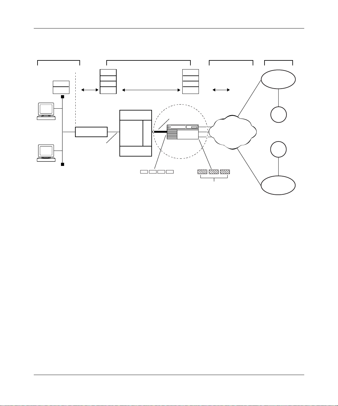
Figure 1-1
shows a sample DSL access network that uses an AHB router. This
network is divided into four separate segments:
• The customer premises, which consist of th e remote host and modem, referred
to as ADSL terminal unit, remote end devices (ATU-R)
• The network provider POP, which consists of DSL access multiplexor ADSL
terminal unit, central devices (DSLAM ATU-C), ATM access network, and
the AHB router
• The public network WAN infrastructure (typically IP over ATM or frame
relay)
• The ISP or corporate network, which provides internet service for remote
CPE stations
1-2
308611-14.00 Rev 00
Page 21
0050
ATM Half-Bridge Overview
Remote
customer premises
IP
802.3
PC1
PC2
IP
802.3
AAL
ATM
ATU-R
ATM
over
DSL
Network provider
central office
DSLAM
ATU-C
M
U
X
DSLAM
1483 encapsulated IP
packets in ATM
IP
802.3
AAL
ATM
OC-3 link
BLN/BCN
router
Frames
Figure 1-1. DSL Network with an AHB (BLN/BCN) Router
WAN
infrastructure
IP
IP
ATM
Frame relay
ISP or
corporate network
ISP1
Corp1
Corp2
ISP2
ATM
A
The following steps explain how IP packets travel from th e CPE host (remote
user) on an Ethernet segment to the AHB router located at the public network
provider’s central office:
1.
2.
3.
308611-14.00 Rev 00
A user (PC or workstation) at a remote site sends Ethernet packets to an
ATU-R attached to a remote Ethernet LAN segment (10 MB).
The ATU-R, acting as an Ethernet/ATM bridge, performs the following tasks:
• Accepts the Ethernet packets
• Segments the Ethernet packets into ATM cells according to RFC 1483
(802.2/LLC bridge encapsulation)
• Transmits the ATM cells to a DSLAM ATU-C at the public network
provider’s site
The ATU-C receives the ATM cells, which are multiplexed along with cells
from other ATU-Cs, and tra nsmits them t o the ATM netw ork o v er one or more
OC-3 links.
1-3
Page 22

Configuring ATM Half-Bridge Services
4.
The ATM network, located at the central office, switches the ATM cells and
forwards them over PVCs to the ATM interface on the AHB (BLN/BCN)
router.
How the AHB Router W orks
AHB combines bridging and I P routin g on the r outer pla tform. On t he DSL access
side, the router receives RFC 1483 encapsulated bridged Ethernet frames
containing IP packets from CPE hosts. On the WAN side, ISP’s and corporate
networks receive routed IP frames. AHB dynamically learns the association
between IP addresses assigned to CPE hosts and the correct RFC 1483 bridged
Ethernet header data for the host.
Forwarding Inbound Packets from CPE Hosts
AHB decapsulates and then routes IP packets it receives from a remote CPE host
to an ISP or corporate network. When AHB receives the incoming packets on its
ATM inte rface, it checks its local b ridge table to determine whether the p acket’s
source IP address corresponds to the host IP address in the associated AHB table
entry. If the bridge table contains the bridge entry, and the entry matches the
bridge information (the correct circuit and VCID), then AHB strips off the RFC
1483 bridged Ethernet header information and forwards the packet using IP
routing to the appropriate ISP’s and corporate networks.
1-4
If AHB does not find the bridge entry in its local bridge table, and you selected
unsecure learning mode, AHB creates a new bridge entry using the packet header
data from the incoming packet. If you selected secure learning mode, AHB
creates a new bridge entry only if this is a new DHCP request (for information
about using unsecure and secure learning mode, see “Dynamically Learning New
Bridge Table Entries”). The AHB router cannot use this bridge entry until it
receiv es a DHCP reply on a non-AHB interf ace that matches the desti nation MAC
address in the bridge ent ry. The IP address is assig ned at this time. If no matching
bridge entry is found for an i ncoming pack et on an AHB interf ace, the pack et may
still be forwarded if either it is a DHCP packet or if you have disabled inbound
packet filtering.
308611-14.00 Rev 00
Page 23

Forwarding Outbound Packets to CPE Hosts
IP packets received from ISPs or corporate networks that are destined for CPE
hosts are sent to AHB b ased on th e AHB rout e in t he IP r outin g tabl e. When AHB
receiv es I P pack et s, it sea rches its loc al bridge t able fo r an asso cia ted bri dge ent ry
based on the packet’s destination IP address. If AHB finds an associated bridge
entry, it adds the RFC 1483 encapsulation and Ethernet header information to the
packet. Then it forwards the packet on the correct outgoing interface and PVC to
reach the remote CPE host.
If AHB does not f ind a n associ ated bri dge entr y for the pack et in its br idge ta ble, it
drops the packet.
Using DHCP to Dynamically Assign IP Addresses
CPE hosts can use DHCP to obtain their IP address and default gateway address.
When you boot the router, the CPE host sends a DHCP request packet, which is
relayed by the DSL modem to the AHB router. The AHB router acts as a DHCP/
BootP relay agent. When the BootP relay agent configured on the ATM service
record receives the DHCP request packet, it fills in the associated IP interface
address (the address you specified for the ATM interface) as the gateway address.
The BootP relay agent then forwards the packet to the DHCP server using either
the BootP forwarding interface method or the BootP preferred server method.
ATM Half-Bridge Overview
When the DHCP server receives the DHCP REQUEST packet, it checks to see
whether the gateway address is filled in. If this address is fille d in, DHCP sends a
reply packet (DHCPACK) to the BootP relay agent on the AHB router. The AHB
router then forw ar ds t he DHCPACK reply to the CPE ho st usi ng th e a sso ciated IP
address of the unnumbered IP interface.
DHCP servers often use the gateway address in the DHCP request to determine
the address pool to use when assigning a client IP address.
The DHCP server may not respond if it receives a DHCP request where the
gateway address is on the same subnet as the DHCP server’s IP address.
Therefore, when selecting an associated IP address for the unnumbered ATM
circuit, choose an add re ss other than the IP a ddr ess of a di re ctl y conn ect ed DHCP
server.
308611-14.00 Rev 00
1-5
Page 24
Configuring ATM Half-Bridge Services
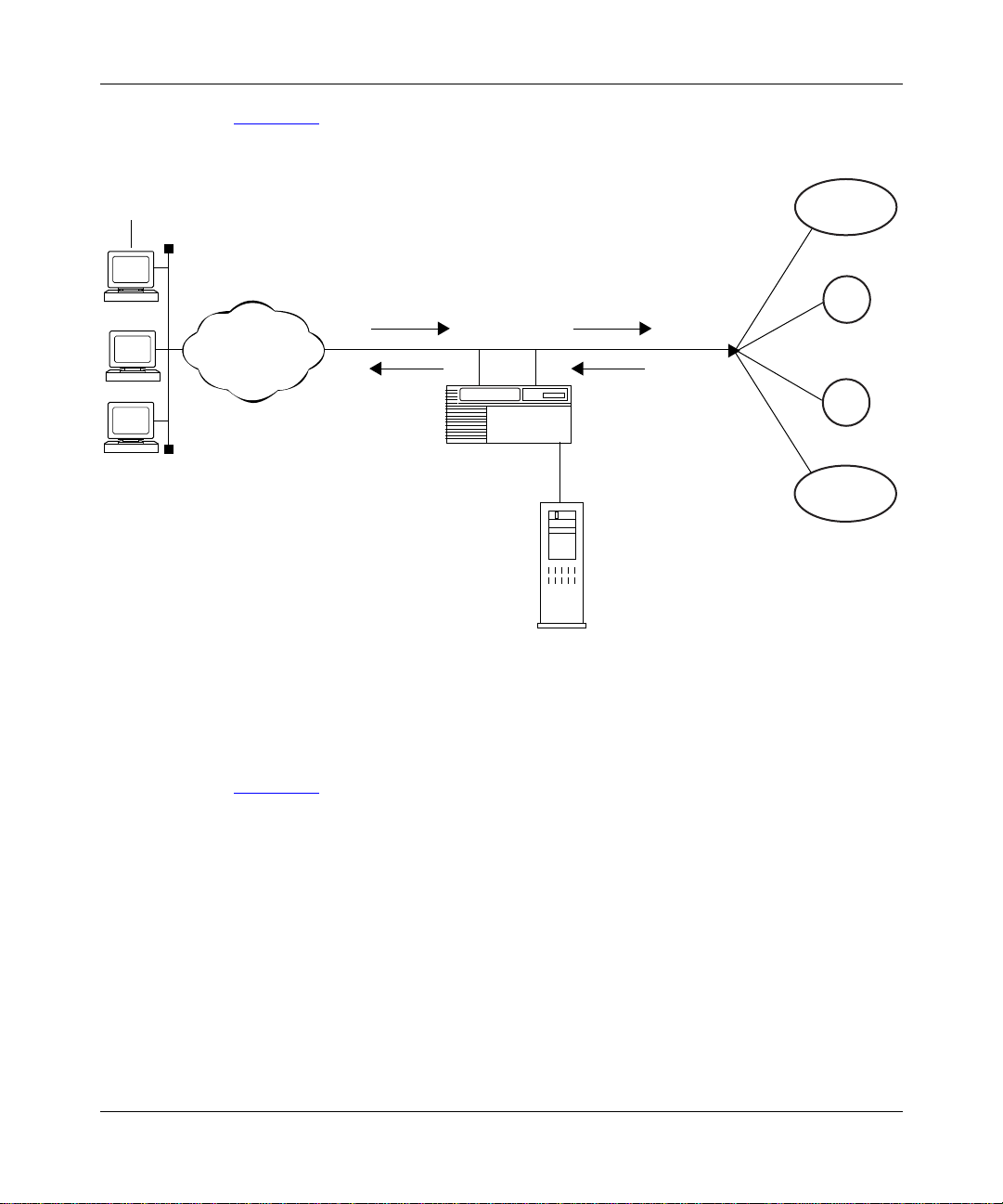
Figure 1-2 shows how the remote hosts identify the DHCP server on the network.
Remote
host
1. Remote host broadcasts
a DHCPDISCOVER
PC1
PC2
PC2
ATM
packet.
4. BootP relay agent
forwards
DHCPOFFER
message to
CPE host.
AHB router
(BootP relay agent)
DHCP
server
Figure 1-2. How CPE Hosts Identify a DCHP Server
2. BootP relay agent transmits
DHCPDISCOVER
packet to DHCP server
that supplied a
DHCPOFFER packet.
3. DHCP server
transmits
DHCPOFFER
message to BootP
relay agent in
AHB router.
ISP1
Corp1
Corp2
ISP2
ATM0053A
1-6
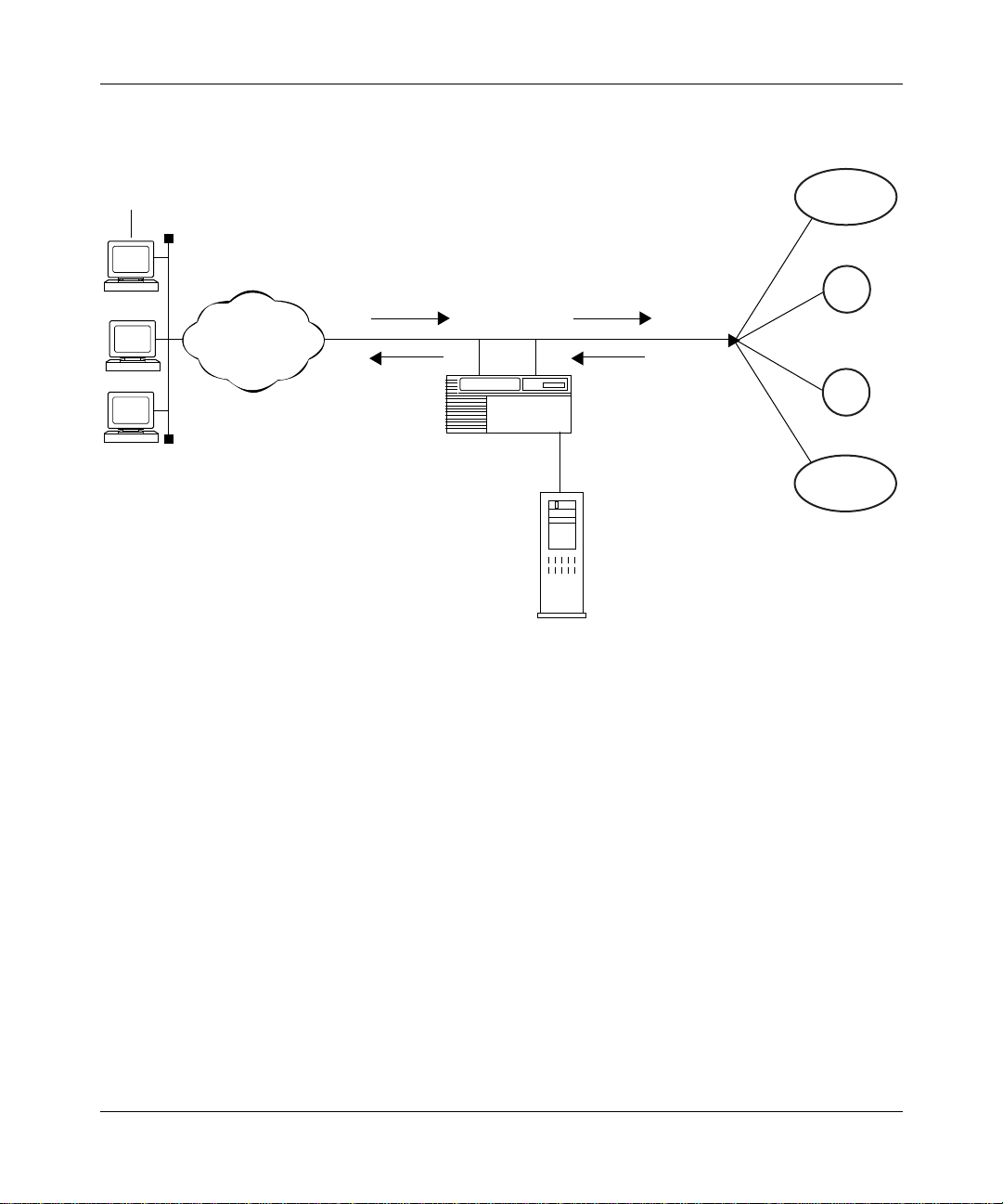
Figure 1-3 shows how the CPE hosts request and receive IP addresses from the
DHCP server.
308611-14.00 Rev 00
Page 25
ATM Half-Bridge Overview
Remote
host
PC1
PC2
PC2
ATM
1. Remote host
broadcasts
DHCPREQUEST
packet.
4. BootP relay agent
agent transmits
DHCPACK
packet or
DHCPNAK
packet to
remote host.
AHB router
(BootP relay agent)
DHCP
server
2. BootP relay
agent forwards
DHCPREQUEST
packet to DHCP
server using the
preferred server
or forwarding
interface method.
3. Target DHCP
server transmits
DHCPACK
packet or
DHCPNAK
packet to BootP
relay agent.
ISP1
Corp1
Corp2
ISP2
ATM0054A
Figure 1-3. How CPE Hosts Request and Receive IP Addresses from the DHCP Server
Dynamically Learning New Bridge Table Entries
The AHB router dynamically learns new bridge entries it receives from CPE
hosts. You can determine the method by which AHB learns these entries by
configuring the auto learning method configuration parameters on the AHB
router. AHB provides the following auto learning methods:
• Unsecure
•Secure
• Both (default)
•None
308611-14.00 Rev 00
1-7
Page 26

Configuring ATM Half-Bridge Services
Unsecure Learning Method
AHB learns new bridge entries from any IP and ARP packets it receives on
ATM/AHB-configured inter faces when you set the auto learn method to unsec ure
or both.
Secure Learning Method
When you set the auto learning met hod to Secure or Both, AHB learns ne w bridge
entries from DHCP replies sent on AHB-configured circuits. Secure entries take
precedence over unsecure entries.
Before you can use secure learning mode, make sure that you:
• Configure BootP on both the unnumbered ATM interface and on the
associated numbered IP interface.
• Configure a BootP preferred server or forwarding interface on the
unnumbered ATM interface (use the circuit number as the IP source address).
• V e rify that the IP ad dress assigne d by the DHCP serv er is on a dif ferent subnet
than the BootP gateway address (that is, the associated numbered IP
interface).
1-8
In secure learning mode, the AHB router serves as a BootP relay agent,
forwarding DHCP requests it receives from CPE hosts.
When you set the learning method to both, AHB learns bridge entries either
securely and unsecurely. When you set the learning method to None, AHB will
not learn new bridge entries.
For information about configuring the auto learn method on an AHB router, see
“Setting the Auto Learn Method”on page 3-2.
308611-14.00 Rev 00
Page 27

Maintaining the AHB Bridge Table
AHB maintains a bridge t able o n each s lot. The tabl e cont ains a lis t of h ost en tries
to or from which the router will forward traffic. These host entries map the IP
address of a CPE host to the following:
• ATM interface on which it is learned on the AHB router
• Virtual Path Identi fier /Virtual Channel Ident ifie r (VPI/VCI) number
• RFC 1483 encapsulation type
• Ethe rnet header information
ATM Half-Bridge Overview
Table 1-1
Table 1-1. Sample AHB Bridge Table
Host ID
200.10.10.1 2 101/31 Bridged Ethernet frame:
shows a sample AHB bridge table.
Outgoing
Circuit VPI/VCI RFC 1483 Bridge Header
src MAC addr= 010203040506
dest MAC adrr= 07080oaaboc
Ethertype= 0800 (IP)
Adding Bridge Table Entries
In unsecure learning mode, AHB adds a new entry to the bridge table whenever it
receives an IP or ARP packet that is not already in the table.
In secure learning mode, AHB adds new entries to its table when it receives
certain incoming and outgoing DHCP messages. AHB adds new table entries
when the CPE host on the remote site s ends a DHCPDI SCOVER message (source
IP address equals 0.0.0.0). This new table entry identifies the incoming port,
VPI/VCI, and RFC 1483 encapsulation data (including source MAC address).
There is no IP address fo r the new table entry at this point.
AHB forwards only certain DHCP packets (ACK or NAK) to the CPE host using
this entry before an IP address is assigned. When AHB receives a DHCPACK
message, it updates the table entry to id entify the cor rect IP addr ess as provi ded by
the DHCP server. When AHB learns the first host entry on a network, it inserts a
route into the IP routing table for that network.
308611-14.00 Rev 00
1-9
Page 28

Configuring ATM Half-Bridge Services
Removing Bridge Table Entries
AHB removes an existing table entry whenever it adds a new entry with the same
source MA C a ddress , ATM port, and VPI/VCI n umber. AHB also removes a ta ble
entry when it receives a DHCPRELEASE message (assuming that the source IP
address-to-ATM port /VPI /VCI ma ppi ng is correct). If the entry b ein g re moved is
on the original sl ot , al l other slots that h ave received copies ar e notified t o r emove
those entries. When AHB removes the last host entry on a network, it deletes the
corresponding route from the IP routing table.
Replacing Bridge Table Entries
If the bridge table contains a bridge entry that was learned on a different circuit/
PVC, and AHB learns another IP packet with the same IP address on a different
circuit and VCID, then AHB replaces the old entry with the new entry. New
entries that AHB learns in unsecure mode do not replace existing entries learned
in secure mode, even if AHB learned them on different slots.
Using Source-Based Routing
The network provider can use source-based routing to ensure that the packet sent
from a CPE ho st travels to the correct ISP gateway first, regardless o f its
destination address. The ISP gateway can be an edge router directly connected to
an AHB router via a WAN interface (frame relay, PPP) or a router located within
the ISP’s domain. This option allows multiple links connecting the AHB router
with the ISP network. If one link or edge router fails, traffic from ATM-attached
hosts is routed via another edge router.
1-10
You use source-based routing by configuring an IP traffic filter on the ATM
interface. You must specify traffi c filter criteria and a traffic filter action. The
traffic filter criteria is the range of source IP add resses allocated to CPE hosts
belonging to a single ISP. You must configure a separate traffic filter for each
range of source addresses that get assigned to the ATM-attached hosts by an ISP.
These filters must be installed on every AHB circuit.
The traffic filter action is “forward to next hop,” wh ich identifies the ISP’s
gateway device. The next-hop address in the traffi c filter need not be a directly
attached host. If it is not a directly attached host, AHB accesses the routing table
to determine the directly attached host to which the packets are sent.
308611-14.00 Rev 00
Page 29

You can use the “forward to next hop” feature to improve reliability. Consider an
example where an ISP home network has two border routers: 200.1.2.3 and
200.3.4.5. If the source-based routing gateway address (next-hop address in the
traffic filter) is advertised by both border routers, t hen the AHB ro uter will send
packets from the ATM-attached hosts to whichever border router has the best
route. If this border router fails or if the link goes down, then the packets are sent
to the alternate border router. The gateway address does not need to belong to a
real device because the ISP border router forwards packets based on the
destination IP address.
For information about configuring IP filters for source-based routing, see
“Configuring Traffic Filters for Source-Based Routing,” on page 3-10.
Responding to Proxy ARP Requests
By default, AHB receives ARP requests from ATM-attached hosts. When the
AHB router receives an ARP request, it responds to this request with its own
hardware address as the target MAC address. You must enable proxy ARP
separately on each circuit.
ATM Half-Bridge Overview
When proxy ARP is enabled, the AHB router responds to ARP requests if all of
the following conditions are true:
• The ARP request receiv ed by AHB is not a self-ARP request (tha t is , the ho st
• The host’s (sender) address is already in the bridge table or can be learned
• The target host address either is in the host table and has a different
For informat ion about conf iguring p roxy ARP, see “Enabling and Disabl ing Proxy
ARP on a Circuit” on page 3-10.
308611-14.00 Rev 00
IP address equals the target IP address or the source address equals 0.0.0.0).
from this packet (unsecure mode enabled).
circuit VPI/VCI, or the target host address is not in the bridge table.
1-11
Page 30

Configuring ATM Half-Bridge Services
Using Inbound Packet Filtering
AHB uses inbound pack et f ilterin g to forw ard b ridge pack ets i t recei v es from CPE
hosts on an AHB interface, regardless of whether an entry exists in the bridge
table for that CPE host. The AHB interface must be an ATM service record
with LLC/SNAP encapsulation. For information about configuring inbound
packet filtering, see “Enabling and Disabling Inbound Packet Filtering” on
page 3-7.
1-12
308611-14.00 Rev 00
Page 31

Chapter 2
Starting AHB Services
This chapter provides instructions for starting AHB services with the default
configuration values supplied by Nortel Networks.
This chapter includes the following information:
Topic Page
Network Planning Considerations 2-1
AHB Configuration Requirements 2-1
Configuring AHB Services 2-5
Configuring a DHCP/BootP Relay Agent 2-10
Network Planning Considerations
Before you configure AHB, ensure that you have the following:
• The VPI/VCI numbers (ATM) used in your network configuration
• The ATM circuit names that you configured
• A minimum of 8 MB of memory on the router for ARE processor modules
AHB Configuration Requirements
Before you can configure AHB on the router, you must:
• Prepare a configuration file.
• Configure an IP interface on the router.
• Configure circuitless IP on the router.
308611-14.00 Rev 00
2-1
Page 32

Configuring ATM Half-Bridge Services
Preparing a Configuration File
To create a configuration file for AHB, complete the following tasks:
You do this System responds
Site Manager Procedure
1. Choose
2. Choose
3. Choose
Dynamic.
4. Select the configuration file and click on
OK
5. Choose either the BLN or BCN router
model and cli ck on
Tools.
Configuration Manager.
Local File, Remote File
.
Confirm
, or
.
The Tools menu opens.
The Configuration Manager window
opens.
Site Manager prompts you for the
configuration file you want to open.
The Configuration Manager window
opens, displaying the router models.
The Module List opens.
If you have ques tions about ho w to perfo rm any of these pre liminary task s, refer to
Configuring and Managing Routers Using Site Manager.
set
The Technician Interface allows you to modify parameters by issuing
commit
commands with the managemen t inf ormati on base (MIB) obj ect I D. This
and
process is equivalent to modifying parameters using Site Manager.
For more information about using the Technician Interface to access the MIB,
refer to Using Technician Interface Software.
Caution:
Nortel Networks strongly recommends that you use the Technician
Interface f or very minor MIB ad jus tments only. The Tech nic ia n In te rface does
not validate parameter entries. Entering an invalid value can corrupt your
configuration.
2-2
Proceed to the next section to configure an IP interface on the router.
308611-14.00 Rev 00
Page 33

Configuring an IP Interface on the Router
You must configure an IP interface on a non-ATM/AHB interface. This can be a
LAN interface or a frame relay interface. You use this IP interface address as the
associated IP interface when defining the unnumbered IP circuit for the AHB
router.
To configure an IP interface on the router, begin at the Module List window and
complete the following tasks:
Site Manager Procedure
You do this System responds
Starting AHB Services
1. In the Module List, choose a
(for example, Quad Ethernet).
2. Click on a
example, XCVR1).
3. Supply a
default circuit name) and click on OK.
4. Select IP, then click on OK. The IP Configuration window opens.
5. Specify a valid IP address in
dotted-decimal no tation f or the
parameter (for example, 1.1.1.1).
Click on
description on page A-15.
6. Accept the default values for the follow ing
parameters:
•
•
•
Click on
descriptions on page A-15.
7. Click on OK. You return to the Configuration Manager
link module connector
circuit name
or see the parameter
Help
Subnet Mask
Transmit Bcast Addr
UnNumbered Assoc Address
or see the parameter
Help
link module
(or accept the
IP address
(for
The Add Circuit List window opens.
The Select Protocols window opens.
window.
308611-14.00 Rev 00
2-3
Page 34

Configuring ATM Half-Bridge Services
Configuring Circuitless IP on the Router
To operate AHB, you must configure unnumbered IP interfaces on the router and
assign an associated IP address to each interface. You can elect to use the
circuitless IP address as the associated address for unnumbered interfaces.
AHB uses unnumbered interfaces because not all hosts attached via the ATM
circuit are on the same I P networ k. Furthermor e, a host may cha nge its IP ne twork
over time (due to subscribing with different service providers), and it would be
inconvenient to move the PVC for that host each time its network IP address
changes.
When you configure a circuitless IP interface, note the following:
• You can configure only one circuitless IP interface per router.
• You must assign a unique IP address and subnetw ork number t o the cir cuitless
IP interface.
A circuitless IP interface has an IP address that is not mapped to the address of a
specific circuit. Thus, if one or more of the router’s IP interfaces becomes
disabled, this circuitless feature ensures that the router is always reachable using
the circuitless interface address, as long as a viable path to the router exists.
2-4
For more information about circuitless interfaces, see Configuring IP, ARP, RARP,
RIP, and OSPF Services.
To configure a circuitless IP interface on the router, begin at the Configuration
Manager wind ow and complete the following tasks:
Site Manager Procedure
You do this System responds
1. In the Configuration Manager window,
choose
2. Choose
3. Choose
4. Choose
Protocols
. The IP menu opens.
IP
Circuitless IP
Create
.
. The Circuitless IP menu opens.
. The IP Configuration window opens.
The Protocols menu opens.
(continued)
308611-14.00 Rev 00
Page 35

Starting AHB Services
Site Manager Procedure
You do this System responds
5. Specify a unique IP address in
dotted-decimal no tation f or the
parameter (for example, 250.225.2.2).
Click on
description on page A-15.
6. Specify a valid subnet mask for the
Subnet Mask
255.255.255.0).
Click on
description on page A-15.
7. Click on OK. Site Manager saves the circuitless IP
or see the parameter
Help
parameter (for example,
or see the parameter
Help
IP address
(continued)
interface, and opens a special Select
Protocols window that lists the protocols
that you can configure on a circuitless
interface.
Go to the next section to configure AHB services on the router.
Configuring AHB Services
Configuring AHB services involves:
• Creating an ATM interface
• Adding an LLC/SNAP service record for PVCs
• Adding AHB on an LLC/SNAP service record
• Adding PVCs to the LLC/SNAP service record on an ATM interface
• Configuring a BootP relay agent
Before configuring AHB, refer to Configuring and Managing Routers with Site
Manager for instructions about the Site Manager configuration tool and how to
work with configuration files.
308611-14.00 Rev 00
2-5
Page 36

Configuring ATM Half-Bridge Services
Creating an ATM Interface
To create an ATM interface, complete the following tasks:
You do this System responds
Site Manager Procedure
1. In the M odule Li st, cho ose an
module
2. Click on an
(labeled ATM1).
3. Supply a circuit name (or accept the
default circuit name) and click on OK.
4. Change the
parameter to
Click on
description on page A-19.
You disable ATM signaling because AHB
runs only on PVCs, not SVCs.
5. Click on OK. The Edit ATM Connector window opens.
(for example, ARE OC-3 MM).
ATM link module connector
Enable ATM Signaling
Disable
Help
.
or see the parameter
ARE ILI link
Go to the next section to add an LLC/SNAP service record to the ATM interface
that you just created.
Adding an LLC/SNAP PVC Service Record
When you add a service record to an ATM interface, you must specify the data
encapsulation type and virtual connection it uses. AHB requires that you add the
LLC/SNAP data encapsulat ion type an d the circu it (PVC) conne ction type for this
service record.
The Add Circuit window opens.
The Initial ATM Signaling Config window
opens.
Site Manager changes the value of this
parameter.
2-6
Caution:
You cannot edit the Data Encapsulation Type or Virtual Connection
Type parameter once you assign it to a service record. However, you can edit
the Data Encapsulation Type for individual PVCs.
For an expl anation of the dif ferent data encapsula tion types and rul es for assigni ng
data encapsulation, refer to Configuring ATM Services.
308611-14.00 Rev 00
Page 37

Starting AHB Services
To add an LLC/SNAP service record, complete the following tasks:
Site Manager Procedure
You do this System responds
1. In the Edit ATM Connector window, click
on
Service Attributes
2. Click on
3. Click on
Add.
OK.
.
The ATM Service Records List window
opens.
The ATM Service Record Parameters
window opens, displaying default values
for the Data Encapsul atio n type and
Virtual Connector type.
Because you disabled ATM signaling
when you created the circuit, the ATM
Service Record Parameters window
automatically changes the default for the
Data Encapsulation Type parameter to
Logical Link Control/Subnetwork Access
Protocol (LLC/SNAP) and the Virtual
Connection Type parameter to PVC.
The ATM service information appears in
the ATM Service Record List and the
Select Protocols window opens.
Go to the next section, “Adding AHB to the LLC/SNAP Service Record
Adding AHB to the LLC/SNAP Service Record
When adding AHB services to an LLC/SNAP service record, remember the
following:
.”
• A PVC type service record requires that you add at least one PVC for the
• Each service record globally controls all protocols for any PVCs that it
308611-14.00 Rev 00
service record to operate.
contains.
2-7
Page 38

Configuring ATM Half-Bridge Services
To add AHB to an L LC/SNAP service record, complete the following tasks:
You do this System responds
Site Manager Procedure
1. In the Select Protocols window, click on
AHB.
2. Click on
3. Specify an unnumbered interface address
(0.0.0.0) for the
Click on
description on page A-15.
4. Specify the associate d numbered circuit
address for the
Address
circuitless IP interface address.
Click on
description on page A-16.
5. Click on OK. The ATM Half-Bridge Configuration
6. Accept the AHB default configurat ion
values and click on OK.
OK.
IP Address
or see the parameter
Help
UnNumbered Assoc
parameter. This may be a
or see the parameter
Help
parameter.
The Configurati on Manager auto matically
highlights IP and BootP, add ing these
protocols to the service record.
The IP Configuration window opens,
prompting you to specify IP configuration
parameters.
window opens.
The ATM Virtual Channel Link window
opens.
2-8
Next, add PVCs to the LLC/SNAP service record on the ATM interface.
308611-14.00 Rev 00
Page 39

Adding PVCs to the LLC/SNAP PVC Service Record
T o add PVCs to the LLC/SNAP service record on the ATM interface, complete the
following tasks:
Site Manager Procedure
You do this System responds
Starting AHB Services
1. In the ATM Virtual Channel Link window,
click on
2. Supply the following information:
•A
the cell header, identifies the virtual
path of the PVC. The header can
contain a maximum of 8 VPI bits for a
UNI connection. This bit range allows
for path identifiers from 0 to 255.
•A
the cell header, identifies the virtual
channel of the PVC. The header can
contain a maximum of 16 VCI bits.
This bit range allows for channel
identifiers from 0 to 65535.
Click on
descriptions on page A-23.
3. Click on OK. The ATM Virtual Channel Link window
4. To add another PVC with the default
configuration, repe at ste ps 1 through 3.
5. Click on
6. Click on
7. Click on
.
Add
This number, which is part of
.
VPI
This number, which is part of
.
VCI
or see the parameter
Help
. The ATM Service Records List window
Done
. The Edit ATM Connector window opens.
Done
. You return to the Configuration Manager
Done
The ATM Virtual Channel Link
Parameters window opens.
opens. For information about changing
parameters in the ATM Virtual Channel
Link window, refer to
opens.
window.
Appendix B.
308611-14.00 Rev 00
2-9
Page 40

Configuring ATM Half-Bridge Services
Note:
Following the recommendation of the ATM Forum, virtual channel
identifiers from 0 to 31 are reserved for signaling and added functionality.
Next, you must configure BootP to def ine a forwarding path between a router and
a BootP/DHCP server on the network.
Configuring a DHCP/BootP Relay Agent
To allow the AHB router to successfully forward DHCP packets from CPE hosts
to a DHCP server on the networ k, you must conf igure a Boot P relay agent on both
the unnumbered ATM/IP interface and an associated numbered interface. AHB
does this automatically when you add AHB to the ATM service record. You also
must define a forw ardi ng path bet ween the AHB router and a DHCP ser v er on the
network. You establish this forwarding path using one or both of the following
methods:
• Configure one or more BootP forwarding IP interfaces on the router.
You define one IP interface to receive DHCP request pac k et s f ro m t he r emot e
CPE hosts and another to transmit (broadcast) DHCP request packets to the
DHCP server.
• Configure one or more BootP preferred se rver s on an IP interf ace on the AHB
router .
You define one IP interface to receive DHCP request pac k et s f ro m t he r emot e
CPE hosts and to then unicast the requests directly to the DHCP server.
Creating a BootP Relay Agent Forwarding Interfaces
You create a BootP relay agent forwarding table for the IP interfaces that you
configure to receive the incoming DHCP request packets and to forward the
outgoing DHCP request packets to the DHCP server on the network. The BootP
relay agent forwards DHCP request packets based on the IP addresses of the
interfaces in this table. For more information about configuring a forwarding
table, refer to Configuring SNMP, BootP, and DHCP Services.
2-10
308611-14.00 Rev 00
Page 41

Starting AHB Services
Site Manager req uires tha t you speci fy input and out put addres ses to conf igure th e
BootP relay agent on the AHB router. The input IP address is the ATM
unnumbered interface on which the DHC P request packet is received. The ATM
unnumbered interfa ce address appe ars in the BootP Rel ay Agent table. I ts last four
digits are 0.0.0 <cir c uit_number >, wher e circuit number is the unnumbered cir cuit
that you configured.
The output IP address is the address of the local IP interface to which the DHCP
packets are forwarded.
To create a BootP relay agent forwarding table, complete the following tasks:
Site Manager Procedure
You do this System responds
1. In the Configuration Manager window,
choose
2. Choose IP. The IP menu opens.
3. Choose
4. Choose
5. Click on
6. Click on
7. Add a BootP forwarding entry by setting
the following parameters:
• Input IP Address
• Output IP Address
Click on
descriptions on page A-11.
8. Click on OK. The BOOTP Relay Agent Forwarding
9. Click on
10. Click on
Protocols
BootP
Relay Agent Interface Table
Forward I/F
Add
or see the parameter
Help
Done
Done
.
. The BOOTP menu opens.
. The BOOTP Relay Agent Forwarding
. The BOOTP Addresses window opens.
. The BOOTP Relay Agent Interface Table
. You return to the Configuration Manager
The Protocols menu opens.
. The BOOTP Relay Agent Interface Table
window opens, displaying the IP
interfaces that you configured on the AHB
router (ATM PVCs, circuitless IP
interface, and so forth).
Table window opens.
Table window opens.
window opens.
window.
308611-14.00 Rev 00
2-11
Page 42

Configuring ATM Half-Bridge Services
Configuring BootP Preferred Servers
You can configure a BootP preferred server by specifying the IP address of the
relay agent on the router and the IP address of the target server. You configure a
preferred server when you know the IP address of the DHCP server to which you
want to send a DHCP request.
Specifying the Relay Agent IP Address
The relay agent I P address is the inter f ace that you want to receive DHCP packets
from a CPE host. If you configured BootP on an unnumbered interface
(ATM/AHB interface), specify the associated numbered interface address for the
relay agen t IP address.
To specify the relay agent IP address, complete the following ta sks:
Site Manager Procedure
You do this System responds
1. In the Configuration Manager window,
choose
2. Choose IP. The IP menu opens.
3. Choose
4. Choose
5. Click on
6. Click on
7. Set the
parameter. Click on
parameter description on page A-14.
8. Click on OK.
9. Click on
Protocols
BOOTP
Relay Agent Interface Table
Pref Serv
Add
Relay Agent IP Address
Done
.
. The BOOTP menu opens.
. The BOOTP Relay Agent Preferred
. The BOOTP Preferred Server
or see the
Help
. You return to the Configuration Manager
The Protocols menu opens.
. The BOOTP Relay Agent Interface Table
window opens.
Server Table opens.
Configuration window opens.
window.
2-12
308611-14.00 Rev 00
Page 43

Starting AHB Services
Specifying the Target Server IP Address
After you specify the relay agent IP address, you must specify the IP address of
the DHCP server that should receive the DHCP packet from the BootP relay
agent.
To specify the target server IP address, complete the following tasks
Site Manager Procedure
You do this System responds
1. In the Configuration Manager window,
choose
2. Choose IP. The IP menu opens.
3. Choose
4. Choose
5. Click on
6. Click on
7. Set the
on
on page A-15.
8. Click on OK.
9. Click on
Protocols
BOOTP
Relay Agent Interface Table
Pref Serv
Add
Target IP Server
or see the parameter description
Help
Done
.
. The BOOTP menu opens.
. The BOOTP Relay Agent Preferred
. The BOOTP Preferred Server
parameter. Click
. You return to the Configuration Manager
The Protocols menu opens.
. The BOOTP Relay Agent Interface Table
window opens.
Server Table opens.
Configuration window opens.
window.
:
308611-14.00 Rev 00
2-13
Page 44

Page 45

Chapter 3
Customizing AHB Services
When you first configure AHB services, default values are in effect for all
parameters (see parameter descriptions in Appendix A). You may want to change
these values, depending on the requirements of your network.
This chapter provides information about how to customize AHB to use it
effectively on your network. This chapter includes the following topics:
Topic Page
Modifying the AHB Configuration 3-1
Modifying AHB Circuits 3-8
Configuring Traffic Filters for Source-Based Routing 3-10
Deleting AHB from the Router 3-11
Modifying the AHB Configura tion
To change the way AHB operates on the router, you can modify the AHB global
parameters in the Edit ATM Half-Bridge Global Parameters window (see Figure
A-1 on page A-2).
Enabling and Disabling AHB
By default, AHB forwards packets to and from ATM PVCs when you enable the
AHB function on the router. When you disable AHB, you prevent AHB from
forwarding packets to and from ATM PVCs.
308611-14.00 Rev 00
3-1
Page 46

Configuring ATM Half-Bridge Services
To enable and disable AHB forwarding on the router, complete the following
tasks:
You do this System responds
Site Manager Procedure
1. In the Configuration Manager window,
choose
2. Choose
3. Choose
4. Choose
5. Set the
or see the parameter description in
Appendix A.
Protocols
. The IP menu opens.
IP
AHB
Global
Enable
.
. The AHB menu opens.
. The Edit ATM Half-Bridge Global
parameter. Click on Help
Setting the Auto Learn Method
You can determine the method by which AHB automatically learns new bridge
entries on the router by configuring the auto learning method. You can configure
AHB in one of the following learning modes:
•Secure
• Unsecure
•Both
•None
The Protocols menu opens.
Parameters window opens.
3-2
By default, the auto learn method is set to Both. This means that AHB will learn
new bridge entries either securely or unsecurely.
If you set the learning mode to Secure or Both, AHB learns new bridge entries
from the DHCP reply packets sent on the AHB-configured interface. Entries
learned in secure mode always take precedence over entries learned in unsecure
mode.
If you set the learning mode to Unsecure or Both, AHB learns new bridge entries
from IP and ARP packets received on the AHB-configured interface.
308611-14.00 Rev 00
Page 47

Customizing AHB Services
To set the auto learn method by which AHB learns bridge entries, complete the
following tasks:
Site Manager Procedure
You do this System responds
1. In the Configuration Manager window,
choose
2. Choose
3. Choose
4. Choose
5. Set the
Click on
description on page A-3.
6. Click on
Protocols
. The IP menu opens.
IP
AHB
Global
Auto Learn Method
Help
OK.
.
. The AHB menu opens.
. The Edit ATM Half-Bridge Global
or see the parameter
Configuring a Local AHB Init File
AHB Init files are ASCII data files that you can use to manually add bridge table
entries and or configure PVCs on an AHB interface. You create the init files
locally, but must store them on the rou ter’s flash memory card. AHB reads the i nit
files from the router’s flash memory when the router boots.
The AHB init files contain an extra flag on each entry that indicates where AHB
should create the corresponding PVC identified in the bridge entry, if it does not
already exist.
The Protocols menu opens.
Parameters window opens.
parameter.
You return to the Configuration Manager
window.
Sample Init File
In the AHB init file, there is a section for each router slot that has configured
bridge entries. Slots that do not contai n hosts do not need a se ction he ader. Within
a section, there is one line for each bridge entry.
308611-14.00 Rev 00
3-3
Page 48

Configuring ATM Half-Bridge Services
A sample init file (a hb.dat) follows:
[SLOT 3]
1.3.1.32 255.255.255.0 4 409600 0 0
aaaa030080c200070000112233445566aabbccdde eff0800
1.3.2.32 255.255.255.0 4 409600 0 0
aaaa030080c200070000778899001122aabbccdde eff0800
[SLOT 4]
1.4.2.32 255.255.255.0 5 409600 0 0
aaaa030080c200070000998877665544aabbccdde eff0800
The bridge entry fields (separated by spaces) are:
• Field 1 = host IP address (dotted-decimal)
• Field 2 = host subnet mask (dotted-decimal)
• Field 3 = ATM circu it number (dec imal)
• Field 4 = PVC VPI/VCI (decimal, VPI in bits 0-11, VCI in bits 12-23)
• Field 5 = reference VPI/VCI (decimal)
• Field 6 = host flag s (decimal, bit field)
3-4
• Field 7 = bridge header (hex, 1483 SNAP/LLC + ethernet header)
The host flag bits which can be configured are:
• Bit 0 = no protocol address, do not add bridge entry to table
• Bit 3 = add new PVC (VPI/VCI in field 4) based on reference PVC
• Bit 4 = do not forward packets that match this IP address
• Bit 7 = if set, indi cates that host entry sho uld be deleted
The bridge header has the following format:
• Octets 00-09 = encapsulate for 1483 bridged Ethernet packet
• Octets 10-15 = destination MAC address
• Octets 16-21 = source MAC address
• Octets 22-23 = protocol ID (0x800 for IP)
The reference VPI/VCI identifies a preconfigured ATM PVC whose parameters
are used as a template when AHB creates a new PVC.
308611-14.00 Rev 00
Page 49

Customizing AHB Services
To specify the name of the local init file you want to use, complete the following
tasks:
Site Manager Procedure
You do this System responds
1. In the Configuration Manager window,
choose
2. Choose
3. Choose
4. Choose
5. Set the
or see the parameter description on
Help
page A-4.
6. Click on
Protocols
. The IP menu opens.
IP
AHB
Global
Local Init File
OK
.
. The AHB menu opens.
. The Edit ATM Half-Bridge Global
parameter. Click on
. You return to the Configuration Manager
Specifying an Alternate Init File
You can create an alternate init file (backup) as a safeguard in case the local init
file f ails t o load pr operl y when the r out er boot s. You should co py th e alte rna te ini t
file to a different flash memory card on the AHB router.
When you boot the AHB router, it attempts to read the local init file. If the local
init file is null, or if AHB cannot read the file, it then reads the alternate init file.
The Protocols menu opens.
Parameters window opens.
window.
308611-14.00 Rev 00
3-5
Page 50

Configuring ATM Half-Bridge Services
To specify the name of the alternate init file you want to use, complete the
following tasks:
You do this System responds
Site Manager Procedure
1. In the Configuration Manager window,
choose
2. Choose
3. Choose
4. Choose
5. Set the
Click on
description on page A-4.
6. Click on
Protocols
. The IP menu opens.
IP
. The AHB menu opens.
AHB
. The Edit ATM Half-Bridge Global
Global
Alternate Init File
or see the parameter
Help
. You return to the Configuration Manager
OK
Specifying the Debug Level
You can display the le v el of de b ug messag ing you want the AHB rout er to di splay
in its log file by spec ifying a value for the Debug Level parameter.
By default, the debug level is set to 0, meaning that AHB disables all debug
messages. You can specify a debug level value from 1 to 5. Specifying a higher
value causes AHB to display more detailed debug messages.
To specify the debug level, complete the following tasks:
The Protocols menu opens.
.
Parameters window opens.
parameter.
window.
3-6
Site Manager Procedure
You do this System responds
1. In the Configuration Manager window,
choose
2. Choose
3. Choose
4. Choose
Protocols
. The IP menu opens.
IP
AHB
Global
.
. The AHB menu opens.
. The Edit ATM Half-Bridge Global
The Protocols menu opens.
Parameters window opens.
(continued)
308611-14.00 Rev 00
Page 51

Customizing AHB Services
Site Manager Procedure
You do this System responds
5. Set the
or see the parameter description on
Help
page A-4.
6. Click on
Debug Level
. You return to the Configuration Manager
OK
parameter. Click on
(continued)
window.
Enabling and Disabling Inbound Packet Filtering
By default, inbound packet filtering is disabled on the AHB router. This means
that AHB forwards bridge packets it receives from CPE hosts, regardless of
whether a table entry exists in the bridge table for that host.
When you enable inbound packet filtering on the AHB router, AHB verifies that
the source address in the IP packet is contained in the bridge table and that it
corresponds to the circuit and virtual connection identification number (VCID)
contained in the AHB bridge table. This is a check to ensure that the packets
received by the AHB router are valid.
To enable and disable inbound packet filtering on the AHB router, complete the
following tasks:
You do this System responds
1. In the Configuration Manager window,
2. Choose
3. Choose
4. Choose
5. Set the
6. Click on
308611-14.00 Rev 00
Site Manager Procedure
choose
parameter. Click on
parameter description on page A-5.
Protocols
. The IP menu opens.
IP
AHB
Global
Inbound Packet Filtering
OK
.
. The AHB menu opens.
. The Edit ATM Half-Bridge Global
or see the
Help
. You return to the Configuration Manager
The Protocols menu opens.
Parameters window opens.
window.
3-7
Page 52

Configuring ATM Half-Bridge Services
Modifying AH B Circuit s
You can modify AHB circuits by changing the AHB circuit parameters located in
the ATM Half-Bridge Circuit List window (refer to Appendix A). You may need
to modify AHB circuit characteristics after you configure multiple PVCs on an
ATM interface, and you have configured AHB on this interfa ce. These paramet ers
include:
• Enable
• Learned Host Subnet Mask
• Enabling Proxy ARP
Enabling and Disabling an AHB Circuit
You enable the bridging of packets on an AHB circuit when you configure AHB
interfaces on the router. To disable the bridging of packets on AHB interfaces, set
the Enable parameter to Disable.
To enable and disable the bridging of packets on an AHB circuit, complete the
following tasks:
3-8
Site Manager Procedure
You do this System responds
1. In the Configuration Manager window,
choose
2. Choose
3. Choose
4. Choose
5. Set the
or see the parameter description on
page A-6.
6. Click on
7. Click on
Protocols
. The IP menu opens.
IP
AHB
Circuit List
Enable
Apply
Done
.
. The AHB menu opens.
. The Edit ATM Half-Bridge Circuit List
parameter. Click on
.
. You return to the Configuration Manager
Help
The Protocols menu opens.
window opens.
window.
308611-14.00 Rev 00
Page 53

Specifying the Subnet Mask for the Learned Host
If you set the learning method on the ATM interface to Unsecure or Both, you
must specify a subnet mask for a dynamically learned host. AHB uses the subnet
mask to identify th e host’ s network and to add r outes to the IP routing table based
on the host’s IP address.
If you specify 0.0.0.0 (default) as the subnet mask for learned hosts, then AHB
uses the natural class (A, B, C) subnet mask.
To specify the subnet mask for the learned host, complete the following tasks:
Site Manager Procedure
You do this System responds
Customizing AHB Services
1. In the Configuration Manager window,
choose
2. Choose
3. Choose
4. Choose
5. Set the
parameter. Click on
parameter description on page A-7.
6. Click on
7. Click on
Protocols
. The IP menu opens.
IP
AHB
Circuit List
Learned Host Subnet Mask
Apply
Done
.
. The AHB menu opens.
. The Edit ATM Half-Bridge Circuit List
or see the
Help
.
. You return to the Configuration Manager
The Protocols menu opens.
window opens.
window.
308611-14.00 Rev 00
3-9
Page 54

Configuring ATM Half-Bridge Services
Enabling and Disabling Proxy ARP on a Circuit
By default, proxy ARP i s e nabl ed on the AHB circuit when you co nfigure it. This
tells the AHB router to respond to ARP requests from ATM-atta ched hosts with its
own hardware address as the target MAC address.
You must separately enable or disable proxy ARP on each AHB circuit on the
router.
To enable and disable proxy ARP on each AHB circuit, complete the following
tasks:
Site Manager Procedure
You do this System responds
1. In the Configuration Manager window,
choose
2. Choose
3. Choose
4. Choose
5. Set the
Click on
description on page A-7.
6. Click on
7. Click on
Protocols
. The IP menu opens.
IP
AHB
Circuit List.
Enable Proxy ARP
Help
Apply
Done
.
. The AHB menu opens.
parameter.
or see the parameter
.
. You return to the Configuration Manager
The Protocols menu opens.
The Edit ATM Half-Bridge Circuit List
window opens.
window.
Configuring Traffic Filters for Source-Based Routing
The AHB router may use source-based routing to ensure that packets sent from a
CPE host travel to the correct ISP gateway first, regardless of its destination
address. The ISP gateway can be an edge router directly connected to an AHB
router via a WAN interface (frame relay, PPP) or a router located within the ISP
domain.
You configure source-based routing by creating an IP traffic filter whose action is
“forward to next hop.” You must specify the ISP gateway address (or a virtual
address within the ISP domain) as the next-hop address.
3-10
308611-14.00 Rev 00
Page 55

For detailed information about creating traffic filters for source-based routing,
refer to Configuring Traffic Filters and Protocol Prioritization.
Deleting AHB from the Router
To delete AHB from the router, complete the following tasks:
Site Manager Procedure
You do this System responds
Customizing AHB Services
1. In the Configuration Manager window,
choose
2. Choose
3. Choose
4. Choose
Protocols
. The IP menu opens.
IP
AHB
Delete AHB
.
. The AHB menu opens.
. You return to the Configuration Manager
The Protocols menu opens.
window.
308611-14.00 Rev 00
3-11
Page 56

Page 57

Appendix A
AHB, BootP/DHCP, IP, and ATM
Parameter Descriptions
This appendix contains reference information about customizing AHB global
configuration and AHB circuit parameters. It also contains a subset of parameter
descriptions for BootP/DHCP, IP, and ATM that you can use to configure AHB.
Topic Page
AHB Global Parameters A-2
AHB Circuit Parameters A-6
BootP Relay Agent Interface Table Parameters A-8
BootP Address Parameters A-10
BootP Relay Agent Preferred Server Table Parameters A-12
BootP Preferred Server Configuration Parameters A-14
IP Configuration Parameters A-15
ATM Interface Parameter Descriptions A-17
ATM Service Record Parameter Descriptions A-19
ATM Virtual Channel Lin k Parameter Descrip tions A-23
For each parameter, this appendix provides the following information:
• Parameter name
• Configuration Manager menu path
• Default setting
• Valid parameter options
• Parameter function
308611-14.00 Rev 00
A-1
Page 58

Configuring ATM Half-Bridge Services
• Instructions for setting the parameter
• Management information base (MIB) object ID
The Technician Interface allows you to modify parameters by issuing
commit commands with the MIB object ID. This process is equivalent to
modifying parameters using Site Manager. For more information about using the
Technician Interface to access the MIB, refer to Using Technician Interface
Software.
Caution:
The Technician Interface does not verify the validity of your
parameter values. Entering an invalid value can corrupt your configuration.
AHB Global Parameters
Use the following guidelines to configure AHB global parameters in the Edit
ATM Half-Bridge Global Parameters window (Figure A-1
Half-Bridge Global Parameters window contains parameters that allow you to
customize AHB operation.
set and
). The Edit ATM
A-2
Figure A-1. Edit ATM Half-Bridge Global Parameters Window
308611-14.00 Rev 00
Page 59

AHB, BootP/DHCP, IP, and ATM Parameter Descriptions
The AHB global parameter descriptions follow.
Parameter: Enable
Path: Configuration Manager > Protocols > IP > AHB > Global
Default: Enabled
Options: Enable
Function: Enables or disables AHB packet forwarding to and from ATM PVCs.
Instructions: Select Disable to disable AHB on this interface without deleting it. Select
Enable to reenable AHB services if you previously disabled it.
MIB Object ID: 1.3.6.1.4.1.18.3.5.9.13.1 #2
Parameter: Auto Learn Method
Path: Configuration Manager > Protocols > IP > AHB > Global
Default: None
Options: Secure
Function: Specifies the method by which AHB dynamically learns new bridge entries on
the router.
Instructions: By default, the au to learn metho d is set to Both. This means t hat AHB will learn
new bridge entries either securely or unsecurely.
Disabled
|
Unsecure | Both | None
|
If you set the learning mode to Secure or Both, AHB learns new bridge entries
from the DHCP reply packets sent on the AHB-configured interface. Entries
learned in secur e mode always take precedence over entries learned in unsecure
mode.
If you set the learning mode to Unsecure or Both, AHB learns new bridge
entries from IP and ARP packets received on the AHB-configured interface.
MIB Object ID: 1.3.6.1.4.1.18.3.5.9.13.1 #3
308611-14.00 Rev 00
A-3
Page 60

Configuring ATM Half-Bridge Services
Parameter: Local Init F ile
Path: Configuration Manager > Protocols > IP > AHB > Global
Default: None
Options: None
Function: Specifies a local ASCII data file into w hich you can ad d bridge table entries for
configuring PVCs on an AHB interface. You create init files locally, but you
must store them on the router’s flash memory card. AHB loads the init files
when the router boots.
Instructions: Specify the name of the init file you want to use. Be sure to copy the file to the
router’s flash memory so the router can boot with this file.
MIB Object ID: 1.3.6.1.4.1.18.3.5.9.13.1 #4
Parameter: Alternate Init File
Path: Configuration Manager > Protocols > IP > AHB > Global
Default: None
Options: None
Function: Specifies an alternate init file (backup) as a safeguard in case the local init file
fails to load properly when the router boots.
Instructions: Specify the alternate init file name.
MIB Object ID: 1.3.6.1.4.1.18.3.5.9.13.1 #5
Parameter: Debug Level
Path: Configuration Manager > Protocols > IP > AHB > Global
Default: 0
Options: Recommended values are from 1 to 5
Function: Specifies the level of debug messaging you want to display in the log file for
AHB.
Instructions: Enter the debug messaging level you want.
MIB Object ID: 1.3.6.1.4.1.18.3.5.9.13.1 #6
A-4
308611-14.00 Rev 00
Page 61

AHB, BootP/DHCP, IP, and ATM Parameter Descriptions
Parameter: Inbound Packet Filtering
Path: Configuration Manager > Protocols > IP > AHB > Global
Default: Disabled
Options: Enabled
Disabled
|
Function: By default, inbound packet filtering is disabled on the AHB router. This means
that AHB forwards bridge packets it receives from CPE hosts, regardless of
whether a table entry exists in the bridge table for that host.
When you enable inbound packe t fi lterin g on the AHB router, AHB verifies that
the source address in the IP packet is contained in the bridge table and that it
corresponds to the circuit and virtual connection identification number (VCID)
contained in the AHB bridge table. This is a check to ensure that the packets
received by the AHB router are valid.
Instructions: Choose Enable to enable packet fi ltering on the AHB router. Choose Disable to
disable packet filtering on the AHB router.
MIB Object ID: 1.3.6.1.4.1.18.3.5.9.13.1 #7
308611-14.00 Rev 00
A-5
Page 62

Configuring ATM Half-Bridge Services
AHB Circuit Para meters
Use the following guidelines to configure AHB Circuit parameters in the ATM
Half-Bridge Circuit List window (Figure A -2
).
Figure A-2. ATM Half-Bridge Circuit List
The AHB circuit list parameters follow.
Parameter: Enable
Path: Configuration Manager > Protocols > IP > AHB > Circuit List
Default: Enabled
Options: Enabled
Function: Enables or disables AHB packet forwarding to and from CPE hosts connected
via this circuit.
Instructions: Choose Enable to enable AHB packet forwarding on this circuit. Choose
Disable to disable packet forwarding on this AHB circuit.
MIB Object ID: 1.3.6.1.4.1.18.3.5.9.13.2.1 #2
A-6
Disabled
|
308611-14.00 Rev 00
Page 63

AHB, BootP/DHCP, IP, and ATM Parameter Descriptions
Parameter: Learned Host Subnet Mask
Path: Configuration Manager > Protocols > IP > AHB > Circuit List
Default: 0.0.0.0
Options: None
Function: Applies only when you set the au to learni ng method to Unsec ure or Both. When
you specify a subnet mask for the learned host, AHB uses this subnet mask
specified i n t he MI B ent r y wfAh bCir cui tE ntr y.afAhbCctDefSubNetmask<cct> ,
where <cct> represents the circuit on which the host is learned.
Instructions: Specify a valid subnet mask for the learned host. If you specify 0.0.0.0
(default), then AHB uses the natural class (A,B,C) subnet mask.
MIB Object ID: 1.3.6.1.4.1.18.3.5.9.13.2.1 #4
Parameter: Enable Proxy ARP
Path: Configuration Manager > Protocols > IP > AHB > Circuit List
Default: Enable
Options: Enabled
Disabled
|
Function: Specifies whether or not the AHB router responds to ARP requests sent from
ATM-attached hosts on the remote network.
Instructions: Choose Enable to allows AHB to respond to ARP requests from ATM-attached
hosts. Choose Disable to prevent AHB from responding to ARP requests from
AHB-attached hosts.
MIB Object ID: 1.3.6.1.4.1.18.3.5.9.13.2.1 #5
308611-14.00 Rev 00
A-7
Page 64

Configuring ATM Half-Bridge Services
BootP Relay Agent Interface Table Parameters
Use the following guidelines t o configure DHCP parameters in the BOOTP Relay
Agent Interface Table window (Figure A-3
that you configured on the AHB router. It contains parameters that allow you to
change the way the BootP relay agent operates.
). This table lists all the IP interfaces
A-8
Figure A-3. BOOT P Relay Agent Interface Table Window
The BOOTP relay agent interface table window parameter descriptions follow.
308611-14.00 Rev 00
Page 65

AHB, BootP/DHCP, IP, and ATM Parameter Descriptions
Parameter: Enable/Disable
Path: Configuration Manager > Protocols > IP > BOOTP > Relay Agent Interface
Table
Default: Enable
Options: Enable
Disable
|
Function: Specifies whet her BootP is active on the network i nterface.
Instructions: Select Enable to enable BootP on the network interface ; select Disable to
disable BootP on the network interface.
MIB Object ID: 1.3.6.1.4.1.18.3.5.3.8.3.1.1.2
Parameter: Hops
Path: Configuration Manager > Protocols > IP > BOOTP > Relay Agent Interface
Table
Default: 4
Options: 1 to 16 hops
Function: Specifies t he maximum number of hops from the CPE host to the DHCP se rver.
A hop is the logical distance between two devices. If the value in the hops field
of a DHCP packet is gr eat er t han the number you spec if y f or th is pa rame ter, the
router drops the packet.
Instructions: Accept the default of 4 hops or specify a number from 1 to 16.
MIB Object ID: 1.3.6.1.4.1.18.3.5.3.8.3.1.1.5
Parameter: Timeout Secs.
Path: Configuration Manager > Protocols > IP > BOOTP > Relay Agent Interface
Table
Default: 0
Options: 0 to 65535 seconds
Function: Specifies the minimum number of seconds that the router waits before
forwarding a DHCP packet. If the value in the seconds field of a DHCP packet
is less than the value you specify for this parameter, the router drops the packet.
Instructions: Accept the default, 0, or specify a number from 1 to 65535.
MIB Object ID: 1.3.6.1.4.1.18.3.5.3.8.3.1.1.6
308611-14.00 Rev 00
A-9
Page 66

Configuring ATM Half-Bridge Services
Parameter: Pass Through Mode
Path: Configuration Manager > Protocols > IP > BOOTP > Relay Agent Interface
Table
Default: BOOTP
Options: BOOTP
Function: Specifies whether the interface relays BootP, DHCP, or both BootP and DHCP
requests.
Instructions: Select BOOTP to relay BootP requests; select DHCP to relay DHCP requests;
select BOOTP and DHCP to relay both kinds of requests.
MIB Object ID: 1.3.6.1.4.1.18.3.5.3.8.3.1.1.16
DHCP | BOOTP and DHCP
|
BootP Address Parameters
Use the following guidelines to configure DHCP parameters in the BOOTP
Addresses window. The BOOTP Addresses window (Figure A-4
parameters that allow you to specify the IP interface addresses (input/output) that
you want to receive and forward DHCP packets.
) contains
A-10
Figure A-4. BOOTP Addresses Window
308611-14.00 Rev 00
Page 67

AHB, BootP/DHCP, IP, and ATM Parameter Descriptions
To access the BOOTP Addresses window, complete the following tasks:
Site Manager Procedure
You do this System responds
1. In the Configuration Manager window,
choose
2. Choose IP. The IP menu opens.
3. Choose
4. Choose
5. Click on
6. Click on
Protocols
BOOTP
Relay Agent Interface Table
Forward I/F
Add
.
. The BOOTP menu opens.
. The BOOTP Relay Agent Forwarding
. The BOOTP Addresses window opens.
The Protocols menu opens.
. The BOOTP Relay Agent Interface Table
window opens. This window lists the IP
interfaces that you configured on the
router.
Table window opens.
The BootP address parameter descriptions follow.
Parameter: Input IP Address
Path: Configuration Manager > Protocols > IP > BOOTP > Relay Agent Interface
Table > Forward I/F > Add
Default: None
Options: Any valid IP address
Function: Specifies the IP interface that receives DHCP packets from CPE hosts.
Instructions: Enter the I P address of an i nterf ace that you want to rec ei ve DHCP p ack ets from
CPE hosts.
MIB Object ID: 1.3.6.1.4.1.18.3.5.3.8.3.2.1.3
308611-14.00 Rev 00
A-11
Page 68

Configuring ATM Half-Bridge Services
Parameter: Output IP Address
Path: Configuration Manager > Protocols > IP > BOOTP > Relay Agent Interface
Table > Forward I/F > Add
Default: None
Options: Any valid IP address
Function: Specifies the IP interface that forwards DHCP packets to an external network.
Instructions: Enter the IP address of a numbered network interface that you want to send
DHCP packets to CPE hosts.
MIB Object ID: 1.3.6.1.4.1.18.3.5.3.8.3.2.1.4
BootP Relay Agent Preferred Server Table Parameters
Use the following guidelines to configure BootP preferred server parameters in
the BOOTP Relay Agent Preferred Server Table window (Figure A-5
contains parameters that allow you to customize BootP relay agent preferred
server functions.
). This table
A-12
Figure A-5. BOOTP Relay Agent Preferred Server Table Window
308611-14.00 Rev 00
Page 69

AHB, BootP/DHCP, IP, and ATM Parameter Descriptions
The BootP relay agent preferred server para meters descriptions follow:
Parameter: Enable/Disable
Path: Configuration Manager > Protocols > IP > BOOTP > Relay Agent Interface
Table > Pref Se rv > Add
Default: Enable
Options: Enable
Function: Specifies whether the forwarding route is active.
Instructions: Select Enable to allow DHCP forwa rding through this route; select Di sable to
prevent DHCP forwarding through this route.
MIB Object ID: 1.3.6.1.4.1.18.3.5.3.8.3.3.1.2
Parameter: Target Name
Path: Configuration Manager > Protocols > IP > BOOTP > Relay Agent Interface
Table > Pref Se rv > Add
Default: None
Options: Any string of printable ASCII characters, up to 63 characters in length,
including embedded spaces
Function: Specifies the target server’s host name.
Instructions: To keep track of the names of DHCP serv ers , enter the target server’s hos t name.
MIB Object ID: 1.3.6.1.4.1.18.3.5.3.8.3.3.1.5
Disable
|
Parameter: Pass Through Mode
Path: Configuration Manager > Protocols > IP > BOOTP > Relay Agent Interface
Table > Pref Se rv > Add
Default: BOOTP
Options: BOOTP
Function: Specifies whether the interface relays BootP, DHCP, or both BootP and DHCP
requests.
Instructions: Select BOOTP to relay BootP requests; select DHCP to relay DHCP requests;
select BOOTP and DHCP to relay both kinds of requests.
MIB Object ID: 1.3.6.1.4.1.18.3.5.3.8.3.3.1.6
308611-14.00 Rev 00
DHCP | BOOTP and DHCP
|
A-13
Page 70

Configuring ATM Half-Bridge Services
BootP Preferred Server Configuration Parameters
The BOOTP Preferred Server Configuration window (Figure A-6) contains
parameters that a llo w you t o s pecif y the IP addre ss of the re lay a gent on the r outer
and the IP address of the target server.
Figure A-6. BOOTP Preferred Server Configuration Window
The BootP preferred server configuration parameter descriptions follow.
Parameter: Relay Agent IP Address
Path: Configuration Manager > Protocols > IP > BOOTP > Relay Agent Interface
Table > Pref Se rv > Add
Default: None
Options: Any valid IP address
Function: Specifies the IP interface that receives DHCP packets from CPE hosts.
Instructions: Enter the IP address of a numbered network interface that you want to receive
DHCP packets from CPE hosts.
MIB Object ID: 1.3.6.1.4.1.18.3.5.3.8.3.3.1.3
A-14
308611-14.00 Rev 00
Page 71

AHB, BootP/DHCP, IP, and ATM Parameter Descriptions
Parameter: Target Server IP Address
Path: Configuration Manager > Protocols > IP > BOOTP > Relay Agent Interface
Table > Pref Se rv > Add
Default: None
Options: Any valid IP address
Function: Specifies the address of the DHCP server that should receive DHCP packets.
Instructions: Enter the IP address of the DHCP server that should receive DHCP packets.
MIB Object ID: 1.3.6.1.4.1.18.3.5.3.8.3.3.1.4
IP Configuration Parameters
Parameter: IP Address
Path: Select IP from the Select Protocols window and click on OK.
Default: None
Options: 0.0.0.0 or any valid IP address
Function: Assigns a 32-b it IP address to the interface.
Instructions: Enter the IP addr ess of the int er f ace in dotted-decimal not at ion . Ente r 0.0.0.0 to
configure an unnumbered interface on the circuit.
MIB Object ID: 1.3.6.1.4.1.18.3.5.3.2.1.4.1.4
Parameter: Subnet Mask
Path: Select IP from the Select Protocols window and click on OK.
Default: None
Options: The Configuration Manager automatically calculates an appropriate subnet
mask, depending on the class of the network to which the interface connects.
However, you can change the subnet mask with this parameter.
Function: Specifies the network and subnetwork portion of the 32-bit IP address.
Instructions: Either accept the assigned subnet mask or enter another subnet mask in
dotted-decimal notation. Enter 0.0.0.0 if you are configuring an unnumbered
interface on the circuit.
MIB Object ID: 1.3.6.1.4.1.18.3.5.3.2.1.4.1.6
308611-14.00 Rev 00
A-15
Page 72

Configuring ATM Half-Bridge Services
Parameter: Transmit Bcast Addr
Path: Select IP from the Select Protocols window and click on OK.
Default: 0.0.0.0
Options: 0.0.0.0 or any valid IP broadcast address
Function: Specifies the broadcast address that this IP subnet uses to broadcast packets.
Accepting 0 .0.0.0 for this parameter specifies that the IP router will use a
broadcast address with a host portion of all 1s. Accepting 0.0.0.0 does not
configure the router to use the address 0.0.0.0 to broadcast packets. For
example, if you have IP address 123.1.1.1 and a subnet mask of 255.255.255.0,
accepting the default value 0.0.0.0 configures the IP router to use the address
123.1.1.255 to broadcast packets. To set the explicit broadcast address of all 1s,
enter 255.255.255.255 for this parameter.
Instructions: Accept the default, 0.0.0.0, unless the calculated broadcast address (host
portion) of all 1 s is not adequa te . If thi s is t he cas e, then e nte r the a ppropr iate I P
broadcast address in dotted-decimal notation. If you set the IP Address
parameter to 0.0.0.0 (to configure an unnumbered interface), Site Manager
automatically sets this parameter to 255.255.255.255.
MIB Object ID: 1.3.6.1.4.1.18.3.5.3.2.1.4.1.8
Parameter: UnNumbered Assoc Address
Path: Select IP from the Select Protocols window and click on OK.
Default: None
Options: Any valid IP address
Function: Specifies an address that IP uses when sourcing a packet. RIP uses this address
to make decisions a bout adv ertis ing subnet s ov er th e unnumbered i nterfac e. RIP
advertises subnets over the unnumbered interface if the subnets have the same
mask as the associated address.
Instructions: Specify the address of any numbered interface on the router. If you are running
RIP over the unnumbered interface and if you are using a subnet address as the
associated address, the local and remote associated addresses should have the
same network number. If you configure local and remote associated addresses
using different network numbers, you must use RIP2 mode.
MIB Object ID: 1.3.6.1.4.1.18.3.5.3.2.1.4.1.110
A-16
308611-14.00 Rev 00
Page 73

AHB, BootP/DHCP, IP, and ATM Parameter Descriptions
ATM Interface Parameter Descriptions
Interface parameters define the state of the ATM interface. Figure A-7 shows the
window sequence for the interface attributes category.
ATM
physical
interface
Upper layer
protocol
Service
record
Service
record
PVC
PVC
ATM
network
Site A
Site B
ATM0020A
Figure A-7. Interface Attributes Window Sequence
Parameter: Administrative State
Path: Configuration Manager > Protocols > ATM > Interfaces
Default: Up
Options: Up
Down
|
Function: Specifies whether this interface is enabled or disabled.
Instructions: Accept the default, Up, if you want traffic to flow over this interface. Set the
state to Down if you do not want traffic to flow over this interface.
MIB Object ID: 1.3.6.1.4.1.18.3.4.23.1.1.1.3
308611-14.00 Rev 00
A-17
Page 74

Configuring ATM Half-Bridge Services
Parameter: Use Hardware MAC Address
Path: Configuration Manager > Protocols > ATM > Interfaces
Default: Enable
Options: Enable
Disable
|
Function: Specifies whether or not to use the hardware MAC address for this interface.
When this parameter is enabled, the Configuration Manager uses the ATM
hardware MAC address of the link module for the end station identifier when
automatically generating the user part (suffix) of an SVC service record ATM
address.
When this parameter is disabled, the Configuration Manager uses the value
specified in the MAC Address Override parameter to define the end station
identifi er when auto matica lly gener ating th e user pa rt (suf f ix) of an SVC servi ce
record ATM address.
Instructions: Accept the default, Enable, if you want to use the MAC address of the ATM
interface when automatically generating the end station identifier portion of the
ATM address user part.
Set this parameter to Disable if you want to use the MAC Address Override
value when automatically generating the end station identifier portion of the
ATM address user part.
If you set this parameter to Disable, you must enter a value for the MAC
Address Override parameter.
MIB Object ID: 1.3.6.1.4.1.18.3.4.23.1.1.1.18
A-18
308611-14.00 Rev 00
Page 75

AHB, BootP/DHCP, IP, and ATM Parameter Descriptions
Parameter: Enable ATM Signaling
Path: Configuration Manager > Protocols > ATM > Interfaces
Default: Enable
Options: Enable
Function: Specifies whether ATM signaling is enabled or disabled for this interface.
Signaling allows you to configure switched features (for example, SVCs and
LANE) on the interface.
If you do not intend to configure any switched features on this interface (that is,
you want this interface to run only PVCs), disabling this parameter makes
additional system resources available.
Instructions: Accept the default, Enable, if you want to enable signaling on this interface. Set
the state to Disable if you want to disable signaling on this interface.
MIB Object ID: 1.3.6.1.4.1.18.3.4.23.1.1.1.16
Disable
|
ATM Service Record Parameter Descript ions
Service record parameters define the ATM service records for an interface. The
ATM Service Records List window also provides access to:
• Specific PVC parameters (PVC service records only)
• All SVCs on that service record (SVC service records only)
• LEC attributes (SVC service records using LANE data encapsulation)
Figure A-8
service attributes category and configure a PVC.
308611-14.00 Rev 00
shows the sequence of windows that can appear when you select the
A-19
Page 76

Configuring ATM Half-Bridge Services
Configuration Manager
Edit ATM connector
Service attributes
Done
ATM service records
list window
window
ATM 1
window
Done
Add
PVC
ATM service record
parameters window
Cancel
OK
A-20
ATM virtual channel
link window
Done
Add
ATM virtual channel
link parameters window
Cancel
OK
Select protocols window
Figure A-8. Service Attributes Window Sequence (PVCs)
308611-14.00 Rev 00
Cancel
OK
ATM0042A
Page 77

AHB, BootP/DHCP, IP, and ATM Parameter Descriptions
Parameter: Enable/Disable
Path: Configuration Manager > Protocols > ATM > Service Records
Default: Enable
Options: Enable
Function: Enables or disables this service record.
Instructions: Accept the default, Enable, if you want traffic to flow on this service record and
its VCs. Set to Disable if you do not w ant traffic to flow on this service record or
any of its VCs.
MIB Object ID: 1.3.6.1.4.1.18.3.4.23.1.2.1.2
Parameter: Data Encapsulation Type
Path: Configuration Manager > Protocols > ATM > Service Records > Add
Default: LANE (signaling enabled) or LLC/SNAP (signaling disabled)
Options: LANE
Function: Identifies the data encapsulation type for this service record.
You can use this parameter to select:
Disable
|
LLC/SNAP | NLPID | NULL
|
• LLC/SNAP, NLPID, or NULL data encapsulation for service records
containing PVCs
• LLC/SNAP data encapsulation for service records containing hybrid PVCs
• LANE for service records containing SVCs over which you want to run LAN
emulation
• LLC/SNAP or NULL for service records containing SVCs over which you
want to run classical IP (RFC 1577)
If you select NULL, the router interprets this as virtual, channel-based
multiplexing, which is not supported for bridging.
Instructions: Select a data encapsu la ti on type.
MIB Object ID: 1.3.6.1.4.1.18.3.4.23.1.2.1.5
308611-14.00 Rev 00
A-21
Page 78

Configuring ATM Half-Bridge Services
Parameter: ATM Addr User Part
Path: Configuration Manager > Protocols > ATM > Service Records > Add
and
Configuration Manager > Protocols > ATM > Service Records
Default: None
Options: 00000000000000 to FEFFFFFFFFFFFF
Function: The Configuration Manager allows you to autogenerate this parameter (see the
User Part Autogeneration parameter in Configuring ATM Services). Depending
on the setting s in the ATM Interface Attributes window, this parameter can
autogenerate this address using:
• The 6-byte hardware MAC address of the ATM interface
• A MAC Address Override value that you specify
In both cases, autogeneration creates a unique selector byte for each service
record on the interface.
Instructions: Enter a value in the range specified.
MIB Object ID: 1.3.6.1.4.1.18.3.4.23.1.2.1.9
A-22
308611-14.00 Rev 00
Page 79

AHB, BootP/DHCP, IP, and ATM Parameter Descriptions
ATM Virtual Channel Link Parameter Descriptions
Note:
ATM does not allow duplicate VPI/VCI pairs on the same physical
interface. However, duplicate VPI/VCI pairs can exist on different physical
interfaces.
Parameter: VPI Number
Path: Configuration Manager > Protocols > ATM > Service Records > PVC > Add
Default: None
Options: 0 to 255
Function: Identifies the virtual path of the PVC. The VPI is part of the cell header. The
header can contain a maximum of 8 VPI bits for a UNI connection. This bit
range allows for path identifiers from 0 to 255.
Instructions: Enter a value from 0 to 255.
MIB Object ID: 1.3.6.1.4.1.18.3.4.23.1.5.1.3
Note:
identifiers from 0 to 31 are reserved for signaling and added functionality.
308611-14.00 Rev 00
Following the recommendation of the ATM Forum, virtual channel
A-23
Page 80

Configuring ATM Half-Bridge Services
Parameter: VCI Number
Path: Configuration Manager > Protocols > ATM > Service Records > PVC > Add
Default: None
Options: 32 to 65535
Function: Identifies the v irtua l chann el of t he PVC. The VCI is part of the ce ll hea der. The
header can contain a maximum of 16 VCI bits. This bit range allows for path
identifiers from 0 to 65535.
Instructions: Enter a value from 32 to 65535.
MIB Object ID: 1.3.6.1.4.1.18.3.4.23.1.5.1.4
Note: Following the recommendation of the ATM Forum, virtual channel
identifiers from 0 to 31 are reserved for signaling and added functionality.
Parameter: Hybrid/Bridged VC
Path: Configuration Manager > Protocols > ATM > Service Records > PVC
Default: No
Options: Yes
No
|
Function: Specifies whether the VC is set to hybrid access mode.
Instructions: Accept the default, No, if you want the VC to work in group access mode only.
Set to Yes if you want the VC to operate as a hybrid VC.
For more informat ion about t he group and hybr id access mo des, see Confi guring
ATM Services.
MIB Object ID: 1.3.6.1.4.1.18.3.4.23.1.5.1.25
A-24
308611-14.00 Rev 00
Page 81

This appendix provi des an overview of basic ATM concepts and the specific ways
Nortel Networks implements these concepts on BayRS routers.
ATM General Information
Before you can begin using ATM Half-Bridge services, you must understand
some basic ATM concepts and how ATM works.
Appendix B
Understanding ATM Concepts
Asynchronous Transfer Mode (ATM) is a connection-oriented, cell-based
technology that relays traffic across a Broadband Integrated Services Digital
Network (B-ISDN). It is a cost-effective way of transmitting voice, video, and
data across a network.
ATM Cells
An ATM cell is a short, fixed-length packet of 53 bytes. It consists of a 5-byte
header containing address information and a fixed, 48-byte information field.
Figure B-1
Cell Headers
After dividing the data into 48-byte segments for transmission, the end device
(that is, the ATM DSU/CSU or native ATM device) attaches the required header
information (Figure B-1
308611-14.00 Rev 00
shows a diagram of an ATM cell.
).
B-1
Page 82

Configuring ATM Half-Bridge Services
5-byte
header
Bits
1
2345678
Generic flow control (GFC)
Virtual path identifier (VPI) Virtual channel identifier (VCI)
Virtual channel identifier (VCI)
Virtual channel identifier (VCI)
Header error control (HEC)
5-byte
header
48-byte
information field
Virtual path identifier (VPI)
Payload type (PT)
48-byte
information field
Cell loss
priority
1
2
3
4
5
Bytes
ATM0002A
Figure B-1. ATM Cell
B-2
ATM0001A
308611-14.00 Rev 00
Page 83

Understanding ATM Concepts
The fields in each ATM cell header provide all the information necessary for
networking. These fields include the following:
• Generic Flow Control (GFC): The first 4 bits of the cell header contain the
GFC. The GFC controls traffic flow onto the ATM network by controlling the
user-network in terface (UNI).
• Virtual Path Identifier (VPI): The next 8 bits of the cell header (that is, the
last half of byte 1 and the first half of byte 2) contain the VPI. The VPI
specifies a vir tua l pat h on the physical ATM link. See the next se ct ion , “ATM
Data Transmission,” for additional information on virtual paths.
• Virtual Channel Identif ier (VCI) : The ne xt 16 bi ts of t he cell he ader (t hat is,
the last half of byte 2, all of byte 3, and the first half of byte 4) contain the
VCI. The VCI specifies a virtual channel within the virtual path on the
physical ATM link. See the next section, “ATM Data Transmission
,” for
additional information on virtual channels.
• Payload Type (PT): The next 3 bits (that is, bits 5 to 7 of byte 4) indicate the
type of informat ion th e cell is carr ying (for exa mple, us er dat a or manag ement
information).
• Cell Loss Priority (CLP): The last bit of byte 4 indicates the priority of the
cell and whether the network can discard it under heavy traffic conditions.
Setting the bit to 1 i ndicat es that the net w ork may dis card th e cel l if ne cessa ry.
• Header Error Control (HEC): The last byte of the header field contains the
HEC. Its primary function is to guard against misdelivery of cells due to
header or single bit errors. However, the HEC does not gauge the quality of
the data in the information field.
ATM Data Transmission
Data transmission (also called cell switching) through the ATM network relies on
the establishment of logical conne ctions betw een ATM en tities. ATM is a
connection-oriented service. Th is means that an ATM entity cannot transmit
information until it establishes a connection with a receiving entity. These
connections consist of virtual channels, virtual paths, and transmission paths.
308611-14.00 Rev 00
B-3
Page 84

Configuring ATM Half-Bridge Services
A virtual channel is a logical connection between two communicating ATM
entities. Each virtual channel may carry a different protocol or traffic type. The
virtual channel transports cells that have a common identifier. The identifier is
called the virtual channel identifier (VCI) and is part of the cell header. You can
establish virtual channels permanently or set them up dynamically, allowing the
network to adjust itself to the traffic demand.
A virtual path is a set of virtual channels between a common source and
destination. The virtual channels in a virtual path logically associate with a
common iden tifier. This identifier is called the virtual path identifier (VPI) and is
part of the cell header. You can base cell switching on either th e VPI alone or on a
combination of the VPI and VCI.
V irt ual paths en able you t o separa te networ k trans por t funct ions in to thos e relat ed
to an individual logical connection (virtual channel) and those related to a group
of logical connections (virtual path).
A transmission path is a physical connection that comprises several virtual paths,
each virtual path containing several virtual ch annels. The transmission pa th may
support multiple virtual paths across a single connection to the network.
B-4
Figure B-2
shows the relationships between the virtual channel, the virtual path,
and the transmission path.
Transmission Path
VC
VC
VC
Figure B-2. ATM Transmission Components
VP
VP
VP
VP = Virtual path
VC = Virtual channel
VP
VP
VP
VC
VC
VC
ATM0006A
308611-14.00 Rev 00
Page 85

Permanent Virtual Connections
Virtual channels and virtual paths allow you to establish virtual channel links
(VCLs). To use the ATM Half-Bridge protocol, you must create VCLs as
permanent virtual circuits (PVCs). Once you establish a PVC, you can transfer
information over it at any time.
Service Records and Virtual Circuits
ATM devices communicate using virtual circuits (VCs). These VCs transmit and
receive ATM cells containing upper-layer protocols. Nortel Networks ATM
routers use service records to provide a way of creating logical interfaces (within
the physical ATM interface) for these upper-layer protocols. In essence, these
service records allow you to:
• Organize multiple VCs into logical groups.
• Create direct, point-to-point connections.
• Assign, delete, and modify upper-layer protocols for just one PVC, or for a
group of VCs, at any given time.
Understanding ATM Concepts
Data Encapsu lat ion
Nortel Networks ATM routers support multiprotocol encapsulation (as defined in
RFC 1483), enabling the ro uter to mul tiple x (combine) and demulti ple x (separa te)
bridged or routed protocol data units (PDUs).
For transmission, the encapsulation process adds a header between 2 and 8 octets
in length to the PDU to allow decoding. The decoding process determines the
proper service access point (SAP).
When receiving information, the encapsulation method evaluates the header to
determine whether the PDU is a valid routed or bridged cell. If it is valid, the
encapsulation method then strips the header from the cell and passes it to the
appropriate SAP for routing or bridging.
308611-14.00 Rev 00
B-5
Page 86

Configuring ATM Half-Bridge Services
Assigning a Data Encapsulation Type for a PVC
With AHB, you must assign the Logical Link Control/Subnetwork Access
Protocol (LLC/SNAP; RFC 1294) to the PVC that you create. LLC/SNAP
encapsulation attaches an LLC/SNAP header before the PDU. This header
includes information that the receiver needs to properly process the incoming
PDU.
When assigning a data encapsulation type to a PVC or group of PVCs, keep the
following in mind:
• The Site Manager ATM Service Records List and ATM Virtual Channel Link
windows initially contain a default data encapsulation type of LLC/SNAP.
• When you add a PVC, it reads and uses the data encapsulation type specified
in its ATM service record.
• You can globally assign a data encapsulation type to all nonhybrid PVCs in a
particular service record, or you can assign a data encapsulation type to
individual group PVCs using the Site Manager ATM Virtual Channel Link
window.
Caution:
changes the data encapsulation type for all nonhybrid PVCs on that service
record. For e xa mple, if you chan ge the ATM serv ice re cord dat a encaps ulati on
type from LLC/SNAP to NULL, the data encapsulation type for all PVCs
(except hybrid P VCs) on that se rvice record changes to NUL L. Site Manager
does not ask you to verify this change.
• If you change the data encapsulation value in the Site Manager ATM Service
Changing the data encapsulation type at the service record level
Records List windo w, all new PVCs that you add t o that servic e record us e the
new value.
PVC Access Methods
For AHB, you can set up PVCs to access an ATM network in the following ways:
• Multiple PVCs per sevice record
• One PV C per service record
B-6
308611-14.00 Rev 00
Page 87

Multiple PVCs
Of the two methods, having multiple PVCs per service record uses network
addressing most efficiently and is the easiest to configure.
Upper-layer pro tocols treat each servic e re cord on an ATM network interf ac e as a
single access point . These protocols use a single networ k address to send al l traf f ic
destined for the network to the ATM network interface. Figure B-3
conceptual drawing of multiple PVCs accessing an ATM network through one
service record.
Upper-layer
protocol
ATM
physical
interface
Service
record
Service
record
PVC
PVC
PVC
PVC
PVC
Understanding ATM Concepts
shows a
Site A
ATM
network
Site B
Site C
Site D
Site E
Figure B-3. Multiple PVCs per Service Record
Although you need to configure each PVC manually, you need only defi ne and
associate protocols with the ATM network service record. All the PVCs that you
configure for a given ATM service record carry the protocols that you select and
configure to run on that service record.
Note:
the data encapsulat ion type that you set for the ATM service reco rd (that is , the
value of the Data Encapsulation Type parameter set in the ATM Service
Records List window). Refe r to “Data Encapsulation,” earlier in this chapter,
for more information.
308611-14.00 Rev 00
ATM0018B
When you configure multipl e PVCs per service recor d, the PVCs all use
B-7
Page 88

Configuring ATM Half-Bridge Services
Multiple PVCs per service record wor k best in either fully meshe d environments
or in nonmeshed en viro nments where syste ms not direct ly connected to eac h other
have no need to communicate. You can configure multiple PVCs per service
record as long as you do not need to separate protocols by PVC (that is, all PVCs
accept the same protocols).
There are, howe v er , ways t o conf igure upper -layer p rotocols, suc h as IP or Interne t
Packet Exchange (IPX), to allow systems in nonmeshed networks to fully
communicate. See the documentation for these upper-layer protocols for more
information.
One PVC
One PVC per service record works the same way as multiple PVCs per service
record, except that you assign only one PVC per service record.
This type of configu rati on is best suited to small, nonme shed configurations, or to
configuratio ns in which proto cols must resid e on separate PVCs. When you de fine
only one PVC per service record, uppe r-layer protocols treat t he ATM networ k as
a series of direct, point-to-point connections, viewing each PVC as an individual
network interface.
B-8
You can, therefore, configure each PVC with different protocols and parameter
settings. This allows you to connect to different network sites using, for example,
different types of data encapsulation (Figure B-4
).
308611-14.00 Rev 00
Page 89

Understanding ATM Concepts
ATM
physical
interface
Upper layer
protocol
Service
record
Service
record
PVC
PVC
ATM
network
Site A
Site B
ATM0020A
Figure B-4. One PVC per Service Record
Assigning one PVC per service record allows you to dedicate a PVC to a
particular protocol, but at the expense of some configuration ove rhead, memory,
and address space.
Note:
The maximum number of PVCs you can configure in this way varies,
depending on the configuration of the router, the number of protocols running
on the circuits, and the number of routing entries.
308611-14.00 Rev 00
B-9
Page 90

Page 91

A
acronyms, xv
adding
ATM circuit, 2-6
ATM to the router, 2-9
PVCs, 2-9
service records
PVC, 2-7
Administrative State
parameter description, A-17
ADSL terminal unit
central devices (ATU-C), 1-2
remote end devices (ATU-R), 1-2
Alternate Init File parameter, 3-5, A-4
ARP requests, 1-9
ATM, 1- 3
cell
described, B-1
switching, B-3
technology, B-1
circuit, adding, 2- 6
concepts, B-1 to B-5
data transmission, B-3
transmission path, defined, B-4
virtual channel, defined, B-4
virtual path, defined, B-4
ATM Addr User Part
parameter description, A-22
ATM Half-Bridge (AHB)
auto learning methods
both, 1-3
none, 1-3
secure, 1-3
unsecure, 1-3
Index
bridge entries
adding, 1-9
deleting, 1-9
removing, 1-9
concepts and terminology, 1-1
configuration, 2-5
configuration requirements, 2-1
described, 1-1
forwarding inbound packets, 1-4
maintaining the bridge table for, 1-3
modifying the AHB configuration, 3-1
network planning considerations, 2-1
responding to ARP requests, 1-9
starting, 2-1
using inbound packet filtering, 1-12
using source-based routing, 1-9
Auto Learn Method parameter , 3-2, A-3
B
BootP
configuring preferred servers, 2-12
defining forwarding pat hs, 2-10
Broadband Integrated Services Digital Network
(B-ISDN), B-1
C
cell
switching, B-3
technology, B-1
circuitless IP interface
configuring, 2-4
Configuration, A-6, A-19, A-22
conventions, text, xiv
customer support, xvii
308611-14.00 Rev 00
Index-1
Page 92

D
Data Encapsulatio n Type
parameter description
service record, A-21
Debug Level parameter, 3-6, A-4
DHCP
defining forwarding pat hs, 2-10
using to dynamically assign IP addresses, 1-3
digital subscriber line (DSL), 1-1
DSL access multiplexor (DSLAM), 1-2
E
Enable ATM Signaling
parameter description, A-19
Enable parameter, A-3, A-6
Enable Proxy ARP parameter, 3-10, A-7
Enable/Disable (service record)
parameter description, A-21
encapsulation, multiprotocol, B-5
F
forwarding paths, BootP and DHCP, 2-10
H
Hops parameter, A-9
Hybrid/Bridged VC
parameter description, A-24
I
inbound packet filteri ng, 1-12
Inbound Packet Filtering parameter, A-5
Init File parameter, 3-3
Input IP Address parameter, A-11
interface
parameters
Administrative State, A-17
Enable ATM Signaling, A-19
Use Hardware MAC Address, A-18
window sequence, A-17
Interface attributes
selecting, A-17
window sequence, A-17
IP
starting, 2-3
IP Address parameter, A-15
IP configuration, 2-8, A-15
L
Learned Host Subnet Mask parameter, A-7
LLC/SNAP
defined, B-6
LLC/SNAP service record, 2-7
Local Init File parameter, A-4
M
multiprotocol encapsulation, support, B-5
O
Output IP address parameter, A-12
P
parameters
customizing, 3-1
parameters. See individual parameter names, 3-1
Pass Through Mode para meter, A-10
product support, xvii
protocols
editing, 2-7
editing for hybrid access (nonbridging), 2-7
enabling for
hybrid access (nonbridging ), 2 -7
service record, 2-7
publications
hard copy, xvii
PVCs, 2-5
adding, 2-9
and service records, B-5
multiple per service record, B-7
one per service record, B-8
Index-2
308611-14.00 Rev 00
Page 93

parameters
Hybrid/Bridged VC, A-24
VCI Number, A-24
VPI Number, A-23
R
Relay Agent IP Address parameter, A-14
requirements, 3-1
RFC 1483 encapsulation, 1-2
S
secure learning method, 1-8
service attributes
descriptions, A-19
window sequence (PVC), A-20
service records
adding (PVC), 2-7
data encapsulation types for, 2-6
defined, B-5
parameters
ATM Addr User Part, A-22
Data Encapsulatio n Type, A-21
Enable/Disable, A-21
window sequence (PVCs), A-20
source-base d r ou tin g, 1- 9
starting
IP, 2-3
IP on circuitless interface, 2-4
Subnet Mask parameter, A-15
IP configuration, 2-3, A-15
support, Nortel Networks, xvii
SVCs
and service records, B-5
transmission path, defined , B-4
Transmit Bcast Addr parameter, A-16
IP configuration, 2-3, A-16
U
UnNumbered Assoc Address parameter, A-16
IP configuration, 2-3, A-16
unsecure learning method, 1-8
Use Hardware MAC Address
parameter description, A-18
V
VCI Number
parameter description, A-24
virtual channel identifier (VCI), defined, B-4
virtual channel, defined, B-4
virtual circuits. See PVCs or SVCs
virtual path identifier (VPI), defined, B-4
virtual path , defined, B-4
VPI Number
parameter description, A-23
T
Target Name parameter, A-13
Target Server IP Address parameter, A-15
technical publications, xvii
technical support, xvii
text conventions, xiv
Timeout Secs. parameter, A-9
308611-14.00 Rev 00
Index-3
Page 94

 Loading...