

Page 1

Quick Start Configuration for Avaya
Ethernet Routing Switch 5900 Series
Release 7.0.1
NN47211-500
Issue 02.01
October 2015
Page 2

©
2014-2015, Avaya Inc.
All Rights Reserved.
Notice
While reasonable efforts have been made to ensure that the
information in this document is complete and accurate at the time of
printing, Avaya assumes no liability for any errors. Avaya reserves
the right to make changes and corrections to the information in this
document without the obligation to notify any person or organization
of such changes.
Documentation disclaimer
“Documentation” means information published by Avaya in varying
mediums which may include product information, operating
instructions and performance specifications that Avaya may generally
make available to users of its products and Hosted Services.
Documentation does not include marketing materials. Avaya shall not
be responsible for any modifications, additions, or deletions to the
original published version of documentation unless such
modifications, additions, or deletions were performed by Avaya. End
User agrees to indemnify and hold harmless Avaya, Avaya's agents,
servants and employees against all claims, lawsuits, demands and
judgments arising out of, or in connection with, subsequent
modifications, additions or deletions to this documentation, to the
extent made by End User.
Link disclaimer
Avaya is not responsible for the contents or reliability of any linked
websites referenced within this site or documentation provided by
Avaya. Avaya is not responsible for the accuracy of any information,
statement or content provided on these sites and does not
necessarily endorse the products, services, or information described
or offered within them. Avaya does not guarantee that these links will
work all the time and has no control over the availability of the linked
pages.
Warranty
Avaya provides a limited warranty on Avaya hardware and software.
Refer to your sales agreement to establish the terms of the limited
warranty. In addition, Avaya’s standard warranty language, as well as
information regarding support for this product while under warranty is
available to Avaya customers and other parties through the Avaya
Support website:
http://support.avaya.com or such successor site as
designated by Avaya. Please note that if You acquired the product(s)
from an authorized Avaya Channel Partner outside of the United
States and Canada, the warranty is provided to You by said Avaya
Channel Partner and not by Avaya.
Licenses
THE SOFTWARE LICENSE TERMS AVAILABLE ON THE AVAYA
WEBSITE,
HTTP://SUPPORT.AVAYA.COM/LICENSEINFO, UNDER
THE LINK “AVAYA SOFTWARE LICENSE TERMS (Avaya
Products)” OR SUCH SUCCESSOR SITE AS DESIGNATED BY
AVAYA, ARE APPLICABLE TO ANYONE WHO DOWNLOADS,
USES AND/OR INSTALLS AVAYA SOFTWARE, PURCHASED
FROM AVAYA INC., ANY AVAYA AFFILIATE, OR AN AVAYA
CHANNEL PARTNER (AS APPLICABLE) UNDER A COMMERCIAL
AGREEMENT WITH AVAYA OR AN AVAYA CHANNEL PARTNER.
UNLESS OTHERWISE AGREED TO BY AVAYA IN WRITING,
AVAYA DOES NOT EXTEND THIS LICENSE IF THE SOFTWARE
WAS OBTAINED FROM ANYONE OTHER THAN AVAYA, AN
AVAYA AFFILIATE OR AN AVAYA CHANNEL PARTNER; AVAYA
RESERVES THE RIGHT TO TAKE LEGAL ACTION AGAINST YOU
AND ANYONE ELSE USING OR SELLING THE SOFTWARE
WITHOUT A LICENSE. BY INSTALLING, DOWNLOADING OR
USING THE SOFTWARE, OR AUTHORIZING OTHERS TO DO SO,
YOU, ON BEHALF OF YOURSELF AND THE ENTITY FOR WHOM
YOU ARE INSTALLING, DOWNLOADING OR USING THE
SOFTWARE (HEREINAFTER REFERRED TO
INTERCHANGEABLY AS “YOU” AND “END USER”), AGREE TO
THESE TERMS AND CONDITIONS AND CREATE A BINDING
CONTRACT BETWEEN YOU AND AVAYA INC. OR THE
APPLICABLE AVAYA AFFILIATE (“AVAYA”).
Avaya grants You a license within the scope of the license types
described below, with the exception of Heritage Nortel Software, for
which the scope of the license is detailed below. Where the order
documentation does not expressly identify a license type, the
applicable license will be a Designated System License. The
applicable number of licenses and units of capacity for which the
license is granted will be one (1), unless a different number of
licenses or units of capacity is specified in the documentation or other
materials available to You. “Software” means computer programs in
object code, provided by Avaya or an Avaya Channel Partner,
whether as stand-alone products, pre-installed on hardware products,
and any upgrades, updates, patches, bug fixes, or modified versions
thereto. “Designated Processor” means a single stand-alone
computing device. “Server” means a Designated Processor that
hosts a software application to be accessed by multiple users.
“Instance” means a single copy of the Software executing at a
particular time: (i) on one physical machine; or (ii) on one deployed
software virtual machine (“VM”) or similar deployment.
License types
Designated System(s) License (DS). End User may install and use
each copy or an Instance of the Software only on a number of
Designated Processors up to the number indicated in the order.
Avaya may require the Designated Processor(s) to be identified in
the order by type, serial number, feature key, Instance, location or
other specific designation, or to be provided by End User to Avaya
through electronic means established by Avaya specifically for this
purpose.
Heritage Nortel Software
“Heritage Nortel Software” means the software that was acquired by
Avaya as part of its purchase of the Nortel Enterprise Solutions
Business in December 2009. The Heritage Nortel Software is the
software contained within the list of Heritage Nortel Products located
at
http://support.avaya.com/LicenseInfo under the link “Heritage
Nortel Products” or such successor site as designated by Avaya. For
Heritage Nortel Software, Avaya grants Customer a license to use
Heritage Nortel Software provided hereunder solely to the extent of
the authorized activation or authorized usage level, solely for the
purpose specified in the Documentation, and solely as embedded in,
for execution on, or for communication with Avaya equipment.
Charges for Heritage Nortel Software may be based on extent of
activation or use authorized as specified in an order or invoice.
Copyright
Except where expressly stated otherwise, no use should be made of
materials on this site, the Documentation, Software, Hosted Service,
or hardware provided by Avaya. All content on this site, the
documentation, Hosted Service, and the product provided by Avaya
including the selection, arrangement and design of the content is
owned either by Avaya or its licensors and is protected by copyright
and other intellectual property laws including the sui generis rights
relating to the protection of databases. You may not modify, copy,
reproduce, republish, upload, post, transmit or distribute in any way
any content, in whole or in part, including any code and software
unless expressly authorized by Avaya. Unauthorized reproduction,
transmission, dissemination, storage, and or use without the express
written consent of Avaya can be a criminal, as well as a civil offense
under the applicable law.
Third Party Components
“Third Party Components” mean certain software programs or
portions thereof included in the Software or Hosted Service may
contain software (including open source software) distributed under
third party agreements (“Third Party Components”), which contain
terms regarding the rights to use certain portions of the Software
(“Third Party Terms”). As required, information regarding distributed
Linux OS source code (for those products that have distributed Linux
OS source code) and identifying the copyright holders of the Third
Party Components and the Third Party Terms that apply is available
in the products, Documentation or on Avaya’s website at:
http://
support.avaya.com/Copyright or such successor site as designated
by Avaya. The open source software license terms provided as Third
Party Terms are consistent with the license rights granted in these
Software License Terms, and may contain additional rights benefiting
You, such as modification and distribution of the open source
software. The Third Party Terms shall take precedence over these
Software License Terms, solely with respect to the applicable Third
Party Components to the extent that these Software License Terms
impose greater restrictions on You than the applicable Third Party
Terms.
Page 3

Preventing Toll Fraud
“Toll Fraud” is the unauthorized use of your telecommunications
system by an unauthorized party (for example, a person who is not a
corporate employee, agent, subcontractor, or is not working on your
company's behalf). Be aware that there can be a risk of Toll Fraud
associated with your system and that, if Toll Fraud occurs, it can
result in substantial additional charges for your telecommunications
services.
Avaya Toll Fraud intervention
If You suspect that You are being victimized by Toll Fraud and You
need technical assistance or support, call Technical Service Center
Toll Fraud Intervention Hotline at +1-800-643-2353 for the United
States and Canada. For additional support telephone numbers, see
the Avaya Support website:
successor site as designated by Avaya.
Downloading Documentation
For the most current versions of Documentation, see the Avaya
Support website: http://support.avaya.com, or such successor site as
designated by Avaya.
Contact Avaya Support
See the Avaya Support website: http://support.avaya.com for product
or Hosted Service notices and articles, or to report a problem with
your Avaya product or Hosted Service. For a list of support telephone
numbers and contact addresses, go to the Avaya Support website:
http://support.avaya.com (or such successor site as designated by
Avaya), scroll to the bottom of the page, and select Contact Avaya
Support.
Trademarks
The trademarks, logos and service marks (“Marks”) displayed in this
site, the Documentation, Hosted Service(s), and product(s) provided
by Avaya are the registered or unregistered Marks of Avaya, its
affiliates, or other third parties. Users are not permitted to use such
Marks without prior written consent from Avaya or such third party
which may own the Mark. Nothing contained in this site, the
Documentation, Hosted Service(s) and product(s) should be
construed as granting, by implication, estoppel, or otherwise, any
license or right in and to the Marks without the express written
permission of Avaya or the applicable third party.
Avaya is a registered trademark of Avaya Inc.
All non-Avaya trademarks are the property of their respective owners.
Linux® is the registered trademark of Linus Torvalds in the U.S. and
other countries.
http://support.avaya.com or such
Page 4

Contents
Chapter 1: Introduction............................................................................................................ 6
Purpose.................................................................................................................................. 6
Related resources................................................................................................................... 6
Searching a documentation collection................................................................................. 7
Subscribing to e-notifications.............................................................................................. 8
Support................................................................................................................................ 10
Chapter 2: New in this release............................................................................................... 11
Features............................................................................................................................... 11
Other changes...................................................................................................................... 11
Chapter 3: Fundamentals....................................................................................................... 12
System connection................................................................................................................ 12
System Logon....................................................................................................................... 13
Secure and nonsecure protocols............................................................................................ 13
Out-of-band management...................................................................................................... 14
New unit Quick Configuration................................................................................................. 16
Password encryption............................................................................................................. 16
Quick Start............................................................................................................................ 17
Enterprise Device Manager.................................................................................................... 17
Chapter 4: Connecting and configuring the switch............................................................. 21
Connecting a terminal to the switch......................................................................................... 21
Configuring the switch........................................................................................................... 22
Configuring Quick Start using ACLI................................................................................... 22
Configuring Quick Start using EDM................................................................................... 24
Configuring the terminal......................................................................................................... 25
Configuring BootP on the current instance of the switch or server.............................................. 26
Configuring diagnostics quick mode........................................................................................ 27
Setting user access limitations using ACLI............................................................................... 27
Setting the read-only and read/write passwords................................................................. 28
Enabling and disabling passwords.................................................................................... 28
Setting user access limitations using Enterprise Device Manager.............................................. 29
Configuring the console password using EDM................................................................... 29
Configuring the web and telnet password using EDM......................................................... 30
Configuring the ACLI banner.................................................................................................. 31
Configuring system identification............................................................................................ 33
Enabling logging.................................................................................................................... 35
Configuring Simple Network Time Protocol.............................................................................. 35
Configuring real-time clock..................................................................................................... 36
Variable definitions.......................................................................................................... 37
Configuring local time zone.................................................................................................... 37
October 2015 Quick Start Configuration for Avaya ERS 5900 Series 4
Comments on this document? [email protected]
Page 5

Contents
Configuring the clock............................................................................................................. 39
Configuring a static route....................................................................................................... 40
Enabling remote access......................................................................................................... 41
Using telnet to log on to the device......................................................................................... 42
Enabling the web server management interface....................................................................... 42
Accessing the switch through the web interface....................................................................... 43
Enabling or disabling Quick Configuration............................................................................... 44
Recording a Quick Configuration............................................................................................ 44
Configuring a VLAN using ACLI.............................................................................................. 45
Configuring VLAN using EDM................................................................................................ 48
Installing a license file............................................................................................................ 50
Saving the configuration......................................................................................................... 51
Storing the configuration files................................................................................................. 52
Chapter 5: Configuring management IP addresses using ACLI........................................ 55
Configuring an in-band management IP address...................................................................... 55
Obtaining an in-band management IP address automatically.................................................... 57
Displaying in-band management information........................................................................... 58
Configuring an out-of-band management IPv4 address............................................................ 58
Displaying out-of-band management information...................................................................... 60
Configuring a management route............................................................................................ 61
Configuring an in-band management IPv6 address.................................................................. 62
Displaying in-band IPv6 management information.................................................................... 63
Configuring an out-of-band management IPv6 address............................................................ 64
Displaying out-of-band management IPV6 information............................................................. 68
Enabling or disabling the out-of-band management port........................................................... 69
Setting in-band management IP address parameters from the ip.cfg file on a USB device........... 70
Configuring a Domain Name Server........................................................................................ 72
Resolving domain names to IP addresses............................................................................... 72
Clearing the IP address ......................................................................................................... 73
Setting the in-band default IP gateway address........................................................................ 74
Deleting the in-band default IP gateway address...................................................................... 74
Chapter 6: Configuring management IP addresses using EDM......................................... 76
Configuring out-of-band management using EDM.................................................................... 76
Chapter 7: Verification............................................................................................................ 79
Pinging an IP device.............................................................................................................. 79
Verifying the software release................................................................................................ 79
Displaying local alarms.......................................................................................................... 80
October 2015 Quick Start Configuration for Avaya ERS 5900 Series 5
Comments on this document? [email protected]
Page 6

Chapter 1: Introduction
Purpose
The Quick Start Guide provides basic instructions to install the hardware and configure the switch.
Related resources
Documentation
For a list of the documentation for this product and more information about documents on how to
configure other switch features, see Documentation Reference for Avaya Ethernet Routing Switch
5900 Series, NN47211-103.
For more information on new features of the switch and important information about the latest
release, see Release Notes for Avaya Ethernet Routing Switch 5900 Series, NN47211-400.
For more information about how to configure security, see Configuring Security on Avaya Ethernet
Routing Switch 5900 Series, NN47211-505.
For the current documentation, see the Avaya Support web site: www.avaya.com/support.
Training
Ongoing product training is available. For more information or to register, see
learning.com/.
Enter the course code in the Search field and click Go to search for the course.
Course code Course title
8D00020E Stackable ERS and VSP Products Virtual Campus Offering
http://avaya-
October 2015 Quick Start Configuration for Avaya ERS 5900 Series 6
Comments on this document? [email protected]
Page 7

Related resources
Viewing Avaya Mentor videos
Avaya Mentor videos provide technical content on how to install, configure, and troubleshoot Avaya
products.
About this task
Videos are available on the Avaya Support website, listed under the video document type, and on
the Avaya-run channel on YouTube.
Procedure
• To find videos on the Avaya Support website, go to
of the following actions:
- In Search, type Avaya Mentor Videos to see a list of the available videos.
- In Search, type the product name. On the Search Results page, select Video in the
Content Type column on the left.
• To find the Avaya Mentor videos on YouTube, go to
perform one of the following actions:
- Enter a key word or key words in the Search Channel to search for a specific product or
topic.
- Scroll down Playlists, and click the name of a topic to see the available list of videos posted
on the website.
Note:
Videos are not available for all products.
http://support.avaya.com and perform one
www.youtube.com/AvayaMentor and
Searching a documentation collection
On the Avaya Support website, you can download the documentation library for a specific product
and software release to perform searches across an entire document collection. For example, you
can perform a single, simultaneous search across the collection to quickly find all occurrences of a
particular feature. Use this procedure to perform an index search of your documentation collection.
Before you begin
• Download the documentation collection zip file to your local computer.
• You must have Adobe Acrobat or Adobe Reader installed on your computer.
Procedure
1. Extract the document collection zip file into a folder.
2. Navigate to the folder that contains the extracted files and open the file named
<product_name_release>.pdx.
October 2015 Quick Start Configuration for Avaya ERS 5900 Series 7
Comments on this document? [email protected]
Page 8

Introduction
3. In the Search dialog box, select the option In the index named
<product_name_release>.pdx.
4. Enter a search word or phrase.
5. Select any of the following to narrow your search:
• Whole Words Only
• Case-Sensitive
• Include Bookmarks
• Include Comments
6. Click Search.
The search results show the number of documents and instances found. You can sort the
search results by Relevance Ranking, Date Modified, Filename, or Location. The default is
Relevance Ranking.
Subscribing to e-notifications
Subscribe to e-notifications to receive an email notification when documents are added to or
changed on the Avaya Support website.
About this task
You can subscribe to different types of general notifications, for example, Product Correction
Notices (PCN), which apply to any product or a specific product. You can also subscribe to specific
types of documentation for a specific product, for example, Application & Technical Notes for Virtual
Services Platform 7000.
Procedure
1. In an Internet browser, go to
2. Type your username and password, and then click Login.
3. Under My Information, select SSO login Profile.
4. Click E-NOTIFICATIONS.
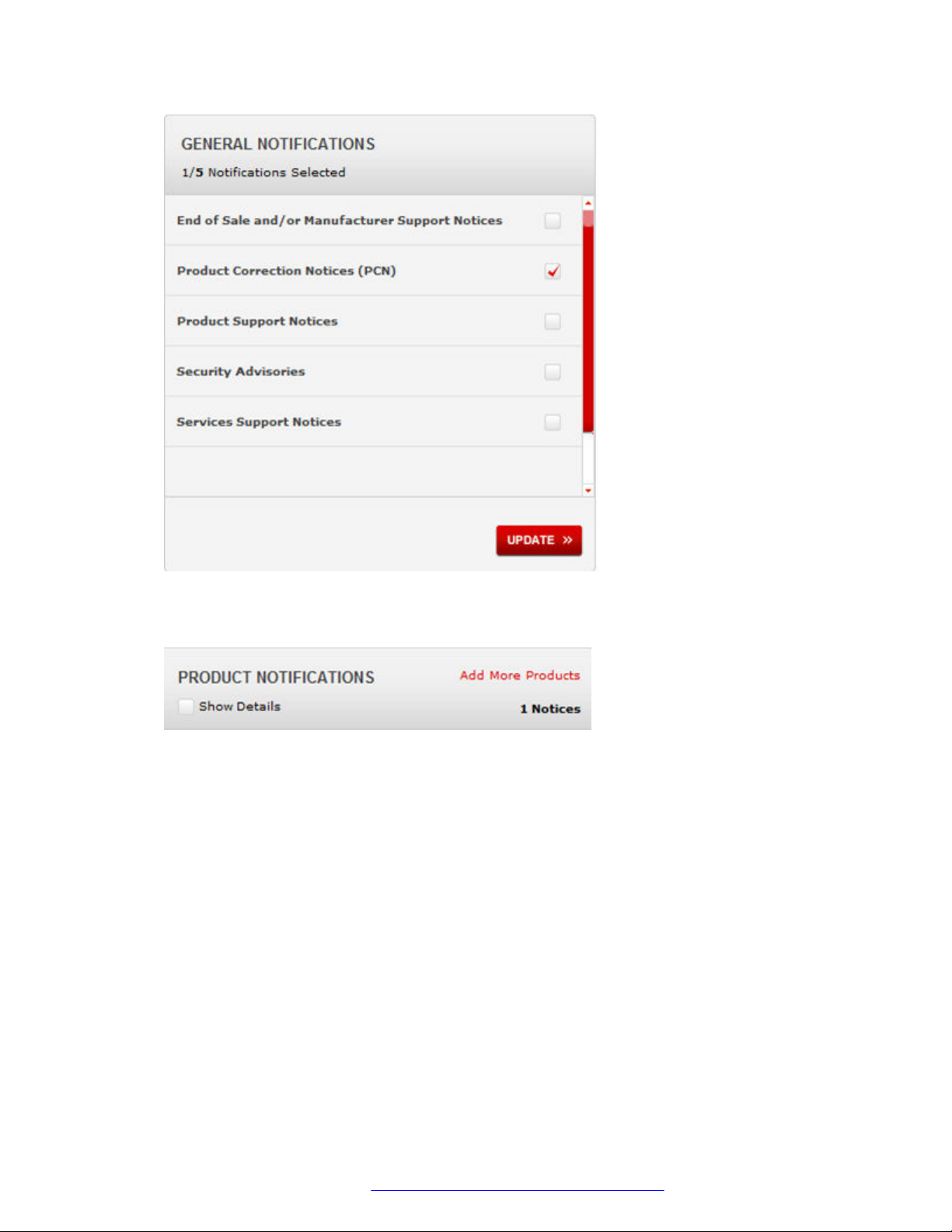
5. In the GENERAL NOTIFICATIONS area, select the required documentation types, and then
click UPDATE.
https://support.avaya.com.
October 2015 Quick Start Configuration for Avaya ERS 5900 Series 8
Comments on this document? [email protected]
Page 9
Related resources
6. Click OK.
7. In the PRODUCT NOTIFICATIONS area, click Add More Products.
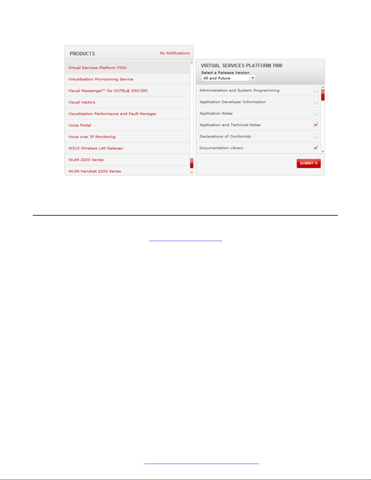
8. Scroll through the list, and then select the product name.
9. Select a release version.
10. Select the check box next to the required documentation types.
October 2015 Quick Start Configuration for Avaya ERS 5900 Series 9
Comments on this document? [email protected]
Page 10
Introduction
11. Click Submit.
Support
Go to the Avaya Support website at http://support.avaya.com for the most up-to-date
documentation, product notices, and knowledge articles. You can also search for release notes,
downloads, and resolutions to issues. Use the online service request system to create a service
request. Chat with live agents to get answers to questions, or request an agent to connect you to a
support team if an issue requires additional expertise.
October 2015 Quick Start Configuration for Avaya ERS 5900 Series 10
Comments on this document? [email protected]
Page 11

Chapter 2: New in this release
The following sections detail what is new in Quick Start Configuration for Avaya Ethernet Routing
Switch 5900 Series, NN47211-500 for Release 7.0.1.
Features
There are no new features in this document.
Other changes
See the following section for information about changes that are not feature-related.
IPv6 management process-redirect
The procedure is updated to include the command default ipv6 mgmt interface
[ process-redirect ]. For more information, see
IPv6 address on page 64.
Configuring an out-of-band management
October 2015 Quick Start Configuration for Avaya ERS 5900 Series 11
Comments on this document? [email protected]
Page 12

Chapter 3: Fundamentals
Provisioning follows hardware installation.
The Quick Start Configuration for Avaya Ethernet Routing Switch 5900 Series, NN47211-500
includes the minimum, but essential, configuration steps to:
• Provide a default, starting point configuration
• Establish a management interface
• Establish basic security on the node
The shipment includes the following:
• An installation kit
• A foldout poster, Quick Install for Avaya Ethernet Routing Switch 5900 Series, NN47211-303.
For more information about hardware specifications and installation procedures, see Installing
Avaya Ethernet Routing Switch 5900 Series, NN47211-300.
For more information about how to configure security, see Configuring Security on Avaya Ethernet
Routing Switch 5900 Series, NN47211-505.
To download and print selected technical publications and release notes directly from the Internet,
go to http://support.avaya.com.
System connection
Use the console cable to connect the terminal to the switch console port. The console cable and
connector must match the console port on the switch (DB-9 or RJ-45, depending on your model).
The following are the default communication protocol settings for the console port:
• 9600 baud
• 8 data bits
• 1 stop bit
• No parity
• No flow control
• VT100 or VT100/ANSI Terminal Protocol
October 2015 Quick Start Configuration for Avaya ERS 5900 Series 12
Comments on this document? [email protected]
Page 13

System Logon
To use the console port, you need the following equipment:
• A terminal or TeleTypewriter (TTY)-compatible terminal, or a portable computer with a serial
port and terminal-emulation software.
• An Underwriters Laboratories (UL)-listed straight-through or null modem RS-232 cable with a
female DB-9 connector for the console port on the switch. The other end of the cable must use
a connector appropriate to the serial port on your computer or terminal.
You must shield the cable that connects to the console port to comply with emissions regulations
and requirements.
System Logon
After the platform boot sequence is complete, a logon prompt appears. The following table shows
the default values for logon and password for console and Telnet sessions.
Table 1: Access levels and default logon values
Access level Description Default Logon Default Password
Read-only Permits view-only configuration
and status information. Is
equivalent to Simple Network
Management Protocol (SNMP)
read-only community access.
Read/write View and change configuration
and status information across the
switch. You can change security
and password settings. This
access level is equivalent to
SNMP read/write community
access.
RO user
RW secure
Secure and nonsecure protocols
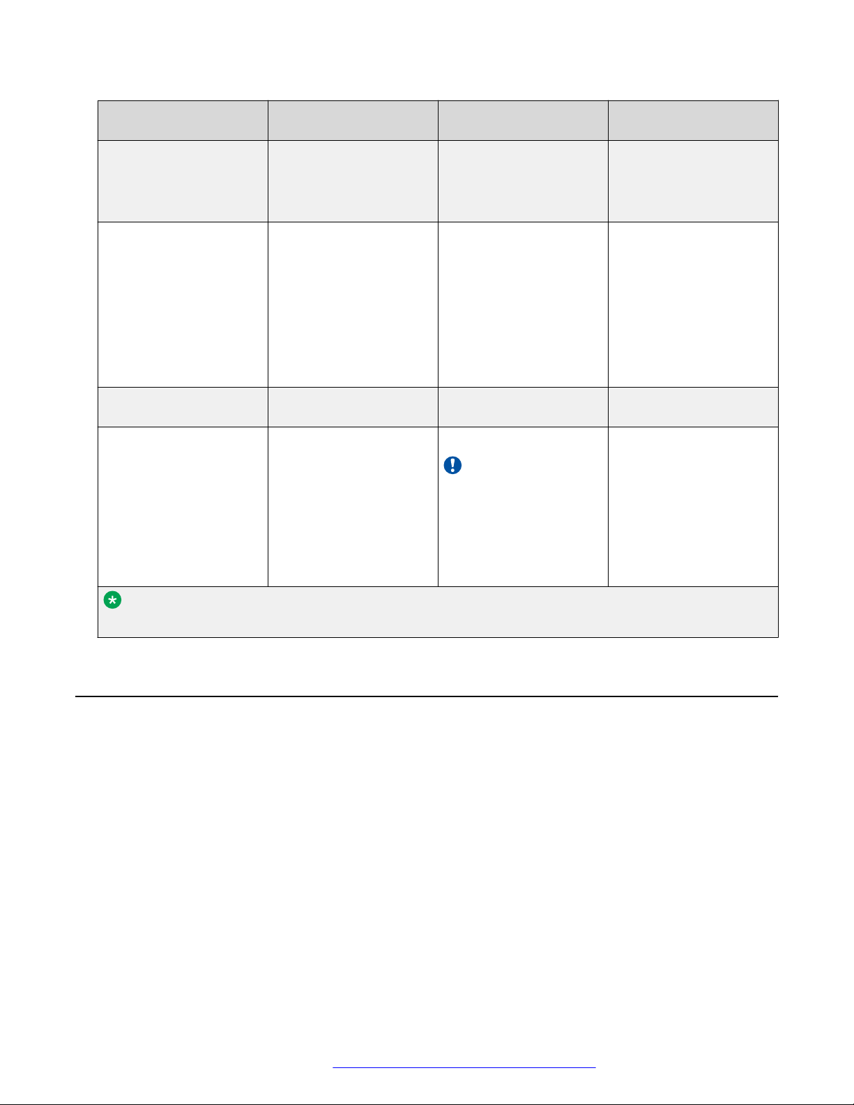
The following table describes the secure and nonsecure protocols that the switch supports.
Table 2: Secure and nonsecure protocols
Nonsecure protocols Default status Equivalent secure
protocols
FTP Disabled SCP Disabled
Default status
Table continues…
October 2015 Quick Start Configuration for Avaya ERS 5900 Series 13
Comments on this document? [email protected]
Page 14
Fundamentals
Nonsecure protocols Default status Equivalent secure
protocols
Telnet Enabled SSH v1, v2
Avaya recommends that
you use SSHv2 instead
of SSHv1.
SNMPv1, SNMPv2 Enabled SNMPv3
You must load the
DES/AES image on the
platform to use SNMPv3.
For more information,
see Configuring Security
on Avaya Ethernet
Routing Switch 5900
Series, NN47211-505.
Rlogin Disabled Secure SHell (SSH) v1,v2Disabled
HTTP Disabled HTTPS
Important:
Avaya recommends
that you take the
appropriate security
precautions within
the network if you
use HTTP.
Default status
Disabled
Disabled
Enabled
Note:
On SSH, by default, HTTP is enabled and HTTPS is disabled.
Out-of-band management
Out-of-band management allows IPv4 or IPv6 switch or stack management using the dedicated outof-band management port. Out-of-band management supports Telnet, Secure Shell (SSH) protocol,
Simple Network Management Protocol (SNMP), HTTP, or HTTPS, without requiring an in-band
management VLAN.
To configure out-of-band management, you assign an IP address to the RJ-45 Ethernet
management port for a switch or stack. You can configure a specific out-of-band management
default gateway, which takes precedence over the in-band default gateway. If you do not configure
an out-of-band management default gateway, the in-band default gateway is used for out-of-band
switch or stack management.
October 2015 Quick Start Configuration for Avaya ERS 5900 Series 14
Comments on this document? [email protected]
Page 15

Out-of-band management
Note:
The out-of-band switch or stack management IP address must be different than the in-band IP
address and belong to a different subnet.
You can use the out-of-band management port to perform tasks such as downloading software
images and, when the SNMP server is enabled, access the Enterprise Device Manager (EDM)
interface for a switch or stack. To access EDM, you type the out-of-band management IP address in
the address bar of an Internet browser.
The out-of-band management port supports full auto negotiation, which enables management
stations to connect at any of the supported speeds or duplexes.
Stack mode
In stack mode, when you use the unit, switch, or stack parameters, the device assigns the IPv4 or
IPv6 address to the management stack. If a management stack IP address is in use, you can only
access the stack through the management port base unit. If the base unit goes down, the stack
management IP address becomes unreachable and the switch management IP address becomes
status up.
Only the base unit allows all commands for out-of-band management. if the base unit leaves the
stack, the stack IP addresses and priveleges transfer to the temporary base unit (TBU). You need a
link in the management port TBU for the IP address to be operational.
On the base unit, if you configure the IP stack address, the base unit is the only active IP address in
the stack. On the non-base units, the IP addresses you configure only become active and reachable
if they become stand alone.
Stand alone mode
In stand alone mode, you assign the IPv4 or IPv6 address only to the switch. You can configure IP
addresses on every switch in the stack.
On the non-base units, the IP addresses you configure only become active and reachable if they
become stand alone.
Considerations and limitations
The following considerations and limitations apply when you configure and use out-of-band
management:
• You must configure all out-of-band management IP addresses for a stack to the same subnet.
• You can configure only one out-of-band management default gateway for each stack.
• You cannot automatically obtain an out-of-band management IP address using BootP or
DHCP.
• With out-of-band management you can issue the ping command from the out-of-band
management port on a stack base unit only.
• With out-of-band management you can only download a software image, or load a
configuration file from the base unit in a stack.
• You can access a management stack from the out-of-band management port on the stack
base unit only.
October 2015 Quick Start Configuration for Avaya ERS 5900 Series 15
Comments on this document? [email protected]
Page 16

Fundamentals
• You can configure both an in-band and out-of-band management IP:
- The out-of-band management default gateway takes precedence over the in-band
management default gateway.
- In Layer 2 mode, once an out-of-band management default gateway is configured, the inband management address is reachable only through a directly attached subnet for the
management VLAN.
- In Layer 3 mode, you must configure a management route to maintain connectivity with the
management network when you use out-of-band management.
• The MAC address for the out-of-band management port is created using the switch MAC
address plus the management offset. The management offset value for the primary out-of-band
management port is 0x300 and the management offset value for the secondary out-of-band
management port is 0x301.
• The out-of-band management port speed is automatically negotiated, however, you can
change it manually.
• The out-of-band management port does not support generation or processing of Autotopology
packets when an out-of-band management IP is configured.
• RADIUS authentication is not supported for the out-of-band management IP.
New unit Quick Configuration
You can use the new unit Quick Configuration feature to create a default configuration that applies
to any new unit joining the stack. Quick Configuration can configure the VLAN IDs, port speed,
PVID, tagging, and spanning tree groups for the new unit without resetting the stack.
Password encryption
The local passwords for the switch are stored in the configuration file, encrypted with an Avaya
proprietary algorithm.
Important:
For security reasons, Avaya recommends that you configure the passwords to values other than
the factory defaults.
For more information about configuring passwords, see:
Using ACLI and EDM on Avaya Ethernet Routing Switch 5900 Series, NN47211-104
Configuring Security on Avaya Ethernet Routing Switch 5900 Series, NN47211-505
October 2015 Quick Start Configuration for Avaya ERS 5900 Series 16
Comments on this document? [email protected]
Page 17

Quick Start
You can use the install command in Avaya Command Line Interface (ACLI) or the Quick Start
menu in Enterprise Device Manager (EDM) to configure the following:
• quick start VLAN
• in-band IP address and subnet mask
• default gateway
• management subnet mask, management IP address and management default gateway
• read-only and read-write community strings
• IPv6 in-band address and IPv6 default gateway
• management IPV6 address and management IPV6 default gateway
Note:
When you reset the switch to factory default, the setup utility does not start automatically. Use
the install command to start the setup utility. The default IP address of the switch is
192.168.1.1 if the switch does not get its IP address from another source.
Quick Start
Enterprise Device Manager
Enterprise Device Manager (EDM) is an embedded graphical user interface (GUI) that you can use
to manage and monitor the platform through a standard web browser. EDM is embedded in the
switch software, and the switch operates as a web server, so you do not require additional client
software. For more information about EDM, see Using ACLI and EDM on Avaya Ethernet Routing
Switch 5900 Series, NN47211-104.
If you want to manage the switch from a centralized location through Configuration and
Orchestration Manager (COM) 2.0 and later, Avaya offers optional, product-specific EDM plug-ins
for COM that include other features such as centralized syslog, trap viewer, troubleshooting and
diagnostic tools. For more information, or to purchase plug-ins, go to
Enterprise Device Manager access
To access EDM, open http://<deviceip>/login.html or https://<deviceip>/login.html from either
Microsoft Internet Explorer (minimum version 8.x), or Mozilla Firefox (minimum version 3.x).
Important:
You must enable the web server from ACLI to enable HTTP access to EDM. If you want HTTP
access to the device, you must also disable the web server secure-only option. The web server
secure-only option is enabled by default and allows HTTPS access to the device. Take the
appropriate security precautions within the network if you use HTTP.
www.avaya.com.
October 2015 Quick Start Configuration for Avaya ERS 5900 Series 17
Comments on this document? [email protected]
Page 18
Fundamentals
If you experience issues while connecting to EDM, check the proxy settings. Proxy settings can
affect EDM connectivity to the switch. Clear the browser cache, and do not use a proxy when
connecting to the device.
Default user name and password
The following table contains the default user name and password that you can use to log on to the
switch using EDM. For more information about changing the passwords, see Configuring Security
on Avaya Ethernet Routing Switch 5900 Series, NN47211-505.
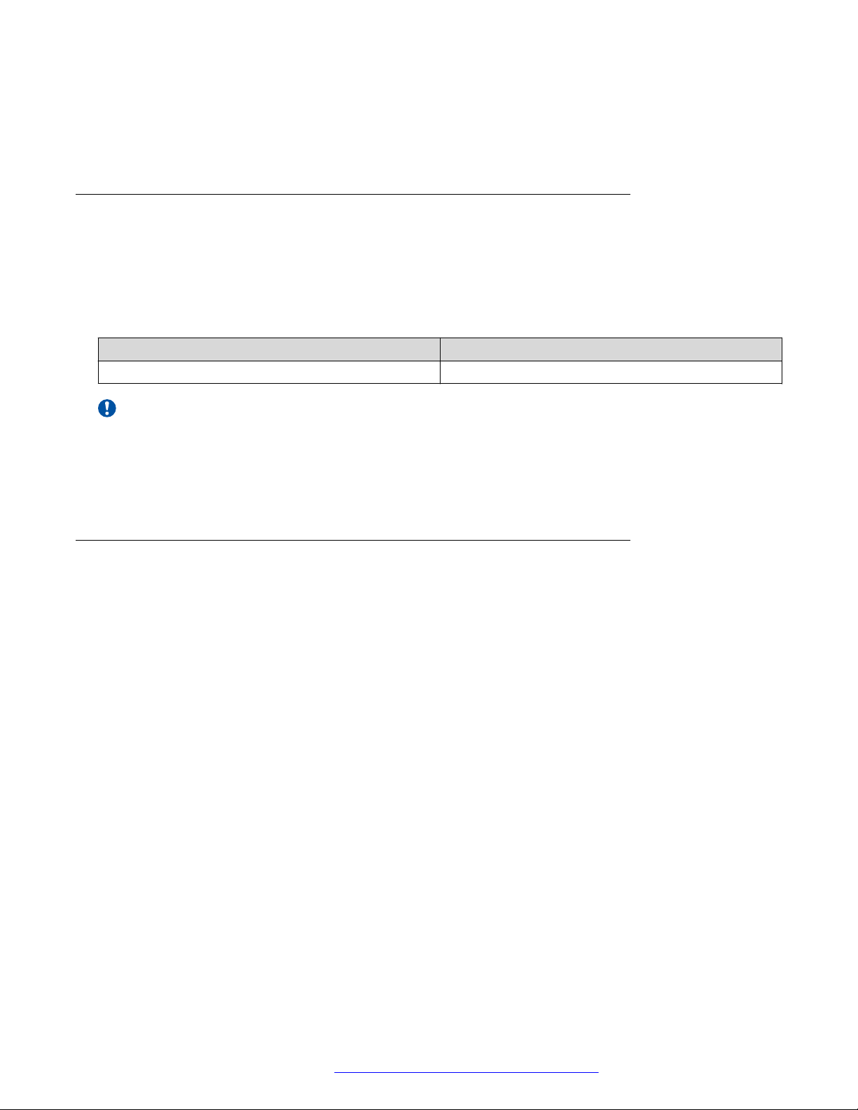
Table 3: EDM default user name and password
User Name Password
admin password
Important:
The default passwords and community strings are documented and well known. Avaya strongly
recommends that you change the default passwords and community strings immediately after
you first log on. For more information about changing user names and passwords, see
Configuring Security on Avaya Ethernet Routing Switch 5900 Series, NN47211-505.
Device Physical View
When you access EDM, the first panel in the work area displays a switch summary view. The tab
behind the summary view is a real-time physical view of the front panel of the device or stack called
the Device Physical View.
Objects in the Device Physical View are:
• Stand-alone switch, called a unit
• Switch stack, called a chassis
• Port
From the Device Physical View, you can:
• Determine the hardware operating status
• Select a switch or a port to perform management tasks on specific objects or view fault,
configuration, and performance information for specific objects
Click to select an object. The system outlines the object in yellow to indicate that the object is
selected.
The conventions on the device view are similar to the actual switch appearance except that LEDs in
Device Physical View do not blink. The LEDs and the ports are color-coded to reflect hardware
status. Green indicates the port is up and running; red indicates that the port is disabled.
October 2015 Quick Start Configuration for Avaya ERS 5900 Series 18
Comments on this document? [email protected]
Page 19
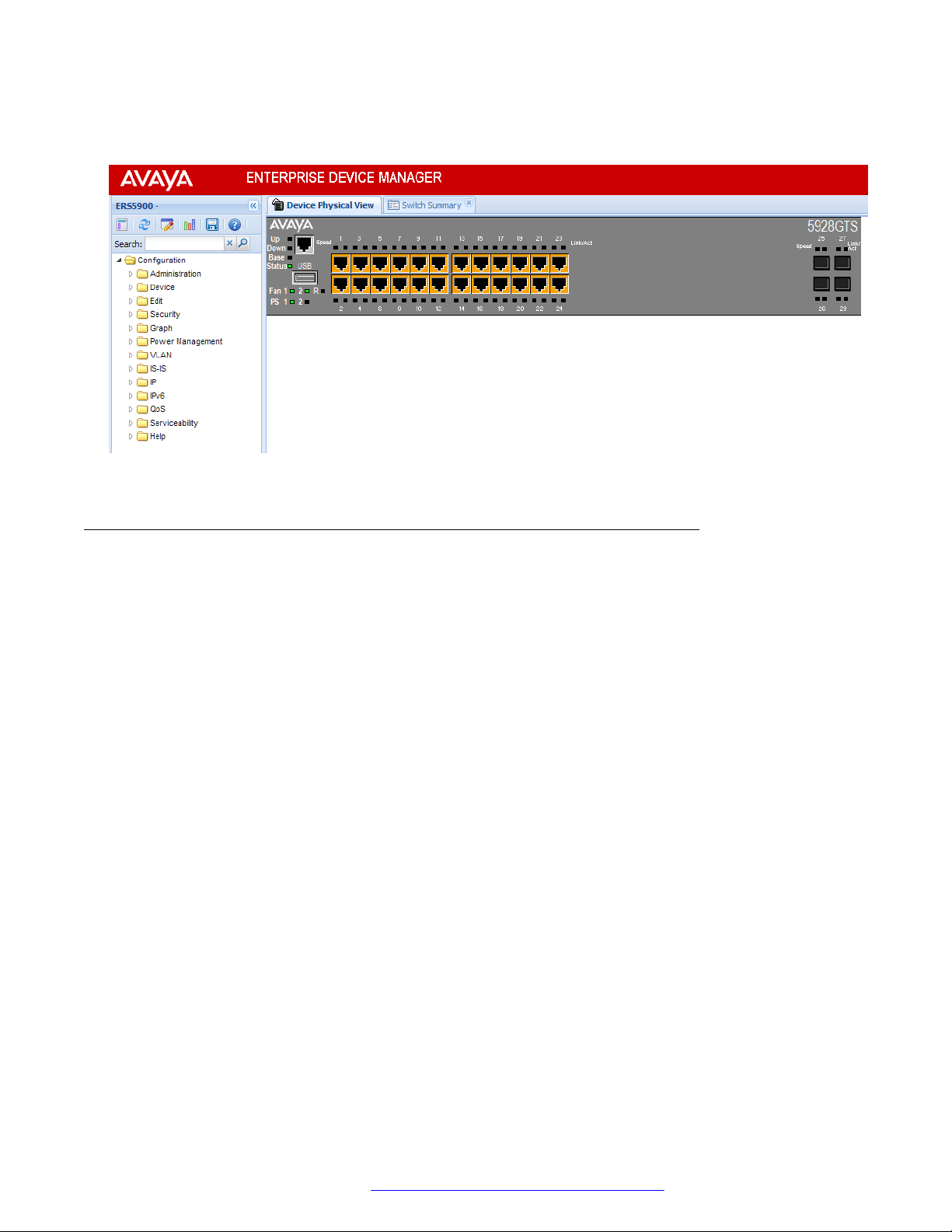
Enterprise Device Manager
From the menu bar, you can click the Device Physical View tab to open the Device Physical View
any time during a session.
Figure 1: Device Physical View
EDM window
The EDM window contains the following parts:
1. Navigation tree—The navigation pane on the left side of the window that displays available
command folders in a tree format.
2. Navigation tree toolbar—The area displays buttons for common functions.
3. Menu bar—The area at the top of the window that displays primary and secondary tabs that
you accessed during the session; the tabs remain available until you close them.
4. Toolbar—The area just below the menu bar that provides quick access to the most common
operational commands such as Apply, Refresh, and Help.
5. Work area—The main area on the right side of the window that displays the dialog boxes
where you view or configure switch parameters.
6. Auto Complete Search — The area between the navigation tree toolbar and the navigation
tree where you can type a partial or complete search string to find menus. When you type
the search string, the navigation tree changes to display only the entries associated with
your search. To return to the full navigation tree display, click the x beside the Auto
Complete Search dialog box.
October 2015 Quick Start Configuration for Avaya ERS 5900 Series 19
Comments on this document? [email protected]
Page 20
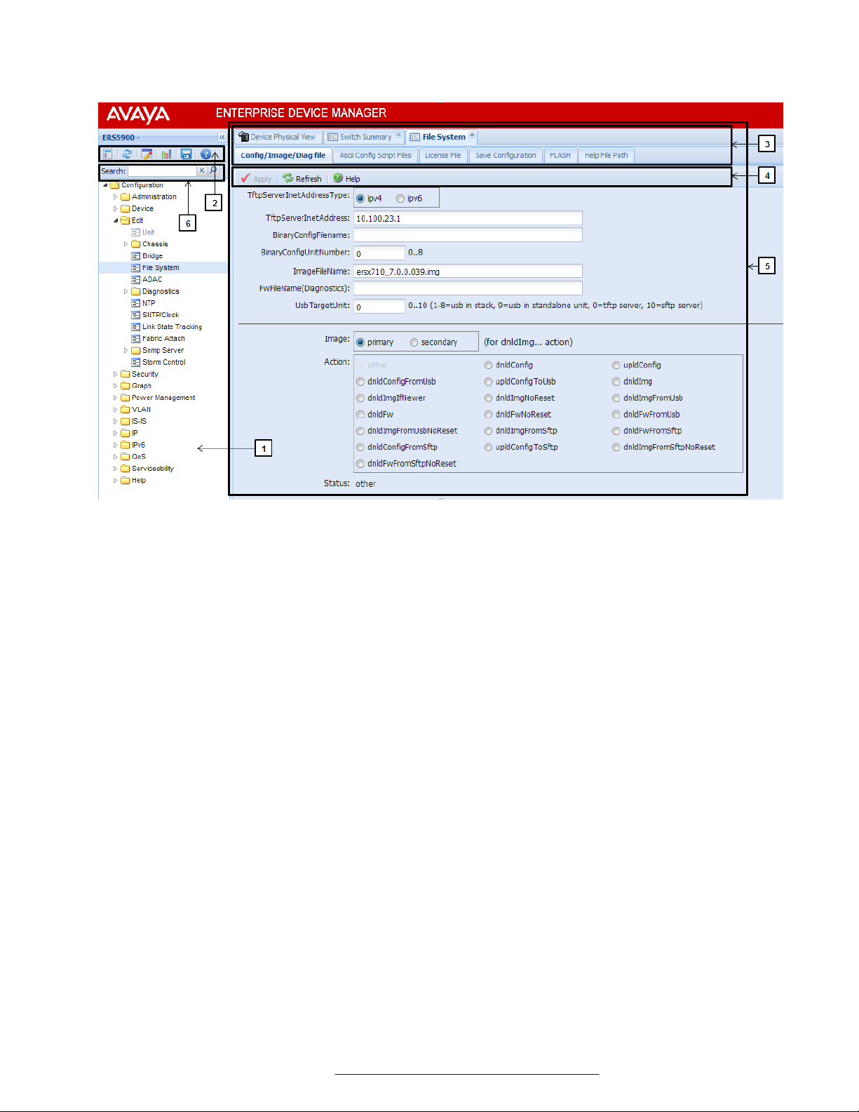
Fundamentals
Figure 2: EDM window
October 2015 Quick Start Configuration for Avaya ERS 5900 Series 20
Comments on this document? [email protected]
Page 21

Chapter 4: Connecting and configuring the
switch
This chapter describes how to connect a terminal to the switch and the required procedures for the
initial provisioning.
Connecting a terminal to the switch
This procedure describes the steps to connect a terminal to the console port on the switch.
Before you begin
To use the console port, you need the following equipment:
• Terminal with AC power cord and keyboard. Any terminal or a computer with an appropriate
terminal emulator can be used as the management station. See Installing Avaya Ethernet
Routing Switch 5900 Series, NN47211-300 for a list of the terminal emulation settings that
must be used with any terminal emulation software used to connect to the switch.
• Use the RJ-45 or DB-9 console cable to connect the switch console port to your management
terminal. See Installing Avaya Ethernet Routing Switch 5900 Series, NN47211-300 for console
port pin-out information. You can use the pin-out information to verify or create a console cable
for use with your maintenance terminal.
Procedure
1. Connect one end of the serial cable to the connector on the terminal or on the computer.
2. Connect the other end of the serial cable to the console port on the switch.
3. Turn the terminal or computer on.
4. Set the terminal protocol on the terminal or terminal emulation program to VT100 or VT100/
ANSI.
5. Connect to the switch using the terminal or terminal emulation application. The Avaya switch
banner displays when you connect to the switch through the console port.
6. Press Ctrl+Y to obtain a CLI prompt.
The switch only supports the Avaya CLI. The old Bay Stack menu interface is not supported
on this product.
October 2015 Quick Start Configuration for Avaya ERS 5900 Series 21
Comments on this document? [email protected]
Page 22

Connecting and configuring the switch
Configuring the switch
Use the procedures in this section to configure the switch using Quick Start.
Configuring Quick Start using ACLI
The Install script consists of a series of prompts that are used to set up the minimum
configuration information.
You must enter the following information when prompted:
• Quick start VLAN
• IP address
• Subnet mask
• Default gateway
• Management subnet mask
• Management IP address
• Management default gateway
• Read-only community string
• Read-write community string
• Management IPV6 address
• Management IPV6 default gateway
Before you begin
• Connect to the switch using the terminal or terminal emulation application.
Procedure
1. Press
CTRL + Y to obtain a CLI prompt.
2. Enter enable
3. Enter install
The switch setup utility banner appears.
4. Enter the VLAN ID for the Quick Start at the following prompt:
Please provide the Quick Start VLAN <1–4094> [1]:
5. Enter the IP address at the following prompt:
Please provide the in-band IP Address[192.168.1.1]:
6. Enter the sub-net mask at the following prompt:
October 2015 Quick Start Configuration for Avaya ERS 5900 Series 22
Comments on this document? [email protected]
Page 23

Please provide the in-band sub-net mask [255.255.255.0]:
7. Enter the default gateway IP address at the following prompt:
Please provide the Default Gateway [0.0.0.0]:
8. Enter the management sub-net mask at the following prompt:
Please provide the management sub-net mask[0.0.0.0]:
9. Enter the management IP address at the following prompt:
Please provide the management IP Address[0.0.0.0]:
10. Enter the management default gateway at the following prompt:
Please provide the management Default Gateway[0.0.0.0]:
11. Enter the read only community string at the following prompt:
Please provide the Read-Only Community String [**********]:
12. Enter the read write community string at the following prompt::
Please provide the Read-Write Community String [**********]:
Configuring the switch
13. Enter the in-band IPv6 address at the following prompt:
Please provide the in-band IPV6 Address/Prefix_length [ : :/0]:
14. Enter the in-band IPv6 default gateway at the following prompt:
Please provide the in-band IPV6 Default Gateway [ : :]:
15. Emter the management IPV6 address at the following prompt:
Please provide the management IPV6 Address/Prefix_length[::/0]:
16. Enter the management IPV6 default gateway at the following prompt:
Please provide the management IPV6 Default Gateway[::]:
Successful completion displays the following message: Basic switch parameters
have been configured and saved.
Example
The following example displays sample output for the install command.
Switch>enable
Switch#install
###############################################################################
Welcome to the 5928GTS setup utility.
You will be requested to provide the switch basic connectivity settings.
After entering the requested info, the configuration will be applied and
stored into the switch NVRAM.
Once the basic connectivity settings are applied, additional configuration
can be done using the available management interfaces.
Use Ctrl+C to abort the configuration at any time.
###############################################################################
October 2015 Quick Start Configuration for Avaya ERS 5900 Series 23
Comments on this document? [email protected]
Page 24

Connecting and configuring the switch
Please provide the Quick Start VLAN <1-4094> [1]:
Please provide the in-band IP Address[192.168.1.1]:
Please provide the in-band sub-net mask[255.255.255.0]:
Please provide the Default Gateway[0.0.0.0]:
Please provide the management sub-net mask[0.0.0.0]:
Please provide the management IP Address[0.0.0.0]:
Please provide the management Default Gateway[0.0.0.0]:
Please provide the Read-Only Community String[**********]:
Please provide the Read-Write Community String[**********]:
Please provide the in-band IPV6 Address/Prefix_length[::/0]:
Please provide the in-band IPV6 Default Gateway[::]:
Please provide the management IPV6 Address/Prefix_length[::/0]:
Please provide the management IPV6 Default Gateway[::]:
###############################################################################
Basic switch parameters have now been configured and saved.
###############################################################################
Switch#
Configuring Quick Start using EDM
Use the following procedure to configure the Quick Start setup mode using EDM.
About this task
You can use Quick Start to quickly setup a new switch or stack.
Procedure
1. From the navigation tree, double-click Administration.
2. In the Administration tree, click Quick Start.
3. In the work area, click the IP/Community/Vlan tab.
4. In the In-Band Switch IP Address field, type a switch or stack IP address.
5. In the In-Band Stack Subnet Mask field, type a subnet mask.
6. In the Default Gateway field, type a gateway IP address.
7. In the Read-Only Community String field, type a community string. Re-type the community
string in the verification field.
8. In the Read-Write Community String field, type a community string. Re-type the community
string in the verification field.
Note:
For security, enter different community strings for Read-Only and Read-Write.
9. In the Quick Start VLAN field, type a VLAN ID ranging from 1 to 4094.
10. On the toolbar, click Apply.
October 2015 Quick Start Configuration for Avaya ERS 5900 Series 24
Comments on this document? [email protected]
Page 25
Configuring the terminal
Configuring the terminal
You can configure the switch terminal settings to suit your preferences for the terminal speed and
display.
About this task
Use the following procedure to configure terminal settings including the terminal connection speed,
and number of characters in the terminal display width and length.
Important:
After you modify the terminal configuration, the new settings are applied to the current active
session and to all future sessions (serial, telnet or SSH). Terminal configuration change does
not affect open concurrent sessions.
Procedure
1. Log on to ACLI to enter User EXEC mode.
2. At the command prompt, enter the following command:
terminal {speed <19200 | 38400 | 9600> | length <0-132> | width
<1-132>}
3. To display the current serial port information, enter the following command:
show terminal
Example
Switch#show terminal
Terminal speed: 9600
Terminal width: 79
Terminal length: 23
Variable definitions
Use the definitions in the following table to use the terminal command.
Variable Definition
length Sets the length of the terminal display in lines. By
default, 23 lines are displayed.
DEFAULT: 23
Important:
If you set the terminal length to 0, the pagination
is disabled and the display scrolls continuously.
speed <19200 | 38400 | 9600> Sets the transmit and receive baud rates for the
terminal.
DEFAULT: 9600
Table continues…
October 2015 Quick Start Configuration for Avaya ERS 5900 Series 25
Comments on this document? [email protected]
Page 26

Connecting and configuring the switch
Variable Definition
width Sets the width of the terminal display in characters.
By default, 79 characters are displayed.
DEFAULT: 79
Configuring BootP on the current instance of the switch or server
About this task
The default operational mode for BootP on the switch is BootP or DefaultIP. The switch requests an
IP address from BootP only if one is not already configured from the console terminal (or if the IP
address is the default IP address 192.168.1.1).
Procedure
1. Enter Global Configuration mode:
enable
configure terminal
2. At the command prompt, enter the following command:
ip bootp server {always | disable | last | default-ip}
Variable definitions
Use the definitions in the following table to use the ip bootp server command.
Variable Definition
always | disable | last | default-ip Specify when to use BootP:
• default-ip—Use BootP or the default IP
• last—Use BootP or the last known address
• disable—Never use BootP
• always—Always use BootP
By default, default-ip is selected.
October 2015 Quick Start Configuration for Avaya ERS 5900 Series 26
Comments on this document? [email protected]
Page 27

Configuring diagnostics quick mode
Configuring diagnostics quick mode
The diagnostics quick mode flag enables you to choose the diagnostic test behavior during boot.
You can enable quick mode boot tests or all the diagnostic tests. The impact to boot time is 15 to 20
seconds when all diagnostic tests run during startup.
The diagnostic quick mode is disabled by default.
Procedure
1. Enter Global Configuration mode:
enable
configure terminal
2. To enable the diagnostics quick mode flag, enter the following command at the command
prompt:
diagnostics-quick-mode enable
3. To disable the diagnostics quick mode flag, enter either of the following commands at the
command prompt:
no diagnostics-quick-mode enable
OR
default diagnostics-quick-mode
4. To display the configuration, enter the following command at the command prompt:
show diagnostics-quick-mode
Example
Enable diagnostics quick mode:
Switch>enable
Switch#configure terminal
Switch(config)#diagnostics-quick-mode enable
Switch(config)#show diagnostics-quick-mode
2013-10-02 08:53:27 GMT+00:00
Diagnostics quick mode: Enabled
Setting user access limitations using ACLI
The administrator can use ACLI to limit user access by creating and maintaining passwords for web,
telnet, and console access. This is a two-step process that requires that you first create the
password and then enable it.
Ensure that you enter Global Configuration mode in ACLI before you start these tasks.
October 2015 Quick Start Configuration for Avaya ERS 5900 Series 27
Comments on this document? [email protected]
Page 28
Connecting and configuring the switch
Setting the read-only and read/write passwords
To require password authentication when a user logs in to a switch, you must edit the password
configuration.
About this task
Follow this procedure to edit the password configuration.
Procedure
1. Enter Global Configuration mode:
enable
configure terminal
2. Enter the following command:
username {RO | RW} password
3. Press Enter.
Variable definitions
Use the definitions in the following table to use the username { RO | RW } password
command.
Variable Definition
{RO | RW} Specify whether the password change is for read-only access or
read-write access.
password Specify password. If password security is disabled, the
password length can be 1 to 255 characters. If password
security is enabled, the range for the password length is 10 to
255 characters.
Enabling and disabling passwords
After you set the read-only and read-write passwords, you can individually enable or disable them
for the various switch-access methods.
About this task
Follow this procedure to enable or disable a password for a specific access method.
Procedure
1. Enter Global Configuration mode:
enable
configure terminal
October 2015 Quick Start Configuration for Avaya ERS 5900 Series 28
Comments on this document? [email protected]
Page 29

Setting user access limitations using Enterprise Device Manager
2. Enter the following command:
cli password {telnet | serial} {none | local | radius | tacacs}
Variable definitions
Use the definitions in the following table to use the cli password command.
Variable Definition
{telnet | serial} Specify whether the password is enabled or disabled for telnet
or the console. Telnet and web access are connected so that
enabling or disabling passwords for one enables or disables
passwords for the other.
none | local | radius | tacacs Specify the password type to modify:
• none: disables the password.
• local: uses the locally defined password for serial console or
telnet access.
• radius: uses RADIUS authentication for serial console or
telnet access.
• tacacs: uses TACACS+ authentication, authorization and
accounting (AAA) services for serial console or telnet access.
Setting user access limitations using Enterprise Device
Manager
You can use Enterprise Device Manager (EDM) to limit user access by creating and maintaining
passwords for web, telnet, and console access.
Configuring the console password using EDM
About this task
Use this procedure to configure a password for serial console access to a stack or standalone
switch.
Procedure
1. From the navigation tree, double-click Security.
2. In the Security tree, double-click Web/Telnet/Console.
3. In the work area, click the Console Password tab.
4. Click the arrow on the Console Stack Password Type field.
5. Select a password type from the list.
October 2015 Quick Start Configuration for Avaya ERS 5900 Series 29
Comments on this document? [email protected]
Page 30

Connecting and configuring the switch
6. Type the password for read-only access in the Read-Only Stack Password field.
7. Type the same password for read-only access in the Re-enter to verify field.
8. Type the password for read-write access in the Read-Write Stack Password field.
9. Type the same password for read-write access in the Re-enter to verify field.
10. On the toolbar, click Apply.
Console Password field descriptions
Use the data in the following table to use the Console Password tab to configure console switch
password.
Name Description
Console Stack Password Type Specify the type of password to use. Values include:
• none: Disables the password.
• Local Password: Use the locally-defined
password for serial console access.
• RADIUS Authentication: Use RADIUS
authentication for serial console access.
• TACACS Authentication: Use TACACS+
authentication, authorization and accounting (AAA)
services authentication for console access.
Read-Only Stack Password Specify the read-only password for stack or switch
access.
Read-Write Stack Password Specify the read-write password for stack or switch
access.
Configuring the web and telnet password using EDM
About this task
Use the following procedure to configure a password for web and telnet access to a stack or
standalone switch.
Procedure
1. From the navigation tree, double-click Security.
2. In the Security tree, click Web/Telnet/Console.
3. In the work area, click the Web/Telnet tab.
4. Click the arrow on the Web/Telnet Switch Password Type field.
5. Select a password type from the list.
6. Type the password for read-only access in the Read-Only Stack Password field.
October 2015 Quick Start Configuration for Avaya ERS 5900 Series 30
Comments on this document? [email protected]
Page 31

Configuring the ACLI banner
7. Type the same password for read-only access in the Re-enter to verify field.
8. Type the password for read-write access in the Read-Write Switch Password field.
9. Type the same password for read-write access in the Re-enter to verify field.
10. On the toolbar, click Apply.
Field descriptions
Use the descriptions in the following table to configure the web and telnet switch password.
Field Description
Web/Telnet Stack Password Type Specify the type of the password to use. Values
include:
• none—Disables the password
• Local Password—Uses the locally defined
password for web and telnet access.
• RADIUS Authentication—Uses RADIUS password
authentication for web and telnet access.
• TACACS Authentication—Uses TACACS+
authentication, authorization and accounting (AAA)
services authentication for web and telnet access.
Read-Only Stack Password Specify the read-only password for stack or switch
access. The maximum length of the password is 15
characters.
Read-Write Switch Password Specify the read-write password for stack or switch
access. The maximum length of the password is 15
characters.
Configuring the ACLI banner
You can configure the banner that is presented when a user logs on to the switch through ACLI to a
user-defined value.
You can use the custom logon banner to display company information, such as company name and
contact information.
The banner cannot exceed 1539 bytes, or 19 rows by 80 columns plus line termination characters.
The banner control setting is saved to NVRAM, and both the banner file and control setting are
distributed to all units within a stack.
About this task
Follow this procedure to configure the ACLI banner.
October 2015 Quick Start Configuration for Avaya ERS 5900 Series 31
Comments on this document? [email protected]
Page 32

Connecting and configuring the switch
Procedure
1. Enter Global Configuration mode:
enable
configure terminal
2. Configure the switch to use a custom banner or use the default banner:
banner {custom | static}
3. Create a custom banner:
banner <line_number> "<LINE>"
4. Save the configuration:
save config
5. Display the banner information:
show banner
6. Log on again to verify the configuration.
7. (Optional) Disable the banner:
no banner
Example
The following is an example of ACLI banner configuration:
Switch>enable
Switch#configure terminal
Enter configuration commands, one per line. End with CNTL/Z.
Switch(config)#show banner
Current banner setting: STATIC
Switch(config)#banner custom
Switch(config)#banner 1 "My Company Name"
Switch(config)#banner 2 "123A My Address Avenue My Town CA 12345"
Switch(config)#banner 3 "Phone: (123) 555-5555 * Fax (123) 555-5555"
Switch(config)#banner 4 "http://www.mycompanywebsite.com"
Switch(config)#save config
Switch(config)#show banner
Current banner setting: CUSTOM
Switch(config)#end
Switch#exit
My Company Name
123A My Address Avenue My Town CA 12345
Phone: (123) 555-5555 * Fax (123) 555-5555
http://www.mycompanywebsite.com
Enter Ctrl-Y to begin.
***************************************************************
*** Ethernet Routing Switch <Switch> ***
*** Avaya ***
*** Copyright (c) 1996-2014, All Rights Reserved ***
October 2015 Quick Start Configuration for Avaya ERS 5900 Series 32
Comments on this document? [email protected]
Page 33
Configuring system identification
*** ***
*** HW:R0D.7 FW:0.0.0.2c SW:v7.0.0.056 ***
***************************************************************
Variable definitions
Use the definitions in the following table to use the banner command.
Variable Definition
custom Disable the use of the default banner.
static Activate the use of the default banner.
<line_number> Banner line number you are configuring. The range
is 1 to 19
<LINE> Specify the characters in the line number.
Configuring system identification
About this task
You can configure system identification to specify the system name, contact person, and location of
the switch, and to add a trap receiver to the trap-receiver table.
Procedure
1. Enter Global Configuration mode:
enable
configure terminal
2. Enable the Simple Network Management Protocol (SNMP) server:
snmp-server enable
3. Configure the read-only community name:
snmp-server community ro
Note:
Enter the community string twice.
If you ran the install script to set up the configuration information, the read-only
community name is already configured.
4. Configure the read-write community name:
snmp-server community rw
October 2015 Quick Start Configuration for Avaya ERS 5900 Series 33
Comments on this document? [email protected]
Page 34
Connecting and configuring the switch
Note:
Enter the community string twice.
If you ran the install script to set up the configuration information, the read-write
community name is already configured.
5. Configure the system name:
snmp-server name <text>
6. Configure the system contact:
snmp-server contact <text>
7. Configure the location:
snmp-server location <text>
8. Configure the SNMP host to add a trap receiver to the trap-receiver table:
snmp-server host <host-ip> <community-string>
Variable definitions
Use the definitions in the following table to use the snmp-server name command.
Table 4: snmp-server name command
Variable Definition
<text> Specify the SNMP system name value. Enter an
alphanumeric string of up to 255 characters.
Note:
On the console, the SNMP server name is
truncated. On the web interface, the full SNMP
server name appears.
Use the definitions in the following table to use the snmp-server contact command.
Table 5: snmp-server contact command
Variable Definition
<text> Specify the SNMP system contact value. Enter an
ASCII string of up to 255 characters.
Use the definitions in the following table to use the snmp-server location command.
October 2015 Quick Start Configuration for Avaya ERS 5900 Series 34
Comments on this document? [email protected]
Page 35
Enabling logging
Table 6: snmp-server location command
Variable Definition
<text> Specify the SNMP system location value. Enter an
alphanumeric string of up to 255 characters.
Use the definitions in the following table to use the snmp-server host command.
Table 7: snmp-server host command
Variable Definition
<host-ip> Specify an IPv4 or IPv6 address for a host intended
to be the trap destination.
<community-string> If you are using the proprietary method for SNMP,
enter a community string that works as a password
and permits access to the SNMP protocol.
Enabling logging
Use this procedure to enable the logging of system messages. For more information about logging,
see Logs Reference for Avaya Ethernet Routing Switch 2000, 3000, 4000, 5000, 5900 Series and
Virtual Services Platform 7000 Series, NN47216-600.
Procedure
1. Enter Global Configuration mode:
enable
configure terminal
2. To enable system logging, enter the following command at the command prompt:
logging remote level informational
Configuring Simple Network Time Protocol
The Simple Network Time Protocol (SNTP) feature synchronizes the Universal Coordinated Time
(UTC) to an accuracy within 1 second. This feature adheres to the IEEE RFC 2030 (MIB is the
s5agent). With this feature, the system can obtain the time from any RFC 2030-compliant NTP/
SNTP server.
For more information on SNTP, see Configuring Systems on Avaya Ethernet Routing Switch 5900
Series, NN47211-501.
October 2015 Quick Start Configuration for Avaya ERS 5900 Series 35
Comments on this document? [email protected]
Page 36
Connecting and configuring the switch
About this task
Use this procedure to configure the Network Time Protocol (NTP) servers for SNTP.
Procedure
1. Enter Global Configuration mode:
enable
configure terminal
2. Enter the following command to configure the SNTP server primary IP address:
sntp server primary address [<A.B.C.D> |
<primary_server_ipv6address>]
3. Enter the following command to configure the SNTP secondary server IP address:
sntp server secondary address [<A.B.C.D> |
<secondary_server_ipv6address>]
Note:
SNTP supports primary and secondary NTP servers. The system attempts to access the
secondary NTP server only if the primary NTP server is unresponsive.
4. Enter the following command to enable SNTP:
sntp enable
Variable definitions
Use the definitions in the following table to use the sntp server command.
Variable Definition
<A.B.C.D> Enter the IP address of the NTP server.
<primary_server_ipv6address> Enter the IPv6 address of the primary NTP server.
<secondary_server_ipv6address> Enter the IPv6 address of the secondary NTP server.
Configuring real-time clock
About this task
Configure the real-time clock (RTC) to provide the switch with time information. The RTC provides
the switch with time information in the instance that SNTP time is not available.
Procedure
1. Log on to ACLI to enter User EXEC mode.
October 2015 Quick Start Configuration for Avaya ERS 5900 Series 36
Comments on this document? [email protected]
Page 37
Configuring local time zone
2. Enter Privileged EXEC mode:
enable
3. Enter the following command to configure RTC:
clock set {hh:mm:ss <1–31> [<1–31> {[MONTH <2005–2099>] [MONTH <1–
31> <2005–2099>]} [LINE]}
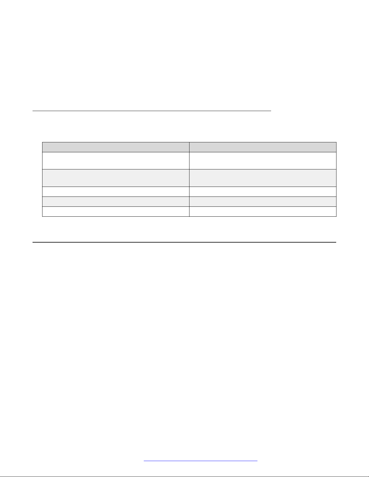
Variable definitions
Use the definitions in the following table to use the clock set command.
Variable Value
<LINE> Specify a string in the format of mmddyyyyhhmmss
that defines the current local time.
<hh:mm:ss> Specify the current local time in the hh:mm:ss
format.
<1–31> RTC date
<MONTH> RTC month
<2005–2099> RTC year
Configuring local time zone
Configure the time zone to use an internal system clock to maintain accurate time. The time zone
data does not include daylight saving time changes. You must configure daylight saving time.
About this task
Use this procedure to configure the local time zone.
Procedure
1. Enter Global Configuration mode:
enable
configure terminal
2. Enter the following command to enable SNTP:
sntp enable
3. Enter the following command to configure the time zone:
clock time-zone <zone> <hours> [minutes]
4. Enter the following command to configure daylight saving time:
October 2015 Quick Start Configuration for Avaya ERS 5900 Series 37
Comments on this document? [email protected]
Page 38
Connecting and configuring the switch
clock summer-time zone date day month year hh:mm day month year
hh:mm [offset]
5. Save the changed configuration.
Example
Configuring the time zone
Switch>enable
Switch#configure terminal
Switch(config)#clock time-zone PST -8
This command sets the time zone to UTP minus 8 hours and the time zone is displayed as "PST."
Configuring daylight saving time
Switch(config)#clock summer-time BST date 28 Mar 2013 2:00 30 Aug 2013
15:00 +60
This command sets the daylight saving time to begin at 02:00 on March 28, 2013 and end on
August 30, 2013 at 15:00. The change to daylight saving time moves the clock forward by 60
minutes and the time zone is displayed as "BST". These changes to and from daylight saving time
occur automatically.
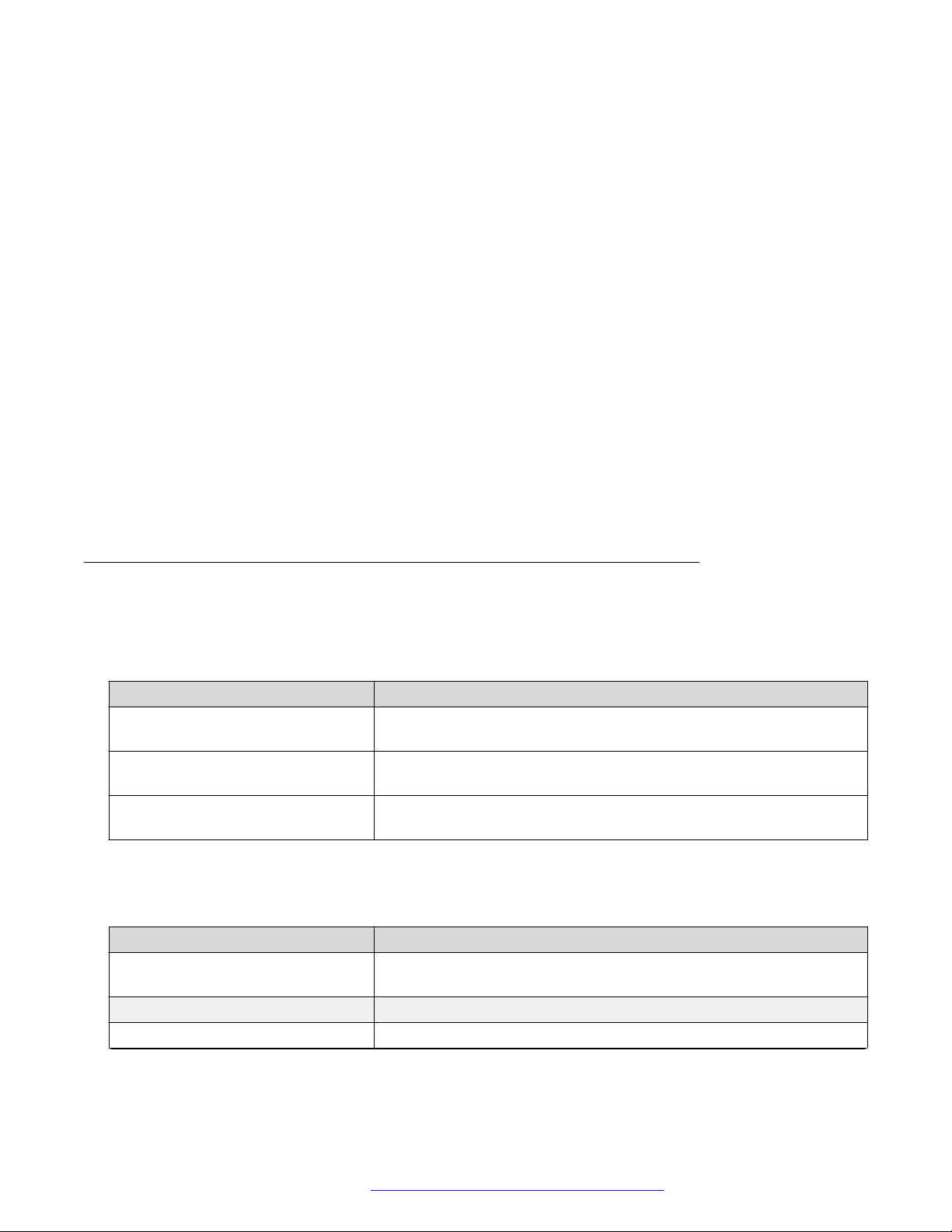
Variable definitions
Use the definitions in the following table to use the clock time-zone command.
Table 8: clock time-zone command
Variable Definition
<zone> Time zone acronym to be displayed when showing system time (up to
4 characters).
<hours> Difference from UTC in hours. This can be any value between -12
and +12.
[minutes] Optional: This is the number of minutes difference from UTC. Minutes
can be any value between 0 and 59.
Use the definitions in the following table to use the clock summer-time zone command.
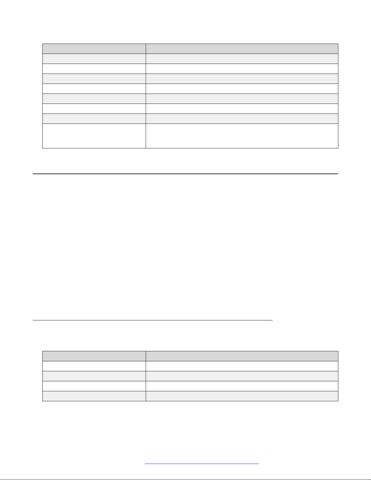
Table 9: clock summer-time zone command
Variable Definition
date Indicates that daylight saving time you set to start and end on the
specified days every year.
day Day to start daylight saving time.
month Month to start daylight saving time.
Table continues…
October 2015 Quick Start Configuration for Avaya ERS 5900 Series 38
Comments on this document? [email protected]
Page 39
Configuring the clock
Variable Definition
year Year to start daylight saving time.
hh:mm Hour and minute to start daylight saving time.
day Day to end daylight saving time.
month Month to end daylight saving time.
year Year to end daylight saving time.
hh:mm Hour and minute to end daylight saving time.
offset Number of minutes to add during the summertime.
zone The time zone acronym to be displayed when daylight saving time is
in effect. If unspecified, the acronym defaults to the time zone
acronym that was configured when the time zone was configured.
Configuring the clock
In addition to SNTP time configuration, a clock provides the switch with time information. This clock
provides the switch information whent SNTP time is not available.
About this task
Use this procedure to configure the time source for the switch.
Procedure
1. Enter Global Configuration mode:
enable
configure terminal
2. Enter the following command:
clock source {ntp | sntp | rtc | sysUpTime }
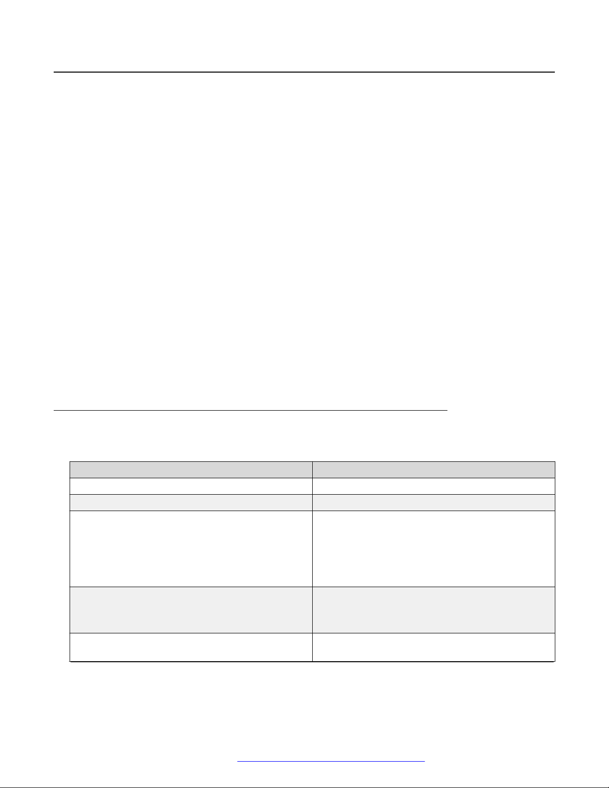
Variable definitions
Use the definitions in the following table to use the clock source command.
Variable Definition
ntp Configure NTP as the time source.
sntp Configure SNTP as the time source.
rtc Specifies Real Time Clock (RTC) as the time source.
sysUpTime Configure System Up Time as the time source.
October 2015 Quick Start Configuration for Avaya ERS 5900 Series 39
Comments on this document? [email protected]
Page 40
Connecting and configuring the switch
Configuring a static route
Create static routes to manually configure a path to destination IP address prefixes.
Procedure
1. Enter Global Configuration mode:
enable
configure terminal
2. Enter the following command to enable IP routing globally:
ip routing
3. Enter the following command to configure an IP address on a VLAN:
ip address <ip address> <mask> [<MAC-offset>]
4. Enter the following command to configure a static route:
ip route <destination ip> <mask> <next-hop> {<cost> | disable |
enable | weight <cost>}
5. Enter the following command to display all the static routes:
show ip route static [<dest-ip>] [-s <subnet> <mask>]
6. Save the configuration.
Variable definitions
Use the definitions in the following table to use the ip route command.
Variable Definition
<ipaddr> Specify the IP address to attach to the VLAN.
<mask> Specify the subnet mask to attach to the VLAN
<MAC-offset> Specify the value used to calculate the VLAN MAC
address, which is offset from the switch MAC
address. The valid range is 1 to 256. Specify the
value 1 for the Management VLAN only. If no MAC
offset is specified, the switch applies one
automatically.
<destination ip> Specify the destination IP address for the route being
added.
0.0.0.0 is considered the default route.
<mask> Specify the destination subnet mask for the route
being added.
Table continues…
October 2015 Quick Start Configuration for Avaya ERS 5900 Series 40
Comments on this document? [email protected]
Page 41
Enabling remote access
Variable Definition
<next-hop> Specify the next-hop IP address for the route being
added.
<cost> Specify the weight, or cost, of the route being added.
Range is 1 to 65535.
enable Enable the specified static route.
disable Disable the specified static route.
weight <cost> Change the weight, or cost, of an existing static
route. Range is 1 to 65535.
Enabling remote access
You can enable remote access for telnet, SSH (on SSH software images), SNMP, and webpage
access.
For more information, see Using ACLI and EDM on Avaya Ethernet Routing Switch 5900 Series,
NN47211-104 and Configuring Systems on Avaya Ethernet Routing Switch 5900 Series,
NN47211-501.
About this task
Use the following procedure to enable and configure remote access to the management features of
the switch.
Procedure
1. Enter Global Configuration mode:
enable
configure terminal
2. To enable telnet remote access, enter the following command:
telnet-access enable
3. To enable SSH remote access, enter the following command:
ssh
4. To enable SNMP remote access, enter the following command:
snmp-server enable
5. To enable webpage remote access, enter the following command:
web-server enable
October 2015 Quick Start Configuration for Avaya ERS 5900 Series 41
Comments on this document? [email protected]
Page 42

Connecting and configuring the switch
Example
The following is an example of enabling telnet remote access:
Switch>enable
Switch#configure terminal
Enter configuration commands, one per line. End with CNTL/Z.
Switch(config)#telnet-access enable
Switch(config)#
Using telnet to log on to the device
About this task
Use telnet to log on to the device and remotely manage the switch.
Procedure
1. From a computer or terminal, start a telnet session:
telnet <IPv4_address>
where <IPv4_address> is the IP address of the switch. The stand-alone units use the default
IP address of 192.168.1.1 if the switch does not obtain its IP address from another source.
2. Enter the user ID and password when prompted.
Enabling the web server management interface
The web server must be enabled to access Enterprise Device manager (EDM). If you do not want
EDM to be accessible on the device, disable the web server. By default, the web server is enabled.
About this task
Use this procedure to enable the web server.
Procedure
1. Enter Global Configuration mode:
enable
configure terminal
2. At the command prompt, enter the following command:
web-server enable
October 2015 Quick Start Configuration for Avaya ERS 5900 Series 42
Comments on this document? [email protected]
Page 43

Accessing the switch through the web interface
Accessing the switch through the web interface
You can use EDM to configure and maintain your switch through a web-based graphical user
interface. You can monitor the switch through a web browser from anywhere on the network.
By default, you can access the web interface using Hypertext Transfer Protocol Secure (HTTPS)
only.
For more information about configuring the web server to respond to HTTPS only or to both HTTPS
and Hypertext Transfer Protocol (HTTP) client browser requests, see Configuring Security on Avaya
Ethernet Routing Switch 5900 Series, NN47211-505.
By default, the web interface uses a 15 minute time-out period. If no activity occurs for 15 minutes,
the system logs off the switch web interface, and you must reenter the password information.
To configure inactivity time-out, see Configuring Security on Avaya Ethernet Routing Switch 5900
Series, NN47211-505.
Before you begin
• Ensure that the switch is running.
• Note the switch IP address.
• Ensure that the web server is enabled.
• Note the user name and password.
• Open one of the supported web browsers.
For more information about the supported browsers, see Using ACLI and EDM on Avaya
Ethernet Routing Switch 5900 Series, NN47211-104.
About this task
Use this procedure to access the switch through a web browser.
Procedure
1. Start your web browser.
2. Type the switch IP address as the URL in the Web address field.
http://<IP Address>
OR
https://<IP Address>
3. Enter the user name.
4. Enter the password.
5. Click Log On.
October 2015 Quick Start Configuration for Avaya ERS 5900 Series 43
Comments on this document? [email protected]
Page 44

Connecting and configuring the switch
Enabling or disabling Quick Configuration
Use the following commands to enable or disable Quick Configuration:
Before you begin
Quick Configuration requires a stack.
About this task
The new unit Quick Configuration can store a default configuration that applies to a new unit joining
the stack.
Procedure
1. Enter Global Configuration mode:
enable
configure terminal
2. To enable Quick Configuration, enter the following command:
quickconfig enable
3. To disable Quick Configuration, enter the following command:
no quickconfig enable
4. To default Quick Configuration, enter the following command:
default quickconfig
Next steps
Use the quickconfig start-recording command to record a default configuration that applies
to new units joining the stack.
Recording a Quick Configuration
Use this procedure to record a Quick Configuration:
Before you begin
Quick Configuration requires a stack.
Quick Configuration must be enabled.
About this task
You can use the new unit Quick Configuration feature to create a default configuration that applies
to any new unit joining the stack. You can record the default values for VLAN IDs, port speed,
duplex mode, PVID, tagging, and spanning tree groups for the new unit without the need to reset the
stack.
October 2015 Quick Start Configuration for Avaya ERS 5900 Series 44
Comments on this document? [email protected]
Page 45

Configuring a VLAN using ACLI
Procedure
1. Enter Privileged EXEC mode:
enable
2. At the command prompt, enter the following command:
quickconfig start-recording
3. Record your required Quick Configuration by entering one command on each line in ACLI.
See the following example.
Important:
The first two commands must be enable and config term, otherwise the
configuration commands that follow do not apply.
Use $ as a wildcard for the slot. The unit number is not known when a new unit joins a
stack, so the wildcard can match any slot number.
To end the recording process enter a . on the last line in ACLI.
Example
The following example records a Quick Configuration for VLAN and port configurations that applies
to a new unit joining a stack if Quick Configuration is enabled:
enable
config term
vlan port $/13-40 tag untagPvidonly
vlan create 10 name vlan_10 type port
vlan create 20 name vlan_20 type port
vlan members add 10 $/13-40
vlan members add 20 $/13-40
interface fast $/13-34
speed 100
end
.
Configuring a VLAN using ACLI
Use this procedure to create a VLAN using ACLI. Optionally, you can choose to assign the VLAN a
name or rename the VLAN.
For more information about configuring a VLAN, see Configuring VLANs, Spanning Tree, and Multi-
Link Trunking on Avaya Ethernet Routing Switch 5900 Series, NN47211-502.
Procedure
1. Enter Global Configuration mode:
enable
configure terminal
October 2015 Quick Start Configuration for Avaya ERS 5900 Series 45
Comments on this document? [email protected]
Page 46

Connecting and configuring the switch
2. Enter the following command at the command prompt:
vlan create <VID_list> [name <LINE>] type { port { voice-vlan |
remote-span | [<1-8>] { voice-vlan | remote-span } } | protocol
decEther2 | protocol-decOtherEther2 | protocol-ipEther2 | protocolipv6Ether2 | protocol ipx802.2 | protocol-ipx802.3 | protocolipxEther2 | protocol ipxSnap | protocol-Netbios | protocolRarpEther2 | protocol sna802.2 | protocol-snaEther2 | protocolvinesEther2 | protocol-xnsEther2 | protocol-Userdef {ether
<4096-65534> | llc <1-65534> | snap <1-65534>} | voice-vlan | spbmbvlan | spbm-switchedUni [<1-8>]} | [voice-vlan]
Note:
If you tag protocol VLAN client ports, the system cannot assign frames to the protocol
VLAN, regardless of the defined ethertype. Frames are not assigned to the protocol
VLAN because untagged packets are assigned to the VLAN identified by the port PVID.
Example
Creating a range of port-based VLANs:
Switch(config)#vlan create 100,107,109-113,115 type port
Creating a protocol-based VLAN:
Switch(config)#vlan create 200 type protocol-decEther2
Creating and naming a voice-VLAN:
Switch(config)#vlan create 300 name my_vlan type port voice-vlan
Renaming an existing VLAN:
Switch(config)#vlan name 300 my_vlan2
Creating a VLAN using a user-defined protocol and specifying the frame encapsulation
header type:
Switch(config)#vlan create 500 type protocol-userdef ether 6004
Creating an SPBM-BVLAN:
Switch(config)#vlan create 600 type spbm-bvlan
Creating an RSPAN VLAN:
Switch(config)#vlan create 700 type port remote-span
Displaying a range of VLANs:
Switch(config)#show vlan id 100,107,109-113,115,200,300,500,600,700
Id Name Type Protocol PID Active IVL/SVL Mgmt
---- -------------------- -------- ---------------- ------- ------ ------- ---100 VLAN #100 Port None 0x0000 Yes IVL No
Port Members: NONE
107 VLAN #107 Port None 0x0000 Yes IVL No
Port Members: NONE
109 VLAN #109 Port None 0x0000 Yes IVL No
Port Members: NONE
110 VLAN #110 Port None 0x0000 Yes IVL No
Port Members: NONE
October 2015 Quick Start Configuration for Avaya ERS 5900 Series 46
Comments on this document? [email protected]
Page 47
Configuring a VLAN using ACLI
111 VLAN #111 Port None 0x0000 Yes IVL No
Port Members: NONE
112 VLAN #112 Port None 0x0000 Yes IVL No
Port Members: NONE
113 VLAN #113 Port None 0x0000 Yes IVL No
Port Members: NONE
115 VLAN #115 Port None 0x0000 Yes IVL No
Port Members: NONE
200 VLAN #200 Protocol Declat Ether2 0x6004 Yes IVL No
Port Members: NONE
300 my_vlan2 Voice None 0x0000 Yes IVL No
Port Members: NONE
500 VLAN #500 Protocol Ether2 User-Def. 0x1774 Yes IVL No
Port Members: NONE
600 VLAN #600 B-VLAN None 0x0000 Yes IVL No
Port Members: NONE
700 VLAN #700 Port None 0x0000 Yes IVL No
Port Members: NONE
Total VLANs: 13
Variable definitions
Use the definitions in the following table to use the vlan create command.
Variable Definition
<VID_list> Enter as an individual VLAN ID to create a single VLAN or enter
as a range of VLAN IDs to create multiple VLANs
simultaneously. A VLAN ID can range from 1 to 4094.
Note:
VLAN ID values 4001 through 4008 are reserved and
cannot be used.
name <line> Specify a unique alphanumeric name for an individual VLAN.
Note:
Do not enter a value for this parameter when you are
creating multiple VLANs simultaneously.
type Enter the type of VLAN to create:
• port—Port-based
• protocol—Protocol-based (see the following list)
remote-span Specify as RSPAN VLAN.
protocol-decEther2 Specify a decEther2 protocol-based VLAN.
protocol-ipEther2 Specify an ipEther2 protocol-based VLAN.
protocol-decOtherEther2 Specifies a decOtherEther2 protocol-based VLAN.
protocol-ipv6Ether2 Specify an ipv6Ether2 protocol-based VLAN.
protocol-ipx802.2 Specify an ipx802.2 protocol-based VLAN.
protocol-ipx802.3 Specify an ipx802.3 protocol-based VLAN.
Table continues…
October 2015 Quick Start Configuration for Avaya ERS 5900 Series 47
Comments on this document? [email protected]
Page 48

Connecting and configuring the switch
Variable Definition
protocol-ipxEther2 Specify an ipxEther2 protocol-based VLAN.
protocol-ipxSnap Specify an ipxSnap protocol-based VLAN.
protocol-Netbios Specify a NetBIOS protocol-based VLAN.
protocol-RarpEther2 Specify a RarpEther2 protocol-based VLAN.
protocol-sna802.2 Specify an sna802.2 protocol-based VLAN.
protocol-snaEther2 Specify an snaEther2 protocol-based VLAN.
protocol-Userdef Specify a user-defined protocol-based VLAN.
Enter
• <4094–65534> {<1-8> | voice-vlan}—Ethernet II
user-defined VLAN with this Protocol ID, where <1-8> is
Spanning Tree Group ID
• ether <4096–65534> —Ethernet II user-defined VLAN
with this Protocol ID
• llc <1-65534> —LLC user-defined VLAN with this
Protocol ID
• snap <1-65534> —SNAP user-defined VLAN with this
Protocol ID
protocol-xnsEther2 Specify an xnsEther2 protocol-based VLAN.
protocol-vinesEther2 Specify a vinesEther2 protocol-based VLAN.
<1-8> Specify the Spanning Tree Group ID.
spbm-bvlan Specify as SPBM B-VLAN.
spbm-switchedUni Specify as SPBM switched UNI.
voice-vlan Specify as Voice VLAN.
Configuring VLAN using EDM
You can create a VLAN by IP subnet, port, protocol, or source MAC address using EDM.
You can assign an IP address to the VLAN. You can also assign a MAC-offset value that allows you
to manually change the default MAC address.
Before you begin
Ensure you follow the VLAN configuration rules for the switch. For more information about the VLAN
configuration rules and about configuring a VLAN, see Configuring VLANs, Spanning Tree, and
Multi-Link Trunking on Avaya Ethernet Routing Switch 5900 Series, NN47211-502.
About this task
Use this procedure to create a VLAN and assign an IP address to a VLAN to enable routing on the
VLAN.
October 2015 Quick Start Configuration for Avaya ERS 5900 Series 48
Comments on this document? [email protected]
Page 49
Configuring VLAN using EDM
Procedure
1. In the navigation tree, expand the following folders: Configuration > VLAN.
2. Click VLANs.
3. On the Basic tab, click Insert.
4. In the Id field, enter an unused VLAN ID, or use the ID provided.
5. In the Name field, type the VLAN name, or use the name provided.
6. In the StgId field, specify the IDs to associate STG with the selected VLAN or VLANs.
7. In the Type box, select the type of VLAN you want to create.
• To create a VLAN by port, select byPort.
• To create a VLAN by protocol, select byProtocolId. This activates additional fields to
configure protocol-based VLANs, including a selection of various protocols.
8. Select VoiceEnabled to indicate whether a VLAN is voice VLAN.
9. Select RspanEnabled to indicate whether a VLAN is RSPAN enabled.
Field descriptions
Use the descriptions in the following table to create a VLAN using EDM.
Field Description
Id Specify the ID for the VLAN.
Name Specify an alphanumeric name for the VLAN. If you
do not type a name, the switch default name is
applied.
StgId Specify the Spanning Tree Group (STG) to associate
with the selected VLAN or VLANs. This is a readonly value.
Important:
This column is available only when the
Spanning Tree administration operating mode is
avayaSTG mode. When the operating mode is
Multiple Spanning Tree Protocol (MSTP) or
Rapid Spanning Tree Protocol (RSTP), this
column is not available.
Type Indicate the type of VLAN. This is a read-only value.
Values include:
• byPort—VLAN by Port
• byProtocolId—VLAN by Protocol ID
Table continues…
October 2015 Quick Start Configuration for Avaya ERS 5900 Series 49
Comments on this document? [email protected]
Page 50
Connecting and configuring the switch
Field Description
• spbm-bvlan—Backbone VLAN for the Shortest
Path Bridging MAC (SPBM)
• spbm-switchedUni—To create one endpoint on
one Service Instance ID (I-SID) and another
endpoint on another I-SID.
VoiceEnabled Indicate whether VLAN is a voice VLAN (true) or not
(false).
RspanEnabled Indicate whether VLAN is an RSPAN VLAN (true) or
not (false).
ProtocolId Indicate the protocol identifier for the VLAN. The
protocol ID is significant only when the VLAN type is
byProtocolId.
Values include:
• ip
• ipx802dot3
• ipx802dot2
Installing a license file
• ipxSnap
• ipxEthernet2
• appleTalk
• decLat
• decOtherEther2
• sna802dot2
• snaEthernet2
• netBios
• xns
• vines
• ipv6
• usrDefined
• rarp
Use this procedure to install a license file.
If the switch is reset to default, the license file must be reinstalled to reenable licensed features.
Resetting a switch to default removes the license file from its storage area in NVRAM. Store the
license file on a TFTP server accessible by the switch or stack before starting the installation
October 2015 Quick Start Configuration for Avaya ERS 5900 Series 50
Comments on this document? [email protected]
Page 51

Saving the configuration
procedure. For switches equipped with a USB port, you can also use a USB mass storage device to
copy the license file to the switch.
About this task
Install a license file on the switch to enable licensed features.
Procedure
1. Enter Privileged EXEC mode:
enable
2. Enter the following command:
copy [tftp | usb] license <tftp_ip_address> filename
<license_file_name>
3. Restart the switch.
Example
Installing a license using USB
1. Insert a USB mass storage device into a USB port on the front of the switch.
2. To copy a license from a USB mass storage device, use the following commands:
Switch>enable
Switch#copy usb license filename 5900.xml
The switch generates the following message:
License successfully downloaded.
Important:
You must restart the system to activate the license.
Saving the configuration
After you change the configuration, you must save the changes. Save the configuration to a file to
retain the configuration settings.
Note:
File Transfer Protocol (FTP) and TFTP support both IPv4 and IPv6 addresses, with no
difference in functionality or configuration.
Before you begin
Enable the Trivial File Transfer Protocol (TFTP) on the switch.
About this task
Use this procedure to save the configuration.
October 2015 Quick Start Configuration for Avaya ERS 5900 Series 51
Comments on this document? [email protected]
Page 52
Connecting and configuring the switch
Procedure
1. Enter Privileged EXEC mode:
enable
2. At the command prompt, enter the following command:
save config
Storing the configuration files
Before and after you upgrade your switch software, make copies of the configuration files. If an error
occurs, use backup configuration files to return to a previous state. You can store the files in binary
or ASCII format. Use the following procedure to store the configuration file in binary format. For
more information about storing the file in ASCII format, see Configuring Systems on Avaya Ethernet
Routing Switch 5900 Series, NN47211-501.
Avaya recommends that you keep several copies of backup files.
Before you begin
If you use File Transfer Protocol (FTP) or Trivial File Transfer Protocol (TFTP), ensure that you
enabled the FTP or TFTP server. FTP and TFTP support both IPv4 and IPv6 addresses, with no
difference in functionality or configuration.
About this task
Use this procedure to copy the saved configuration to a file in binary format.
Procedure
1. Enter Privileged EXEC mode:
enable
2. At the command prompt, enter the following command:
copy config usb {filename <filename> | unit <1-8>
Variable definitions
Use the definitions in the following table to use the copy config usb command.
Variable Definition
<filename> The name of the file to be retrieved.
<1-8> The unit number in which the USB device is inserted,
if the unit is a part of the stack.
October 2015 Quick Start Configuration for Avaya ERS 5900 Series 52
Comments on this document? [email protected]
Page 53
Shutting down the switch
Shutting down the switch
The switch administrator can use this feature to safely shut down the switch without interrupting a
process or corrupting the software image. After you issue the command, the configuration is saved,
auto-save functionality is temporarily disabled, and you are notified that it is safe to power off the
switch. If you cancel the shutdown, auto-save functionality returns to the state in which it was
previously functioning.
Important:
Any configurations or login performed on the switch after you initiate the shutdown command
are not saved to NVRAM and are lost after the reset.
About this task
Use this procedure to shut down the switch.
Procedure
1. Enter Privileged EXEC mode:
enable
2. At the command prompt, enter the following command:
shutdown [force][minutes-to-wait <1-60>] [cancel]
Variable definitions
Use the definitions in the following table to use the shutdown command.
Variable Definition
force Instruct the switch to skip the shutdown confirmation
prompt.
minutes-to-wait <1-60> Specify the number of minutes that pass before the
switch resets itself. The default wait time is 10
minutes.
cancel Cancel all scheduled switch shutdowns.
Reloading a remote switch after configuration
This procedure is intended to be used by system administrators to reload a remote switch when
configuration is complete. The configuration is not explicitly saved after the reload command is
issued. This means that any configuration changes must be explicitly saved before the switch
reloads
October 2015 Quick Start Configuration for Avaya ERS 5900 Series 53
Comments on this document? [email protected]
Page 54
Connecting and configuring the switch
Use this procedure to disable auto-saving configuration changes and safeguard against a
configuration error when you perform dynamic configuration changes on a remote switch. If you
make an error while configuring a remote switch that results in the loss of connectivity (for example,
an error in the IP address or VLAN), the reload loads the last saved configuration to re-establish
connectivity.
This procedure temporarily disables auto-save functionality until the reload occurs. If you cancel the
reload, auto-save functionality returns to any previous setting.
Caution:
You must perform a timed reload command before making dynamic configuration changes to
safeguard against the loss of remote connectivity.
About this task
Use this procedure to reload a remote switch.
Procedure
1. Enter Privileged EXEC mode:
enable
2. At the command prompt, enter the following command:
reload [force] [minutes-to-wait] [cancel]
Variable definitions
Use the definitions in the following table to use the reload command.
Variable Definition
force Instruct the switch to skip the shutdown confirmation
prompt.
minutes-to-wait <1-60> Specify the number of minutes before the switch
resets itself. The default wait time is 10 minutes.
cancel Cancel all scheduled switch shutdowns.
October 2015 Quick Start Configuration for Avaya ERS 5900 Series 54
Comments on this document? [email protected]
Page 55

Chapter 5: Configuring management IP
addresses using ACLI
This chapter provides procedural information you can use to assign, clear, and view in-band and
out-of-band management IP addresses and gateway IP addresses.
Configuring an in-band management IP address
Use this procedure to configure the in-band management IPv4 address, subnet mask, and default
gateway for a switch or stack.
Important:
Changing or clearing the in-band management IP address or subnet mask disconnects any active IP
management connections.
About this task
You can dynamically change the in-band management IP address using Telnet, SSH, SNMP,
HTTP, and HTTPS.
Procedure
1. Enter Global Configuration mode:
enable
configure terminal
2. To assign or modify the in-band management IP address for a switch or stack, enter the
following at the command prompt:
ip address [switch | stack | unit <1–8>] <A.B.C.D> [netmask
<A.B.C.D>] [default-gateway <A.B.C.D>]
Note:
You configure the stack in-band management IP address on the stack base unit.
Important:
Only one management default gateway can operate for each unit or stack. The out-ofband management default gateway takes precedence over the in-band management
October 2015 Quick Start Configuration for Avaya ERS 5900 Series 55
Comments on this document? [email protected]
Page 56
Configuring management IP addresses using ACLI
default gateway. Once an out-of-band management default gateway is configured, the
in-band management address is reachable only through a directly attached subnet for
the management VLAN.
3. To clear the in-band management IP address and the default gateway, enter the following
commands at the command prompt:
no ip address [switch | stack | unit <1–8>]
no ip default-gateway
Example
Switch>enable
Switch#config terminal
Enter configuration commands, one per line. End with CNTL/Z.
Switch(config)#ip address stack 172.16.1.80 netmask 255.255.255.0 default-gateway
172.16.1.1
Switch(config)#ip address switch 172.16.1.81
Switch(config)#ip address unit 2 172.16.1.82
Switch(config)#ip address unit 3 172.16.1.83
Variable definitions
The following table describes the parameters for the ip address command.
Variable
switch Specifies an in-band management IP address for an
stack Specifies an in-band management IP address for the
unit <1–8> Specifies an in-band management IP address for a
<A.B.C.D> Specifies an in-band management IPv4 address.
netmask <A.B.C.D> Specifies the subnet mask associated with the in-
default-gateway <A.B.C.D> Specifies the default gateway IP address.
Value
individual switch (standalone or stack unit).
stack.
specific stack unit. Values range from 1–8.
band management IP address for a standalone
switch or for a specific switch unit within a stack.
Note:
Although netmask appears as an optional
parameter with the ip address command,
Avaya recommends that you change the
netmask when you dynamically change the inband management IP address for a switch or
stack.
Note:
Table continues…
October 2015 Quick Start Configuration for Avaya ERS 5900 Series 56
Comments on this document? [email protected]
Page 57
Obtaining an in-band management IP address automatically
Variable Value
If you do not specify a parameter with the ip address command, the system automatically modifies the
stack IP address when in stack mode, and modifies the switch IP address when in standalone mode.
Obtaining an in-band management IP address
automatically
Use this procedure to automatically obtain an in-band management IP address, subnet mask and
default gateway on the switch or stack.
About this task
When you use DHCP, the switch or stack can also obtain up to three DNS server IP addresses.
Procedure
1. Enter Global Configuration mode:
enable
configure terminal
2. At the command prompt, enter the following command:
ip address source {bootp-always | bootp-last-address | bootp-whenneeded | configured-address | dhcp-always | dhcp-last-address |
dhcp-when-needed}
Variable definitions
The following table describes the parameters for the ip address source command.
Variable
bootp-always Always use the BootP server.
bootp-last-address Use the last BootP server.
bootp-when-needed Use the BootP server when needed.
configured-address Use the manually configured IP configuration.
dhcp-always Always use the DHCP server.
dhcp-last-address Use the last DHCP server.
dhcp-when-needed Use DHCP client when needed.
Value
DEFAULT: bootp-when-needed
October 2015 Quick Start Configuration for Avaya ERS 5900 Series 57
Comments on this document? [email protected]
Page 58

Configuring management IP addresses using ACLI
Displaying in-band management information
Use this procedure to display the stack and switch in-band management IP addresses, BootP/
DHCP mode, stack address, switch address, subnet mask, and the in-band default-gateway IP
address.
About this task
This command displays the parameters for what is configured, what is in use, and the last BootP/
DHCP. If you do not enter any parameters, this command displays all IP-related configuration
information.
Procedure
1. Log on to ACLI to enter User EXEC mode.
2. At the command prompt, enter the following command:
show ip [address] [address source] [bootp] [default-gateway]
Configuring an out-of-band management IPv4 address
Use this procedure to configure the out-of-band management IPv4 address, subnet mask, and
default gateway for a switch or stack.
Before you begin
You must connect the RJ-45 cable for link-up to the out-of-band management port on the rear panel.
About this task
When you physically connect the Ethernet RJ-45 out-of-band management port for a standalone
switch or stack to your network, and assign an IPv4 address and subnet to the port, you can use
out-of-band management to access the switch or stack using Telnet, SSH, SNMP, HTTP, and
HTTPS.
Note:
The out-of-band management IP address must be different than the switch or stack in-band
management IP address and must belong to a different subnet.
Procedure
1. Enter Global Configuration mode:
enable
configure terminal
2. To assign or modify an out-of-band management IP address for a switch or stack, enter the
following command at the command prompt:
October 2015 Quick Start Configuration for Avaya ERS 5900 Series 58
Comments on this document? [email protected]
Page 59
Configuring an out-of-band management IPv4 address
ip mgmt {[address [switch | stack | unit <1–8>] <A.B.C.D>
[<subnet_mask>]] | [netmask <A.B.C.D>] | [default-gateway
<A.B.C.D>] }
Note:
You must configure the stack out-of-band management IP address on the base unit.
Important:
Only one management default gateway can operate for each unit or stack. The out-ofband management default gateway takes precedence over the in-band management
default gateway. Once an out-of-band management default gateway is configured, the
in-band management address is reachable only through a directly attached subnet for
the management VLAN.
3. To clear the out-of-band management IP address for a switch or stack, enter the following
command at the command prompt:
no ip mgmt address [switch | stack]
4. To clear the out-of-band management default gateway, enter the following command at the
command prompt:
no ip mgmt default-gateway
Example
Switch>enable
Switch#config terminal
Enter configuration commands, one per line. End with CNTL/Z.
Switch(config)#ip mgmt address stack 172.16.100.80 netmask 255.255.255.0
Switch(config)#ip mgmt address switch 172.16.100.81 netmask 255.255.255.0
Switch(config)#ip mgmt default-gateway 172.16.100.85
Variable definitions
The following table describes the parameters for the ip mgmt address command.
Variable
switch Specifies an out-of-band management IP address for
stack Specifies an out-of-band management IP address for
unit <1–8> Specifies an out-of-band management IP address for
Value
an individual switch (standalone or stack unit).
the stack.
a specific stack unit. Values range from 1 to 8.
Note:
The unit parameter is available only in a stack
environment.
Table continues…
October 2015 Quick Start Configuration for Avaya ERS 5900 Series 59
Comments on this document? [email protected]
Page 60
Configuring management IP addresses using ACLI
Variable Value
<A.B.C.D> Specifies an out-of-band management IPv4 address.
DEFAULT: 0.0.0.0
<subnet_mask> Specifies the management subnet mask.
DEFAULT: 0.0.0.0
netmask <A.B.C.D> Specifies the subnet mask associated with the out-
of-band management IP address.
DEFAULT: 0.0.0.0
Note:
Although netmask appears as an optional
parameter with the ip mgmt address
command, Avaya recommends that you change
the netmask when you dynamically change the
out-of-band management IP address for a
switch or stack.
default-gateway <A.B.C.D> Specifies the management default gateway. Only
specify an out-of-band default gateway if you are not
routing the management IP.
Important:
The out-of-band management IP addresses for all stack units must belong to the same subnet.
Displaying out-of-band management information
Use this procedure to display IPv4 address out-of-band management configuration information for a
switch or stack.
Procedure
1. Log on to ACLI to enter User EXEC mode.
2. At the command prompt, enter the following command:
show ip mgmt [switch | all | route]
3. To display the management port link status, enter the following command:
show mgmt-port status
Example
Switch>show ip mgmt all
Unit Ip Address Netmask Gateway Link / Speed Status
----- --------------- --------------- --------------- ------------- --------Stack 149.4.5.178 255.255.255.240 149.4.5.177 Up 1000F Enabled
1 149.4.5.179 255.255.255.240 149.4.5.177 Up 1000F Enabled
2 149.4.5.180 255.255.255.240 149.4.5.177 Up 1000F Enabled
October 2015 Quick Start Configuration for Avaya ERS 5900 Series 60
Comments on this document? [email protected]
Page 61
Configuring a management route
Note:
In a stack environment, the base unit is identified as Stack in the Unit column.
Variable definitions
The following table describes the parameters for the show ip mgmt command.
Variable Value
all Displays out-of-band management configuration
information for all units within a stack.
route Displays management VLAN information.
Note:
If you do not enter a variable with the show ip mgmt command, out-of-band management
configuration information for the local switch is displayed.
Configuring a management route
Use this procedure to configure a management route. In Layer 3 mode, If you configure
management routes you can access both the out-of-band and in-band management addresses.
Procedure
1. Enter Global Configuration mode:
enable
configure terminal
2. To assign an IP management route, enter the following command at the command prompt:
ip mgmt route <destination-IP> <destination-netmask> <destinationgateway>
3. To clear an IP management route, enter the following command at the command prompt:
no ip mgmt route <destination-IP> <destination-netmask>
<destination-gateway>
Variable definitions
The following table describes the parameters for the ip mgmt route command.
October 2015 Quick Start Configuration for Avaya ERS 5900 Series 61
Comments on this document? [email protected]
Page 62

Configuring management IP addresses using ACLI
Variable Value
<destination-IP> Specifies the destination IPv4 address.
<destination-netmask> Specifies the destination IPv4 subnet mask.
<destination-gateway> Specifies the destination IPv4 gateway.
Configuring an in-band management IPv6 address
Use this procedure to configure the in-band management IPv6 address for a switch or stack.
Important:
Changing or clearing the in-band management IPv6 address disconnects any active IP
management connections.
About this task
You can dynamically change the in-band management IPv6 address using Telnet, SSH, SNMP,
HTTP, and HTTPS.
Procedure
1. Enter Global Configuration mode:
enable
configure terminal
2. To assign or modify the in-band management IPv6 address for a switch or stack, enter the
following at the command prompt:
ipv6 address [switch | stack | unit <1–8>] <WORD>
Note:
You configure the stack in-band management IPv6 address on the stack base unit.
Important:
Only one management default gateway can operate for each unit or stack. The out-ofband management default gateway takes precedence over the in-band management
default gateway. Once an out-of-band management default gateway is configured, the
in-band management address is reachable only through a directly attached subnet for
the management VLAN.
3. To assign the default gateway, enter the following at the command prompt:
ipv6 default-gateway <WORD>
4. To clear the in-band management IPv6 address and the default gateway, enter the following
commands at the command prompt:
no ipv6 address [switch | stack | unit <1–8>]
October 2015 Quick Start Configuration for Avaya ERS 5900 Series 62
Comments on this document? [email protected]
Page 63
Displaying in-band IPv6 management information
no ipv6 defaul-gateway
Example
Switch>enable
Switch#config terminal
Enter configuration commands, one per line. End with CNTL/Z.
Switch(config)#ipv6 address stack 2005::2/64
Switch(config)#ipv6 default gateway 2005::1
Switch(config)#ipv6 address switch 2005::3
Switch(config)#ipv6 address unit 2 2005::4
Switch(config)#ipv6 address unit 3 2005::5
Variable definitions
The following table describes the parameters for the ip address command.
Variable Value
switch Specifies an in-band management IPv6 address for
an individual switch (standalone or stack unit).
stack Specifies an in-band management IPv6 address for
the stack.
unit <1–8> Specifies an in-band management IPv6 address for
a specific stack unit. Values range from 1–8.
<WORD> Specifies an in-band management IPv6 address.
default-gateway <WORD> Specifies the default gateway IPv6 address.
Note:
If you do not specify a parameter with the ipv6 address command, the system automatically modifies the
stack IPv6 address when in stack mode, and modifies the switch IPv6 address when in standalone mode.
Displaying in-band IPv6 management information
Use this procedure to display the stack and switch in-band management IPv6 addresses, and the inband default-gateway IPv6 address.
Procedure
1. Log on to ACLI to enter User EXEC mode.
2. To display the configured in-bank management IPv6 address, enter the following at the
command prompt:
show ipv6 address [stack][switch][unit <1–8>]
3. To display IPv6 default-gateway information, enter the following at the command prompt:
show ipv6 default-gateway
October 2015 Quick Start Configuration for Avaya ERS 5900 Series 63
Comments on this document? [email protected]
Page 64
Configuring management IP addresses using ACLI
Example
Switch>show ipv6 address
Switch Address: 2005::2/64
Stack Address: 2005::3/64
Switch>show ipv6 default-gateway
Default Gateway: 2005::1
Status: NotActive
Note:
The status of the default gateway is active when the IPv6 address configured is reachable.
Configuring an out-of-band management IPv6 address
Use this procedure to configure the out-of-band management IPv6 address and default gateway for
a switch or stack.
About this task
When you physically connect the Ethernet RJ-45 out-of-band management port for a standalone
switch or stack to your network, and assign an IPv6 address and subnet to the port, you can use
out-of-band management to access the switch or stack using Telnet, SSH, SNMP, HTTP, and
HTTPS.
Note:
In Layer 3 mode, both interfaces of the switch are reachable if the routes are configured. If you
are initiating the connection from the switch interfaces (serial, Telnet, SSH), the out-of-band
management route takes precedence. For example, if you execute a traceroute to a distant
host, the out-of-band route is chosen.
Note:
The out-of-band management IP address must be different than the switch or stack in-band
management IP address and must belong to a different subnet.
Procedure
1. Enter Global Configuration mode:
enable
configure terminal
2. To activate the IPv6 interface on the switch, enter the following command at the command
prompt:
ipv6 mgmt interface
3. To configure a stand alone switch out-of-band management IPv6 address, enter the
following command at the command prompt:
October 2015 Quick Start Configuration for Avaya ERS 5900 Series 64
Comments on this document? [email protected]
Page 65

Configuring an out-of-band management IPv6 address
ipv6 mgmt address <WORD>
4. To assign or modify an out-of-band management IPv6 address for a switch, stack or unit,
enter the following command at the command prompt:
ipv6 mgmt address [switch | stack | unit <1–8>] <WORD>
Note:
You must configure the stack out-of-band management IPv6 address on the base unit.
Important:
Only one management default gateway can operate for each unit or stack. The out-ofband management default gateway takes precedence over the in-band management
default gateway. Once an out-of-band management default gateway is configured, the
in-band management address is reachable only through a directly attached subnet for
the management VLAN.
5. To configure the default-gateway, enter the following command at the command prompt:
ipv6 mgmt default—gateway <WORD>
6. To configure a static route for the management port, enter the following command at the
command prompt:
ipv6 route <WORD> mgmt
ipv6 route <WORD> mgmt [cost <1–65535> | enable | preference <1–
255>]
7. To display the IPv6 address out-of-band management configuration, enter the following
commands at the command prompt:
show ipv6 mgmt address [switch | stack | unit <1–8>]
show ipv6 mgmt default—gateway
show ipv6 mgmt interface
8. (Optional) To configure the default out-of-band management IPv6 address, enter the
following command at the command prompt:
default ipv6 mgmt address [switch | stack | unit <1–8>]
9. (Optional) To configure the default out-of-band IPv6 management default gateway, enter the
following command at the command prompt:
default ipv6 mgmt default-gateway
10. (Optional) To configure the default IPv6 interface process-redirect on the switch, enter the
following command at the command prompt:
default ipv6 mgmt interface [ process-redirect ]
11. (Optional) To clear the out-of-band management IPv6 address, enter the following
command at the command prompt:
October 2015 Quick Start Configuration for Avaya ERS 5900 Series 65
Comments on this document? [email protected]
Page 66
Configuring management IP addresses using ACLI
no ipv6 mgmt address [switch | stack | unit <1–8>]
12. (Optional) To clear the out-of-band IPv6 management default gateway, enter the following
command at the command prompt:
no ipv6 mgmt default-gateway
Example
Switch>enable
Switch#config terminal
Enter configuration commands, one per line. End with CNTL/Z.
Switch(config)#ipv6 mgmt address stack 4149:4:4:360::2/59
% IPV6 Oob management interface does not exist
Switch(config)#ipv6 mgmt interface
Switch(config)#ipv6 mgmt address stack 4149:4:4:360::2/59
Switch(config)#show ipv6 mgmt interface
2013-08-06 17:28:49 GMT+02:00 UTC time: 2013-08-06 15:28:49
===============================================================================
Interface Information
===============================================================================
IFINDX VLAN-ID MTU PHYSICAL ADMIN OPER RCHBLE RETRAN TYPE
ADDRESS STATE STATE TIME TIME
------------------------------------------------------------------------------55001 1 1500 00:19:e1:55:07:00 enabled up 30000 1000 ETHER
===============================================================================
Address Information
===============================================================================
INTF IPV6 TYPE ORIGIN STATUS INDEX ADDRESS
------------------------------------------------------------------------------55001 4149:4:4:360::2 UNICAST MANUAL PREFERRED
55001 fe80::219:e1ff:fe55:700 UNICAST LINKLAYER PREFERRED
1 out of 1 Total Num of Interface Entries displayed.
2 out of 8 Total Num of Address Entries displayed.
Variable definitions
The following table describes the parameters for the ipv6 mgmt address command.
Variable
<WORD> Specifies an out-of-band management IPv6 address
switch Specifies an out-of-band management IP address for
stack Specifies an out-of-band management IP address for
unit <1–8> Specifies an out-of-band management IP address for
Value
or IPv6 address and prefix length.
DEFAULT for IPv6: 0::0/0
an individual switch (standalone or stack unit).
the stack.
DEFAULT: 0:0:0:0:0:0:0:0
a specific stack unit. Values range from 1 to 8.
Table continues…
October 2015 Quick Start Configuration for Avaya ERS 5900 Series 66
Comments on this document? [email protected]
Page 67
Configuring an out-of-band management IPv6 address
Variable Value
Note:
The unit parameter is available only in a stack
environment.
Important:
The out-of-band management IP addresses for all stack units must belong to the same subnet.
The following table describes the parameters for the ipv6 mgmt command.
Variable Value
default-gateway <WORD> Specifies the management default gateway. Only
specify an out-of-band default gateway if you do not
route the management IP.
WORD specifies an IPv6 address.
Only one management default gateway can operate
for each unit or stack. The out-of-band management
default gateway takes precedence over the in-band
management default gateway. After you configure an
out-of-band management default gateway, the inband management address is reachable only
through a directly attached subnet for the
management VLAN.
DEFAULT for IPv6: 0:0:0:0:0:0:0:0
interface Specifies the management default interface.
The following table describes the parameters for the ipv6 route command.
Variable
<WORD> mgmt Specifies a static route for the management port.
cost <1-65535> Specifies the cost.
enable Specifies if the IPv6 static route is enabled.
preference <1-255> Specifies the preference.
Value
WORD specifies an IPv6 address route.
The following table describes the parameters for the show ipv6 mgmt command.
Variable
address unit <1–8> Indicates information about the management IPv6
default-gateway Indicates information about the management default
interface Indicates all of the IPv6 addresses.
Value
address from every unit in the stack.
gateway.
October 2015 Quick Start Configuration for Avaya ERS 5900 Series 67
Comments on this document? [email protected]
Page 68

Configuring management IP addresses using ACLI
Displaying out-of-band management IPV6 information
Procedure
1. Log on to ACLI to enter User EXEC mode.
2. To display all addresses for IPv6 interfaces, enter the following command at the command
prompt:
show ipv6 address interfaces
3. To display IPv6 management addresses, enter the following command at the command
prompt:
show ipv6 mgmt address [unit <1–8>]
4. To display IPv6 management default-gateway information, enter the following command at
the command prompt:
show ipv6 mgmt default-gateway
5. To display IPv6 management interface information, enter the following command at the
command prompt:
show ipv6 mgmt interface
6. To display the neighbor table for the IPv6 management port, enter the following command at
the command prompt:
show ipv6 neighbor interface mgmt
7. To display the routing table for the IPv6 management port, enter the following command at
the command prompt:
show ipv6 route mgmt
Example
Switch(config)#show ipv6 mgmt address
2013-08-06 17:32:00 GMT+02:00 UTC time: 2013-08-06 15:32:00
Mgmt Switch Address: ::/0
Mgmt Stack Address: 4149:4:4:360::2/59
Switch(config)#show ipv6 neighbor interface mgmt
2013-08-06 17:32:45 GMT+02:00 UTC time: 2013-08-06 15:32:45
===============================================================================
Neighbor Information
===============================================================================
NET ADDRESS/ PHYS TYPE STATE LAST
PHYSICAL ADDRESS INTF UPD
-----------------------------------------------------------------------------4149:4:4:360::/ O-1 LOCAL REACHABLE 0
00:19:e1:55:07:00
4149:4:4:360::1/ O-1 DYNAMIC REACHABLE 17061
00:19:e1:4d:7c:9c
4149:4:4:360::2/ O-1 LOCAL REACHABLE 16847
00:19:e1:55:07:00
fe80::219:e1ff:fe55:700/ O-1 LOCAL REACHABLE 16847
00:19:e1:55:07:00
October 2015 Quick Start Configuration for Avaya ERS 5900 Series 68
Comments on this document? [email protected]
Page 69
Enabling or disabling the out-of-band management port
4 out of 13 Total Num of Neighbor Entries displayed.
Enabling or disabling the out-of-band management port
Use this procedure to administratively enable or disable the Ethernet RJ-45 out-of-band
management port.
Procedure
1. Enter Global Configuration mode:
enable
configure terminal
2. To disable the out-of-band management port, enter the following command at the command
prompt:
ip mgmt shutdown [all | unit <1–8>]
3. To enable the out-of-band management port, enter the following command at the command
prompt:
no ip mgmt shutdown [all | unit <1–8>]
Result
After you use the no ip mgmt shutdown [all | unit <1–8>] command to enable an out-ofband management port, there is a delay of approximately 90 seconds before the port is reachable.
Variable definitions
The following table describes the parameters for the ip mgmt shutdown and no ip mgmt
shutdown commands.
Variable
all Specifies to enable or disable the management port
unit <1–8> Specifies a specific switch unit within a stack for
Value
of all units in a stack.
which to enable or disable the out-of-band
management port.
October 2015 Quick Start Configuration for Avaya ERS 5900 Series 69
Comments on this document? [email protected]
Page 70
Configuring management IP addresses using ACLI
Setting in-band management IP address parameters from the ip.cfg file on a USB device
If the switch does not obtain an in-band management IP address through BootP, you can load the IP
address and optionally new switch software and configuration from the USB memory device using
the ip.cfg file.
Note:
The file name, ip.cfg, is case-insensitive.
If a properly formatted file exists on a USB port, the switch uses that ip.cfg as the first option,
rather than the last. You can specify one or more of the optional parameters in the ip.cfg file. All
of the parameters are optional.
The following table describes the ip.cfg file parameters:
Parameter Description
IP <A.B.C.D> | <WORD> Specifies the IP address for the switch. A.B.C.D is
IPv4 address, WORD is IPv6 address.
Mask <xx.xx.xx.xx> Specifies the IPv4 network mask. Example:
255.255.255.0
Gateway <A.B.C.D> | <WORD> Specifies the default gateway. A.B.C.D is IPv4
address, WORD is IPv6 address.
SNMPread <string> Specifies the SNMP read community string.
Example: public
SNMPwrite <string> Specifies the SNMP write community string.
Example: private
VLAN <number> Specifies the management VLAN-ID. Example:
VLAN 1
USBdiag <string> Specifies the filename of the diagnostic image to
load from the USB. Example: vsp7000/
vsp7000_10.0.1.10.bin
USBascii <string> Specifies the filename of the ASCII config file to load
from the USB. Example: customer1.cfg
USBagent <string> Specifies the filename of the agent image to load
from the USB and specifies IPs for next boot.
Example: vsp7000/vsp7000_10.0.1.0.img
NEXTIP, NEXTMask, and NEXTGateway Specifies IP addresses, nework mask, and gateway
to be used once the switch is booted.
Note:
If you download an ASCII file or diag/image with an ip.cfg file, the specific ASCII file or diag/
image must be present on the USB device.
October 2015 Quick Start Configuration for Avaya ERS 5900 Series 70
Comments on this document? [email protected]
Page 71
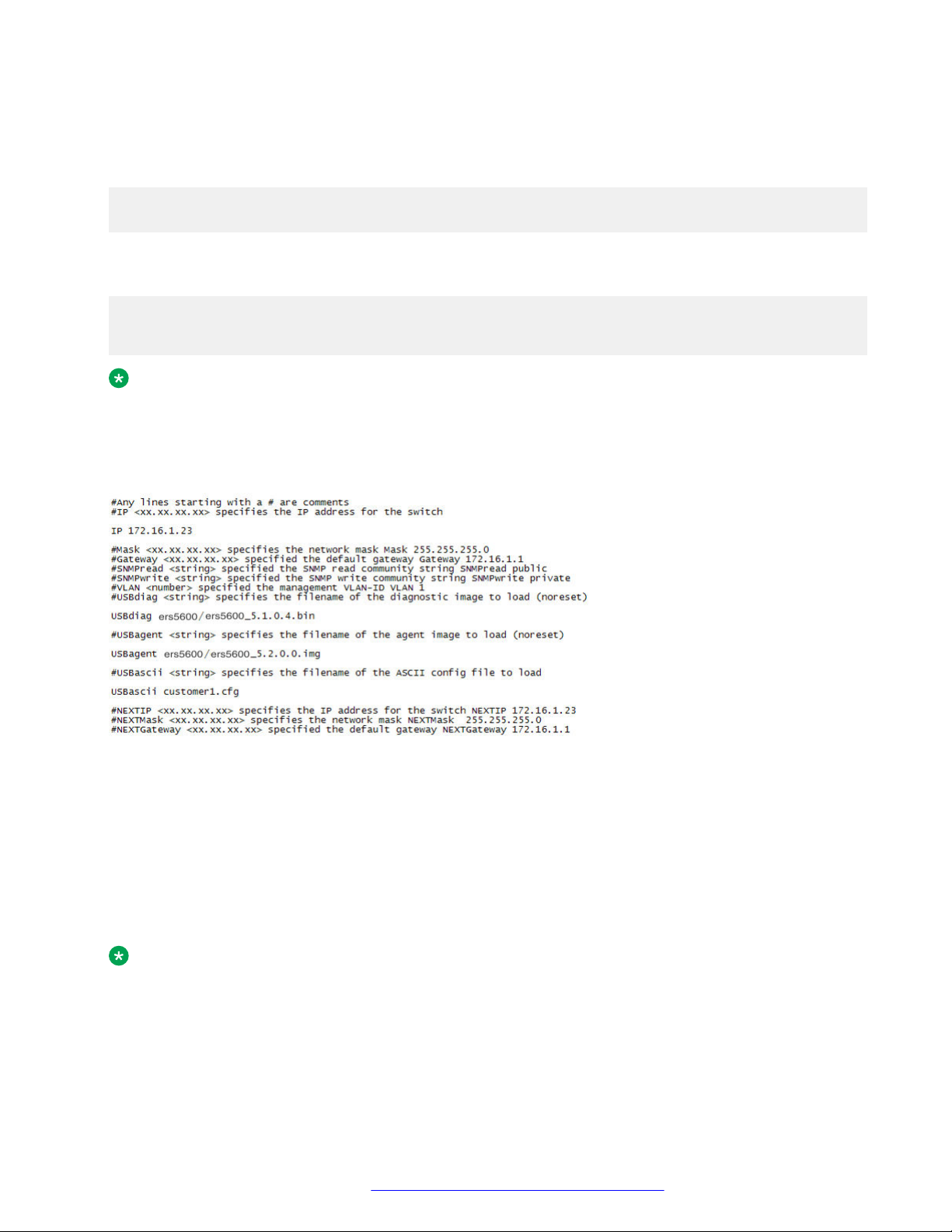
Setting in-band management IP address parameters from the ip.cfg file on a USB device
The ip.cfg file loads information from the ASCII configuration file in order of precedence. For
example, the stack IP becomes 181.30.30.113 no matter what IP address is in the ip.txt file if you
have an ip.cfg file with the following commands:
USBascii ip.txt IP 181.30.30.113
Mask 255.255.255.0
Gateway 181.30.30.254
The stack IP will be the IP address defined in the ip.txt file if you have an ip.cfg file with the
following commands:
IP 181.30.30.113
Mask 255.255.255.0
Gateway 181.30.30.254
USBascii ip.txt
Note:
The ip.cfg file runs only on a base or standalone unit. The file cannot be more than 4096
bytes or contain more than 200 lines.
The following figure shows an example of an ip.cfg file.
Figure 3: ip.cfg file example
If the ip.cfg file specifies an image or agent code, the switch loads the software, even if the same
version is already installed on the switch. Ensuring that the appropriate software is always upgraded
on the units is the correct operation of ip.cfg.
Use the factory default command to reset the switch to the factory default after you insert the USB
memory device in the USB port. The USB memory device must contain the properly formatted
ip.cfg file in the root directory.
Note:
The system does not display a message to indicate the ip.cfg file progress, you need to
connect to the switch after 3 minutes of booting to verify the ip.cfg operation. You can
typically confirm the successful download of ip.cfg by using the ACLI show ip command. If
October 2015 Quick Start Configuration for Avaya ERS 5900 Series 71
Comments on this document? [email protected]
Page 72
Configuring management IP addresses using ACLI
the USB ip.cfg file download succeeded, all parameters read from the file show are present
in the switch and part of the runtime configuration.
Configuring a Domain Name Server
Use this procedure to set the default DNS domain name for the switch.
Note:
This default domain name is appended to all DNS queries or commands that do not already
contain a DNS domain name.
Procedure
1. Log on to the Global Configuration mode in ACLI.
2. At the command prompt, enter the following command:
ip domain-name <DNS_domain name>
Variable definitions
The following table describes the parameters for the ip domain-name command.
Variable
<DNS_domain_name> Specify the default domain name to be used.
Value
The default form of this command is default ip
domain-name.
The no form of this command is no ip domain-name.
Resolving domain names to IP addresses
Use this procedure to set the domain name servers the switch uses to resolve a domain name to an
IP address.
About this task
A switch can have up to three domain name servers specified for this purpose.
Note:
To enter all three server addresses you must enter the command three times, each with a
different server address.
October 2015 Quick Start Configuration for Avaya ERS 5900 Series 72
Comments on this document? [email protected]
Page 73
Clearing the IP address
Procedure
1. Log on to the Global Configuration mode in ACLI.
2. At the command prompt, enter the following command:
ip name-server [<ipv6_address> | <ip_address_1>]
ip name-server [<ipv6_address> | <ip_address_2>]
ip name-server [<ipv6_address> | <ip_address_3>]
Variable definitions
The following table describes the parameters for the ip name-server command.
Note:
The IPv6 parameter is valid only for switches that support IPv6.
Variable Value
ipv6_address The IPv6 address of the domain name server used
by the switch.
ip_address_1 The IP address of the domain name server used by
the switch.
ip_address_2 Optional. The IP address of a domain name server to
add to the list of servers used by the switch.
ip_address_3 Optional. The IP address of a domain name server to
add to the list of servers used by the switch.
no ip name-server [<ipv6_address> |
<ip_address_1>]
no ip name-server [<ipv6_address> |
<ip_address_2>]
The no form of this command removes domain name
servers from the list of servers used by the switch to
resolve domain names to an IP address.
no ip name-server [<ipv6_address> |
<ip_address_3>]
Clearing the IP address
Use this procedure to clear the IPv4 address and subnet mask or IPv6 address for a switch or a
stack.
Note:
When the IP address or subnet mask is changed, connectivity to Telnet can be lost. Any new
Telnet connection can be disabled and is required to connect to the serial console port to
configure a new IP address.
October 2015 Quick Start Configuration for Avaya ERS 5900 Series 73
Comments on this document? [email protected]
Page 74

Configuring management IP addresses using ACLI
About this task
This command sets the IP address and subnet mask for a stack, switch, or unit to all zeros (0).
Procedure
1. Log on to the Global Configuration mode in ACLI.
2. At the command prompt, enter the following command for IPv4 addresses:
no ip address {stack | switch | unit <1–8>}
OR
for IPv6 addresses, enter the following command:
no ipv6 address {stack | switch | unit <1–8>}
Setting the in-band default IP gateway address
Use this procedure to set the default IP gateway address for a switch or a stack.
Note:
When the IP gateway is changed, connectivity to Telnet can be lost.
Important:
Only one management default gateway can operate for each unit or stack. The out-of-band
management default gateway takes precedence over the in-band management default gateway.
Once an out-of-band management default gateway is configured, the in-band management
address is reachable only through a directly attached subnet for the management VLAN.
Procedure
1. Log on to the Global Configuration mode in ACLI.
2. To configure the IPv4 address of the default gateway, enter the following command at the
command prompt:
ip default-gateway <A.B.C.D>
Deleting the in-band default IP gateway address
Use this procedure to delete the default IP gateway address.
Note:
When the IP gateway is changed, connectivity to Telnet can be lost.
October 2015 Quick Start Configuration for Avaya ERS 5900 Series 74
Comments on this document? [email protected]
Page 75

Procedure
1. Log on to the Global Configuration mode in ACLI.
2. At the command prompt, enter the following command:
no ip default-gateway
OR
no ipv6 default-gateway
Deleting the in-band default IP gateway address
October 2015 Quick Start Configuration for Avaya ERS 5900 Series 75
Comments on this document? [email protected]
Page 76

Chapter 6: Configuring management IP
addresses using EDM
This chapter provides procedural information you can use to assign, clear, and view in-band and
out-of-band management IP addresses and gateway IP addresses.
Configuring out-of-band management using EDM
Use this procedure to configure the out-of-band management IP address, subnet mask, and default
gateway.
About this task
When you physically connect Ethernet RJ-45 management port for standalone switch or stack to
your network and assign an IP address to the port, you can use the management port to access the
switch or stack using Telnet, SSH, SNMP, HTTP, and HTTPS.
Note:
The out-of-band management IP address must be different than the switch or stack in-band
management IP address.
Procedure
1. From the navigation pane, double-click Edit.
2. In the Edit tree, click Chassis.
3. In the Chassis tree, click Switch/Stack.
4. In the Switch/Stack work area, click the Management IP tab.
5. To configure out-of-band management parameters for a switch, double-click table cells as
required.
6. On the toolbar, click Apply.
7. On the toolbar, you can click Refresh to verify the out-of-band management configuration.
October 2015 Quick Start Configuration for Avaya ERS 5900 Series 76
Comments on this document? [email protected]
Page 77
Configuring out-of-band management using EDM
Variable definitions
Variable Value
Unit Indicates a stack switch unit, for which to configure
an out-of-band management IP address. Values
range from 1 to 8.
For a stack environment, a Unit value of 1 specifies
the base unit.
For a standalone switch, the Unit value is 1.
IpMgmtAddress Specifies an out-of-band management IP address for
the selected switch.
DEFAULT for IPv4: 0.0.0.0
IpMgmtNetMask Specifies the subnet mask associated with the out-
of-band management IP address.
DEFAULT for IPv4: 0.0.0.0
IpMgmtGateway Specifies the IP address for the out-of-band
management default gateway.
DEFAULT for IPv4: 0.0.0.0
DEFAULT for IPv6: 0:0:0:0:0:0
Important:
If you configure an out-of-band default gateway,
the device disables the in-band default gateway.
The out-of-band management default gateway
takes precedence over the in-band
management default gateway.
Ipv6MgmtAddress Specifies an out-of-band management IP address for
the selected switch.
Specifies the IPv6 address associated with the
physical dedicated out-of-band management port of
a component. For a stackable system in stack mode,
this IPv6 address always applies to the individual
units in the stack.
DEFAULT for IPv6: 0::0/0
Ipv6MgmtNetMask Specifies the subnet mask associated with the out-
of-bank management IP address.
Specifies the IPv6 address associated with the
physical dedicated out-of-band management port of
a component. For a stackable system in stack mode,
this netmask always applies to the individual units in
the stack.
Table continues…
October 2015 Quick Start Configuration for Avaya ERS 5900 Series 77
Comments on this document? [email protected]
Page 78

Configuring management IP addresses using EDM
Variable Value
DEFAULT for IPv6: 0::0/0
IpMgmtShutdown Specifies whether to enable or disable the
management port for the unit. A value of true
disables the port.
DEFAULT: false
October 2015 Quick Start Configuration for Avaya ERS 5900 Series 78
Comments on this document? [email protected]
Page 79

Chapter 7: Verification
This chapter contains information about how to verify that your provisioning procedures result in a
functional switch.
Pinging an IP device
You can ping a device to test the connection between a switch and another network device. After
you ping a device, the switch sends an Internet Control Message Protocol (ICMP) packet to the
target device. If the device receives the packet, it sends a ping reply. After the switch receives the
reply, a message appears that indicates traffic can reach the specified IP address. If the switch does
not receive a reply, the message indicates the address does not respond.
About this task
Use this procedure to ping a device.
Procedure
1. Log on to ACLI to enter User EXEC mode.
2. At the command prompt, enter the following command:
ping <IP_address>
where <IP_address> is an IPv4 or IPv6 address.
Verifying the software release
About this task
Use this procedure to display the currently-loaded and operational software load
Procedure
1. Log on to ACLI to enter User EXEC mode.
2. At the command prompt, enter the following command:
show boot [diag | image [primary | secondary]]
October 2015 Quick Start Configuration for Avaya ERS 5900 Series 79
Comments on this document? [email protected]
Page 80
Verification
Example
The following displays the output from the show boot command.
Switch#show boot
Unit Agent Image Secondary Image Active Image Diag Image Active Diag
----- ----------- --------------- ------------ ---------- ----------1 7.0.0.066 7.0.0.042 7.0.0.066 0.0.0.2c 0.0.0.2c
* - Unit requires reboot for new Active Image to be made operational.
# - Unit requires reboot for new Diag to be made operational.
Switch#show boot diag
Unit Diag Image Active Diag
----- ---------- ----------1 0.0.0.2c 0.0.0.2c
# - Unit requires reboot for new Diag to be made operational.
Switch#show boot image
Unit Agent Image Secondary Image Active Image
----- ----------- --------------- -----------1 7.0.0.066 7.0.0.042 7.0.0.066
* - Unit requires reboot for new Active Image to be made operational.
Switch#show boot image primary
Unit Agent Image Active Image
----- ----------- -----------1 7.0.0.163 7.0.0.163
* - Unit requires reboot for new Active Image to be made operational.
Variable definitions
Use the definitions in the following table to use the show boot command.
Variable Definition
diag Displays only information for the agent load.
image [primary |
secondary]
Displays information about the image load. Options are:
• primary—display primary image software version.
• secondary—display secondary image software version.
Important:
When the currently loaded and operational software status is displayed for a stack, the unit
number is replaced by the word All.
Displaying local alarms
You can view local alarms to monitor alarm conditions.
Local alarms are raised and cleared by applications running on the switch. Local alarms are an
automatic mechanism run by the system and do not require any additional user configuration. The
October 2015 Quick Start Configuration for Avaya ERS 5900 Series 80
Comments on this document? [email protected]
Page 81

Displaying local alarms
raising and clearing of local alarms also creates a log entry for each event. Check alarms
occasionally to ensure no alarms require additional operator attention.
About this task
Use this procedure to display local alarms.
Procedure
1. Enter Global Configuration mode:
enable
configure terminal
2. At the command prompt, enter the following command :
show rmon alarm
October 2015 Quick Start Configuration for Avaya ERS 5900 Series 81
Comments on this document? [email protected]
 Loading...