

Page 1

Avaya Application Solutions:
IP Telephony Deployment Guide
555-245-600
Issue 6
January 2008
Page 2

© 2008 Avaya Inc.
All Rights Reserved.
Notice
While reasonable efforts were made to ensure that the information in this
document was complete and accurate at the time of printing, Avaya Inc. can
assume no liability for any errors. Changes and corrections to the information
in this document may be incorporated in future releases.
For full legal page information, please see the documents,
Avaya Support Notices for Software Documentation, 03-600758, and
Avaya Support Notices for Hardware Documentation, 03-600759.
These documents can be accessed on the documentation CD and on the
Web site, http://www.avaya.com/support
document number in the Search box.
Documentation disclaimer
Avaya Inc. is not responsible for any modifications, additions, or deletions to
the original published version of this documentation unless such modifications,
additions, or deletions were performed by Avaya. Customer and/or End User
agree to indemnify and hold harmless Avaya, Avaya's agents, servants and
employees against all claims, lawsuits, demands and judgments arising out of,
or in connection with, subsequent modifications, additions or deletions to this
documentation to the extent made by the Customer or End User.
Link disclaimer
Avaya Inc. is not responsible for the contents or reliability of any linked Web
sites referenced elsewhere within this documentation, and Avaya does not
necessarily endorse the products, services, or information described or offered
within them. We cannot guarantee that these links will work all of the time and
we have no control over the availability of the linked pages.
Warr anty
Avaya Inc. provides a limited warranty on this product. Refer to your sales
agreement to establish the terms of the limited warranty. In addition, Avaya’s
standard warranty language, as well as information regarding support for this
product, while under warranty, is available through the following Web site:
http://www.avaya.com/support
Copyright
Except where expressly stated otherwise, the Product is protected by copyright
and other laws respecting proprietary rights. Unauthorized reproduction,
transfer, and or use can be a criminal, as well as a civil, offense under the
applicable law.
Avaya support
Avaya provides a telephone number for you to use to report problems or to ask
questions about your product. The support telephone number
is 1-800-242-2121 in the United States. For additional support telephone
numbers, see the Avaya Web site: http://www.avaya.com/support
.
. On the Web site, search for the
.
Page 3

Contents
About This Book. . . . . . . . . . . . . . . . . . . . . . . . . . . . . . . 11
Overview . . . . . . . . . . . . . . . . . . . . . . . . . . . . . . . . . . . . . . . . 11
Audience . . . . . . . . . . . . . . . . . . . . . . . . . . . . . . . . . . . . . . . . 11
Using this book . . . . . . . . . . . . . . . . . . . . . . . . . . . . . . . . . . . . 11
Downloading this book and updates from the Web . . . . . . . . . . . . . . . . . 12
Related resources . . . . . . . . . . . . . . . . . . . . . . . . . . . . . . . . . . . 13
Technical assistance . . . . . . . . . . . . . . . . . . . . . . . . . . . . . . . . . 13
Within the US. . . . . . . . . . . . . . . . . . . . . . . . . . . . . . . . . . . . 13
International . . . . . . . . . . . . . . . . . . . . . . . . . . . . . . . . . . . . 13
Trademarks. . . . . . . . . . . . . . . . . . . . . . . . . . . . . . . . . . . . . . . 14
Sending us comments. . . . . . . . . . . . . . . . . . . . . . . . . . . . . . . . . 14
Section 1: Avaya Application Solutions
product guide . . . . . . . . . . . . . . . . . . . . . . . 15
Avaya Application Solutions . . . . . . . . . . . . . . . . . . . . . . . . 17
Avaya Communication Manager . . . . . . . . . . . . . . . . . . . . . . . . . . . 19
Avaya servers . . . . . . . . . . . . . . . . . . . . . . . . . . . . . . . . . . . 19
Avaya Media Gateways . . . . . . . . . . . . . . . . . . . . . . . . . . . . . . 20
Avaya Integrated Management . . . . . . . . . . . . . . . . . . . . . . . . . . 20
Avaya communication devices . . . . . . . . . . . . . . . . . . . . . . . . . . 21
Avaya Communication Manager applications . . . . . . . . . . . . . . . . . . 21
Avaya SIP solutions . . . . . . . . . . . . . . . . . . . . . . . . . . . . . . . . 22
Avaya SIP application enablement . . . . . . . . . . . . . . . . . . . . . . . . 22
Avaya Distributed Office . . . . . . . . . . . . . . . . . . . . . . . . . . . . . . . 23
Distributed Office Configurations . . . . . . . . . . . . . . . . . . . . . . . . 24
Distributed Office benefits . . . . . . . . . . . . . . . . . . . . . . . . . . . . 26
Distributed Office implementation . . . . . . . . . . . . . . . . . . . . . . . . 26
Streamlined Deployment . . . . . . . . . . . . . . . . . . . . . . . . . . . . . 30
Avaya Application Solutions platforms . . . . . . . . . . . . . . . . . . 33
Overview . . . . . . . . . . . . . . . . . . . . . . . . . . . . . . . . . . . . . . . . 33
Terminology . . . . . . . . . . . . . . . . . . . . . . . . . . . . . . . . . . . . 36
Small to mid-size enterprise . . . . . . . . . . . . . . . . . . . . . . . . . . . . . 37
Avaya S8300 Server and Avaya G700, G450,
G350, or G250 Media Gateway. . . . . . . . . . . . . . . . . . . . . . . . . . 37
G450 Media Gateway . . . . . . . . . . . . . . . . . . . . . . . . . . . . . . . 43
G250 and G350 Media Gateways . . . . . . . . . . . . . . . . . . . . . . . . . 52
G150 Media Gateway . . . . . . . . . . . . . . . . . . . . . . . . . . . . . . . 61
Issue 6 January 2008 3
Page 4

IG550 Integrated Gateway . . . . . . . . . . . . . . . . . . . . . . . . . . . . 62
TGM550 physical description . . . . . . . . . . . . . . . . . . . . . . . . . . . 69
Avaya S8400 Server . . . . . . . . . . . . . . . . . . . . . . . . . . . . . . . . 75
Mid-market to large enterprise . . . . . . . . . . . . . . . . . . . . . . . . . . . . 79
S8500 Server . . . . . . . . . . . . . . . . . . . . . . . . . . . . . . . . . . . 79
Avaya S8700-series Server, fiber-PNC configuration . . . . . . . . . . . . . . 79
Avaya S8700-series Server IP-PNC configuration . . . . . . . . . . . . . . . . 96
Combined IP and fiber Port Network Connectivity . . . . . . . . . . . . . . . 102
Processor Ethernet . . . . . . . . . . . . . . . . . . . . . . . . . . . . . . . . . . 107
Avaya IP Office. . . . . . . . . . . . . . . . . . . . . . . . . . . . . . . . . . . 108
Greenfield deployment . . . . . . . . . . . . . . . . . . . . . . . . . . . 109
Components needed for Greenfield deployment . . . . . . . . . . . . . . . . . . 109
Servers (H.323 Gatekeeper) . . . . . . . . . . . . . . . . . . . . . . . . . . . . 110
Avaya Communication Manager . . . . . . . . . . . . . . . . . . . . . . . . . 111
Media Gateways and Port Networks . . . . . . . . . . . . . . . . . . . . . . . 111
Greenfield configurations . . . . . . . . . . . . . . . . . . . . . . . . . . . . . . . 112
S8300 standalone solution
(small-to-midsize enterprise) . . . . . . . . . . . . . . . . . . . . . . . . . . 112
Medium-to-large enterprise solutions . . . . . . . . . . . . . . . . . . . . . . 113
Required circuit packs for S8700-series configuration . . . . . . . . . . . . . 116
Evolution from circuit-switched to IP . . . . . . . . . . . . . . . . . . . 119
Overview . . . . . . . . . . . . . . . . . . . . . . . . . . . . . . . . . . . . . . . . 119
Migration from DEFINITY
Server R to S8700 fiber-PNC. . . . . . . . . . . . . . . . . . . . . . . . . . . . . 120
Phase 1: Processor replacement . . . . . . . . . . . . . . . . . . . . . . . . . 120
Phase 2: IP-enable the Port Networks to support IP endpoints . . . . . . . . 122
Phase 3: Server consolidation . . . . . . . . . . . . . . . . . . . . . . . . . . 123
Call processing . . . . . . . . . . . . . . . . . . . . . . . . . . . . . . . 125
Voice and multimedia networking . . . . . . . . . . . . . . . . . . . . . . . . . . 125
Intelligent networking and call routing . . . . . . . . . . . . . . . . . . . . . . 125
IP Port Network / Media Gateway connectivity . . . . . . . . . . . . . . . . . 126
H.248 Media Gateway control . . . . . . . . . . . . . . . . . . . . . . . . . . . 126
Call Processing . . . . . . . . . . . . . . . . . . . . . . . . . . . . . . . . . . . . 127
Communication Manager gatekeepers . . . . . . . . . . . . . . . . . . . . . . 127
Call signaling. . . . . . . . . . . . . . . . . . . . . . . . . . . . . . . . . . . . 128
Media stream handling . . . . . . . . . . . . . . . . . . . . . . . . . . . . . . 129
Separation of Bearer and Signaling (SBS) . . . . . . . . . . . . . . . . . . . . 130
4 Avaya Application Solutions IP Telephony Deployment Guide
Page 5

Multi-location. . . . . . . . . . . . . . . . . . . . . . . . . . . . . . . . . . . . 131
Modem/Fax/TTY over IP . . . . . . . . . . . . . . . . . . . . . . . . . . . . . . 131
IP-based trunks . . . . . . . . . . . . . . . . . . . . . . . . . . . . . . . . . . . . 133
IP tie trunks . . . . . . . . . . . . . . . . . . . . . . . . . . . . . . . . . . . . 134
Trunk signaling . . . . . . . . . . . . . . . . . . . . . . . . . . . . . . . . . . 134
SIP . . . . . . . . . . . . . . . . . . . . . . . . . . . . . . . . . . . . . . . . . . . 134
Avaya SIP Enablement Services (SES). . . . . . . . . . . . . . . . . . . . . . 135
Communication Manager as the SIP Feature Server . . . . . . . . . . . . . . 137
SIP Adjuncts . . . . . . . . . . . . . . . . . . . . . . . . . . . . . . . . . . . . 138
SIP Endpoints . . . . . . . . . . . . . . . . . . . . . . . . . . . . . . . . . . . 138
SIP deployment scenarios . . . . . . . . . . . . . . . . . . . . . . . . . . . . 139
Avaya G860 Media Gateway. . . . . . . . . . . . . . . . . . . . . . . . . . . . . . 147
G860 Components . . . . . . . . . . . . . . . . . . . . . . . . . . . . . . . . . 149
Configuration with Avaya Communication Manager . . . . . . . . . . . . . . 150
Mobility . . . . . . . . . . . . . . . . . . . . . . . . . . . . . . . . . . . . . . . . . 152
IP Telephones or IP Softphones . . . . . . . . . . . . . . . . . . . . . . . . . 152
Extension to Cellular . . . . . . . . . . . . . . . . . . . . . . . . . . . . . . . 152
Communication applications . . . . . . . . . . . . . . . . . . . . . . . . . . . . . 152
Call Center . . . . . . . . . . . . . . . . . . . . . . . . . . . . . . . . . . . . . 153
Messaging . . . . . . . . . . . . . . . . . . . . . . . . . . . . . . . . . . . . . 154
Unified Communication Center . . . . . . . . . . . . . . . . . . . . . . . . . . 155
Avaya Call Management System (CMS) . . . . . . . . . . . . . . . . . . . . . 155
Conferencing systems . . . . . . . . . . . . . . . . . . . . . . . . . . . . . . 155
Meet-me conferencing. . . . . . . . . . . . . . . . . . . . . . . . . . . . . . . 155
Avaya Meeting Exchange Solutions . . . . . . . . . . . . . . . . . . . . . . . 156
Computer Telephony Integration (CTI) . . . . . . . . . . . . . . . . . . . . . . 160
Application Programming Interfaces (APIs) . . . . . . . . . . . . . . . . . . . 160
Best Services Routing (BSR) polling . . . . . . . . . . . . . . . . . . . . . . . 161
LAN switching products . . . . . . . . . . . . . . . . . . . . . . . . . . 163
Avaya C360 converged stackable switches . . . . . . . . . . . . . . . . . . . . . 163
Features of the C360 converged stackable switches . . . . . . . . . . . . . . 164
Switches from Extreme Networks . . . . . . . . . . . . . . . . . . . . . . . . 167
Avaya Power over Ethernet (PoE) switches . . . . . . . . . . . . . . . . . . . 168
Midspan Power Units . . . . . . . . . . . . . . . . . . . . . . . . . . . . . . . . . 169
1152A1 Power Distribution Unit . . . . . . . . . . . . . . . . . . . . . . . . . 169
1152B Power Distribution Units . . . . . . . . . . . . . . . . . . . . . . . . . 171
Converged infrastructure security gateways . . . . . . . . . . . . . . . . . . . . 172
VPN Client . . . . . . . . . . . . . . . . . . . . . . . . . . . . . . . . . . . . . . . 172
Issue 6 January 2008 5
Page 6

Section 2: Deploying IP Telephony . . . . . . . . . . . . . . . . . . 175
Traffic engineering . . . . . . . . . . . . . . . . . . . . . . . . . . . . . 177
Introduction . . . . . . . . . . . . . . . . . . . . . . . . . . . . . . . . . . . . . . 177
Design inputs . . . . . . . . . . . . . . . . . . . . . . . . . . . . . . . . . . . . . 178
Topology . . . . . . . . . . . . . . . . . . . . . . . . . . . . . . . . . . . . . . 178
Endpoint specifications . . . . . . . . . . . . . . . . . . . . . . . . . . . . . . 180
Endpoint traffic usage . . . . . . . . . . . . . . . . . . . . . . . . . . . . . . . 180
Call usage rates . . . . . . . . . . . . . . . . . . . . . . . . . . . . . . . . . . . . 183
Communities of interest. . . . . . . . . . . . . . . . . . . . . . . . . . . . . . 183
Expanded COI matrices . . . . . . . . . . . . . . . . . . . . . . . . . . . . . . 191
COIs for multiple-site networks. . . . . . . . . . . . . . . . . . . . . . . . . . 197
Resource sizing . . . . . . . . . . . . . . . . . . . . . . . . . . . . . . . . . . . . 198
Overview . . . . . . . . . . . . . . . . . . . . . . . . . . . . . . . . . . . . . . 198
Signaling resources . . . . . . . . . . . . . . . . . . . . . . . . . . . . . . . . 199
Media processing and TDM resources . . . . . . . . . . . . . . . . . . . . . . 200
Processing occupancy . . . . . . . . . . . . . . . . . . . . . . . . . . . . . . 211
SIP traffic engineering. . . . . . . . . . . . . . . . . . . . . . . . . . . . . . . 213
IP bandwidth and Call Admission Control . . . . . . . . . . . . . . . . . . . . 216
Physical resource placement . . . . . . . . . . . . . . . . . . . . . . . . . . . 224
Final checks and adjustments . . . . . . . . . . . . . . . . . . . . . . . . . . 224
Avaya Distributed Office . . . . . . . . . . . . . . . . . . . . . . . . . . . . . . . 225
Security . . . . . . . . . . . . . . . . . . . . . . . . . . . . . . . . . . 227
Your security policy . . . . . . . . . . . . . . . . . . . . . . . . . . . . . . . . . . 227
Avaya Communication
Manager and Servers. . . . . . . . . . . . . . . . . . . . . . . . . . . . . . . . . 229
LAN isolation configurations . . . . . . . . . . . . . . . . . . . . . . . . . . . 233
Virus and worm protection . . . . . . . . . . . . . . . . . . . . . . . . . . . . 236
IP Telephony circuit pack security . . . . . . . . . . . . . . . . . . . . . . . . . . 238
TN2312BP IP Server Interface (IPSI) . . . . . . . . . . . . . . . . . . . . . . . 238
TN2302AP and TN2602AP Media Processors . . . . . . . . . . . . . . . . . . 239
TN799DP Control LAN (C-LAN) . . . . . . . . . . . . . . . . . . . . . . . . . . 240
Toll fraud . . . . . . . . . . . . . . . . . . . . . . . . . . . . . . . . . . . . . . . . 240
Avaya’s security design . . . . . . . . . . . . . . . . . . . . . . . . . . . . . . 241
Hacking methods . . . . . . . . . . . . . . . . . . . . . . . . . . . . . . . . . 241
Your toll fraud responsibilities . . . . . . . . . . . . . . . . . . . . . . . . . . 242
Toll fraud indemnification . . . . . . . . . . . . . . . . . . . . . . . . . . . . . 242
Additional toll fraud resources . . . . . . . . . . . . . . . . . . . . . . . . . . 242
6 Avaya Application Solutions IP Telephony Deployment Guide
Page 7

Voice quality network requirements . . . . . . . . . . . . . . . . . . . . 245
Network delay . . . . . . . . . . . . . . . . . . . . . . . . . . . . . . . . . . . . . 245
Codec delay . . . . . . . . . . . . . . . . . . . . . . . . . . . . . . . . . . . . 246
Jitter . . . . . . . . . . . . . . . . . . . . . . . . . . . . . . . . . . . . . . . . . . 247
Packet loss . . . . . . . . . . . . . . . . . . . . . . . . . . . . . . . . . . . . . . . 247
Network packet loss . . . . . . . . . . . . . . . . . . . . . . . . . . . . . . . . 248
Packet loss concealment (PLC). . . . . . . . . . . . . . . . . . . . . . . . . . 249
Echo . . . . . . . . . . . . . . . . . . . . . . . . . . . . . . . . . . . . . . . . . . 249
Signal levels . . . . . . . . . . . . . . . . . . . . . . . . . . . . . . . . . . . . . . 250
Echo and Signal Levels . . . . . . . . . . . . . . . . . . . . . . . . . . . . . . 251
Tone Levels . . . . . . . . . . . . . . . . . . . . . . . . . . . . . . . . . . . . 251
Codecs . . . . . . . . . . . . . . . . . . . . . . . . . . . . . . . . . . . . . . . . . 251
G.726 Codec and H.248 Media Gateways . . . . . . . . . . . . . . . . . . . . 253
Silence suppression/VAD . . . . . . . . . . . . . . . . . . . . . . . . . . . . . . . 253
Transcoding/tandeming . . . . . . . . . . . . . . . . . . . . . . . . . . . . . . . . 254
CNA Application Performance Rating . . . . . . . . . . . . . . . . . . . . . . . . 254
Translating low level statistics to an Application Performance rating . . . . . . . 255
Available application models . . . . . . . . . . . . . . . . . . . . . . . . . . . 256
Avaya Integrated Management . . . . . . . . . . . . . . . . . . . . . . . 257
Integrated Management overview documents. . . . . . . . . . . . . . . . . . . . 257
Avaya Integrated Management offers . . . . . . . . . . . . . . . . . . . . . . . . 257
Administration Tools Offer . . . . . . . . . . . . . . . . . . . . . . . . . . . . 258
VoIP Monitoring Management Offer . . . . . . . . . . . . . . . . . . . . . . . 258
Enterprise Network Management Offer . . . . . . . . . . . . . . . . . . . . . 259
System Management Offer . . . . . . . . . . . . . . . . . . . . . . . . . . . . 259
Third-party network management products . . . . . . . . . . . . . . . . . . . . . 260
Multi Router Traffic Grapher . . . . . . . . . . . . . . . . . . . . . . . . . . . 260
HP OpenView Network Node Manager . . . . . . . . . . . . . . . . . . . . . . 261
Network management models . . . . . . . . . . . . . . . . . . . . . . . . . . . . 261
Distributed (component) . . . . . . . . . . . . . . . . . . . . . . . . . . . . . 262
Centralized (hybrid) . . . . . . . . . . . . . . . . . . . . . . . . . . . . . . . . 262
Reliability and Recovery . . . . . . . . . . . . . . . . . . . . . . . . . . 265
Reliability. . . . . . . . . . . . . . . . . . . . . . . . . . . . . . . . . . . . . . . . 266
Survivability solutions. . . . . . . . . . . . . . . . . . . . . . . . . . . . . . . . . 267
S8700-series Server Separation . . . . . . . . . . . . . . . . . . . . . . . . . 268
Enterprise survivable servers (ESS) . . . . . . . . . . . . . . . . . . . . . . . 269
Issue 6 January 2008 7
Page 8

Connection preserving upgrades for duplex servers . . . . . . . . . . . . . . 271
Inter Gateway Alternate Routing (IGAR) . . . . . . . . . . . . . . . . . . . . . 271
Survivability for branch office media gateways . . . . . . . . . . . . . . . . . . . 272
H.248 Media Gateway recovery via LSP . . . . . . . . . . . . . . . . . . . . . 272
Modem dial-up backup . . . . . . . . . . . . . . . . . . . . . . . . . . . . . . 273
Auto fallback to primary Communication Manager for H.248 media gateways 273
Connection preserving failover/failback for H.248 media gateways . . . . . . 274
G250 and IG550 Media Gateway standard local survivability function (SLS) . 274
IP endpoint recovery . . . . . . . . . . . . . . . . . . . . . . . . . . . . . . . . . 275
IP endpoint recovery . . . . . . . . . . . . . . . . . . . . . . . . . . . . . . . 275
Recovery algorithm . . . . . . . . . . . . . . . . . . . . . . . . . . . . . . . . 276
IP Endpoint Time to Service . . . . . . . . . . . . . . . . . . . . . . . . . . . 277
Converged Network Analyzer for network optimization . . . . . . . . . . . . 278
Section 3: Getting the IP network ready for telephony . . . . . . . 281
IP Telephony network engineering overview . . . . . . . . . . . . . . . 283
Overview . . . . . . . . . . . . . . . . . . . . . . . . . . . . . . . . . . . . . . . . 283
Voice quality . . . . . . . . . . . . . . . . . . . . . . . . . . . . . . . . . . . . . . 285
Best practices . . . . . . . . . . . . . . . . . . . . . . . . . . . . . . . . . . . . . 287
Common issues . . . . . . . . . . . . . . . . . . . . . . . . . . . . . . . . . . . . 288
Network design . . . . . . . . . . . . . . . . . . . . . . . . . . . . . . . 289
LAN issues . . . . . . . . . . . . . . . . . . . . . . . . . . . . . . . . . . . . . . . 289
General guidelines. . . . . . . . . . . . . . . . . . . . . . . . . . . . . . . . . 289
VLANs . . . . . . . . . . . . . . . . . . . . . . . . . . . . . . . . . . . . . . . 291
WAN. . . . . . . . . . . . . . . . . . . . . . . . . . . . . . . . . . . . . . . . . . . 293
Overview . . . . . . . . . . . . . . . . . . . . . . . . . . . . . . . . . . . . . . 294
Frame Relay . . . . . . . . . . . . . . . . . . . . . . . . . . . . . . . . . . . . 296
MPLS . . . . . . . . . . . . . . . . . . . . . . . . . . . . . . . . . . . . . . . . 298
VPN . . . . . . . . . . . . . . . . . . . . . . . . . . . . . . . . . . . . . . . . . . . 299
Convergence advantages . . . . . . . . . . . . . . . . . . . . . . . . . . . . . 299
Managing IP Telephony VPN issues . . . . . . . . . . . . . . . . . . . . . . . 300
Conclusion . . . . . . . . . . . . . . . . . . . . . . . . . . . . . . . . . . . . . 302
NAT . . . . . . . . . . . . . . . . . . . . . . . . . . . . . . . . . . . . . . . . . . . 302
Converged network design . . . . . . . . . . . . . . . . . . . . . . . . . . . . . . 304
Design and Management . . . . . . . . . . . . . . . . . . . . . . . . . . . . . 304
Design for Simplicity . . . . . . . . . . . . . . . . . . . . . . . . . . . . . . . 304
Design for Manageability . . . . . . . . . . . . . . . . . . . . . . . . . . . . . 305
8 Avaya Application Solutions IP Telephony Deployment Guide
Page 9

Design for Scalability . . . . . . . . . . . . . . . . . . . . . . . . . . . . . . . 305
Topologies . . . . . . . . . . . . . . . . . . . . . . . . . . . . . . . . . . . . . 306
Server Cluster . . . . . . . . . . . . . . . . . . . . . . . . . . . . . . . . . . . 306
Layers . . . . . . . . . . . . . . . . . . . . . . . . . . . . . . . . . . . . . . . 307
Redundancy . . . . . . . . . . . . . . . . . . . . . . . . . . . . . . . . . . . . 308
Layer 2 . . . . . . . . . . . . . . . . . . . . . . . . . . . . . . . . . . . . . . . 310
Layer 3 . . . . . . . . . . . . . . . . . . . . . . . . . . . . . . . . . . . . . . . 312
Quality of Service guidelines . . . . . . . . . . . . . . . . . . . . . . . . 315
CoS . . . . . . . . . . . . . . . . . . . . . . . . . . . . . . . . . . . . . . . . . . . 315
Layer 2 QoS . . . . . . . . . . . . . . . . . . . . . . . . . . . . . . . . . . . . . . 317
Layer 3 QoS . . . . . . . . . . . . . . . . . . . . . . . . . . . . . . . . . . . . . . 317
QoS guidelines. . . . . . . . . . . . . . . . . . . . . . . . . . . . . . . . . . . 318
IEEE 802.1 p/Q . . . . . . . . . . . . . . . . . . . . . . . . . . . . . . . . . . . . . 320
Recommendations for end-to-end QoS . . . . . . . . . . . . . . . . . . . . . 321
DiffServ . . . . . . . . . . . . . . . . . . . . . . . . . . . . . . . . . . . . . . . . . 321
RSVP . . . . . . . . . . . . . . . . . . . . . . . . . . . . . . . . . . . . . . . . . . 323
Queuing methods . . . . . . . . . . . . . . . . . . . . . . . . . . . . . . . . . . . 324
WFQ. . . . . . . . . . . . . . . . . . . . . . . . . . . . . . . . . . . . . . . . . 324
PQ. . . . . . . . . . . . . . . . . . . . . . . . . . . . . . . . . . . . . . . . . . 324
Round-robin . . . . . . . . . . . . . . . . . . . . . . . . . . . . . . . . . . . . 324
CB-WFQ / LLQ / CBQ . . . . . . . . . . . . . . . . . . . . . . . . . . . . . . . 325
RED / WRED . . . . . . . . . . . . . . . . . . . . . . . . . . . . . . . . . . . . 325
Traffic shaping and policing . . . . . . . . . . . . . . . . . . . . . . . . . . . . . 326
Frame Relay traffic shaping. . . . . . . . . . . . . . . . . . . . . . . . . . . . 326
Fragmentation . . . . . . . . . . . . . . . . . . . . . . . . . . . . . . . . . . . . . 327
MTU . . . . . . . . . . . . . . . . . . . . . . . . . . . . . . . . . . . . . . . . . 327
LFI. . . . . . . . . . . . . . . . . . . . . . . . . . . . . . . . . . . . . . . . . . 328
FRF.12 . . . . . . . . . . . . . . . . . . . . . . . . . . . . . . . . . . . . . . . 328
RTP . . . . . . . . . . . . . . . . . . . . . . . . . . . . . . . . . . . . . . . . . . . 328
Application perspective . . . . . . . . . . . . . . . . . . . . . . . . . . . . . . 328
Network perspective. . . . . . . . . . . . . . . . . . . . . . . . . . . . . . . . 329
RTP header compression test . . . . . . . . . . . . . . . . . . . . . . . . . . 330
Configuration . . . . . . . . . . . . . . . . . . . . . . . . . . . . . . . . . . . 331
Examples of QoS implementation . . . . . . . . . . . . . . . . . . . . . . . . . . 332
Example 1: Cisco router configuration for point-to-point WAN links . . . . . 332
Example 2: C-LANS cannot tag their traffic . . . . . . . . . . . . . . . . . . . 335
Example 3: More restrictions on the traffic . . . . . . . . . . . . . . . . . . . 336
Converged infrastructure LAN switches . . . . . . . . . . . . . . . . . . . . . 337
Issue 6 January 2008 9
Page 10

Network recovery . . . . . . . . . . . . . . . . . . . . . . . . . . . . . . 339
Change control. . . . . . . . . . . . . . . . . . . . . . . . . . . . . . . . . . . . . 339
Layer 2 mechanisms to increase reliability . . . . . . . . . . . . . . . . . . . . . 340
Spanning tree . . . . . . . . . . . . . . . . . . . . . . . . . . . . . . . . . . . 340
Link Aggregation Groups . . . . . . . . . . . . . . . . . . . . . . . . . . . . . 340
Layer 3 availability mechanisms . . . . . . . . . . . . . . . . . . . . . . . . . . . 341
Routing protocols . . . . . . . . . . . . . . . . . . . . . . . . . . . . . . . . . 341
VRRP and HSRP . . . . . . . . . . . . . . . . . . . . . . . . . . . . . . . . . . 341
Multipath routing. . . . . . . . . . . . . . . . . . . . . . . . . . . . . . . . . . 342
Dial backup. . . . . . . . . . . . . . . . . . . . . . . . . . . . . . . . . . . . . . . 342
Convergence times . . . . . . . . . . . . . . . . . . . . . . . . . . . . . . . . . . 343
The Converged Network Analyzer . . . . . . . . . . . . . . . . . . . . . . . . . . 344
CNA components . . . . . . . . . . . . . . . . . . . . . . . . . . . . . . . . . 346
Configuration and deployment details . . . . . . . . . . . . . . . . . . . . . . 348
Network assessment offer . . . . . . . . . . . . . . . . . . . . . . . . . 349
Problems with data networks . . . . . . . . . . . . . . . . . . . . . . . . . . . . . 349
Avaya network readiness assessment services. . . . . . . . . . . . . . . . . . . 349
Basic network readiness assessment service. . . . . . . . . . . . . . . . . . 350
Detailed network readiness assessment service . . . . . . . . . . . . . . . . 352
Appendix A: CNA configuration and deployment . . . . . . . . . . . . . 359
Configuring CNA. . . . . . . . . . . . . . . . . . . . . . . . . . . . . . . . . . . . 360
Basic configuration . . . . . . . . . . . . . . . . . . . . . . . . . . . . . . . . 360
Measurements . . . . . . . . . . . . . . . . . . . . . . . . . . . . . . . . . . . 362
Decision making . . . . . . . . . . . . . . . . . . . . . . . . . . . . . . . . . . 363
Configuring the Routers. . . . . . . . . . . . . . . . . . . . . . . . . . . . . . . . 364
Edge Router GRE Tunnel Interfaces . . . . . . . . . . . . . . . . . . . . . . . 364
Route Maps. . . . . . . . . . . . . . . . . . . . . . . . . . . . . . . . . . . . . 365
Routing Configuration. . . . . . . . . . . . . . . . . . . . . . . . . . . . . . . 366
Command summary . . . . . . . . . . . . . . . . . . . . . . . . . . . . . . . . . . 368
CNA commands . . . . . . . . . . . . . . . . . . . . . . . . . . . . . . . . . . 368
Router Ra commands . . . . . . . . . . . . . . . . . . . . . . . . . . . . . . . 370
Router Rb commands . . . . . . . . . . . . . . . . . . . . . . . . . . . . . . . 371
Index . . . . . . . . . . . . . . . . . . . . . . . . . . . . . . . . . . 373
10 Avaya Application Solutions IP Telephony Deployment Guide
Page 11

About This Book
Overview
This book, Avaya Application Solutions IP Telephony Deployment Guide, 555-245-600,
describes Avaya’s Application Solutions product line, IP Telephony product deployment, and
network requirements for integrating IP Telephony products with an IP network. The guide can
be used as a tool to provide a better understanding of the benefits of Avaya IP solutions and of
the many aspects of deploying IP Telephony on a customer’s data network.
This book does not contain procedural information for installing, configuring, or maintaining IP
telephony products. This type of procedural information is contained in other product
documentation available at http://www.avaya.com/support
Audience
.
The primary audiences for this book are:
● Avaya employees and Business Partners working in sales and sales-support
organizations.
● Customers considering the purchase of Avaya’s IP Telephony products.
● Avaya customers who have purchased IP Telephony products and are seeking
suggestions for their implementation.
Secondary audiences include the Technical Service Center (TSC), training, and development.
Using this book
This book is organized in three major sections:
Section I - Avaya Application Solutions product guide. Use this section to learn about Avaya’s
IP Telephony products including:
● Communication Manager
● Servers and gateways and their configurations and capacities
● Migration from circuit-switched to packet-switched products
Issue 6 January 2008 11
Page 12

About This Book
● Call processing features
● LAN switching products
Section II - Deploying IP Telephony. Use this section to learn about deployment issues
including:
● Traffic engineering
● Security
● Voice quality issues
● Network management
● Reliability and recovery
Section III - Getting the IP network ready for telephony. Use this section to learn about
preparing an IP network for telephony, including:
● Network design and engineering
● Quality of service
● Network recovery
● Network assessment
Appendix A - covering Converged Network Analyzer configuration.
Downloading this book and updates from the Web
You can download the latest version of the Avaya Application Solutions IP Telephony
Deployment Guide, 555-245-600, from the Avaya Support Web site. You must have access to
the Internet, and a copy of Acrobat Reader must be installed on your personal computer.
Avaya makes every effort to ensure that the information in this book is complete and accurate.
However, information can change after we publish this book. Therefore, the Avaya Web site
might also contain new product information and updates to the information in this book. You can
also download these updates from the Avaya Web site.
To download the latest version of this book:
1. Access the Avaya web site at http://www.avaya.com/support
2. On the upper left of the page, type 555-245-600 in the Search Support box, and then click
Go.
.
The system displays the Product Documentation Search Results page.
3. Scroll down to find the latest issue number, and then click the book title that is to the right of
the latest issue number.
12 Avaya Application Solutions IP Telephony Deployment Guide
Page 13

Related resources
For more information on Avaya IP Telephony products, see the following documentation
libraries and CDs:
Title Number or Link
Related resources
Documentation for Avaya Communication Manager
Release 3.1, Media Gateways and Servers
Avaya Communication Manager Quick Reference Set 03-300366
Avaya IP Telephony Implementation Guide iImplementation_Guide
Documentation Ordering Instructions 03-300440
Technical assistance
Avaya provides the following resources for technical assistance.
Within the US
For help with:
● Feature administration and system applications, call Technical Consulting System Support
(TCSS) at 1-800-225-7585
03-300151
● Maintenance and repair, call the Avaya National Customer Care Support Line at
1-800-242-2121
● Toll fraud, call Avaya Toll Fraud Intervention at 1-800-643-2353
International
For all international resources, contact your local Avaya authorized dealer.
Issue 6 January 2008 13
Page 14

About This Book
Trademarks
All trademarks identified by the ® or ™ are registered trademarks or trademarks, respectively,
of Avaya Inc. All other trademarks are the property of their respective owners.
Sending us comments
Avaya welcomes your comments about this book. To reach us by:
● Mail, send your comments to:
Avaya Inc.
Product Documentation Group
Room B3-H13
1300 W. 120th Ave.
Westminster, CO 80234 USA
● E-mail, send your comments to:
document@avaya.com
● Fax, send your comments to:
1-303-538-1741
Ensure that you mention the name and number of this book, Avaya Application Solutions IP
Telephony Deployment Guide, 555-245-600.
14 Avaya Application Solutions IP Telephony Deployment Guide
Page 15

Section 1: Avaya Application Solutions
product guide
Issue 6 January 2008 15
Page 16

16 Avaya Application Solutions IP Telephony Deployment Guide
Page 17

Avaya Application Solutions
This chapter contains general discussions of the Avaya Application Solutions product line:
● Avaya Communication Manager
● Avaya servers
● Avaya DEFINITY Servers
● Avaya Media Gateways
● Avaya Integrated Management
● Avaya Communication Manager applications
● Avaya SIP solutions
● Avaya SIP application enablement
The next-generation Avaya Application Solutions portfolio powered by Avaya Communication
Manager delivers on the promise of IP by offering a no-compromise approach to convergence
in terms of reliability and functionality. “No compromise” means that Avaya allows customers to
migrate to IP Telephony without compromising on features (all features are maintained or
expanded), interfaces (all existing telephones and lines are supported, along with new IP
Telephones, Softphones, and IP trunks), or reliability. Avaya Communication Manager is the
centerpiece of Avaya Application Solutions.
Communication Manager runs on a variety of Avaya servers, provides control to Avaya Media
Gateways and Avaya Communications Devices, and can operate in a distributed or network call
processing environment. Figure 1:
Figure 2:
Communication Manager traffic flow on page 18 summarize the Avaya Application
Avaya Application Solutions on page 17 and
Solutions.
Figure 1: Avaya Application Solutions
Issue 6 January 2008 17
Page 18
Avaya Application Solutions
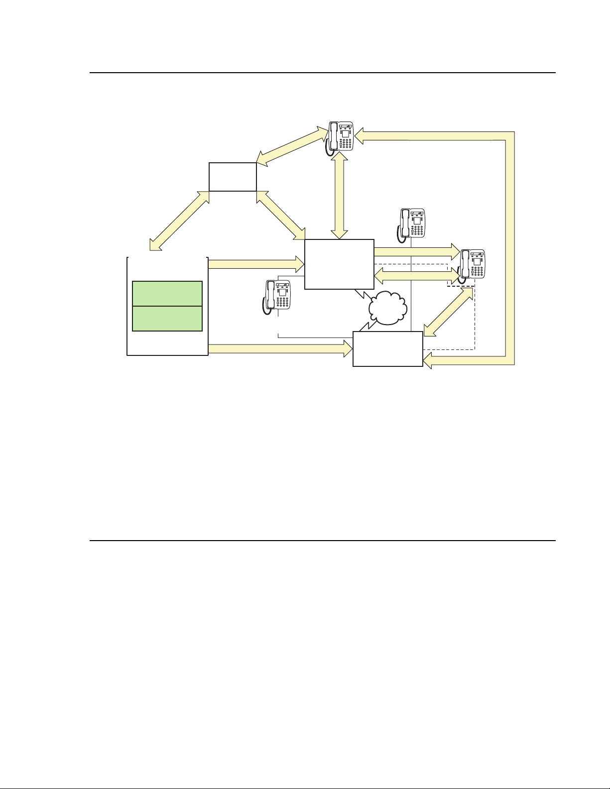
Figure 2: Communication Manager traffic flow
SIP Signaling
Avaya Media Servers
Communications
Applications
Communications
Manager
SIP Signaling
SES
SIP Signaling
CCMS Signaling over IP
Circuit-switched
Telephone
SIP
Phone
RTP Audio
Avaya Media
Gateways
G650
MCC1
SCC1
Circuit-switched
Telephone
IP
Communications
Device
H.323 Signaling
RTP Audio
RTP Audio
PSTN
RTP Audio
H.248 Signaling
Avaya G700
cynds222 LAO 012506
Figure notes:
1. SIP phones exchange RTP audio among themselves and with the G700, G650 Media
Gateways, and so forth, but not with IP phones.
2. SIP signaling from Avaya Communication Manager is always to/from SES.
3. SIP signaling can go through a C-LAN (on a G650, etc.), or directly Communication Manager
(if the server is the S8300 or S8500).
Note:
Note: This is actually true for both H.323 and H.248 signaling. The diagram gives the
impression that H.248 comes directly from Communication Manager and H.323
goes through the media gateways, when in fact both protocols can go both ways
depending on server type.
Communication Manager is the next generation of Avaya call processing software.
Communication Manager is an open, scalable, highly reliable, and secure telephony
application. Communication Manager operates on Avaya servers, and on the existing family of
DEFINITY servers.
Communication Manager carries forward all the current DEFINITY capabilities, plus all the
enhancements that enable enterprises to take advantage of new, distributed technologies,
increased scalability, and redundancy. Communication Manager is evolved from DEFINITY
software and delivers no-compromise, enterprise IP Telephony.
18 Avaya Application Solutions IP Telephony Deployment Guide
Page 19

Avaya Media Gateways support voice traffic and signaling traffic that is routed between
circuit-switched networks and packet-switched networks. The Gateways support all the
applications and adjuncts that can be used with the Avaya DEFINITY Enterprise
Communications Servers (DEFINITY ECS). These Gateways work with standards-based data
networks and easily connect with the Public Switched Telephone Network (PSTN).
Communication Manager is extensible to IP, digital and analog telephones, and wireless
business solutions. Avaya Communication Devices work with the full feature set of
Communication Manager to help enterprises be more productive by providing anytime,
anywhere access to maximize business continuity.
Avaya Communication Manager
Avaya Communication Manager provides user and system management functionality, intelligent
call routing, application integration and extensibility, and enterprise communications networking.
Communication Manager operates on Avaya servers, and on the existing family of DEFINITY
servers. For more information on the Avaya Application Solutions related features of
Communication Manager, see
Call processing on page 125.
Avaya Communication Manager
Avaya servers
An Avaya server provides centralized, enterprise-class call processing. This call processing can
be distributed across a multi-protocol network (including IP) to support a highly diversified
network architecture that consists of headquarters, branch, remote, small, and home offices.
Linux-based servers
The Avaya S8300, S8400, S8500, S8700-series, and SES-SIP are Linux-based servers. These
servers support:
● Distributed IP Networking and centralized call processing across multi-service networks
● Dual server design with hot fail-over (S8700-series Server only)
● Redundant LAN Interfaces and remote survivable call processing
For more information on the architecture and the functionality of the servers, see Hardware
Description and Reference for Avaya Communication Manager, 555-245-207.
Avaya DEFINITY Servers
Avaya Communication Manager also runs on the following DEFINITY Servers, which can be
IP-enabled:
Issue 6 January 2008 19
Page 20

Avaya Application Solutions
● Avaya DEFINITY Server R
● Avaya DEFINITY Server SI
● Avaya DEFINITY Server CSI
These servers run on the Oryx/Pecos proprietary operating system, and function in the same
way as the servers in Figure 2:
fit into Avaya CMC1, SCC1, and MCC1 Media Gateways.
The focus of this document is network design incorporating the newer Communication Manager
platforms. Therefore, the DEFINITY Servers are only discussed briefly here.
Avaya Media Gateways
An Avaya Media Gateway supports both bearer traffic and signaling traffic that is routed
between packet-switched networks and circuit-switched networks. Communication Manager
running on Avaya servers controls voice and signaling over a variety of stackable and modular
Media Gateways:
● Avaya G150 Media Gateway
● Avaya G250 Media Gateway
Communication Manager traffic flow on page 18. These servers
● Avaya G350 Media Gateway
● Avaya G450 Media Gateway
● Avaya G650 Media Gateway
● Avaya G700 Media Gateway
● Avaya G860 High Density Media Gateway
● Avaya CMC1 Media Gateway
● Avaya SCC1 Media Gateway
● Avaya MCC1 Media Gateway
● MultiTech MultiVoIP Gateway
● Avaya IG550 Integrated Gateway
The Media Gateways contain the network and the endpoint interfaces, as well as call
classification, announcement boards, and so on. Through these interfaces, Communication
Manager performs gateway/gatekeeper functions. For more information on the Media
Gateways, see
Small to mid-size enterprise on page 37 and Mid-market to large enterprise on
page 79.
Avaya Integrated Management
Avaya Integrated Management is systems-management software for managing converged
voice and data networks.
20 Avaya Application Solutions IP Telephony Deployment Guide
Page 21

The Integrated Management applications include the tools that enable you to
● configure, monitor, and optimize the performance of Avaya servers, gateways and
● endpoints
● monitor voice over IP traffic
● manage Quality of Service (QoS) policies
● control network quality
For more information on Avaya Integrated Management, see:
● Avaya Integrated Management on page 257
Avaya communication devices
Avaya Communication Manager provides intelligent control for a variety of smart
communication devices, including the one-X Deskphone family of IP telephones, IP Softphones,
digital telephones, attendant consoles, analog telephones, and wireless telephones. For
information on these devices, see Hardware Description and Reference for Avaya
Communication Manager, 555-245-207.
Avaya Communication Manager
Avaya Communication Manager applications
Avaya Communication Manager supports the following communication capabilities and
applications:
● Call Center
● Messaging
● Unified Communication Center
● Avaya Call Management System (CMS)
● Conferencing systems
● Meet-me conferencing
● Avaya Meeting Exchange Solutions
● Video Telephony Solutions
● Computer Telephony Integration (CTI)
● Application Programming Interfaces (APIs)
● Best Services Routing (BSR) polling
For more information on these applications, see Communication applications on page 152 and
ttp://www.avaya.com/support.
h
Issue 6 January 2008 21
Page 22

Avaya Application Solutions
Avaya SIP solutions
Session Initiation Protocol (SIP) is an endpoint-oriented messaging standard defined by the
Internet Engineering Task Force (IETF). SIP is a text-based protocol, similar to HTTP and
SMTP, for initiating interactive communication sessions between users. Such sessions include
voice, video, instant messaging, interactive games, and virtual reality.
As implemented by Avaya for Communication Manager release 3.0 and beyond, SIP "trunking"
functionality is available on any of the Linux-based servers (S8300, S8400, S8500 or
S8700-series). SIP trunking allows Avaya Communication Manager to communicate with SIP
endpoints and gateways across an IP network. SIP trunks allow an enterprise to connect its
server(s) to an Avaya SIP-Enablement Server (SES), a SIP-enabled proxy server, and through
this proxy to an external SIP service provider, if desired. The trunk support in Communication
Manager complies with SIP standards, specifically IETF RFC 3261, and so interoperates with
any SIP-enabled endpoint/station that also complies with the standard.
Avaya Communication Manager supports SIP endpoints, including the Avaya 4602 SIP
Telephone and Avaya IP Softphone Release 5. In addition to its IP telephony capabilities, IP
Softphone R5 also includes Instant Messaging (IM) client software, which is a SIP-enabled
application that connects to the SES for IM control. By means of having SIP-enabled endpoints
managed by Communication Manager, many features can be extended to these endpoints.
Avaya SIP application enablement
Avaya Communications Process Manager is middleware software that uses customizable web
services to integrate Avaya communications solutions into customer business processes.
Communications Process Manager achieves this integration by detecting events from a
customer business application. Different events trigger Communications Process Manager to
invoke different communication applications to escalate the situation to people and resources
that can address it.
Communications Process Manager performs the following functions:
● Integrates the following Avaya communication resources. This integration makes it
possible for the resources to communicate with Communications Process Manager and
ultimately with each other.
- Communication Manager — provides telephony capabilities.
- SIP Enablement Services (SES) — serves as the SIP proxy. All communication
resources use SIP to communicate through Communications Process Manager.
- Meeting Exchange Express — provides audio conference capabilities.
- Voice Portal — provides interactive voice response (IVR) capabilities for phone
interactions between Communications Process Manager and its users.
● Orchestrates interactions between the communication resources.
22 Avaya Application Solutions IP Telephony Deployment Guide
Page 23

Avaya Distributed Office
● Exposes composite communication service units expressed in the form of generic web
service constructs understood by the business community at large.
● Uses presence and availability computations to route communication to the right device of
the user.
Communications Process Manager makes it possible for customers to combine their data
related activities with communication to:
● Rapidly mobilize the right people for decision making (no matter where they are, or on
what device)
● Significantly reduce the human latency required today in contacting people
● Incorporate automatic alerts into business process decisions.
Communications Process Manager uses internal service-oriented architecture (SOA) with both
loose coupling between its internal components and a scriptable orchestration engine. This
architecture provides a high degree of customizability and very loose coupling between the
customer business processes and the communications systems that are used to implement the
Communications Process Manager Web services. The various components of Communications
Process Manager can be included or excluded to meet customer needs.
Avaya Distributed Office
Note:
Note: See www.avaya.com/support for a complete set of documentation for Avaya
Distributed Office.
As enterprises evaluate replacements for traditional Key-Hybrid telephone systems at the
branch, they must carefully consider investments that reduce total cost of ownership, lower
operational expenses, and enable better interaction with customers.
Distributed Office provides large and medium multi-site enterprises an elegant migration from
branch-office Key-Hybrid systems to an IP-based solution. Distributed Office is a distributed and
scalable Session Initiation Protocol (SIP) solution that delivers local telephony and
communications applications to multiple locations. Target markets include financial services
outlets, retail stores, transportation depots, and regional offices for government and other
industries. Replace variable w/ short product name supports centralized administration and can
be rapidly deployed as either individual branch locations or as a network of branch locations.
Distributed Office is based on open standards using SIP and Web-Services for maximum
investment protection.
This highly available solution does not depend on WAN health for local branch operation
because call processing is distributed to each branch location. Yet customers can still link
branches together, routing voice, presence, and instant messaging, and also leverage
connections to corporate headquarters to provide enhanced customer service.
Issue 6 January 2008 23
Page 24

Avaya Application Solutions
Avaya Distributed Office contains integrated features, applications, and much more. At each
branch location, Distributed Office is implemented in one of two platforms — Avaya Distributed
Office i40 or Avaya Distributed Office i120. These platforms are available in numerous
configurations.
Distributed Office Configurations
An Avaya Distributed Office system can be configured as
● an individual branch location
● an individual branch location with centralized management
● a Networked branch location
The diagram in Figure 3
shows a Distributed Office solution with networked branch locations.
This configuration supports:
● SIP calls between the branch and main locations over the private WAN or public Internet.
● Inter-branch SIP calls through an SIP Enablement Services (SES) edge proxy at the main
location.
● Integrated Management for Distributed Office at the main location provides centralized
management to the branch locations.
● Optional connection to Communication Manager server through the SES home proxy.
24 Avaya Application Solutions IP Telephony Deployment Guide
Page 25
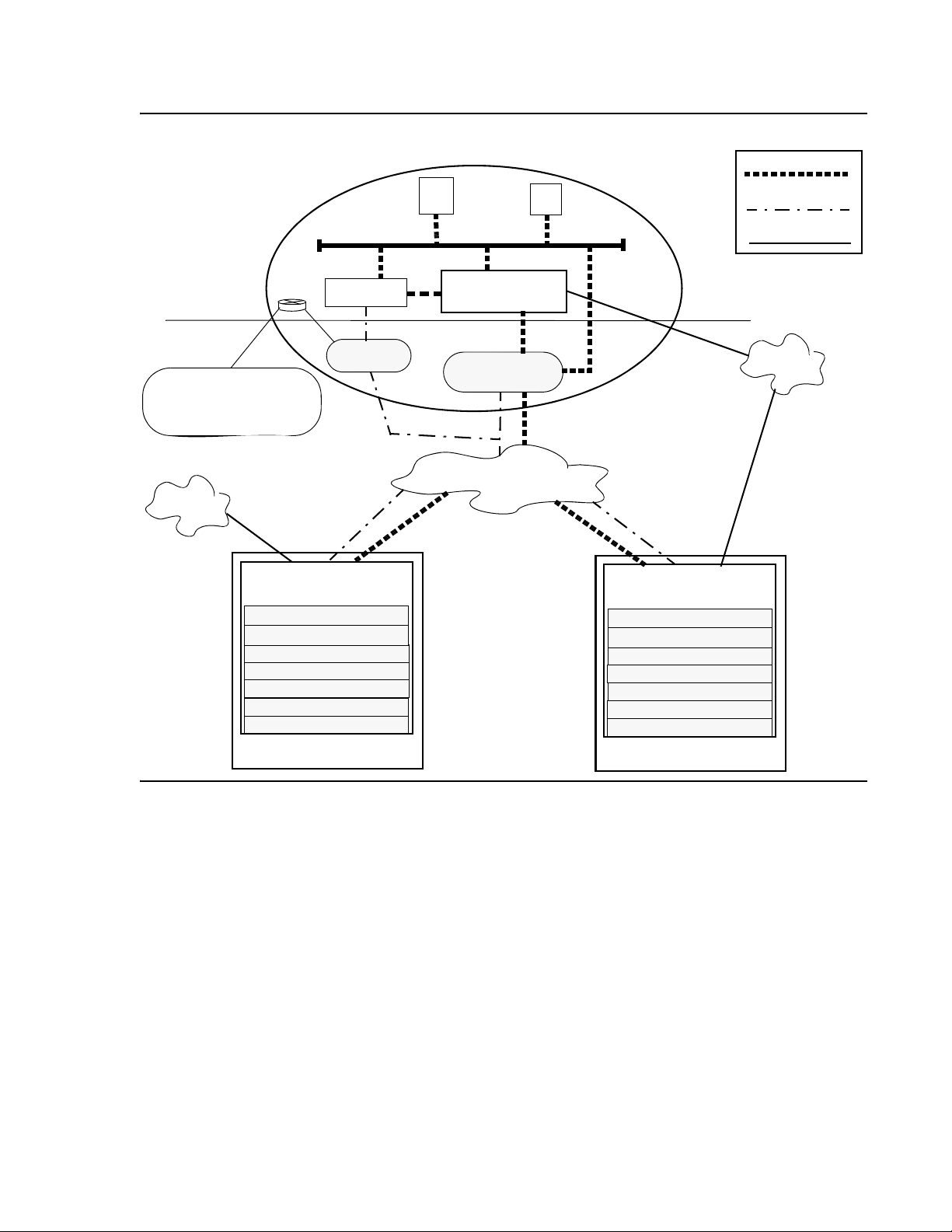
Figure 3: Networked remote sites
Avaya Distributed Office
Optional
components
Traps sent to the Avaya
Secure Enhanced Alarming
receiver via customer VPN
(requires SAC-Lite)
PSTN
Distributed Office
Feature Server
SIP Enablement Services
Local Manager
CTI and TAPI applications
Automated Attendant
Voice mail
Secure Enhanced Alarming
SIP, H.323, and analog
telephones, fax
SES home
i40
Main business location
SIP
Apps
Communication
servers
Central
Manager
Manager
SES edge
private WAN
Branch locations
SIP
IVR
SIP
SIP
Management
TDM
T
Distributed Office
i120
Feature Server
SIP Enablement Services
Local Manager
CTI and TAPI applications
Automated Attendant
Voice mail
Secure Enhanced Alarming
SIP, H.323, and analog
telephones, fax
PSTN
Issue 6 January 2008 25
Page 26

Avaya Application Solutions
Distributed Office benefits
The benefits of Avaya Distributed Office include advanced functionality such as:
● Platform features
- Feature server including both PBX and Key-System features
- SIP Enablement Services
-Voice Mail
- Announcements
- Auto attendant
- Call Detail Recording
- Secure Enhanced Alarming
● Application Enablement Services
- Extend Avaya’s rich features in an IP environment to get the most from your current investment.
- Integrate communications & business applications to leverage existing infrastructure and
maximize efficiency.
- Support some third-party application integration to provide mission-critical support for key
business processes.
- Computer-telephony integration services.
Distributed Office implementation
The Distributed Office solution provides a set of standard hardware configurations or constructs
and set of provisioning profiles. A construct is chosen that best satisfies the hardware
requirements for one ore more locations. A provisioning profile, consisting of a set of files
containing provisioning data, is selected and loaded onto the hardware platform.
Selecting a construct
When you use the Avaya Solution Designer to create a configuration template for a group of
branch locations, the choice of a construct is the most important parameter. The choice of
construct determines the number of lines and trunks of each type. The goal is to choose the
smallest construct that accommodates the maximum requirements assuming growth.
The first consideration when choosing a construct is the Distributed Office model, i40 or i120. A
construct that uses the i120 model provides a larger number of lines and trunks than the i40, as
well as higher capacities for several other parameters such as the number of voice mail boxes,
the number of DSPs, and the busy hour call completion rate.
26 Avaya Application Solutions IP Telephony Deployment Guide
Page 27

Avaya Distributed Office
An i40 might provide an adequate number of lines and trunks for the current business
requirements but not for increased requirements in two years based on growth assumptions. Or,
an i40 might provide enough lines and trunks for the next several years but another parameter,
such as the number of DSPs to handle large Fax volumes might not be sufficient. In either case,
one of the i120 constructs would be a better choice.
Table 1:
i40 constructs on page 27 and Table 2: i120 constructs on page 29 provide the
information needed to choose a construct.
Note:
Note: The list of available constructs might change over time. Check on the Avaya
Distributed Office web site for the latest set of available constructs.
i40 constructs
Each i40 construct contains the following ports:
● One console cable port
● One interface USB port (located on the chassis where you connect the Disk on Key)
● One Contact Closure Adjunct (CCA) port
● One Ethernet WAN port (not used with Distributed Office)
● Eight Ethernet LAN Power over Ethernet (PoE) ports
● One USB port (for use with a USB modem for servicing the platform)
● One Ethernet services port
● Two analog line ports
In addition to these ports, the i40 contains additional ports based on its construct. Table 1
the three i40 constructs, and a description of what additional ports are available for each.
shows
Table 1: i40 constructs
Construct
Analog
trunk
ports
ISDN BRI
trunk
ports
i40 - Analog 4
i40 - BRI 1 2
i40 - DS
2
1. The T1/E1 interface port can be configured for ISDN PRI,
Robbed Bit, or CAS signaling.
1
2. The i40 - DS1 construct also contains three pairs
of test jacks that are used by service personnel
only.
T1/E1
interface
1
port
1
Issue 6 January 2008 27
Page 28

Avaya Application Solutions
i120 constructs
Each i120 construct contains the following ports:
● One analog trunk port
● Two analog line ports
● One Contact Closure Adjunct (CCA) port
● One Ethernet WAN port (not used with Distributed Office)
● One Ethernet LAN PoE port
● One console cable port
● One interface USB port (located on the chassis where you connect the Disk on Key)
● One USB port (for use with a USB modem for servicing the platform)
● One Ethernet services port
Note:
Note: If you need additional ports, additional Media Modules are available for the i120
platform constructs. See your Avaya representative for details.
In addition to these ports, the i120 contains additional ports based on its construct. Table 2
shows the ten i120 constructs, and a description of what additional ports are available for each.
The legend for the various construct names is a follows:
Legend:
A = Analog (RJ-11, 2-wire)
B = BRI
D = Digital (DS1, T1, E1, and PRI)
H = High Capacity (24 analog ports using a single connector)
P = Power over Ethernet (PoE)
28 Avaya Application Solutions IP Telephony Deployment Guide
Page 29

Table 2: i120 constructs
Avaya Distributed Office
Construct
Analog
ports for
lines or
trunks
Analog
line ports
10/100
Ethernet
Base-T
PoE ports
T1/E1
interface
1
port
ISDN BRI
trunk
ports
i120 - A 8
i120 - AH 8 24
i120 - A2H 8 48
i120 - AP 8 40
i120 - 2AP 16 40
i120 - D2H2
8 48 1
i120 - DP2 8 40 1
i120 - BH 8 24 8
i120 - B2H 8 48
i120 - BP 8
1. The T1/E1 interface port can be configured for ISDN PRI, Robbed Bit, or CAS signaling.
40 8
2. The i120 - DH and i120 - DP constructs also contains three pairs of test
jacks and a connector that are used by service personnel only.
8
Distributed Office application module and media modules
Avaya AM110 Application Module
The Avaya AM110 Application Module is the heart of the Replace variable w/ short product
name system. The AM110 Application Module provides the telephony features, voice mail,
automated attendant, SES, and TAPI. The AM110 Application Module also contains a Freescale
processor and replaceable Compact Flash and SO-DIMM memory.
The AM110 Application Module is included with both the i40 and i120 platforms. The Avaya
AM110 Application Module can be inserted only in slot V1 of either the i40 or the i120.
Issue 6 January 2008 29
Page 30

Avaya Application Solutions
Telephony media modules
The ten constructs for Distributed Office i120 contain one or more media modules. Tab le 3
shows the available media modules, and the slot or slots in which each module can be inserted.
Table 3: Supported media modules
Module Description Permitted slots
MM710 One T1/E1 ISDN PRI trunk port V2, V3, V4, V5
MM711 Eight universal analog ports V2, V3, V4, V5
MM716 Twenty-four analog line ports V2, V3, V4, V5
MM720 Eight ISDN BRI trunk ports V2, V3, V4, V5
Telephony modules
LAN module
MM316 Forty 10/100 Ethernet ports with Power over Ethernet (PoE),
and one 10/100/1000 Ethernet copper uplink/access port
Streamlined Deployment
A major goal of the Distributed Office offering is to minimize the time to deploy the Distributed
Office systems at the branch locations. The total deployment time includes:
● Unpacking, assembling, and cabling the hardware
● Enter site-specific and other dynamic data
● Acceptance testing
The first and third deployment items require a fixed amount of time for each construct. The time
required for the second item, completing the provisioning data, varies according to the amount
of data that needs to be added or changed in the profile that was loaded onto the system or onto
a USB portable storage device, or "Disk on Key" (DoK).
The design activities described previously determine the type and the number of the Distributed
Office hardware components for each branch location. The implementation process then uses
data files called profiles to load the translations and other parameter values onto the i40 or i120
Distributed Office platform before it is shipped to the customer site.
V6
In the design phase, the Sales Engineer uses the Avaya Solution Designer to create a purchase
order that specifies the Distributed Office hardware for each branch location. For each branch
location or group, the Sales Engineer specifies that the provisioning profile is:
● Standard — The profile is one of a set of profiles that have been previously defined and
associated with a hardware construct.
30 Avaya Application Solutions IP Telephony Deployment Guide
Page 31

● Custom — The profile is not a Standard profile and needs to be created.
● None (Default)— The default profile associated with the hardware construct will be
shipped and the provisioning data will be entered when the system is installed.
The deployment of a Distributed Office system is called "configure-to-order" if the provisioning
profile is standard or custom. The deployment is called "made-to-stock" if the default profile is
shipped. For a configure-to-order deployment, some or all of the customer-specific provisioning
data is loaded onto the Distributed Office platform and all of the system components are
assembled and tested before it is shipped to the customer site. A configure-to-order deployment
minimizes or eliminates the implementation tasks at installation time.
For a made-to-stock deployment, no customer-specific provisioning data is associated with the
Distributed Office system before it is shipped to the customer site. The system components are
shipped separately from one or more distribution points. The made-to-stock platform contains a
default profile that provides a minimal amount of provisioning data that is needed for the
hardware construct.
Provisioning status
The provisioning status of a Distributed Office system when it is shipped to the customer
location is one of the following:
Avaya Distributed Office
Fully configured. Minimum additions or changes to the provisioning data. Use Local Manager
to check the data.
Partially configured. Some additions or changes to the provisioning data. Use the
Profile-based Setup Assistant to add or change the dynamic portion of the provisioning data.
Configure from scratch. All provisioning data must be entered. Use the Initial Setup Assistant
to make the system operable. Then use Local Manager to enter the provisioning data.
Fully configured systems
For a fully configured system, all of the provisioning data, including location-specific data, has
been obtained from the customer and loaded onto the i40 or i120 Distributed Office module
before shipment to the branch location. At installation, only the hardware assembly and
acceptance testing is required.
Typically, there will be some minor additions or adjustments to the provisioning data. This can
be done either locally, using the Local Manager application, or remotely, using the Distributed
Office Central Manager.
Issue 6 January 2008 31
Page 32

Avaya Application Solutions
Partially configured systems
For a partially configured system, a Standard profile is selected or a Custom profile is created
that contains some of the provisioning data. The profile contains a section for dynamic data,
which is either missing and needs to be added or is temporary and needs to be confirmed or
changed. The partially configured profile is either loaded onto the i40 or i120 Distributed Office
module or copied to a USB portable storage device before shipment to the branch location.
A Profile-based Setup Assistant is created as part of the profile. At installation, the Assistant
prompts the installer to add or change the dynamic data.
From-scratch configuration
If none of the profiles, including the default profile, is appropriate, the system can be reset to its
initial configuration by executing the nvram init command. In this case the Initial Setup
Assistant is used to enter the minimum provisioning data to make the system operable. Then
the remaining provisioning data is entered using Local Manager.
32 Avaya Application Solutions IP Telephony Deployment Guide
Page 33

Avaya Application Solutions platforms
Overview
The Avaya Communication Manager portfolio covers small, medium, and large enterprises with
advanced communications needs between 2 and 48,000 ports per system. This chapter
provides an overview of the Avaya Communication Manager platforms architecture that
supports Avaya Application Solutions components and features.
Figure 4
Figure 4: Avaya Application Solutions platforms port capacities
An overview of the properties of the Avaya servers described in this chapter is provided in
Table 4:
capacities on page 34.
shows the approximate port capacities for Avaya’s Application Solutions platforms.
450 32002
S8300
S8400
S8500
IP Connect
S8700 Series
cynd103f LAO 013006
Avaya Application Solutions comparison matrix — components, performance, and
44K1300
Issue 6 January 2008 33
Page 34

Avaya Application Solutions platforms
Table 4: Avaya Application Solutions comparison matrix — components, performance,
and capacities
Processor/
RAM/
disk drive
1
Avaya S8300 Server Avaya S8400
Intel Celeron class
Server
Intel Celeron M
server
512 MB of RAM
30 GB hard disk drive
512 MB RAM
30 GB hard disk
drive
2 GB Solid State
Disk (SSD)
Avaya S8500 Server Avaya S8700-series
Intel Pentium IV
Class Server
512 MB of RAM
80 GB hard disk
Server
S8710:
Intel Pentium IV Class Server
512 MB RAM
72 GB disk drive
drive
Removable Flash card backup
Removable Flash
card backup
S8720:
AMD Opteron
1 GB RAM
72 GB disk drive
Removable Flash card backup
S8730:
AMD Dual Core Opteron
4 GB RAM
72 GB disk drive
General
Business
analog
equivalent
BHCC rate
Maximum
Telephones
(IP + non-IP)
Maximum
Trunk s
(IP + non-IP)
10,000 10,000 100,000 fiber-PNC:
400,000
180,000 IP station to trunk calls
80,000 H.248 media gateway
calls
25,000 SIP calls
IP-PNC:
180,000
S8300: 450
900 2,400 36,000
S8300/G700: 450
S8300/G450: 450
S8300/G350: 40
S8300/G250: 12
S8300: 450
S8300/G700: 450
400 800 8,000 Total
up to 5,000 can be SIP
S8300/G450: 450
S8300/G3502: 40
S8300/G250: 10
For XL configuration:
12,000 Total
1 of 2
34 Avaya Application Solutions IP Telephony Deployment Guide
Page 35

Overview
Table 4: Avaya Application Solutions comparison matrix — components, performance,
and capacities
Maximum
IP Endpoints
(IP Telephones
+ IP Trunks)
Maximum
Subtending
Media
Gateways
1
(continued)
Avaya S8300 Server Avaya S8400
Server
S8300: 900 Total
S8300/G700: 900 Total
1,300 Total
400 Trunks
450 Trunks
450 Telephones
900 Telephones
(450 can be SIP)
S8300/G450: 900 Total
450 Trunks
450 Telephones
S8300/G350: 55 Total
15 Trunks
40 Telephones
S8300/G250: 20 Total
10 Trunks
10 Telephones
S8300/G700/G450:
50 H.248
5 H.248
A single PN
S8300/G350/G250:
subtending gateways
not supported
composed of:
1–5 G650s
1–3 G600s
1–4 CMC1s
Avaya S8500 Server Avaya S8700-series
Server
3,200 Total
12,000 Total (all can be SIP)
For XL configuration:
800 Trunks
16,000 Total (12,000 can be
SIP)
2,400 Telephones
(all can be SIP)
8,000 Trunks
For XL: 12,000 Trunks
250 H.248
3 MCC1 or SCC1
PNs Direct connect
250 H.248
fiber-PNC:
44
MCC1 or SCC1 PNs with CSS
64
MCC1 or SCC1 PNs with ATM
64 G650 PNs
(IP-PNC)
Maximum
Media
Gateways per
LSP
Reliability /
survivability
50
per S8300 LSP
LSP
3
SLS
5
per S8300 LSP
LSP for
G700/G450/
G350/G250
250
per S8500 LSP
50
per S8300 LSP
LSP backup for
G700, G450, G350,
or G250
S8500 ESS
Sockets on
Processor
Ethernet
interface
1,700 1,700 2,500 NA
1. The operating system for all servers is Linux (Red Hat Enterprise Linux 4.0).
IP-PNC:
64
G650 PNs
250
per S8500 LSP
50
per S8300 LSP
Duplicated Processor
LSP backup for G700, G450,
G350, or G250
S8700-series ESS
S8500 ESS
Duplicated control network
Duplicated bearer connectivity
2 of 2
Issue 6 January 2008 35
Page 36

Avaya Application Solutions platforms
2. S8300/G350 trunks either H.323 or SIP. Up to 15 IP trunks
3. Each G250 has built-in Standard Local Survivability (SLS) that provides basic services for local IP and
non-IP phones and PSTN trunks. The G150 also has built-in survivability with features similar to those of
the IP Office communication product, on which the G150 is based.
4. H.248 Media Gateways include G250, G350, IG550, G700 and G450.
Terminology
The terms IP-PNC and fiber-PNC are used in this chapter to distinguish between the two types
of port network connectivity (PNC). Synonyms are IP-connected and Fiber-connected,
respectively.
Fiber-connected port networks (fiber-PNC) transport bearer traffic (voice, fax, video) between
PNs over fiber-optic cables using circuit-switched (TDM) protocol. IP-connected port networks
(IP-PNC) transport bearer traffic over Ethernet cables using packet-switched Internet Protocol
(IP). Starting with Communication Manager release 3.0, both types of port network connectivity
can be combined in the same system. This allows a system to be converted from fiber-PNC to
IP-PNC gradually, one port network at a time, if desired.
Note:
Note: The term fiber-PNC is used in this document with almost the same meaning as
the term multi-connect, which, in addition to fiber-connected PNs to carry the
bearer traffic, implies a dedicated control network. The term fiber-PNC applies to
configurations with either a dedicated on non-dedicated control network.
There are three kinds of fiber-PNC configurations:
Direct connect - One port network (PN), the "control PN," is IPSI-connected to the control
network and one or two additional PNs are fiber-connected to the control PN. The call
controller can be an S8500 Server or an S8700-series Server pair. The fiber connections
are between the expansion interface (EI) circuit packs (TN570) in the PNs.
Center Stage Switch - All PNs are fiber-connected through the center-stage switch (CSS) and
one or more PNs are connected to the control network through an IPSI circuit pack
(TN2312). The call controller is an S8700-series Server pair. The fiber connections are
between the switch node interface (SNI) circuit packs (TN573) in the switch node carrier
and the expansion interface (EI) circuit packs (TN570) in the PNs, or between SNIs in two
switch-node carriers.
ATM - All PNs are fiber-connected through the Asynchronous Transfer Mode switch and one or
more PNs are-connected to the control network through an IPSI. The call controller is an
S8700-series Server pair. The fiber connections are between the ATM switch and the ATM
expansion interface (ATM-EI) circuit packs (TN2305B or TN2306B) in the PNs.
36 Avaya Application Solutions IP Telephony Deployment Guide
Page 37

Small to mid-size enterprise
Avaya S8300 Server and Avaya G700, G450, G350, or G250 Media Gateway
The S8300 Server and G700 Media Gateway solution (Figure 5: Avaya G700 Media Gateway
with the S8300 Server on page 37) seamlessly delivers voice, fax, and messaging capabilities
over an IP network. This unique solution converges the power of the Avaya Communication
Manager feature set with the power of distributed Ethernet switching from the P330 Stackable
Switching System.
Figure 5: Avaya G700 Media Gateway with the S8300 Server
Small to mid-size enterprise
ALM PWR
V1
ALM
TST
ACT
OKTO
REMOVE
msdcs83b KLC 031402
LNK COL Tx Rx FDX FC Hspd LAG EXT1
CPUMSTR
SHUTDOWN
51 52 53 54 55 56 57 58
59 60 61 62 63 64 65 66
SERVICES USB 1 USB 2
EXT2
V2
V3
V4
EXT 1 EXT 2 CONSOLE
EISO EMSM EOSI
ALM
TST
ACT
SIG
E1/T1 EIA 530A DCE
ALM
TST
ACT
123456 87
ALM
TST
ACT
123456 87
The G250, G350, G700, or G450 with an S8300 as the primary controller is a stand-alone
solution. The Linux-based S8300 Server can support up to 50 G250, G350, G700, or G450
Media Gateways. For more information about performance and capacities of the S8300 Server,
see Tab le 4 :
Avaya Application Solutions comparison matrix — components, performance, and
capacities on page 34.
An S8300 Server and G250, G350, G700, or G450 Media Gateway solution includes:
● A G700, G450, G350, or G250 Media Gateway is always required. The G700, G450,
G350, or G250 hosts an S8300 Server and various media modules depending on the
telephony needs at a particular location.
● The S8300 Server. The S8300 Server is inserted into a media module slot. If present, the
S8300 supports Communication Manager that provides call-processing capabilities and
features for the system. The S8300 can be configured as the primary call controller or as a
Local Survivable Processor (LSP) standby server for another S8300 Server in the
configuration.
Note:
Note: The S8300 / G350 solution is intended to be a standalone solution. Multiple
media gateways (either G700, G450, G350, or G250) should be controlled by an
S8300 Server installed in a G700 or G450 Media Gateway.
Issue 6 January 2008 37
Page 38

Avaya Application Solutions platforms
ALM
TST
ACT
1 2 3 4 5 6 87
ALM
TST
ACT
1 2 3 4 5 6 87
REMOVE
ALM
TST
ACT
OKTO
SHUTDOWN
SERVICES
USB1
USB2
E1/T1
EIA 530A DCE
ALM
TST
ACT
SIG
EISO EMSM EOSI
ALM
TST
ACT
1 2 3 4 5 6 87
ALM
TST
ACT
1 2 3 4 5 6 87
REMOVE
ALM
TST
ACT
OKTO
SHUTDOWN
SERVICES
USB1
USB2
E1/T1 EIA 530A DCE
ALM
TST
ACT
SIG
EISO EMSM EOSI
ALM
TST
ACT
1 2 3 4 5 6 87
ALM
TST
ACT
1 2 3 4 5 6 87
REMOVE
ALM
TST
ACT
OKTO
SHUTDOWN
SERVICES
USB1
USB2
E1/T1
EIA 530A DCE
ALM
TST
ACT
SIG
EISO EMSM EOSI
Multiple G700 Media Gateways can be connected to each other through an Octaplane 8-Gbps
stacking fabric, and Avaya P330 Expansion Modules, which allows adding additional Ethernet
ports, fiber interfaces, ATM access or WAN access modules without additional switches. The
system can be networked to other PBXs and Communication Manager platforms through an IP
network.
Some of the key characteristics of this platform are
● Expert System Diagnostic Capability
● Hot-swappable Media Modules
● Co-resident INTUITY AUDIX messaging.
The platform is scalable, and has survivability and redundancy capability through a Local
Survivable Processor (LSP), which supports all of the features of Communication Manager.
Figure 6: Avaya S8300/G700, G450, G350, or G250 in a stand-alone configuration
Stand alone Office
PSTN
with IP Trunk link
to Avaya PBXs
ALM
TST
ACT
SIG
E1/T1
EIA 530A DCE
ALM
ALM
TST
TST
ACT
ACT
OKTO
USB1
USB2
ALM
TST
ACT
G700/G350
with S8300/ICC
ALM
TST
ACT
OKTO
REMOVE
IP
G700/G350
SHUTDOWN
SERVICES
USB1
USB2
PC
Phone
G700 hardware architecture
The design of the Media Gateway motherboard hardware brings together a multitude of
hardware functions into a single 2U 19-inch rack-mountable enclosure. Integrated on the
motherboard are:
ISDN-PRIISDN-PRI
ALM
TST
ACT
OKTO
ALM
TST
ACT
SIG
EIA 530A DCE
ALM
TST
ACT
ALM
TST
ACT
DCPFax
ALM
TST
ACT
SIG
ALM
TST
ACT
USB1
USB2
ALM
TST
ACT
G700/G350
Edge
Router
IP WAN
IP TIE Trunk
Avaya IP PBX
( S8300, S8700)
Ethernet (LAN)Ethernet
Edge
Router
cynds110 LAO 101104
IP
Phone
● A gateway function that bridges the IP and telephony domains
● An Ethernet switching function and associated management features through an
integrated Layer 2 switch architecture
● Processing elements that are necessary to support traditional telephony interfaces, such
as trunks and analog/DCP lines
38 Avaya Application Solutions IP Telephony Deployment Guide
Page 39

Small to mid-size enterprise
These processing elements are controlled by Communication Manager, thus offering the
complete set of Communication Manager call features to both IP users and traditional telephony
users.
From a hardware perspective, the G700 Media Gateway is an enclosure with an internal power
supply and a motherboard. This design that provides the hardware resources for the Gateway
functions, and electrical connectivity for four media modules, one Cascade module, and one
Expansion module. The enclosure houses the power supply and the motherboard, and provides
the physical support to allow the insertion of the various modules. Figure 7:
Avaya G700 Media
Gateway (front view) on page 39 shows the Media Gateway enclosure.
Figure 7: Avaya G700 Media Gateway (front view)
4
EISO EMSM EOSI
ALM
TST
1
ALM
TST
ACT
SHUTDOWN
OKTO
2
REMOVE
3
SERVICES USB 1 USB2
5
6
ACT
SIG
E1/T1 EIA 530A DCE
ALM
TST
ACT
123456 87
ALM
TST
ACT
123456 87
7
7
7
8
cynds111 KLC 121003
Figure notes:
1. LED board
2. S8300 Server
3. Services port
4. USB ports
5. Avaya P330 Expansion Module
6. 10/100 Base T Ethernet ports
7. Media Modules
8. Serial (“Console”) connector
The four media module slots can be populated with any combination of media module types,
including:
● T1/E1 with integrated CSU/DSU (MM710)
● 8-port analog line/trunk (MM711)
● 8-port DCP line (MM712)
● 24-port analog line (MM716)
● 8-port BRI trunk (MM720)
● VoIP Engine (MM760)
● Internal Communications Controller (ICC-only 1 per gateway; must be in the first slot)
The Cascade module comes from the Converged Infrastructure LAN Switches product line, and
provides the Octaplane interface:
● One full-duplex 4-Gbps Ethernet port (8 Gbps bandwidth) for high-speed interconnection
of up to 10 media gateways and P330 data switches in a stack arrangement
● Expansion module interface allows the use of expansion modules in the gateway. These
expansion modules also allow WAN access routing.
Issue 6 January 2008 39
Page 40

Avaya Application Solutions platforms
The G700 motherboard hardware design involves three major blocks:
● A DSP engine and associated packet processor complex. This complex performs IP/UDP/
RTP processing, echo cancellation, G.711 A/µ, G.729 (with or without silence
suppression), fax relay, silence suppression, jitter buffer management, packet loss
concealment, and so on.
● A Gateway Processor complex. This complex is the master controller of the Gateway, and
controls all resources inside the Gateway under the direction of the Gateway Controller.
Examples of the functions implemented here include the Media Module Manager, Tone/
Clock, PKTINT, Announcements (record/playback), and H.248 signaling to the Gateway
Controller.
● An Intel 960 processor complex. This complex is based on the architecture of the P330
data switch. This complex provides an eight-port Layer 2 switch function, and the i960
manages the Expansion and Cascade modules.
These major blocks are interconnected through two major communication paths: an Ethernet
link and the Time Division Multiplexed (TDM) bus similar to that in a port network. In addition,
the motherboard provides electrical and physical connectivity for four media modules.
VoIP Engine complex
The internal VoIP Engine block is where PCM voice samples are encoded and put into IP
packets, and vice-versa. This block implements all the functions that are normally associated
with a Gateway. Such functions include packet loss concealment, jitter buffer management,
transcoding, and so on.
The VoIP Engine of the G700 motherboard has three major components: two Digital Signal
Processors (DSPs), and a Motorola MPC8260 processor. The DSPs together provide the same
VoIP channel capacities as the TN2302AP IP Media Processor circuit pack: 64 G.711 channels
or 32 G.729 channels.
Each additional VoIP Media Module (MM760) increases the VoIP channel capacity of a G700
media gateway by the equivalent of a TN2302AP circuit pack.
The G700 Media Gateway Processor
The G700 Media Gateway Processor (MGP) is the master controller of the Media Gateway. The
Motorola 860T processor in this complex implements the H.248 protocol to communicate with
the Gateway Controller. Under the direction of the Gateway Controller, the 860T Gateway
Processor controls the flow of data through the Gateway. The 860T processor communicates
with other processors in the system – the VoIP Engine processor, the i960 processor, and any
processors on media modules – through either the control channel of the TDM bus, or an
Ethernet link (the i960 processor connects only through Ethernet).
Functions implemented within the MGP complex include:
● Management of the media modules (reset control, board and interface insertion, and so on)
● Termination of the LAPD protocol running on the D-channel of E1/T1 trunks and BRI lines
and trunks (32 channels capacity).
40 Avaya Application Solutions IP Telephony Deployment Guide
Page 41

Small to mid-size enterprise
● Recorded announcement playback (15 playback channels, 1 record channel)
● Tone detection and generation (15 ports of tone detection)
● System clock generation and synchronization to an external network timing reference
● Download agent for the media modules
● License/translation storage
● System maintenance
● H.248 signaling
● Connection management
Avaya IA770 INTUITY AUDIX Messaging Option for S8300/G700
The Avaya IA770 INTUITY AUDIX Messaging Application, (IA770), optionally embedded on the
S8300 Server installed in a G700, delivers voice, fax, and e-mail to enhance and simplify the
communications and the exchange of information within both small enterprises, and the smaller
locations of large enterprises. The IA770 uses the Linux operating system, which is consistent
with the operating system of the Media Gateway.
The IA770 supports INTUITY digital (TCP/IP) and AMIS networking protocols. More extensive
networking can be provided with the Avaya Interchange.
The IA770 consists of license-file-activated software that resides on the S8300 Server, and an
ICC daughter card, which is field-installable and upgradeable. For Communication Manager 2.2
and later, new installations will implement IA770 Embedded Messaging H.323 integration on the
S8300, and will no longer use the ICC daughter card.
Voice Announcement over the LAN
Voice Announcement over the LAN (VAL) capabilities are co-resident on the Avaya G700 Media
Gateway. This G700 VAL announcement capability allows backup and restore of
announcements to an external PC or a file server on the customer’s local area network (LAN),
in addition to internal backup in Flash memory. The announcements are stored as
industry-standard waveform (.wav) files. This enables customers to create high-quality, studio
announcements, save the announcements to their PC or server, and then share the same
announcements with multiple Avaya Application Solutions. Other features of the G700 VAL
announcement offer include:
● A G700 VAL announcement source functions the same as the TN2501AP for
administration, recording, file handling using FTP, playback, and measurements.
● Each G700 VAL announcement source used is counted as a VAL board towards the
Maximum VAL boards on the customer-options screen. The S8300 Server now comes
with a license entitlement for using up to 50 VAL circuit packs. The S8700-series Server
comes with a license entitlement for one, and requires the purchase of additional licenses
to enable the maximum of 50 which applies to both TN2501AP and G700 VAL sources.
Issue 6 January 2008 41
Page 42

Avaya Application Solutions platforms
● Voice quality is impacted when played over IP. However, quality is acceptable even with 2
hops and 10-msec delay.
● The use of G700 VAL sourced announcements impacts that gateway’s overall occupancy,
and IP Telephony resources (for example, high use global announcements such as the
main greeting and some VOAs) should be handled by TN2501 circuit packs if the agents
are not homed to that G700.
● FTP access for the G700 announcements use the same IP address as the address that is
assigned to the G700 when installed (this address is displayed on the Media-Gateway
form).
S8300 primary controller architecture
The S8300 Server has the same form factor as the Avaya media modules. The S8300 is
installed in slot V1 of the G700, G450, G350, or G250 Media Gateway. The S8300 can be
configured as either a primary controller (a.k.a. “ICC”) or as a local survivable processor (LSP).
Configured as a primary controller, the S8300 provides Communication Manager call control.
The controller targets the small-line-size, cost-conscious portion of the market, and as such,
must be cost competitive with other solutions. The controller is based on standard Intel IA32
architecture, and runs the industry-standard Linux operating system.
The S8300 runs the following co-resident applications:
● H.248 Media Gateway Controller
● H.323 GateKeeper
● Communication Manager Feature Server
● INTUITY AUDIX Messaging system (installed in the G700)
The S8300 primary controller, when installed in the G700, can be ordered both with and without
INTUITY AUDIX support.
The S8300 faceplate provides connectivity for two USB devices, and an Ethernet port for
technician access. The faceplate also has operational LEDs and a shutdown switch. The media
module backplane connector provides the interfaces for the internal 10/100 Ethernet bus and
the TDM Bus.
For information on S8300 performance and capacities, see Tab le 4 :
Avaya Application
Solutions comparison matrix — components, performance, and capacities on page 34.
42 Avaya Application Solutions IP Telephony Deployment Guide
Page 43

S8300 as an LSP
The S8300 Server installed in a G700, G450, G350, or G250 Media Gateway can be configured
as a Local Survivable Processor (LSP). The LSP provides survivability when the primary
controller, either an S8300 ICC or an S8700-series External Communications Controller (ECC),
is inaccessible. Each system can have multiple LSPs. Each LSP has a copy of the primary
controller’s translations. The translations are updated regularly from the primary controller by
way of a virtual link through an IP network. Typically, all LSPs are in idle mode, where the LSPs
are not processing any calls. When the Media Gateway's Processor (MGP) or individual IP
endpoints perceive the primary controller to be unreachable, the MGP or the IP endpoints
attempt to register with an LSP. The LSP does not actively take over when the primary controller
becomes unreachable, but waits for MGPs and IP endpoints to register with it. Each LSP runs in
license-normal mode until IP Telephones or MGPs register with it, which triggers the LSP to
move into a license-error mode. Each LSP can run in active mode for a maximum of 10 days
per outage before it must be reset manually.
Based on administration of Communication Manager, the G700/G450/G350/G250 LSP can
return control of the G700/G450/G350/G250 Media Gateway to the primary controller (server)
automatically when the connection is restored between the media gateway and the primary
controller. By returning control of the media gateways to the primary controller automatically,
Communication Manager software easily and quickly eliminates the fragmentation between
remote gateways in the network created by LAN/WAN communication failures with the primary
controller. The fall-back from the LSP to the primary controller may also be manual using a reset
on the LSP. This reset breaks the communication between the LSP and each registered
endpoint. This break causes the endpoints to register with the primary controller. However, most
active calls are preserved.
Small to mid-size enterprise
Note:
Note: The S8500 can also be configured as an LSP.
G450 Media Gateway
For additional information on the G450, see Overview for the Avaya G450 Media Gateway,
03-602058.
The Avaya G450 Media Gateway is a multipurpose media gateway that can be deployed in
medium- to large-sized branch locations or in wiring closets servicing buildings and floors, in a
campus environment. It works in conjunction with Avaya Communication Manager IP telephony
software running on Avaya S8xxx Servers to deliver intelligent communications to enterprises of
all sizes.
The G450 combines telephone exchange and data networking, by providing PSTN toll bypass
and routing data and VoIP traffic over the WAN. The G450 features a VoIP engine, an optional
WAN router, and Ethernet LAN connectivity. The G450 provides full support for Avaya IP and
digital telephones, as well as analog devices such as modems, fax machines, and telephones.
Issue 6 January 2008 43
Page 44

Avaya Application Solutions platforms
The G450 can support up to 450 users when deployed as a branch gateway in a mid to large
branch office of a large enterprise or a call center, and can serve up to 2400 users when
deployed as a campus gateway. Both configurations require Avaya Communication Manager IP
telephony software running on one or more Avaya S8xxx Servers. The 450 user capacity is
reached when the Avaya S8300 server is used and the 2400 user capacity is reached when the
Avaya S8500 Server is used.
Telephone services on a G450 are controlled by the Avaya S8700-series, S8500, and S8400
Servers as External Call Controllers (ECCs) over the LAN or WAN. The G450 also supports the
Avaya S8300 Server operating either as an ECC or as an Internal Call Controller (ICC), with the
S8300 embedded in the G450.
An S8300 ICC can be used in addition to an ECC with the S8300 installed in the G450 as a
Local Survivable Processor (LSP) designed to take over call control in the event that the ECC
fails or the WAN link between the branch office and main location breaks. The LSP provides full
featured telephone service survivability for the branch office. The G450 itself also features
Standard Local Survivability (SLS), which provides basic telephone services in the event that
the connection with the primary ECC is lost.
The G450 is a scalable device with a basic configuration consisting of 1 power supply unit
(PSU), 256 MB RAM, and a single DSP childboard supporting either 20 or 80 VoIP channels.
This configuration can be enhanced by adding a redundant PSU, up to two RAM modules of 1
GB each, and up to three additional DSP childboards, increasing the number of VoIP channels
to 240 channels.
G450 Features
G450 features include:
● Modular gateway features:
- 9-slot chassis (one slot for main board and eight slots for media modules)
- Swappable main board module
- Hot swappable media modules
- Support for two load sharing hot swappable power supply units
- Hot swappable fan tray
- VoIP DSPs (up to 240 channels)
- Memory SIMMs
- Contact Closure support
● Voice features:
- H.248 gateway
- Voice line interfaces: IP phones, Analog phones, Avaya DCP phones, BRI Phones,
FXS/Fax, VoIP, Fax and modem over IP
- Voice trunk interfaces: FXO, BRI, T1/E1
44 Avaya Application Solutions IP Telephony Deployment Guide
Page 45

Small to mid-size enterprise
- Supported CODECs: G.711A/µLaw, G.729a, G.726
- DHCP and TFTP server to support IP phones images and configuration
- Announcements and Music on Hold (MoH) support
● Survivability features for continuous voice services:
- Local Survivable Processor (LSP, with S8300) — failover to LSP is
connection-preserving
- Standard Local Survivability (SLS)
- Emergency Transfer Relay (ETR)
- Modem Dial Backup
- Dynamic Call Admission Control (CAC) for Fast Ethernet, Serial, and GRE tunnel
interfaces
- Inter-Gateway Alternate Routing (IGAR)
● Routing and WAN features:
- Two WAN 10/100 Ethernet ports with traffic shaping capabilities
- T1/E1 and USP interfaces
- PPPoE, Frame-relay, and PPP
- Routing Protocols: Static, OSPF, RIP
- VRRP
- Equal Cost Multi Path routing (ECMP)
- IPSec VPN (requires license)
-cRTP
- WAN Quality of Service (QoS)
- Policy-based routing
- DHCP relay
- GRE tunneling
- Dynamic IP addressing (DHCP client/PPPoE)
- Object tracking
- Backup Interface
● Security hardened gateway features:
- Media and signaling encryption
- Secured management
- Digitally signed gateway firmware
- Managed security service support
- Access list support
Issue 6 January 2008 45
Page 46

Avaya Application Solutions platforms
● Management features:
- Avaya G450 Device Manager
- Embedded Web Manager
- RADIUS Authentication support
- SNMPv1 traps and SNMPv3 notifications
- Telnet and SSHv2 support
- SCP, TFTP and FTP support
-Syslog
- Modem access for remote administration
- Converged Network Analyzer (CNA) test plug
- Packet Sniffing
-RTP-MIB
- Backup and Restore on Flash drive
46 Avaya Application Solutions IP Telephony Deployment Guide
Page 47

G450 physical description
Figure 8: The Avaya G450 Media Gateway Chassis
Small to mid-size enterprise
4
3
2
1
11
12
13
14
Figure notes:
1. System LEDs
2. USB ports
3. Console port
4. Services port
5. ETR (Emergency Transfer Relay) port
6. CCA (Contact Closure Adjunct) port
7. ETH WAN ports
8. ETH LAN ports
9. RST button
10. ASB button
6
5
15
16
11. V1 — slot for standard media module or
S8300 Server
12. V2 — standard media module slot
13. V3 — standard media module slot
14. V4 — standard media module slot
15. V5 — standard media module slot
16. V6 — standard media module slot
17. V7 — standard media module slot
18. V8 — standard media module slot
7
17
18
8
9
10
The Avaya G450 Media Gateway is a versatile device with powerful capabilities. To implement
the various services that are supported, a variety of swappable internal components called
media modules are available.
Supported media modules in the G450
Table 5: Supported media modules
Media module Description
S8300 CM server
Telephony media modules
MM711 8 universal analog ports
MM714 4 analog telephone ports and 4 analog trunk ports
Issue 6 January 2008 47
Page 48

Avaya Application Solutions platforms
Table 5: Supported media modules (continued)
Media module Description
MM716 24 analog ports
MM712 8 DCP telephone ports
MM717 24 DCP telephone ports
MM710 1 T1/E1 ISDN PRI trunk port
MM720 8 ISDN BRI trunk or endpoint (telephone or data) ports
MM722 2 ISDN BRI trunk ports
WAN media modules
MM340 1 E1/T1 data WAN port
MM342 1 universal serial data WAN port
!
CAUTION:
CAUTION: The MM340 and MM342 are not supported by the Avaya G700 Media Gateway.
Do not insert an MM340 or MM342 media module into an Avaya G700 Media
Gateway.
Voice over IP (VoIP)
The G450 provides VoIP services over the LAN and WAN. The G450 supports up to four VoIP
DSP childboards. Two types of childboard are supported, one providing 80 active VoIP
channels and the other providing 20 active VoIP channels. The maximum number of active
channels supported is 240. All channels can be bi-directional FAX, G.711 u/A, G.726A, or
G.729A/AB calls.
Additional features
The G450 also provides the following voice-related features.
Call center capabilities
With large announcement storage, large voice trunk capacity, and 64 announcement ports for
announcement record and playback, the G450 supports call center features.
48 Avaya Application Solutions IP Telephony Deployment Guide
Page 49

Small to mid-size enterprise
Emergency Transfer Relay (ETR)
The Emergency Transfer Relay (ETR) feature provides basic telephone services in the event of
a power outage or a failed connection to Avaya Communication Manager. The ETR supports
the connection of two external 808A ETR panels. Each 808A Emergency Transfer Panel
provides emergency trunk bypass or power-fail transfer for up to five incoming trunk loops to
five analog phones and maintains connections on return from emergency transfer mode.
Contact closure
The contact closure feature is a controllable relay providing dry contacts for various
applications. To implement the contact closure feature, connect an Avaya Partner Contact
Closure Adjunct box to the CCA port on the G450 chassis. The adjunct box provides two
contact closures that can be operated in either a “normally closed” or “normally open” state. The
contact closures can control devices such as devices that automatically lock or unlock doors or
voice recording units. The CCA port can be configured so that the connected devices can be
controlled by an end device, such as a telephone. For example, a user can unlock a door by
keying a sequence into a telephone keypad.
Fax, modem, TTY over IP
The G450 supports fax, modem, and TTY over IP.
LAN services
You can use the Avaya G450 Media Gateway as a LAN switch. You can also integrate the G450
into an existing LAN.
Physical media
The G450 provides LAN services through the fixed LAN ports on the chassis front panel for the
connection of external LAN switches or local data devices. The LAN ports are connected to the
internal LAN switch and support HP auto-MDIX, which automatically detects and corrects the
polarity of crossed cables. This results in simplified LAN installation and maintenance.
VLANs
In the G450, you can configure VLANs on the fixed LAN ports.
The G450 supports up to 64 VLANs. The following VLAN features are supported:
● VLAN port grouping. Port VLANs can be used to group LAN ports into logical groups.
● Ingress VLAN Security. You configure a list of ingress VLANs on each port. Any packets
tagged with an unlisted VLAN are dropped when received on the port.
● Class of Service (CoS) tagging. Packets are tagged with VLANs per CoS.
● Inter-VLAN routing. You can configure specific VLANs to permit access to the WAN while
others can be configured to deny access to the WAN.
Issue 6 January 2008 49
Page 50

Avaya Application Solutions platforms
Rapid Spanning Tree Protocol (RSTP)
The IEEE 802.1D (STP) and IEEE 802.1w (RSTP) Spanning Tree Protocols are supported on
the ETH LAN ports.
Port mirroring
The G450 supports network traffic monitoring by port mirroring. You can configure port mirroring
on any LAN port. You implement port mirroring by connecting an external traffic probe device to
one of the LAN ports. The probe device monitors traffic that is sent and received through other
ports by copying the packets and sending them to the monitor port.
Port redundancy
You can configure port redundancy on the G450. Port redundancy allows you to provide both a
primary link and a backup link to an important resource.
WAN services
The G450 has an internal router and provides direct access to outside WAN lines. You can use
the G450 as the endpoint device for a WAN line. You can also use the G450 as the router for a
WAN line with an external endpoint device.
Physical media
To use the G450 as the endpoint device for a WAN, install a WAN media module and connect
the WAN line to a port on the media module. When you connect a WAN line to a media module,
the G450 serves as the router for the WAN line.
You can also use the fixed ETH WAN Fast Ethernet port as a WAN endpoint by configuring the
port’s interface for PPPoE encapsulation (ADSL modem) or Ethernet-DHCP/static IP (cable
modem).
To use the G450 as a router, connect the external endpoint device to the ETH WAN port on the
G450 front panel using a standard network cable.
WAN line support
The G450 supports the following types of data WAN line:
● E1/T1
● Universal Serial Port
● PPPoE (ADSL modem)
● Ethernet-DHCP/static IP (cable modem)
50 Avaya Application Solutions IP Telephony Deployment Guide
Page 51

Small to mid-size enterprise
Media modules necessary for each WAN line
The table below lists which media modules to install to connect each type of outside WAN line.
Table 6: Outside WAN lines supported and matching media modules
WAN line Media modules
Universal Serial Port MM342
E1/T1 data lines MM340
PPPoE (ADSL modem) Chassis
Ethernet (DHCP/static IP)
Chassis
(cable modem)
Management access security features
The G450 features the following management security mechanisms:
● A basic authentication mechanism in which users are assigned passwords and privilege
levels
● Support for user authentication provided by an external RADIUS server
● SNMPv3 user authentication
● Secure data transfer via SSH and SCP with user authentication
● ASG authentication for remote service logins. ASG is a challenge-response authentication
method that is more secure than password authentication and does not require a static
password.
Network security features
The Avaya G450 Media Gateway provides the following network security features:
● Private secure connections can be configured between the G450 and a remote peer, using
VPN (Virtual Private Network). VPN at the IP level is deployed using a standards-based
set of protocols defined by the IETF called IPSec. IPSec provides privacy, integrity, and
authenticity to information transferred across IP networks.
● Protection against DoS (Denial of Service) attacks via:
- MSS notifications. The G450 identifies predefined or custom-defined traffic patterns as
suspected DoS attacks and generates SNMP notifications, referred to as Managed
Security Services (MSS) notifications. MSS notifications are intercepted and, if certain
conditions are met, may be forwarded to the Avaya Security Operations Center (SOC)
as INADS alarms. The SOC is an Avaya service group that handles DoS alerts,
responding as necessary to any DoS attack or related security issue.
Issue 6 January 2008 51
Page 52

Avaya Application Solutions platforms
- SYN cookies, which protect against a well-known TCP/IP attack in which a malicious
attacker targets a vulnerable device and effectively prevents it from establishing new
TCP connections.
Alarms and troubleshooting features
The G450 has extensive features for error detection, alarms, and troubleshooting. Detailed
diagnostic information and troubleshooting are provided by software-based solutions accessible
by laptop computers in the field or remotely from an administrator’s computer. Administration for
the Avaya G450 Media Gateway, 03-602055, provides a comprehensive guide to configuring
and using these solutions.
Converged Network Analyzer (CNA) test plug
CNA test plugs are a component of CNA, a distributed system tool for real-time network
monitoring that detects and diagnoses converged network-related issues. CNA is deployed in the
media gateway to identify any network conditions or impairments that can degrade the user
experience for IP telephony and to monitor overall network performance. Test plugs in media
gateways provide the ability to measure end-to-end service to the edge of the PSTN, or at points
where codec changes are required for interworking between high (LAN) and low (WAN) speed
links.
Link Layer Discovery Protocol (LLDP)
LLDP simplifies network troubleshooting and enhances the ability of network management tools
to discover and maintain accurate network topologies in multi-vendor environments. LLDP
defines a set of advertisement messages (TLVs), a protocol for transmitting the TLVs, and a
method for storing the information contained in the received TLVs. This allows stations attached
to a LAN to advertise information about the system and about the station’s point of attachment
to the LAN to other stations attached to the same LAN. These can be reported to the
management station via SNMP MIBs.
LLDP is supported on the front panel ETH LAN ports.
G250 and G350 Media Gateways
The Avaya G250 and G350 Media Gateways form part of Avaya Enterprise Connect, Avaya’s
solution for extending communication capabilities from the headquarters of an organization to
all collaborative branch locations. Avaya Enterprise Connect helps you provide the same high
quality services to all organization members, regardless of their location.
The G250 and G350 are high-performance converged telephony and networking devices that
are located in small branch locations, providing all infrastructure needs in one box — telephone
exchange and data networking. The G250 and G350 each feature a VoIP engine, WAN router,
and Power-over-Ethernet (PoE) LAN switch. The G350 provides full support for legacy DCP
and analog telephones. The G250 supports legacy analog telephones, but not DCP telephones.
52 Avaya Application Solutions IP Telephony Deployment Guide
Page 53

Small to mid-size enterprise
The G350 is designed for use in a 16- to 24-user environment, but can support sites with up to
40 stations. The G250 media gateway is designed for smaller branch offices with two to eight
users.
Telephone services on a G250/G350 are controlled by a Media Gateway Controller (MGC). You
can use a server running Avaya Communication Manager call processing software as an MGC.
Both the G250 and the G350 integrate seamlessly with Avaya Servers S8700-series, S8500,
and S8300 to provide the same top quality telephony services to the small branch office as to
the headquarters of the organization.
The MGC can be located at the headquarters and serve the G250/G350 remotely. The G250/
G350 can optionally house an internal Avaya S8300 Server as a local survivable processor
(LSP) or as the primary MGC for standalone deployment. When the primary MGC is located at
a remote location, the G250 features Standard Local Survivability (SLS). SLS consists of a
module built into the G250 itself to provide partial backup MGC functionality in the event that the
connection with the primary MGC is lost. An additional option is Enhanced Local Survivability
(ELS). ELS can be provided for both the G250 and the G350 by installing an S8300 Server as
an LSP, capable of providing full MGC functionality in the event that the connection with the
primary MGC is lost.
In addition to advanced and comprehensive telephony services, the G350 provides full data
networking services, precluding the need for a WAN router or LAN switch.
The G350 is a modular device, adaptable to support different combinations of endpoint devices.
Pluggable media modules provide interfaces for different types of telephones and trunks. A
combination is selected to suit the needs of the branch. A LAN media module with PoE
standard compliant Ethernet ports provides support for IP telephones as well as all other types
of data devices. A range of telephony modules provides full support for legacy equipment such
as analog and digital telephones.
The G250 supports the connection of PCs, LAN switches, IP phones, analog telephones, and
trunks, using fixed analog and PoE ports on the chassis. A media module slot supports either of
two WAN media modules, for connection to a WAN. The G250 is available in a special BRI
model (G250-BRI). The G250-BRI replaces three out of four of the G250’s fixed analog trunk
ports with two ISDN BRI trunk ports.
G250 and G350 Features
G250 and G350 features include:
● Avaya Communication Manager server management
● Call center capabilities
● DHCP client, server, and relay functions
● Dynamic Call Admission Control (CAC) for Fast Ethernet, Serial, and GRE tunnel
interfaces
● Dynamic IP addressing
● Extensive alarming and troubleshooting features
Issue 6 January 2008 53
Page 54

Avaya Application Solutions platforms
● Fax and modem over IP
● Frame-Relay
● GRE tunneling
● Inter-Gateway Alternate Routing (IGAR)
● MGC automatic switchover, migration, and survivability features
● Modem access for remote administration
● Modem backup connection to the MGC
● OSPF
● Policy-based routing
● Port mirroring
● Port redundancy (G350 only)
● Power-over-Ethernet LAN Switching
● PPP
● PPPoE
● RADIUS Authentication support
● RIP
● SNMP traps (v1 and v2 only) sent to the primary controller
● SNMP v3
● Spanning Tree Protocols IEEE 802.1D (STP) and IEEE 802.1w (RSTP) (G350 only)
● SSH Authentication support
● Support for traditional telephones and trunks
● Survivability features for continuous voice services
● VLANs
● VoIP Media Gateway services
● VPN support
● WAN Quality of Service (QoS)
● WAN routing and connectivity
● Weighted Fair Queuing (WFQ)
Modes of Deployment
The G250 and G350 can each be deployed in one of two basic working modes:
54 Avaya Application Solutions IP Telephony Deployment Guide
Page 55

● Distributed Avaya Enterprise Connect.
In this mode, the G250/G350 is controlled by an external MGC. This may be a standalone
server, such as the S8500, S8700-series, or a separate media gateway in a standalone
configuration. In systems with Enhanced Local Survivability (ELS), the G250/G350 also
houses an S8300 Server module to function as a Local Survivable Processor (LSP), which
can take over control of the G250/G350 if the external MGC stops serving the G250/G350.
● Standalone.
In this mode, the G250/G350 is controlled by an internally housed S8300 Server module.
Multiple G250s and G350s may be deployed in many remote branches of a large organization.
Large branches or main offices may deploy an Avaya G700 Media Gateway, which provides
similar functionality to the G350 for a larger number of users. Up to 250 G250, G350, and G700
Media Gateways may be controlled by a single external S8700-series Server.
G350 Configurations
The G350 is a modular device with multiple configuration possibilities to meet specific individual
needs. Six slots in the G350 chassis house various media modules, providing connections for
different telephones, telephone trunks, data devices, and data lines.
Small to mid-size enterprise
Server configuration options for the G350 include:
● Standalone. In this configuration, one media module slot houses the S8300 internal
Server, which runs the call control applications for the G350. The remaining slots house a
customized selection of media modules, which connect to circuit-switched phones, trunks,
and data devices. This configuration is capable of supporting up to 40 stations (maximum
of 26 legacy Analog/DCP stations) and 35 trunks, including both circuit-switched and
packet-switched (IP) endpoints.
● Media Gateway. In this configuration, there is no internal server. The G350 is dependent
on a separate controller. This may be an external standalone server such as the S8500,
S8700-series, or the S8300 Server housed in a separate media gateway. All six media
module slots are available to house a customized selection of media modules.
● Survivable. In this configuration, an external server provides primary controlling service to
the G350. The S8300 populates one of the module slots as a backup controller and
functions in Local Survivable Processor (LSP) mode. If the external server stops serving
the G350, the S8300 takes over the service. As for standalone configuration, the
remaining slots house a customized selection of media modules.
Each G350 should deploy as a single unit at a remote location. Multiple G350s may be
deployed in many remote branches of a large organization. Large branches or main offices
requiring more capacity than a single G350 should deploy one or more Avaya G700 Media
Gateways. In addition to media gateway functions similar to those of G700, the G350 can
optionally provide integrated power-over-Ethernet and WAN routing functions through media
modules.
The G350 now supports up to 10 concurrent call center agents. Customers requiring more call
center agents in a small branch office should consider the G700 media gateway.
Issue 6 January 2008 55
Page 56

Avaya Application Solutions platforms
G350 Specifications
The G350 chassis features six media module slots (V1 to V6) and various fixed ports and
buttons. V1 to V5 are G700 form factor media module slots capable of housing existing G700
media modules. V6 is a high-density media module (HDMM) slot for housing new high capacity
media modules (see Figure 9
Figure 9: G350 chassis
).
The following tables describe the functions of the fixed ports and buttons on the G350 front
panel.
Table 7: Fixed ports on the G350 front panel
Port Description
TRK An analog trunk port. Part of an integrated analog media
module.
LINE 1, LINE2 Analog telephone ports of the integrated analog media module.
An analog relay between TRK and LINE 1 provides Emergency
Transfer Relay feature.
CC RJ-45 port for ACS (308) contact closure adjunct box.
WAN 1 RJ-45 10/100 Base TX Ethernet WAN port.
LAN 1 RJ-45 10/100 Base TX Ethernet LAN switch port.
CON Console port for direct connection of CLI console.
USB USB port
56 Avaya Application Solutions IP Telephony Deployment Guide
Page 57

Small to mid-size enterprise
Table 8: Buttons on the G350 front panel
Button Description
RST Reset button. Resets chassis configuration.
ASB Alternate Software Bank button. Reboots the G350 with the
software image in the non-default bank.
Table 9: Supported media modules for G350
Media module Description
MM312 (HDMM) 24 DCP telephone ports
MM314 (HDMM) 24 10/100 Ethernet ports with Power over Ethernet and 1G
Fiber port
MM316 (HDMM) 40 10/100 Ethernet ports with Power over Ethernet and 1G/
10M/100M copper port.
MM340 1 E1/T1 WAN port
MM342 1 V.35/X.21 Universal Serial port (USP) WAN port
MM710 1 T1/E1 trunk port
MM711 8 universal analog ports
MM712 8 DCP telephone ports
MM714 4 analog telephone ports and 4 analog trunk ports
MM716 24 analog telephone ports
MM717 24 port DCP Media Module for G350/G700
MM720 8 ISDN BRI trunk ports
MM722 2 ISDN BRI trunk ports
(MM760) Not supported for G350
S8300 Server (LSP)
Issue 6 January 2008 57
Page 58

Avaya Application Solutions platforms
The MM710, MM711, MM712, and MM720 are existing G700 media modules.
Table 10: Additional G350 functions and capacities
Function Capacity
VoIP DSP engine 32 G.711 or 16 G.729 channels
Touch Tone Recognition
15 channels
(TTR)
Announcement 6 playback, 1 record
Number of telephones 40 (18 analog)
Number of trunks (T1/E1) 40 (15 IP, 17 analog)
G700 form factor MMs no more than three
MM710 no more than one
MM717 or MM712
no more than one
(possibly with MM312)
MM711 and/or MM714 no more than two
WAN modules (MM340
no more than two
and MM342)
58 Avaya Application Solutions IP Telephony Deployment Guide
Page 59

G250 Configurations
Figure 10 shows the G250 Media Gateway chassis. Figure 11 shows the G250-BRI Media
Gateway chassis.
Figure 10: The Avaya G250 analog Media Gateway Chassis,
Small to mid-size enterprise
1
4
6
7
9
3
Figure notes:
1. V1 — ICC/LSP Slot
2. V2 — WAN Media Module Slot
3. Analog port LEDs
4. Analog trunks
5. Analog line ports
6. System LEDs
7. Console port
5
8. USB port
9. Contact Closure (CCA) port
10. Ethernet WAN (ETH WAN) port
11. PoE LAN (ETH LAN PoE) ports
12. Reset (RST) button
13. Alternate Software Bank (ASB) button
8
10
Figure 11: The Avaya G250 BRI Media Gateway Chassis,
1
4
6
10
12
3
8
5
7
9
11
2
11
12
13
2
13
15
14
Figure notes:
1. V1 — ICC/LSP Slot
2. V2 — WAN Media Module Slot
3. Analog port LEDs
4. Analog trunk
5. Analog line ports
6. ISDN BRI LEDs
7. ISDN BRI trunks
8. System LEDs
9. Console port
10. USB port
11. Contact Closure (CCA) port
12. Ethernet WAN (ETH WAN) port
13. PoE LAN (ETH LAN PoE) ports
14. Reset (RST) button
15. Alternate Software Bank (ASB) button
Issue 6 January 2008 59
Page 60

Avaya Application Solutions platforms
Table 11: Fixed ports and buttons on the G250 front panel describes the functions of the fixed
ports and buttons on the G250 front panel.
Table 11: Fixed ports and buttons on the G250 front panel
Port Description
TRUNK Four analog trunk ports (G250 analog Media Gateway) or
one analog trunk port (G250-BRI Media Gateway).
LINE Two analog telephone ports. An analog relay between
TRUNK port 3/4 and LINE port 3/5 provides Emergency
Transfer Relay (ETR) feature.
ISDN BRI
TRUNK
(G250-BRI
Media
Gateway)
Two 4 wire S/T ISDN BRI (Basic Rate Interface) 2B+D
access ports with RJ-45 jacks. Each port interfaces to the
central office at the ISDN T reference point. The ISDN BRI
trunk ports do not support:
● BRI stations
● Combining both B channels together to form a
128-kbps channel
CONSOLE Console RS-232 interface port for direct connection of CLI
console. RJ-45 connector.
USB USB port.
CCA RJ-45 port for ACS (308) contact closure adjunct box.
ETH WAN RJ-45 10/100 Base TX Ethernet port for connection to a
cable or DSL broadband modem/router.
ETH LAN POE Eight Power over Ethernet (PoE) LAN ports with 80 watts
(aggregated for all ports) for connecting IP phones or any
Ethernet devices, such as PCs.
RST Reset button. Resets chassis configuration.
ASB Alternate Software Bank button. Reboots the G250 with the
software image in the alternate bank.
60 Avaya Application Solutions IP Telephony Deployment Guide
Page 61

G250 DCP and G250 DS1 Media Gateways
Release 3.1 of Communication Manager introduces two new versions of the G250 Media
Gateway.
The G250 DS1, supporting the T1/E1/PRI market, includes:
● One T1/E1/PRI trunk with fractional trunks allowed.
● One analog trunk with loop start only (no support for ground start or CAMA).
● Two analog lines and/or DID trunks (one with ETR).
● ETR.
● Eight Ethernet LAN PoE ports.
● 10/100 Ethernet WAN.
● One expansion slot for an ACM server module.
● One expansion slot for a data WAN media module.
● One console RS232 interface.
Small to mid-size enterprise
● One USB host interface.
● One contact closure relay control.
The G250 DCP includes:
● Four analog trunks Loop Start only (no support for Ground Start or CAMA)
● Two analog stations and/or DID trunks.
● Twelve DCP ports
● Two Ethernet LAN ports
● One 10/10 Ethernet WAN port
● One expansion slot for an ACM server module
● One expansion slot for a data WAN media module
● One console RS232 interface
● One USB host interface
● One contact closure relay control
● ETR
G150 Media Gateway
The G150 Media Gateway is a gateway aimed at small-office home office (SOHO) branch
offices (1-8 users) of large enterprises, that seek all-in-one, centrally managed solution, hence
Issue 6 January 2008 61
Page 62

Avaya Application Solutions platforms
turning the SOHO branch into a seamless part of the enterprise’s network. For information on
the G150 Media Gateway, see Hardware Description and Reference for Avaya Communication
Manager, 555-245-207.
IG550 Integrated Gateway
The IG550 Integrated Gateway is a part of Avaya’s growing solutions for extending
Communication Manager communication capabilities from the headquarters of an organization
to all collaborative branch locations.The IG550 Integrated Gateway is an H.248 media gateway
that combines Avaya’s high-performance telephony and Voice over IP (VoIP) communications
with the sophisticated routing capabilities of the Juniper J-Series routers.
The IG550 consists of the TGM550 Telephony Gateway Module (TGM550) and Telephony
Interface Modules (TIMs). The IG550 is inserted into either a Juniper J4350 or J6350 Services
Router. The IG550 is also connected over a LAN or WAN to an Avaya server running
Communication Manager. Therefore, Avaya S8700-series, S8500, S8400, and S8300 Servers
are able to provide the same top quality telephony services to the small branch office as to the
headquarters of the organization. As a result, the IG550 provides full feature support for IP and
analog telephones. See Figure 12
.
62 Avaya Application Solutions IP Telephony Deployment Guide
Page 63

Small to mid-size enterprise
Figure 12: Sample configuration of the IG550 in a Communication Manager network
Head Office
2
5
1
8
J4350
10
2
3
4
6
9
J4350
10
10
11
12
J4350
8
8
14
2
2
7
Data and Voice
Voice Only
13
Small Branch
cymacf01 LAO 112206
Figure notes: Sample configuration of the IG550 in a Communication Manager network
1.
Media Gateway
2.
Legacy telephones
3.
S8700-series Server
4.
Router
5.
Integrated Management tools
6.
LAN
7.
IP telephones
8.
9.
10.
11.
12.
13.
14.
Public Switched Telephone Network (PSTN)
WAN
J-series router with the IG550 Integrated Gateway
Ethernet switch
IP telephones
Personal computers
Fax
Issue 6 January 2008 63
Page 64

Avaya Application Solutions platforms
The IG550 is designed for use in a 20-to-100 user environment, with optimal performance at
branch offices with 20 to 80 telephones.
The IG550 features Standard Local Survivability (SLS). SLS provides partial backup media
gateway controller (MGC) functionality in the event that the connection with the primary MGC is
lost.
In addition to advanced and comprehensive telephony services that are provided by the
TGM550, the Juniper J-series Router, either the J4350 or J6350, provides full data networking
services, precluding the need for a WAN router. The J-series routers use Juniper Physical
Interface Modules (PIMs) for the hardware components to support network and routing
features. The J-series routers also provide Ethernet connections to a separate Ethernet switch
that IP phones connect to.
IG550 features
The IG550, through its use of the TGM550 and TIMS, supports the following features:
● Voice
- Traditional telephones and trunks. In particular:
● Two built-in line ports to support two analog telephones or incoming analog DID
trunks on the TGM550
● Two built-in analog trunk ports to support a trunk or trunks of the following types on
the TGM550:
- Loop start
- Ground start
- Analog Centralized Automated Message Accounting (CAMA)
- Direct Inward/Outbound Dialing (DIOD) (Japan only)
● An additional four analog line ports and four analog trunk ports on the TIM514
- IP telephones
- Survivability features for continuous voice services
- VoIP Media Gateway services
- ISDN-BRI trunks
- E1/T1 DS1 trunks
- Fax and modem over IP
- Real Time Transport Protocol (RTP)/Real Time Transport Control Protocol (RTCP)
processing
● Security
- Remote Authentication Dial-in User Service (RADIUS) Authentication support
64 Avaya Application Solutions IP Telephony Deployment Guide
Page 65

Small to mid-size enterprise
- Simple Network Management Protocol (SNMP) traps and informs (v1 and v2 only)
sent to the primary controller
- SNMP v3 for remote management access, traps and informs
- Secure Shell (SSH) Authentication support
- Secrets encryption of configuration data
● Provisioning
- Avaya Communication Manager server management
- Integrated Management Solutions support
- Extensive alarming and troubleshooting features
- Modem access for remote administration
● Survivability
- Media Gateway Controller (MGC) automatic switchover, migration, and survivability
features
- Modem backup connection to the MGC via a modem connected to the J-series router
- Standard Local Survivability (SLS)
- Dynamic Call Admission Control (CAC), in conjunction with the J-series router, for Fast
Ethernet, Serial, and GRE tunnel interfaces
● Server and client applications
- File Transfer Protocol (FTP), Trivial File Transfer Protocol (TFTP), and Secure Copy
(SCP) client
- Telnet client
- FTP/TFTP server
- Secure Shell (SSH) and Telnet server
For more detail on these features, see Administration Guide and CLI Reference for the Avaya
IG550 Integrated Gateway, 03-601883.
J4350/J6350 Services Router features
The J4350 and J6350 Services Routers support the TGM550 and TIMS with the following
features:
● WAN
- Dynamic Call Admission Control (CAC) for Fast Ethernet, Serial, and GRE tunnel
interfaces on the J-series routers
- Routing protocols
● Open Shortest Path First (OSPF)
● Routing Information Protocol (RIP)
Issue 6 January 2008 65
Page 66

Avaya Application Solutions platforms
● Border Gateway Protocol (BGP)
- PPP over Ethernet (PPPoE)
- Policy-based routing
- Dynamic Host Configuration Protocol
- Generic Routing Encapsulation (GRE) tunneling
- Dynamic IP addressing
- Class of Service (COS)
- Dynamic Name Server (DNS)
● LAN
- Virtual LANs (VLANs)
● Security
- Virtual Private Network (VPN) support
- Network Address Translation (NAT)
● Provisioning
- Modem access for remote administration
- UNIX command line interface (CLI)
- JUNOS software CLI
- J-Web browser interface
● Survivability
(DHCP) client, server, and relay functions
- Dynamic Call Admission Control (CAC) for Fast Ethernet, Serial, and GRE tunnel
interfaces
- VRRP
● Management applications
- J-Web Quick Configuration
-CLI
For detailed information on J-series router WAN and routing features and administration, see
the following documents:
● J4350 and J6350 Services Router Getting Started Guide, Release 8.2
● J-series Services Router Basic LAN and WAN Access Configuration Guide, Release 8.2
● J-series Services Router Advanced WAN Access Configuration Guide, Release 8.2
● J-series Services Router Administration, Release 8.2
See the Juniper J-series router documentation at: http://juniper.net
66 Avaya Application Solutions IP Telephony Deployment Guide
Page 67

IG550 and J4350 Services Router physical description
Figure 13: Example of the IG550 Integrated Gateway in a J4350 Services Router
Figure notes:
Small to mid-size enterprise
1. Juniper Services Router,
J4350 shown
2. TGM550 Telephony Gateway
Module (in slot V1)
3. TGM550 console port
4. TGM550 analog trunk ports
5. TGM550 analog line ports
6. TIM521 BRI telephony
interface module (in slot V4)
7. TIM514 analog telephony
interface module (in slot V2)
8. TIM510 E1/T1 telephony interface
module (in slot V3)
9. J-series Router Alarm LEDs
10. J-series Router Power LEDs
11. Power button
12. Reset button
13. Gigabit Ethernet ports
14. Console port
15. Aux port
16. USB ports
17. Slot V5 (empty in illustration)
18. Slot V6 (empty in illustration)
Slot locations on J4350 Services Router - The slots on the J4350 Services Router are
identified as follows:
Figure 14: Slot numbers on the Juniper J4350 Services Router
The J-series router chassis has six slots. The TGM550 can be housed in any of the six router
slots. The TIMs can also be housed in any slot. Gigabit Ethernet and Fast Ethernet PIMs can be
housed only in slots 3 or 6. Other optional PIMs can be housed in any slots.
Issue 6 January 2008 67
Page 68

Avaya Application Solutions platforms
IG550 and J6350 Services Router physical description
Figure 15: The IG550 Integrated Gateway in a J6350 Services Router
Figure notes:
1. Juniper Services Router,
J6350 shown
2. TGM550 Telephone Gateway
Module (in slot V1)
3. TGM550 console port
4. TGM550 analog trunk ports
5. TGM550 analog line ports
6. TIM521 BRI telephony
interface module (in slot V2)
7. TIM514 analog telephony
interface module (in slot V2)
8. TIM510 E1/T1 telephony interface
module (in slot V4)
9. J-series Router Alarm LEDs
10. J-series Router Power LEDs
11. Power button
12. Reset button
13. Gigabit Ethernet ports
14. Console port
15. Aux port
16. USB ports
17. Slot V5 (empty)
18. Slot V6 (empty)
Slot locations on J6350 Services Router
The slots on the J6350 Services Router are identified as follows:
Figure 16: Slot numbers on the Juniper J6350 Services Router
68 Avaya Application Solutions IP Telephony Deployment Guide
Page 69

The J-series router chassis has six slots. The TGM550 can be housed in any of the six router
slots. The TIMs can also be housed in any slot. Gigabit Ethernet and Fast Ethernet PIMs can be
housed only in slots 2, 3, 5, or 6. Other optional PIMs can be housed in any slots.
TGM550 physical description
Figure 17: The TGM550 Gateway Module
Figure notes:
Small to mid-size enterprise
1. Alarm LED
2. ACT LED
3. Console port
4. RST button
5. ASB LED
6. ETR LED
7. Analog trunk ports
8. Analog line ports
Supported optional modules in the J-series routers and the IG550
The IG550 Gateway Module supports a variety of optional internal boards called Telephony
Interface Modules (TIMs). In addition, the Juniper J-series Routers support swappable internal
components called Physical Interface Modules (PIMs).
Note:
Note: This list of PIMs for J-series routers is a sample only. For a complete list of PIMs,
see the Juniper J-series router documentation at http://juniper.net
Table 12: Supported interface modules
Modules Description
Telephony Interface Modules
TIM514 4 analog telephone ports and 4 analog trunk ports
.
TIM510 1 E1/T1 trunk port, a DS1 level port that provides a wide
variety of E1 or T1 circuit support. Can provide up to 30
E1 or 24 T1 channels
1 of 2
Issue 6 January 2008 69
Page 70

Avaya Application Solutions platforms
Table 12: Supported interface modules (continued)
Modules Description
TIM521 4 ISDN BRI trunk ports providing up to 8 bearer channels
J-series Router Physical Interface Modules
Dual-Port Serial
2 Fast Ethernet ports and two serial ports
PIM
Dual-Port T1 or
E1 PIM
2 Fast Ethernet ports and two E1/T1 ports, each
providing up to 30 E1 or 24 T1 data channels for WAN
connections
Dual-Port
2 T1 or E1 ports
Channelized T1
or E1 PIM
T3 or E3 PIM 1 E3/T3 port for WAN connections
Gigabit Ethernet
One Gigabit port
SFP ePIM
Gigabit Ethernet
One Gigabit port
copper ePIM
Dual-Port Fast
2 Fast Ethernet ports
Ethernet PIM
Four-Port Fast
4 Fast Ethernet ports
Ethernet ePIM
4-Port ISDN BRI
4 ISDN BRI data-only ports
S/T PIM
4-Port ISDN BRI
4 ISDN BRI data-only ports
U PIM
ADSL PIM
1 port for DSL over an analog trunk
(Annex A)
ADSL PIM
(Annex B)
One port for ADSL over ISDN providing up to 32 virtual
channels
G.SHDSL PIM Two ports for 32 virtual channels of ATM over SHDSL
connections
70 Avaya Application Solutions IP Telephony Deployment Guide
2 of 2
Page 71

Table 13 shows capacities of the supported interface modules.
Table 13: Interface module capacities
Description Capacity Comments
Small to mid-size enterprise
Servers registered as Media
Gateway Controllers. If an MGC
becomes unavailable, the IG550
uses the next MGC on the list.
Module slots for TGM550,TIMs
and PIMs
4 The built-in SLS module can be
considered a fifth MGC, although its
functionality is more limited than that
of a full scale server.
6 The J-series router allows any slot to
be used for the TGM550 and any
TIMs or PIMs.
Fixed analog line ports 2
Fixed analog trunk ports 2
Maximum number of TIMs 4 Up to 4 TIMs can be inserted into a
J-series router.
Maximum number of TIM510 E1/
2
T1 TIMs
Maximum number of TIM521
2
BRI TIMs
!
CAUTION:
CAUTION: Some capacities may change. For the most up-to-date list, see System
Capacities Table for Avaya Communication Manager on Avaya Servers,
03-300511.
Summary of services
The IG550 offers various services, a few of which are described below. For a complete
description of services, see Overview for the Avaya IG550 Integrated Gateway, 03-60158.
Issue 6 January 2008 71
Page 72

Avaya Application Solutions platforms
Voice over IP (VoIP)
The IG550 features a VoIP engine that provides voice services over IP data networks. The
IG550 allows you to use many types of telephones and trunks that do not directly support VoIP.
The media gateway translates voice and signalling data between VoIP and the system used by
the telephones and trunks, as follows: Avaya TIMs convert the voice path of traditional circuits
such as analog trunk, and T1/E1 to a TDM bus inside the media gateway. The VoIP engine then
converts the voice path from the TDM bus to a compressed or uncompressed and packetized
VoIP on an Ethernet connection.
The G250 provides VoIP services over the LAN and WAN. The G250 supports the G.711,
G.729A, G.729AB, and the G.726A codecs, for up to 80 concurrent calls.
Configuring media gateway options
The media gateway provides the following configuration options to help you ensure continuous
telephone services:
● You can configure the media gateway to use up to four servers. If the MGC is an
S8700-series server, the first server on the list will normally be the primary C-LAN board
connected to the server. If the MGC is an S8400 or S8500, the first server on the list will be
either the primary C-LAN board connected to the server or an Ethernet port on the server
that has been enabled for processor Ethernet connections. If the MGC is an S8300, the
first server on the list will be the IP address of the S8300. The remaining servers will be
alternate C-LAN boards connected to the server (S8400, S8500, or S8700-series
Servers), an S8300 configured as an Local Survivable Processor (LSP), or the port
enabled as the Ethernet processor port on an S8500 configured as an LSP. In addition, the
gateway can also register to the Standard Local Survivability engine (see the SLS
description that follows).
● Using the connection preserving migration feature, you can configure the media gateway
to preserve the bearer paths of stable calls in the event that the media gateway migrates to
another MGC (including an LSP), including migration back from an LSP to the primary
MGC. A call for which the talk path between parties in the call has been established is
considered stable. A call consisting of a user listening to announcements or music is not
considered stable and is not preserved. Any change of state in the call prevents the call
from being preserved. For example, putting a call on hold during MGC migration will cause
the call to be dropped. Special features, such as conference and transfer, are not available
on preserved calls. Connection preserving migration preserves all types of bearer
connects except BRI. PRI trunk connections are preserved.
● You can configure Standard Local Survivability (SLS) to enable a local media gateway to
provide a degree of MGC functionality when no link is available to an external MGC. SLS
is configured on a system-wide basis using the Provisioning and Installation Manager
(PIM). Alternatively, SLS can be configured from the individual media gateway itself using
the CLI. SLS supports all analog interfaces, ISDN BRI/PRI trunk interfaces, non-ISDN
digital DS1 trunk interfaces, IP phone, and IP Softphone.
72 Avaya Application Solutions IP Telephony Deployment Guide
Page 73

Small to mid-size enterprise
● You can configure the dialer interface to connect to the media gateway’s primary MGC via
a modem connected to the J-series router in the event that the connection between the
media gateway and the MGC is lost.
● You can configure the Avaya Communication Manager to support the auto fallback feature,
which enables a media gateway being serviced by an LSP to return to its primary MGC
automatically when the connection is restored between the media gateway and the MGC.
When the media gateway is being served by its LSP, it automatically attempts to register
with its MGC at periodic intervals. The MGC can deny registration in cases in which it is
overwhelmed with call processing, or in other configurable circumstances. By migrating
the media gateway to the MGC automatically, a fragmented network can be unified more
quickly, without the need for human intervention.
Note:
Note: Auto fallback does not include survivability. Therefore, there is a short period
during registration with the MGC during which calls are dropped and service is
not available. This problem can be minimized using the connection preserving
migration feature.
● The media gateway features a dynamic trap manager, which enables you to ensure that
the media gateway sends traps directly to the currently active MGC. If the MGC fails, the
dynamic trap manager ensures that traps are sent to the backup MGC.
Backup and restore
The IG550 allows the backup and restore of TGM50 data to an FTP server on the network.
You should backup TGM550 configuration data separately from the J-series configuration data.
You can backup J-series router data to a USB stick, the internal compact flash, or an external
compact flash.
Converged Network Analyzer (CNA) test plug
CNA test plugs are a component of CNA, a distributed system tool for real-time network
monitoring that detects and diagnoses converged network-related issues. CNA is deployed in
the media gateway to identify any network conditions or impairments that can degrade the user
experience for IP telephony and to monitor overall network performance. Test plugs in media
gateways provide the ability to measure end-to-end service to the edge of the PSTN, or at
points where codec changes are required for interworking between high (LAN) and low (WAN)
speed links.
Issue 6 January 2008 73
Page 74

Avaya Application Solutions platforms
IG550 maximum media gateway capacities
Table 14: IG550 media gateway capacities
Description Capacity Comments
Busy Hour Call rate (BHCC) 800
Maximum number of TGM550s
controlled by an S8500 or
S8700-series Server
Maximum number of TGM550s
controlled by an S8400 Server
Maximum number of TGM550s
controlled by an S8300 Server in
a G350 or G700
Servers registered as Media
Gateway Controllers. If an MGC
becomes unavailable, the IG550
uses the next MGC on the list.
250 This number also applies if a
combination of Avaya G700 Media
Gateways, Avaya G250 Media
Gateways, and G350 Media
Gateways are controlled by the same
server.
5 This number also applies if a
combination of Avaya G700 Media
Gateways, Avaya G250 Media
Gateways, and G350 Media
Gateways are controlled by the same
server.
49 This capacity is 50 if a combination of
Avaya G700 Media Gateways, Avaya
G250 Media Gateways, and G350
Media Gateways are also controlled
by the same server. The S8300 must
reside in a G700 or G350. Therefore,
the maximum of 50 H.248 gateways
supported by the S8300 means that
only 49 of the 50 could be IG550s.
4 The built-in SLS module can be
considered a fifth MGC, although its
functionality is more limited than that
of a full scale server.
Maximum total number of
100 Maximum includes a combination of
telephones supported by the
IG550
74 Avaya Application Solutions IP Telephony Deployment Guide
analog and IP telephones
Page 75

!
CAUTION:
CAUTION: Some capacities may change. For the most up-to-date list, see System
Capacities Table for Avaya Communication Manager on Avaya Servers,
03-300511.
For more information on the IG550 Integrated Gateway, see Overview for the Avaya IG550
Integrated Gateway, 03-60158.
Avaya S8400 Server
The S8400 Server is a Linux-based server that occupies a single slot in a standard TN carrier.
The S8400 Server provides Communication Manager processing functionality in stand alone,
single port network (PN), telephony systems supporting up to 900 stations.
The S8400 Server is composed of the:
● TN8400AP Server circuit pack
● TN8412AP S8400 IP Interface (SIPI) circuit pack
Small to mid-size enterprise
Table 4:
Avaya Application Solutions comparison matrix — components, performance, and
capacities on page 34 summarizes the capacity specifications of the Avaya S8400 Server.
TN8400AP circuit pack (S8400
Server) on page 76 shows the TN8400AP circuit pack.
Issue 6 January 2008 75
Page 76

Avaya Application Solutions platforms
Figure 18: TN8400AP circuit pack (S8400 Server)
SYSTEMS
2
1
0
SILICON
-3
G
4
0
-C
D
S
B
S
CF
4G
ILICON RIVE
3
SD
Figure notes:
1. Compact flash
2. Hard disk drive
3. Ribbon cable to hard disk drive
4. Solid state drive
The S8400 Server can replace the following platforms:
● DEFINITY CSI
4
CARD IN USE
CF
ALARM
ILICON RIVE
SD
OKTO REMOVE
2GB
SSD-C02G-3012
SERVICE
h2dp8400 LAO 062405
SILICON
SYSTEMS
12
● DEFINITY One/S8100
● IP600/S8100
For new installations, the PNs use the G650 Media Gateways. For migrations of current
installations, use the S8400 Server as an upgrade path for current PNs based on G650 and
G600 Media Gateways and CMC carriers. Since the S8400 Server supports only one port
network, and different media gateways cannot be mixed in the same port network, a G650
Media Gateway cannot be added to an S8400 system that carries forward a CMC1 or G600
Media Gateway as a result of a migration.
The S8400 Server uses the TN8412AP S8400 IP Interface (SIPI) or the TN2312BP Internet
Protocol Server Interface (IPSI-2) circuit pack to provide:
● circuit pack control within its port network
● cabinet maintenance
● tone-clocks
● emergency transfer switch functionality
● customer/external alarms.
76 Avaya Application Solutions IP Telephony Deployment Guide
Page 77

Small to mid-size enterprise
The TN799DP Control-LAN (C-LAN) circuit pack provides firmware download functionality while
the TN2501 Voice Announcement over LAN (VAL) circuit pack provides announcement
functionality.
The S8400 Server provides a Voice over Internet Protocol (VoIP) based integrated messaging
capability for up to 450 light duty users. This option requires that 8 ports of VoIP resources be
provisioned with the S8400 Server. The hard disk drive stores the messages and a TN2302AP
IP Media Processor circuit pack usually provides the VoIP resources.
An external messaging system is required when an S8400 Server based system is configured
for more than 450 light duty users that requires messaging.
The S8400 Server supports a single port network (PN), which can be composed of:
● up to 5 G650s
● up to 4 CMC1s
● up to 3 G600s
The S8400 also supports up to 5 H.248 media gateways, including:
● G700
● G450
● G350
● G250
The S8400 can support up to 80 G150 Media Gateways.
The S8400 Server cannot be configured as an Enterprise Survivable Server (ESS) or Local
Survivable Processor (LSP). But a G700, G450, G350, or G250 Media Gateway connected to
an S8400 Server can have an LSP installed. In the event that the media gateway can no longer
communicate with the S8400, the LSP takes over all call processing functions for that gateway.
However, the LSP does not take on any of the call processing functions for those trunks and
endpoints that are directly connected to the S8400.
The S8400 Server consists of three separate TN circuit packs; two required and one optional:
● TN8400AP circuit pack that provides
- Avaya Communication Manager call processing
- coresident voicemail
- on board diagnostics
- autonomous alarming
● TN8412AP S8400 IP Interface (SIPI) that provides
- low-level control functions and services for a TN port network
- tone detection and generation
- carrier maintenance and diagnostics
- input/output of alarm leads
Issue 6 January 2008 77
Page 78

Avaya Application Solutions platforms
- emergency transfer
● An optional TN2302AP IP Media Processor if you run the optional embedded messaging
(IA770) or run IP telephones. When running IP telephones, the TN2302AP interfaces
between the Time Division Multiplex (TDM) bus and the IP network.
The S8400 Server uses a solid state drive and a hard disk drive to:
● run Avaya Communication Manager
● hold translations
● function as the primary storage device
The solid state drive and CD/DVD-ROM drive each can be configured as a bootable device.
The boot sequence is as follows:
1. USB CD/DVD-ROM drive when you install it
2. Solid state drive
Communication between the S8400 and the TN8412AP is by IP link. The S8400 has an
Ethernet NIC for the TN8412AP control link. You can connect this link by an external switch or
point-to-point by a single Ethernet crossover cable. The TN8412AP has a single Ethernet
interface for control.
The optional IA770 integrated messaging supports the equivalent of 8 ports of voice messaging
simultaneously, and up to 450 light duty users. An external messaging system if more than 450
users are required or where the 450 users are "exceptionally heavy users." The exceptionally
heavy users are defined as users who require more than 4.5 disk minutes/user/day or 10 port
minutes/user/day. The following items are optional for all S8400 controlled systems:
● A TN799DP Control-LAN (C-LAN) circuit pack for the firmware download
● A TN2302AP IP Media Processor circuit pack might be needed to provide conversion
between TDM and IP for all IP-based voice mail solution (IA770) and IP telephony. Up to 8
ports of the TN2302AP can be utilized by the IA770 integrated messaging option and the
remaining ports may be used to support IP telephony systems.
● The S8400 generally uses the IA770 voice mail product that is an all IP solution and
co-resides on the circuit pack. IA770 is a VoIP based integrated messaging option that
requires up to 8 ports of VoIP resources.
● Customers provide an Ethernet switch if it is required.
● A TN771 Maintenance/Test circuit pack when:
- There are 3 or more G650, G600, or CMC1 cabinets (G150 and H.248 gateways should
not be included in this count) in the S8400 system, and
- There are IP or ISDN endpoints (BRI and PRI trunks and BRI stations)
78 Avaya Application Solutions IP Telephony Deployment Guide
Page 79

Mid-market to large enterprise
S8500 Server
The Avaya S8500 Server Platform is a simplex Linux-based server running Avaya
Communication Manager software that replaces the DEFINITY SI and R processing platforms
for small sites and for customers who do not require a duplicated server complex.
The S8500 supports all of the Avaya media gateways. The S8500 has the capacity to support
up to 64 IP-connected port networks. Up to 3 MCC1 port networks can be directly connected.
The S8500 can be configured as a primary controller, a Local Survivable Processor (LSP), or as
an Enterprise Survivable Server (ESS).
The S8500 Server allows for a seamless migration from DEFINITY SI and R platforms.
However, the S8500 will not support traditional circuit-switched Center Stage Switch or ATM
Port Network Connectivity.
Mid-market to large enterprise
S8500 capacities
Table 4: Avaya Application Solutions comparison matrix — components, performance, and
capacities on page 34 summarizes the performance and capacity specifications of the Avaya
S8500 Server.
Avaya S8700-series Server, fiber-PNC configuration
The S8700-series Server with an MCC1 or SCC1 Media Gateway is targeted at Avaya’s largest
customers. These customers are typically experiencing rapid growth, and looking for ways to
consolidate their network. These are customers who require high-end applications such as
DEFINITY Call Center Solutions, CTI applications, Unified Messaging, multimedia
conferencing, and voice/data network integration, and are evolving to an IP-intensive
environment. This solution supports up to 44,000 telephones.
This solution is also targeted at smaller customers who made an investment in DEFINITY, and
are looking for a smooth transition into industry-standard processors that will enable expanded
communications capabilities.
The S8700-series Server is a large-office solution with the server in the headquarter locations
and optional servers/gateways in the branch offices. The option of duplicated headquarters with
branch and remote offices is also available.
For information on S8700-series Server performance and capacities, see Table 4:
Application Solutions comparison matrix — components, performance, and capacities on
page 34.
Issue 6 January 2008 79
Avaya
Page 80

Avaya Application Solutions platforms
Because the inter port network TDM traffic flow is supported by a Center Stage Switch (CSS) or
an Asynchronous Transfer Mode (ATM) switch using fiber-optic cables, this configuration is
called fiber-PNC. The call control traffic between the server and the gateways is usually, but not
necessarily, over a private dedicated Ethernet network that is provided by Avaya.
This solution is scalable to up to 44 port networks (PNs) through CSS configuration, and up to
64 PNs in an ATM configuration. The fiber-PNC solution has three reliability options:
● Standard. Duplicated S8700-series Servers with memory shadowing, two uninterruptible
power supplies (UPS), one Layer-2 Ethernet switch, and one IPSI in each IPSI-connected
PN.
● High. Standard reliability, plus a second Layer-2 Ethernet switch and a second IPSI in
each IPSI-connected PN. This design provides for a second redundant call control
network.
● Critical. High reliability plus duplication of the bearer network.
S8720 and S8730 Servers
The Avaya S8720 and S8730 Server Platforms are high-performance servers with AMD
Opteron processors running Avaya Communication Manager software. The S8720 is a
replacement server for the S8700 and S8710 Servers and the S8730 is a replacement for the
S8720 Server. The S8720 and S8730 support a software duplication option that eliminates the
need for the DAJ1 and DAL1 or DAL2 hardware-assist duplication cards.
The S8720 and S8730 systems support the Avaya MCC1, SCC1, CMC1, and G650 Media
Gateways. The Avaya G700, G450, G350, G250, and G150 Media Gateways are also
supported if there is a TCP/IP connection between the media gateway and a C-LAN circuit pack
located in a MCC1, SCC1, CMC1, or G650 Media Gateway. The S8720 and S8730 have the
capacity to support up to 64 port networks.
The S8720 Server is available in two configurations:
● Standard configuration.
● Extra large configuration that provides higher capacities.
The S8730 Server is available in a single extra large configuration with 4 GB of RAM and RAID
controllers and an optional duplicated hard disk.
S8700-series Servers
Table 4: Avaya Application Solutions comparison matrix — components, performance, and
capacities on page 34 summarizes the performance and capacity specifications of the Avaya
S8700-series Servers.
The Avaya S8700-series Server platform always consists of two servers running on a Linux
operating system. In S8700-series fiber-PNC and IP-PNC configurations, the S8700-series
Server provides the main feature and management processing capabilities of the system. The
server is connected to other system and external components primarily through IP networks.
80 Avaya Application Solutions IP Telephony Deployment Guide
Page 81

Mid-market to large enterprise
S8700-series external features
● Six 10/100 Ethernet NICs per server, which are used as follows:
- Dual control network connections
- A memory duplication link to the duplicated server
- Administrative access from the corporate network
- Technician access
- One unused
● A PCMCIA Flash disk for translations backup
● USB ports for remote access connections (modems and other auxiliary devices)
● A reset button
● Support for global power
● A fiber-channel interface to support server duplication (except for S8720, S8730 software
duplication)
Figure 19: Avaya S8700-series external features
UPS or power backup - The S8700-series Servers always require power backup to avoid
power problems, and to ensure graceful shutdown of the system processes if the power fails.
The AS1 700-VA UPS provides approximately 30 minutes of power backup. Combinations of
battery extension modules and a 1500-VA UPS provide up to 8 hours of power backup.
The AS1 UPS units use SNMP traps to send an alarm when power fails. This action initiates a
graceful shutdown process of the Linux server, including the call processing software.
Issue 6 January 2008 81
Page 82

Avaya Application Solutions platforms
USB modem - Each S8700-series Server supports a Universal Serial Bus (USB) modem. For
customers with an Avaya service contract, the modem is used to send alarms to the Avaya
Services organization, and to facilitate maintenance by Avaya Services personnel.
Internal hardware elements
The server has the following specifications:
● 512 MB (S8710) or 1 GB (S8720) or 4 GB (S8730) of main memory
● SCSI hard disk for booting Linux and Communication Manager
● Combo DVD/CD-ROM drive for software installations and upgrades
● 2 (S8710) or 3 (S8720, S8730) USB ports
● USB Compact Flash card support
Figure 20: Avaya S8700-series Server schematic
Other components
The S8700 in a fiber-PNC solution also includes the following components:
● L2/L3 data network switch or Ethernet switch with duplication option
● One or more IP Server Interface (IPSI) circuit packs (TN2312BP)
● A Center Stage Switch (CSS) or an ATM Switch for bearer connectivity
● One or more MCC1 or SCC1 Media Gateways, also known as port networks (PNs)
82 Avaya Application Solutions IP Telephony Deployment Guide
Page 83

Figure 21: Avaya S8700/MCC1 fiber-PNC major components
Mid-market to large enterprise
Control network through an Avaya Ethernet switch
When designing S8700-series fiber-PNC systems, a control network connects the servers to
the IPSIs through a 10/100 BaseT Ethernet. It consists of two separate Ethernet networks using
Ethernet switches. Control network A connects to the primary IPSIs, and control network B
connects to the secondary IPSIs (Figure 22:
Figure 22: S8700-series fiber-PNC control network
S8700-series fiber-PNC control network).
Issue 6 January 2008 83
Page 84

Avaya Application Solutions platforms
ALM
TST
ACT
1 2 3 4 5 6 87
ALM
TST
ACT
1 2 3 4 5 6 87
REMOVE
ALM
TST
ACT
OKTO
SHUTDOWN
SERVICES
USB1
USB2
E1/T1
EIA 530A DCE
ALM
TST
ACT
SIG
EISOEMEMSM EOSI
Circuit packs that support IP signaling and media traffic
Figure 23: S8700-series / MCC1 signaling path
H.323 endpoint
or H.248 Gateway
IP
Phone
ALM
TST
ACT
SIG
E1/T1
EIA 530A DCE
ALM
ALM
TST
TST
ACT
ACT
OKTO
USB1
USB2
ALM
TST
ACT
G700/G350
Figure 24: S8700-series fiber-PNC — a basic phone call
I
P
S
C
L
A
I
B
IP
S8700
N
PN1
Center Stage
IP
(non-IP)
C
L
A
B
N
PN2
cynds117 KLC 121003
84 Avaya Application Solutions IP Telephony Deployment Guide
Page 85

Mid-market to large enterprise
IP Server Interface (TN2312BP) - The IP Server Interface (IPSI) is the communication
interface between the server and the Media Gateways (port networks). The IPSI is responsible
for gateway control, and for tunneling call control messages back to the S8700.
One IPSI circuit pack is required per IPSI-connected Media Gateway for standard reliability.
Duplicated IPSI circuit packs are required per IPSI-connected Media Gateway for high reliability
and critical reliability.
The IPSI is located in the tone/clock slots, and provides the following functions:
● PKTINT packet bus interface
● Archangel TDM bus interface
● Tone/Clock functionality found on the TN2182B Tone/Clock circuit pack
● Ethernet interface for technician access
● Ethernet interface for connectivity to Services laptop computers
● Maintenance board interface for communication with the EPN maintenance board
Each IPSI typically controls up to five gateways by tunneling control messages over the center
stage (TDM) network to the PNs that do not have IPSIs. For locations with high IP Telephone
traffic, Avaya recommends a greater number of IPSI circuit packs.
An IPSI cannot be placed in:
● A PN that has a Stratum-3 clock interface
● A remote PN that uses a DS1 converter
● A Survivable Remote Expansion Port Network (SREPN)
The IPSI supports the following functions:
● Supports eight global Call Classification ports
● Supports network diagnostic capabilities
● Provides PN clock generation and synchronization for Stratum-4 type II only
● Provides PN tone generation
● Provides distributed PN packet interface
● Supports the download of IPSI firmware
● Provides serial number support for License File feature activation
Control LAN (TN799DP) - The TN799DP Control LAN (C-LAN) circuit pack acts as front-end
processor and concentrator and provides the gateway between the public IP Telephony network
and the S8700-system. All H.323 signaling messages between IP Telephony endpoints and the
S8700-series Servers must pass through the C-LAN. The connectivity path between the IP
endpoint and the server is as follows:
Endpoint ⇔ IP Network ⇔ C-LAN ⇔ PN backplane ⇔ IPSI ⇔ IP network ⇔ S8700
Issue 6 January 2008 85
Page 86

Avaya Application Solutions platforms
The C-LAN circuit pack is used for all IP call signaling for both IP trunks and stations. This circuit
pack also provides TCP/IP connectivity to such adjuncts and synchronous applications as Call
Management System (CMS) and INTUITY AUDIX.
This circuit pack also supports firmware download capability for all firmware-downloadable
circuit packs in a PN, which allows administrators to remotely update the firmware or application
code of circuit packs such as the TN799DP (C-LAN) or TN2302AP Media Processor.
The S8700-series platforms support a maximum of 64 C-LAN circuit packs per system (106 on
the extra large or XL configuration of the S8720 Server). The number of C-LAN circuit packs
that are required depends on the number of IP endpoints that are connected, and the options
that the endpoints use. For example, it might be advantageous to segregate IP voice control
traffic from device control traffic.
IP Media Processor (TN2302AP, TN2602AP) - The TN2302AP IP Media Processor and the
TN2602AP IP Media Resource 320 circuit packs are media processors that provide gateways
between the TDM bus and the Ethernet network for audio streams.
Configurations using the S8700-series Servers require resources on TN2302AP and/or
TN2602AP media processor circuit packs for IP Telephony bearer communications. TN2302AP
and TN2602AP each include a 10/100 BaseT Ethernet interface to support IP trunks and H.323
endpoints. Media processor circuit packs can perform echo cancellation, silence suppression,
dual-tone multi-frequency (DTMF) detection, and conferencing.
As shown in Figure 25:
TN2302AP Media Processor operation on page 87, the media
processor converts circuit-switched audio streams to packet-switched streams. The media
processor supports multiple codecs, so it can compress audio samples during packetization.
When needed for conference calls, it can also take multiple audio streams, sum them together,
and send the resulting audio stream to multiple recipients on the network. Note that the
TN2602AP uses the same media processor principles as the TN2302AP.
Starting with release 3.1 of Communication Manager, the TN2602AP IP Media Resource 320
can be duplicated to provide critical bearer reliability for IP-connected port networks.
86 Avaya Application Solutions IP Telephony Deployment Guide
Page 87

Figure 25: TN2302AP Media Processor operation
Mid-market to large enterprise
To do the job, a media processing circuit pack has a set of DSP resources. These resources are
deployed dynamically and flexibly to any of a number of tasks, including:
● Originating and terminating IP-based packet-switched audio streams
● Establishing and maintaining an RTCP control channel for each IP audio channel
● Compressing and decompressing audio (for example, G.729 to G.711)
● Terminating TCP for an incoming T.120 data stream, and transcoding it to H.221-
compliant format for transmission onto the TDM bus and vice-versa
● Summing multiple audio channels into a composite signal for audio conferencing
The S8700 (or S8710) Server is responsible for sending messages to the circuit pack to allocate
and to configure the DSP resources to the required task and connecting multiple resources into
a chain that performs the desired media processing function. In addition, the server sends the
information to the destination of these audio streams.
Issue 6 January 2008 87
Page 88

Avaya Application Solutions platforms
Since H.323 allows any of several different codecs to be used for encoding an audio stream on
the IP network, the Media Processor board is able to use any of the following codecs:
● G. 711
● G.723.1
● G.726 (on the TN2602AP circuit pack only)
● G.729 (A, B)
In the same way that a Media Processor board interfaces with IP Telephony endpoints, it can
connect to another Media Processor board to interconnect two or more Avaya switches in an IP
network over an IP trunk.
Media Gateways
The MCC1, SCC1, and G650 Media Gateways are supported in a fiber-PNC configuration.
An S8700-series fiber-PNC configuration can have a mixture of MCC1 and SCC1 cabinets.
However, the type of cabinet cannot be split within a Port Network.
Multi-Carrier Cabinet (MCC1) Media Gateway - The MCC1 Media Gateway can contain up to
five of the following carriers:
● A Port Carrier that contains one or more of the following:
- Port circuit packs
- VOIP conversion resources
- Service circuit packs
- Tone clocks
- Expansion Interface (EI) circuit packs
● A Switch Node Carrier that contains Switch Node Interface circuit packs that compose the
Center Stage Switch (CSS).
● An Expansion Control Carrier that contains service slots and port slots.
The MCC1 Media Gateways can support a maximum of 98 trunk or line port circuit packs.
88 Avaya Application Solutions IP Telephony Deployment Guide
Page 89

Figure 26: MCC1 Media Gateway
Mid-market to large enterprise
Single-Carrier Cabinet (SCC1) Media Gateway - The SCC1 Media Gateway consists of a
single carrier. Up to four SCC1 Media Gateways can be connected together in one location to
form one port network. There are two types of SCC1 Media Gateways:
● An Expansion Control Cabinet that contains service slots and port slots.
● A Port Cabinet that contains ports and interfaces to an Expansion Control Cabinet.
Issue 6 January 2008 89
Page 90

Avaya Application Solutions platforms
Figure 27: SCC1 Media Gateway
Non-IPSI connected Media Gateway - Typically, one of every five Port Networks (PNs)
contains one or two IPSI circuit packs. The remaining PNs are referred to as non-IPSI
connected. Non-IPSI connected PNs get their control information from the servers through one
of the PNs that does contain an IPSI. Such control messages are “tunneled” through the
circuit-switched network. The system software controls this communication and allocation. The
software automatically routes the control messages through an appropriate IPSI. There is no
need to administer which IPSI controls the non-IPSI connected PNs. The system automatically
allocates those resources, and also compensates for any component failure.
Remote MCC1/SCC1 Media Gateways - The control network for an S8700 with MCC1 or
SCC1 Media Gateway can be extended to an IPSI in a remote media gateway. But for cost
effectiveness and straightforward installation, Avaya recommends that all of the IPSI-connected
media gateways be collocated with the S8700 and Ethernet switches. The circuit-switched
network dictates the available options.
Non-IPSI connected media gateways’ circuit-switched network can be extended through all the
options available with DEFINITY G3r. Center Stage Switch configurations can use fiber
extenders or DS1-Converter (DS1-C) facilities, allowing the media gateway separation to be
essentially limitless. When ATM-PNC is used, the media gateway separation is also essentially
limitless (see ATM netw ork
on page 91).
90 Avaya Application Solutions IP Telephony Deployment Guide
Page 91

Mid-market to large enterprise
Remote G700, G450, G350, G250, or G150 Media Gateway - The S8700-series Server can
provide the call processing features for a remote G700, G450, G350, or G250 media gateway
over an H.248 link, and G150 gateway using H.323. In this configuration, the S8700 can support
up to 250 G700, G450, 350, 250, or 150 Media Gateways. An S8300 media module that is
located in a G700, G450, G350, or G250 Media Gateway in a remote location provides
survivability when the primary controller is inaccessible. For more information, see S8300 as
an
LSP on page 43.
Another option for survivability of remote gateways is an S8500 Server configured as a Local
Survivable Processor (LSP).
Center Stage Switch
The Center Stage Switch (CSS) is a connection hub that provides inter-port network
communication between four or more port networks. Often, the CSS is incorporated into smaller
configurations to allow for growth. The CSS consists of from one to three switch nodes (SN),
which reside in a Port Network carrier. SNs are composed of one or two switch node carriers,
depending on whether the solution is being duplicated for critical reliability. Port Network
expansion depends on internal SN-to-SN traffic, according to the following guidelines:
● 1 SN expands from 1 to up to 15 PNs.
● 2 SNs expands to up to 29 PNs.
● 3 SNs expands to up to 44 PNs.
ATM network
The Asynchronous Transfer Mode (ATM) switch is a replacement option for the CSS, or for the
direct-connect switch. Several Avaya ATM switch types can provide Port Network connectivity.
Non-Avaya ATM switches that comply with the ATM standards that are set by the European
Union can also provide Port Network connectivity.
ATM-Port Network Connectivity (ATM-PNC) allows any ATM switch or ATM network that
complies with specified standards and capacities to serve as the means to connect to the PNs.
In this type of configuration, the ATM switch or network replaces the CSS. ATM-PNC is used to
connect port networks within a single switch. The WAN Spare Processor (WSP) is not
supported. One ATM supports up to 64 PNs.
Issue 6 January 2008 91
Page 92

Avaya Application Solutions platforms
S8700-series fiber-PNC configuration for higher availability
When used with the MCC1 and SCC1 Media Gateways, the S8700-series Server has the
following reliability options:
● Standard reliability configuration
● High reliability configuration
● Critical reliability configuration
Standard reliability configuration
The standard reliability option is the most basic option, which consists of the following
components:
● Two S8700-series Servers
● Server-to-IPSI control is not duplicated
● One UPS unit for each S8700-series Server. Using two UPS units ensures that a single
UPS failure or repair operation does not disable the system.
● One IPSI in each IPSI-connected port network
● Circuit-switched traffic between port networks is carried on a simplex network that is made
up of one Expansion Interface (EI) in each port network. The EIs are cabled with lightguide
fiber to either the Center Stage Switch (CSS) or an Asynchronous Transfer Mode (ATM)
switch.
Figure 28:
S8700-series fiber-PNC in a standard reliability configuration on page 93 shows an
example of a standard reliability configuration.
92 Avaya Application Solutions IP Telephony Deployment Guide
Page 93

Mid-market to large enterprise
Figure 28: S8700-series fiber-PNC in a standard reliability configuration
Figure notes:
1. The Administration PC accesses the
S8700-series Server over the corporate data
network.
2. Corporate IP network.
3. Corporate IP network interface. The Ethernet
4 link from the S8700 to the data network.
4. Two S8700s are always present. One server
is in active mode, and the other server is on
standby.
5. Duplication interface, default Ethernet 2. The
dedicated Ethernet connection between the
S8700-series Servers.
6. Services interface, default Ethernet 1. The
server's dedicated Ethernet connection from
the S8700 to a laptop computer (active only
during on-site administration or on-site
maintenance).
1. The Ethernet connection to the corporate network in this figure is a nondedicated network. IP addresses for the various
components of the S8700-series fiber-PNC configuration must be administered to prevent conflicts with other equipment
that shares the network. In the default S8700 fiber-PNC configuration, all other Ethernet connections operate on their
own closed LANs.
1
7. Network control A interface, default Ethernet 0. The
server's Ethernet connection to one or two Ethernet
switches. This Ethernet link carries the control signals
for the PNs.
8. Ethernet switch. At least one Ethernet switch is required
to support the control network. If many PNs are present,
two Ethernet switches can be daisy-chained together to
provide sufficient Ethernet connections to the IPSI
boards in the PNs.
9. UPS. Keeps the S8700-series Servers and the Ethernet
switches functional during brief power outages.
10. Port networks.
11. IPSI. The IPSI circuit pack carries the control network
signals to the PNs, and provides tone clock
functionality.
12. Bearer connectivity over Center Stage Switch or ATM.
Issue 6 January 2008 93
Page 94

Avaya Application Solutions platforms
High reliability configuration
The high reliability configuration option builds on the standard reliability option. The high
reliability option duplicates components, so that no single point of failure exists in the control
network. The high reliability configuration consists of the following components:
● Two S8700-series Servers
● Two IPSI circuit packs in each IPSI-connected port network
● Two Ethernet switches
● Two UPS units
Circuit-switched traffic between port networks is carried on a simplex network that is made up of
one Expansion Interface (EI) in each port network. The EIs are cabled with lightguide fiber to
either the Center Stage Switch (CSS) or an Asynchronous Transfer Mode (ATM) switch.
Figure 29:
S8700-series fiber-PNC in a high reliability configuration on page 95 shows an
example of a high reliability configuration.
94 Avaya Application Solutions IP Telephony Deployment Guide
Page 95

Mid-market to large enterprise
Figure 29: S8700-series fiber-PNC in a high reliability configuration
1
2
Ethernet 4 Ethernet 4
6 6
Ethernet 1 Ethernet 1
10 10
1 2
1
11 11 11
PN 1 PN 2 PN
12 12 12
IPSI IPSI IPSI
3 3
1
Ethernet 0Ethernet 0 Ethernet 3
4
7
112
13 24
13 13 13
Ethernet 2
9 9
CONSOLE
5
4
2
8
112
2
13 24
CONSOLE
cynds146 LAO 012506
Figure notes:
1. The Administration PC is used to access the
S8700-series Server over the corporate data
network.
2. Corporate IP network.
3. Corporate IP network interface. The Ethernet 4 link
from the S8700-series Server to the data network.
1
4. Two S8700-series Servers are always present. One
server is in active mode, and the other server is on
standby.
5. Duplication interface, default Ethernet 2. The
dedicated Ethernet connection between the
S8700-series Servers.
6. Services interface, default Ethernet 1. The server's
dedicated Ethernet connection from the
S8700-series Server to a laptop computer (active
only during on-site administration or on-site
maintenance).
1. The Ethernet connection to the corporate network in this figure is a nondedicated network. IP addresses for the various
components of the S8700-series fiber-PNC configuration must be administered to prevent conflicts with other
equipment that shares the network. In the default S8700 fiber-PNC configuration, all other Ethernet connections operate
on their own closed LANs.
7. Network control A interface, default Ethernet 0.
The server's Ethernet connection to one or two
Ethernet switches. This Ethernet link carries the
control signals for the PNs.
8. Network control B interface, default Ethernet 3.
The server's Ethernet connection to one or two
Ethernet switches. This Ethernet link carries the
control signals for the PNs.
9. Ethernet switches. If many PNs are present, two
Ethernet switches can be daisy-chained together
to provide sufficient Ethernet connections to the
IPSI boards in the PNs.
10. Duplicated UPSs. Keeps the S8700-series Servers
and the Ethernet switches functional during brief
power outages.
11. Port Networks.
12. Duplicated IPSI circuit packs
Issue 6 January 2008 95
Page 96

Avaya Application Solutions platforms
Critical reliability configuration
The critical reliability configuration option is built upon the high reliability configuration. In the
critical reliability configuration, the bearer network has duplicated components so that there is
no single point of failure. The critical reliability configuration consists of the following
components:
● Two S8700-series Servers
● Two IPSI circuit packs in each IPSI-connected port network
● Two Ethernet switches
● Two UPS units
● Two CSS/ATM EI (Expansion Interface) in every port network
S8700-series fiber-PNC survivability
In addition to the high reliability of the duplicated S8700-series Servers, the S8300 or S8500
Server in a Local Survivable Processor (LSP) configuration can be used to provide survivability
for H.248 branch gateways and IP phones. Additional recovery capability is embedded in the
Communication Manager that resides on the S8700-series Server.
The S8500 and S8700-series Servers provide survivability for remote G650 Media Gateways
and port networks with IPSI.
Avaya S8700-series Server IP-PNC configuration
The S8700 IP-PNC configuration is an all-IP solution that is built on open IP network
connection. This solution is designed for medium to large enterprises. The main difference
between the IP-PNC and fiber-PNC configurations is that IP-PNC uses the IP network for all
inter-port network communication whereas fiber-PNC uses optic-fiber connections between the
PNs in a CSS or ATM network.
The IP-PNC platform is scalable to 64 Port Networks, each of which can house up to five G650s
and up to 250 G700, G450, G350, G250, or G150 Media Gateways. The server complex still
consists of duplicated S8700-series Servers. One server is active, and the other server is on
standby. See Table 4:
performance, and capacities on page 34 for information on the S8700-series Server
performance and capacities.
Figure 30:
Avaya S8700-series Server with remote G650 / G700 / G350 Media Gateways on
page 97 shows an example of an S8700 with remote G700 Media Gateways.
Avaya Application Solutions comparison matrix — components,
96 Avaya Application Solutions IP Telephony Deployment Guide
Page 97

Mid-market to large enterprise
ALM
TST
ACT
1 2 3 4 5 6 87
ALM
TST
ACT
1 2 3 4 5 6 87
REMOVE
ALM
TST
ACT
OKTO
SHUTDOWN
SERVICES
USB1
USB2
E1/T1 EIA 530A DCE
ALM
TST
ACT
SIG
EISO EMSMEOEOSI
Figure 30: Avaya S8700-series Server with remote G650 / G700 / G350 Media Gateways
Location with another
Avaya IP PBX
Avaya IP PBX
(S8300,S8700)
S8700 system with remote G650/G700 sites and
IP TIETrunk links to other Avaya PBXs
S8700
Servers
IP
Phone
IP Trunk QSIG
Edge
Router
Ethernet
Remote site with G650
IP
Phone
Ethernet
PC
G650
Gateway
DCP
PRI
Edge
Router
PSTN
WAN
Ethernet
Edge
Router
G650 gateway
Remote site with G700/G350
Ethernet
Edge
Router
ALM
TST
ACT
SIG
ALM
ALM
TST
TST
ACT
ACT
OKTO
USB1
USB2
ALM
TST
ACT
G700/G350 gateway
cynds125 LAO 101104
Issue 6 January 2008 97
Page 98

Avaya Application Solutions platforms
Figure 31: S8700-series Server IP-PNC — a basic phone call on page 98 shows a call through
an S8700 IP-PNC system.
Figure 31: S8700-series Server IP-PNC — a basic phone call
Server #1 Server #2
IP
Network
PN #1 PN #2
M
e
I
P
S
AA
d
P
I
r
o
.. Port Boards ..
Signaling Control Traffic
Bearer Traffic
TDM Bus
Packet Bus
PN #3
M
e
I
P
S
d
P
r
I
o
DCP Phone
IP
Network
Extension
#2001
.. Port Boards ..
TDM Bus
Packet Bus
I
P
S
I
AA
M
e
d
P
o
C
L
A
r
N
.. Port Boards ..
IP Phone
Extension
#2000
IP
Network
TDM Bus
Packet Bus
cynds127 LAO 051507
Main components
The S8700-series Server IP-PNC consists of the following main components:
● Duplicated S8700-series Servers
● Two UPS units, one for each server
● Two Abstract Control Modem (ACM) compliant Universal Serial Bus (USB) modem
● At least one IPSI per port network
● TN799DP C-LAN (for IP endpoint signaling)
98 Avaya Application Solutions IP Telephony Deployment Guide
Page 99

Mid-market to large enterprise
● At least one TN2302AP IP Media Processor or TN2602AP IP Media Resource 320 to
support inter-PN and intra-PN connectivity
● The G650 Media Gateway
● Avaya Communication Manager
Figure 32:
S8700-series Server IP-PNC major components on page 99 shows the main S8700
IP-PNC components mounted in an open EIA-310-D- compliant, 19-inch data rack.
Figure 32: S8700-series Server IP-PNC major components
103 456 8 9Power
7 111213 Power114
2
FAN OR POWER FAIL
FAN AND POWER OK
E
FAN OR POWER FAIL
FAN AND POWER OK
D
FAN OR POWER FAIL
FAN AND POWER OK
C
AC INPUT
DC INPUT
ACTIVE RING
7 111213 Power114
2
AC INPUT
DC INPUT
ACTIVE RING
7 111213 Power114
2
AC INPUT
DC INPUT
ACTIVE RING
FAN OR POWER FAIL
FAN AND POWER OK
AC INPUT
DC INPUT
ACTIVE RING
103 456 8 9Power
FAN OR POWER FAIL
FAN AND POWER OK
AC INPUT
DC INPUT
ACTIVE RING
2
1
103 456 8 9Power
FAN OR POWER FAIL
FAN AND POWER OK
AC INPUT
DC INPUT
ACTIVE RING
1
1
13
12
CONSOLE
24
FAN OR POWER FAIL
FAN AND POWER OK
B
FAN OR POWER FAIL
FAN AND POWER OK
A
2
AC INPUT
DC INPUT
ACTIVE RING
FAN OR POWER FAIL
FAN AND POWER OK
AC INPUT
DC INPUT
ACTIVE RING
2
103 456 8 9Power
7 111213 Power114
1
2
AC INPUT
DC INPUT
ACTIVE RING
FAN OR POWER FAIL
FAN AND POWER OK
AC INPUT
DC INPUT
ACTIVE RING
103 456 8 9Power
7 111213 Power114
cynds126 KLC 121003
Issue 6 January 2008 99
Page 100

Avaya Application Solutions platforms
The left data rack contains a stack of five G650 Media Gateways that are labeled A through E.
The right data rack contains the following (from top to bottom):
● Two USB-compliant modems
● Two S8700-series Servers
● One Avaya Ethernet switch
● Two AS1 UPS units
S8700-series IP-PNC reliability configurations
The S8700-series Servers are duplicated. The control and IP-bearer links can also be
duplicated. The clock functionality is provided by the IPSI circuit pack in each port network. As
an all-IP solution, the S8700 IP-PNC only supports IP media gateways. The S8700 IP-PNC
does not support traditional CSS- or ATM-connected media gateways.
Starting with release 3.1 of Communication Manager, the capabilities of the TN2602AP IP
Media Resource 320 have been expanded to provide duplicated bearer support. This enables
customers to administer IP-PNC with critical bearer reliability. A port network continues to
support a maximum of two TN2602AP circuit packs but they can now be administered for
duplication, in addition to the previously offered load balanced support.
100 Avaya Application Solutions IP Telephony Deployment Guide
 Loading...