

Page 1

,QVWDOODWLRQIRU$GMXQFWVDQG3HULSKHUDOV
IRU$YD\D0XOWL9DQWDJH6RIWZDUH
Release 1.2
555-233-116
Issue 4
October 2002
Page 2

Copyright 2002, Avaya Inc.
All Rights Reserved
Notice
Every effort was made to ensur e that the in forma tion in th is docume nt
was complete and accurate at the time of printing. However, information is subject to change.
Preventing Toll Fraud
“Toll fraud” is the unauthorized use of your telecommunications system by an unauthorized party (for example, a person who is not a corporate employee, agent, subcontractor, or is not working on your
company's behalf). Be aw a re that there may be a risk of toll fraud
associated with your system and that, if toll fraud occurs, it can result
in substantial additional charges for your telecommunications services.
Avaya Fraud Intervention
If you suspect that you are being victimized by toll fraud and you need
technical assistance or suppor t, in the U ni ted States and Canada, call
the Technical Service Center's Toll Fraud Intervention Hotline at
1-800-643-2353.
How to Get Help
For additional support telephone numbers, go to the Avaya Web site:
http://www.avaya.com/support/
If you are:
• Within the United States, click Escalatio n Lists, which includes
escalation phone numbers within the U SA .
• Outside the United States, click Escalation Lists then click Glo-
bal Escalation List, which includes phone numbers for the
regional Centers of Excellence.
Providing Telecommunications Security
Telecommunications security (of voice, data, and/or video communications) is the prevention of any type of intrusion to (that is, either
unauthorized or malicious access to or use of) your company's telecommunications equi pm ent by some party.
Your company's “t elecommunications equipme n t ” includes both this
Avaya product and any other voice/data/video equipment that could be
accessed via this Avaya product (that is, “networked equipment”).
An “outside party” is an yone who is not a corporate employee, age n t ,
subcontractor, or is not working on your company's behalf. Whereas, a
“malicious party” is anyone (in cl uding someone who may be otherwise authorized) who accesses your telecommunications equipment
with either malicious or mischievous intent.
Such intrusions may be either to/through synchronous (time-multiplexed and/or circuit-based) or asynchronous (character-, message-, or
packet-based) equipment or interfaces for reasons of:
• Utilization (of capabilities special to the accessed equipment)
• Theft (such as, of intellectual property, financial assets, or toll
facility acces s )
• Eavesdropping (privacy invasions to humans)
• Mischief (troubling, but appare ntl y in noc uous, tampering)
• Harm (such as harmful tampering, data loss or alteration,
regardless of motive or intent)
Be aware that there may be a ri sk of unauthorized intrusions associated with your system and/or its networked equipment. Also realize
that, if such an intrusion should oc cur, it could result in a variety of
losses to your company (including but not limited to, human/data privacy, intellectual property, material assets, financial resources, labor
costs, and/or legal costs).
Responsibility for Your Company’s Telecommunications Security
The final responsibility for securi ng both this system and its net-
worked equip men t rests with you - Avaya’s customer system adminis-
trator, your telecommunications peers, and your managers. Base the
fulfillment of your responsibility on acquired knowledge and
resources from a variety of sources incl udi ng but not limited to:
• Installation documents
• System administration docum en ts
• Security documents
• Hardware-/software-based security tools
• Shared information between you and your peers
• Telecommunications security experts
To prevent intrusions to your telecommunications equipment, you and
your peers should carefully pro gra m a nd c onfi gure:
• Your Avaya-provided telecommunications systems and their
• interfaces
• Your Avaya-provided software applications, as well as their
• underlying hardware/software platforms and interface s
• Any other equipment ne tworked to your Avaya products.
Voice Over Inte rn et Protocol ( VoIP)
If the equipment supports Voice over Internet Protocol (VoIP) facilities, you may experience c ert ai n compromises in performance, reliability and security, even when the equipm e n t performs as warranted.
These compromises may become more acute if you fail to follow
Avaya's recommendations for configuration, operation an d use of the
equipment. YOU ACKNOWLEDGE THAT YOU ARE AWARE OF
THESE RISKS AND THA T YOU HAVE DETERMINED THEY
ARE ACCEPTABLE FOR YOUR APPLICATION OF THE EQUIPMENT. YOU ALSO ACKNOWLEDGE THAT, UNLESS
EXPRESSLY PROVIDED IN ANOTHER AGREEMENT, YOU
ARE SOLELY RESPONSIBLE FOR (1) ENSURING THAT YOUR
NETWORKS AND SYSTEMS ARE ADEQUATELY SECURED
AGAINST UNAUTHORIZED INTRUSION AND (2) BACKING
UP YOUR DATA AND FILES.
Standards Compliance
Avaya Inc. is not responsible for any radio or television interference
caused by unauthorize d m odifications of this equipment or the substitution or attachment of connecti n g cables and equipment other than
those specif ied by Avaya Inc. The co rr ecti on o f i nt erf eren ce c aus ed b y
such unauthorized modifi ca t ions, substitution or attachment will be
the responsibility of the user. Pursuant to Part 15 of the Federal Communications Commission (FCC) Rules, the user is cautioned that
changes or modifications not expressly approved by Avaya Inc. could
void the user’s author ity to operate this equip ment.
Product Safety Standards
This product complies with and co nf o r ms to the fo llowing international Product Safety standards as applicable:
Safety of Information T echnology Equipment, IEC 60950, 3rd Edition
including all relevant national deviations as listed in Compliance with
IEC for Electrical Equipment (IECEE) CB-96A.
Safety of Information Technology Equipment , CAN/CSA-C22.2
No. 60950-00 / UL 60950, 3r d Edition
Page 3

Safety Requirements for Custome r Equipment, ACA Technical Standard (TS) 001 - 1997
One or more of the following Mexican national standards, as applicable: NOM 001 SCFI 1993, NOM SCFI 016 1993, NOM 019 SCFI
1998
The equipment describe d i n thi s document may contain Class 1
LASER Device(s). These devices comply with the following standards:
EN 60825-1, Edition 1. 1, 19 98-01
21 CFR 1040.10 and CFR 1040 .11.
The LASER devices o perate within the following parameters:
• Maximum power output: -5 dBm to -8 dB m
• Center Wavelength: 1310 nm to 1360 nm
Luokan 1 Laserlaite
Klass 1 Laser Apparat
Use of controls or adjustments or performance of procedures other
than those specified herein may result in hazardous radiation exposures. Contact your Avaya representative for more laser product information.
Electromagnetic Compatibility (EM C) Standards
This product complies with and conforms to the following international EMC standards and all relevant national deviations:
Limits and Methods of Measurement of Radio Interference of Information Technology Equipment, CISPR 22:1997 and EN55022:1998.
Information Technology Equipment – Immunity Characteristics –
Limits and Methods of Measurement, CISPR 24:1997 and
EN55024:1998, including:
• Electrostatic Discharge (ESD) IEC 61000-4-2
• Radiated Immunity IE C 61000-4-3
• Electrical Fast Transient IEC 61000-4-4
• Lightning Effects IEC 61000-4-5
• Conducted Immunity IEC 61000-4-6
• Mains Frequency Magnetic Field IEC 61 000-4-8
• Voltage D ips and Variations IEC 61000-4-11
• Powerline Harmonics IEC 61000-3-2
• Voltage Flu ct ua ti ons a nd Fli c ker IEC 61000-3-3
Federal Communications Commission Statement
Part 15:
For MCC1, SCC1, G600, and C M C 1 M edia Gateways:
Note: This equipment has been tested and found to comply with
the limits for a Class A digital device, pursuant to Pa rt 15 of the
FCC Rules. These limits are designed to provide reasonable protection against harmful interference when the equipm e n t is operated in a commercial environment. This equipment generates,
uses, and can radiate radio frequency energy and, if not installed
and used in accordance with the instruction manual, may cause
harmful interference to radio communications. Oper ation of this
equipment in a r esidential area is likely to ca us e harmful interference in which case the user will be required to correct the interference at his own expense.
For the G700 Media Gateway:
Note: This equipment has been tested and found to comply with
the limits for a Class B digital device, pursuant to Part 15 of the
FCC Rules. These limits are designed to provide reasonable protection against h a r m ful interference in a residential installation.
This equipment generates, uses, and can radiate radio frequency
energy and, if not installed and used in accordance with the
instruction manual, may cause harmful interference to radio
communications. However, there is no guarantee that radio interference will not occur in a particular installation. I f th is equipment does cause harmful interference to radio or television
reception, which can be determined by turning the equipment off
and on, the user is enc ou raged to try to correct the interference
by one or more of the following measures:
• Reorient or relocate the receiving antenna.
• Increase the separation between the equipment and
receiver.
• Connect the equipment into an outlet on a circuit different
from that to which the receiver is connected.
• Consult the dealer or an experienced radio/TV technician
for help.
Part 68: Answer-Supervision Signaling. Allowing this equipment to
be operated in a manner that does not provide proper answer-supervision signaling is in violation of Part 68 rules. Thi s equi pm e nt returns
answer-supervision signals to the pub lic sw it c hed network when:
• answered by the called station,
• answered by the attendant, or
• routed to a recorded announcement that can be administered by
the customer premises equipment (CPE) user.
This equipment returns an sw er-supervision signals on all direct
inward dialed (DID) calls forward ed back to the public swi tched telephone network. Permissible ex ce pt ion s are :
• A call is unanswered.
• A busy tone is received.
• A reorder tone is received.
Avaya attests that this registered equipment is capable of providing
users access to int erstate providers of operato r services th rough the use
of access codes. Modification of this equipment by call aggregators to
block access dialing codes is a vi ol ation of the Telephone Operator
Consumers Act of 1990.
For MCC1, SCC1, G600, and CMC1 Media Gateways:
This equipmen t comp l ies with P art 68 of t he F CC rul es . On the r ear of
this equipment is a label that contains, among other information , th e
FCC registration number and ringer equivalence number (REN) for
this equipment. If req uest ed, this information must be provided to the
telephone compan y.
For the G700 Media Gateway:
This equipment complie s with Part 68 of th e FCC rules and the
requirements adopted by the ACTA. Located prominently on this
equipment is a label that contains, among other information, a product
identifier in the format US:AAAEQ##TXXXX. The digi ts represented
by ## are the ringer eq uivalence number (REN) without a decimal
point (for example, 03 is a REN of 0.3). If requested, this number must
be provided to the telephone company.
The REN is used to determine the qua nt it y of de vices which may be
connected to the telephone line. Excessive RENs on the telephone line
may result in devices not ringing in response to an incoming call. In
most, but not all areas, the sum of REN s should not exceed 5.0. To be
certain of the num ber of devices that may be connect ed to a line, as
determined by the total RENs, contact the local telephone company.
REN is not required for some t ype s of analog or digital facilities.
Page 4

Means of Conne ct i o n
Connection of this equipment to the telephone network is shown in the
following tables.
For MCC1, SCC1, G600, and C M C 1 M edia Gateways:
Manufacturer’s Port
Identifier
FIC Code SOC/REN/
A.S. Code
Network
Jacks
Off/On premises station OL13C 9.0F RJ2GX,
RJ21X,
RJ11C
DID trunk 02RV2-T 0.0B RJ2GX,
RJ21X
CO trunk 02GS2 0.3A RJ21X
02LS2 0.3A RJ21X
Tie trunk TL31M 9.0F RJ2GX
Basic Rate Interface 02IS5 6.0F, 6.0Y RJ49C
1.544 digital interface 04DU9-BN 6.0F RJ48C,
RJ48M
04DU9-IKN 6.0F RJ48C,
RJ48M
04DU9-ISN 6.0F RJ48C,
RJ48M
120A3 channel servic e unit 04DU9-DN 6.0Y RJ48C
A plug and jack used to connect this equipment to the premises wiring
and telephone network mu st co mply with the applicable FCC Part 68
rules and requirements adopted by the ACTA. A compliant telephone
cord and modular plug is pro vided with this product. It is designed to
be connected to a compatible modular jack that is also compliant. It is
recommended that repairs be performed by Avaya certified technicians.
The equipment cannot be used on public coin phone service provided
by the telephone company. Connection to party line service is subject
to state tariffs. Contact the state public util ity commission, public service commission or corpor ation commission for information.
This equipment, if it use s a tel e phone receiver, is hearing aid compatible.
Canadian Department of Communications (DOC) Interference
Information
For MCC1, SCC1, G600, and CMC1 Media Gateways:
This Class A digital apparatus complies with Canadian ICES-003.
Cet appareil nu mérique de la classe A est conforme à la norme
NMB-003 du Canada.
For the G700 Media Gateway:
This Class B digital apparatus com pl ie s wit h Ca nadian ICES-003.
For the G700 Media Gate w ay:
Manufacturer’s Port
Identifier
FIC Code SOC/REN/
A.S. Code
Network
Jacks
Ground Start CO trunk 02GS2 0.5A RJ11C
DID trunk 02RV2-T AS.0 RJ11C
Loop Start CO trunk 02LS2 0.5A RJ11C
1.544 digital interface 04DU9-BN 6.0Y RJ48C
04DU9-DN 6.0Y RJ48C
04DU9-IKN 6.0Y RJ48C
04DU9-ISN 6.0Y RJ48C
Basic Rate Interface 02IS5 6.0F RJ49C
If the terminal equipment (for example, the MultiVantage
™ Solution
equipment) causes harm to the telephone network, the telephon e company will notify you in advance that temporary discontinuance of service may be required. But if a dvance notice is not practical, the
telephone company will notify the customer as soon as possible. Also,
you will be advised of your right to file a complaint with the FCC if
you believe it is necessary.
The telephone company may make changes in its facilities, equipment,
operations or procedures tha t co uld affect the operation of the equipment. If this happens, the telephone company will provide advance
notice in order for you to make necessary modifications to maintain
uninterrupted service.
If trouble is experienced w i th t his equipment, for repair or warranty
information, plea se contact the Technical Service Center at
1-800-242- 2121 or contact your local Avaya representative. If the
equipment is causing ha rm to the telephone network, the telephone
company may request tha t you disconnect the equipment until the
problem is re s olved.
Cet appareil nu mérique de la classe B est conforme à la norme
NMB-003 du Canada.
This equipment meets t he ap plic able Ind ustr y Canad a Terminal Equipment Technical Specifications. This is confirmed by the r egistration
number. The abbreviation, IC, before the registration number signifies
that registration was performed based on a Declaration of Conformity
indicating that Industry Can ada technical specifications were met. It
does not imply that Industry Canada app roved the equipment.
DECLARATIONS OF CONFORMITY
United States FCC Part 68 Supplier’s Declaration of Conformity
(SDoC)
Avaya Inc. in the United States of America hereby certifies that the
equipment describe d in thi s document and bearing a TIA TSB-168
label identification number complies with the FCC’s Rules and R egu -
lations 47 CFR Part 68, and the Administrative Council on Terminal
Attachments (ACTA) adopted technical criteria.
Avaya further asserts that Avaya handset-equipped terminal equipment described in this docu m ent complies with Paragraph 68.316 of
the FCC Rules and Regulations defining Hearing Aid Compatibility
and is deemed co mpatible with hearing aids.
Copies of SDoCs signed by the Responsible Par ty in the U. S. can be
obtained by contacting your local sales representative and are available on the following Web site:
http://www.avaya.com/support/
All MultiVantage
™ system products are compli ant with FCC Part 68,
but many have been registered with the FCC before the SDoC process
was available. A list of all Avaya registered products may be found at:
http://www.part68.org/
by conducting a search using “Avaya” as man u fa cturer.
Page 5
European Union Declarations of Conformity
Avaya Inc. declares that the equipment specified in this document
bearing the “CE” (Conformité Europeénne) ma rk conforms to the
European Union Radio and Telecommunications Terminal Equipment
Directive (1999/5/EC), including the Electromagnetic Compatibility
Directive (89/336/EEC) and Low Voltage Directive (73/23/EEC). This
equipment has been certified to meet CTR3 Basic Rate Interface (BRI)
and CTR4 Primary Rate Interface (PRI) and subsets thereof in CTR12
and CTR13, as applic able.
Copies of these Declaratio ns of Conformity (DoCs) can be obtained
by contacting your local sale s representative and are available on the
following Web site:
http://www.avaya.com/support/
Japan
For MCC1, SCC1, G600, and C M C 1 M edia Gateways:
This is a Class A product based on the standard of the Voluntary Control Council for Interferen ce by Information Tec hnology Equipment
(VCCI). If this equipment is used in a domestic environment, radio
disturbance may occur, in which case, the user may be required to take
corrective act ions.
For the G700 Media Gate w ay:
This is a Class B product based on the stan dard of the Voluntary Control Council for Interferen ce by Information Tec hnology Equipment
(VCCI). If this equipment is used in a domestic environment, radio
disturbance may occur, in which case, the user may be required to take
corrective act ions.
To order copies of this and other documents:
Call: Avaya Publications Center
Write: Globalware Solutions
E-mail: totalware@gwsmail.com
Voice 1.800.457.1235 or 1.207.866.6701
FAX 1.800.457.1764 or 1.207.626.7269
200 Ward Hill Avenue
Haverhill, MA 01835 USA
Attention: Avaya Account Management
Page 6

Page 7

Contents
About this book 15
■ Overview 15
■ Conventions used in this book 18
Systems and circuit packs 19
Admonishments 19
Physical di mensions 20
■ Antistatic protection 20
■ Remove/install circuit packs 20
■ Security 21
■ Standards compliance 21
■ LASER product 22
■ Trademarks 22
■ How to get this book on the Web 22
■ How to get help 23
■ Tell us what you think 23
1 909A/B universal coupler 25
2 Auxiliary power supplies 29
■ Local auxiliary power supply 30
■ Applications that require auxiliary power 30
■ Sources of auxiliary local power 31
■ Required safety precautions 31
■ 1145B power supply 32
Circuit protection 32
Mountings 33
Installing the wall mounting 33
Installing the 1146 power distribution unit 35
Installing the expanded power distribution unit 36
Powering up and testing AC and DC power 38
Issue 4 October 2002 7555-233-116
Page 8

Contents
Wire the 1146 power distribution unit 39
Replacing the batteries 40
Storing the batteries in inactive units 40
Repairing short circuits and resetting red LEDs 40
■ 1151A and 1151A2 power supplies 40
Desk mounting 42
Wall mounting 42
Standards compliance 42
3 Extenders for 2-wire DCP endpoints 43
■ 2-wire DCP endpoints 43
■ DCP extender, stand alone 45
■ DCP extender, rack mount 46
4 Data modules and asynchronous data units 47
■ Understanding RS-232 communications 48
■ Installation procedure 49
■ Obtain required equipment 50
■ Set hardware options 50
Setting 7400A data module hardware options 50
Setting 7400B data module hardware options 52
■ Connect data modules 54
Connecting a single data module 55
Connecting multiple data modules to the system 56
■ Administer the data modules 95
■ Asynchronous data units (ADU) 98
555-233-1168 Issue 4 October 2002
Page 9

Contents
5 External modems 99
■ Hardware required when configuring modems 99
■ Paradyne COMSPHERE 3715 100
Configuring the 3715 for CMS 100
Configuring the 3715 for modem pooling 100
■ Paradyne COMSPHERE 3810 Plus and 3811 Plus 101
Configuring the 3810 Plus and 3811 Plus modems 101
■ Paradyne COMSPHERE 3910 101
Configuring the 3910 for CMS 102
■ U.S. Robotics modems 109
Configuring U.S. Robotics modems 109
■ Multi-Tech MT5634ZBA-USB 110
Configuring the MT5634ZBA-USB modem 110
■ Administration 110
6 Printers 113
■ Connecting printers using TCP/IP 113
Task list 113
Administering adjunct parameters 114
Using the downloadable reliable session-layer
protocol (RSP) tool 115
7 DEFINITY LAN gateway system 117
■ What is the DEFINITY LAN gateway? 117
How the DLG application works 117
How is the DLG application is packaged 118
The MAPD DLG 118
The co-resident DLG 119
Switch-based connectivity — co-resident DLG 119
Issue 4 October 2002 9555-233-116
Page 10

Contents
8 Terminal server installation 121
■ Overview 121
■ Installing and administering the terminal server 122
Administering the IOLAN+ 124
Potential failure scenarios and repair actions 131
■ Administering IP node names 131
■ Administering IP services 132
9 DS1/T1 CPE loopback jack 135
■ Installing a loopback jack 135
With a smart jack 135
Without a smart jack 136
■ Administering the loopback jack 137
■ Loopback testing with a smart jack 137
Testing the DS1 span from the ICSU to the loopback jack 137
Testing the DS1 span from the smart jack to the
network interface termination or fiber multiplexer (MUX) 143
Testing the DS1 span from the loopback jack to
the smart jack 143
■ Testing a loopback jack without a smart jack 151
Configurations using fiber multiplexers 156
10 ISDN converters and adapters 157
■ Converters for single-carrier cabinets 158
PRI-to-DASS and PRI-to-DPNSS converters 158
PRI-to-BRI converter 159
■ Converters for multi-carrier cabinets 160
PRI-to-DASS and PRI-to-DPNSS converters 160
PRI-to-BRI converter 161
555-233-11610 Issue 4 October 2002
Page 11

Contents
11 Stratum 3 clock 163
■ Set clock options 163
Cabling the Stratum 3 clock 165
Stratum 3 clock wiring installation procedure 167
12 Busy tone disconnect equipment for
non-U.S. installations 171
13 Call detail recording (CDR) option settings 173
■ Connecting CDR equipment 173
■ Using other equipment as the CDR output devices 174
■ Sources of administration information 174
■ Connecting a CDR device 174
Task list 174
Administering CDR parameters 174
■ Using the downloadable reliable
session-layer protocol (R SP ) tool 176
14 DEFINITY INADS 179
Analog loopback 179
Administration 181
Partner installation 181
INADS connection with power fail transfer 182
INADS connection without power fail transfer 184
PARTNER administration 185
DEFINITY ECS administration 186
Installation test (all installations) 187
■ Connectivity for INADS on S8700 and S8300 media servers 187
Example of an ART script file 187
Issue 4 October 2002 11555-233-116
Page 12

Contents
15 Malicious call trace 189
16 Music-on-hold 191
■ For MCC1, SCC1, CMC1, and G600 Media Gateways 191
Registered music source 192
Nonregistered music source 192
■ For G700 Media Gateways 194
17 Paging and announcement equipment 197
■ Background information 197
IP configurations 198
Configuration using the S8700 Media Server in a
multi-connect configuration controlling a G700
Media Gateway 198
S8700 Media Server in a multi-connect configuration networked
with a S8300 Media Server in a G700 Media Gateway and a
DEFINITY CSI 199
Configuration using the S8700 Media Server with IP connect 200
■ Loudspeaker paging for MCC1, SCC1,
CMC1, or G600 Media Gateways 201
Loudspeaker paging without paging adapter 202
Loudspeaker paging access without universal coupler 203
Loudspeaker paging with universal coupler 203
■ ESPA radio paging 204
■ External ringing 205
■ Queue warning indicator 205
■ Loudspeaker paging for G700 Media Gateways 206
555-233-11612 Issue 4 October 2002
Page 13

Contents
18 Multimedia communications
products: MMCX, MMCH, ESM 207
■ MASI for MMCX 207
Direction connection 208
Main distribution frame connection 209
■ Wideband endpoints 209
Nonsignaling configuration 209
Signaling configuration 210
■ Multimedia call handling (MMCH) 212
Connect the endpoints 212
Setup and test the MMCH installation 214
Place conversion test call 221
Expansion services module 221
Administration 222
Place test call 223
Troubleshooting 223
19 Property management system (PMS) 225
■ Connecting the property management system (PMS) 225
■ Connecting a terminal and/or journal printer 226
Using data modules 226
Using an asynchronous data unit (ADU)
and a data line circuit pack 227
■ Connecting PMS and printers using TCP/IP 227
Task list 227
Administering adjunct parameters 228
Using the downloadable reliable session-layer protocol tool 229
Issue 4 October 2002 13555-233-116
Page 14

Contents
A Connector and cable pinout charts 231
IN Index 243
555-233-11614 Issue 4 October 2002
Page 15

About this book
This book provides procedures for installing software (adjuncts) and equipment
(peripherals) to Avaya media servers and gateways. Not all adjuncts and
peripherals are addressed in this book. For those adjuncts and peripherals not
addressed, we are supplying other resources for the information.
The information in this book is intended for use by:
Overview
Avaya media servers and gateways can work with a wide range of external
equipment, applications, and peripherals. For the purposes of this book, we define
the terms as follows:
Be aware that some equipment and software work only with certain releases. See
your Avaya representative for the most current compatibility information.
■ Trained field installation and maintenance personnel
■ Technical support personnel
■ Network engineers and technicians
■ Design center personnel
■ Sales associates
■ Business partners
■ Adjuncts are software products that work with the various Avaya servers or
gateways.
■ Peripherals are hardware products that connect directly or remotely to
Avaya m edia servers or gateways.
Issue 4 October 2002 15555-233-116
Page 16

About this book
Table 1 provides a list of current adjuncts and peripherals, and where installation
information exists.
Table 1. Adjuncts and peripherals resource list
Adjunct/Peripheral Resource
909A/B Universal Coupler Chapter 1
AUDIX AUDIX Installat ion
AUDIX Voice Power Installation and Maintenance Guide
Auxiliary Power Suppl ie s Chapter 2
Basic Call Management
System (BCMS) View
Busy Tone Disconnect
Equipment for Non-U.S.
Installations
Call Detail Recording
(CDR) Option Settings
CallVisor ASAI LAN
Gateway
CentreVu Agent CentreVu Agent Installation and Administration
CentreVu Call Management
System (CMS)
CentreVu Explorer CentreVu Explorer User Guide
CentreVu Supervisor CentreVu Supervisor —Installation and Getting Started
Conversant INTUITY CONVERSANT System Customer Assist
Data Modules and ADUs Chapter 4
DCS Connections Chapter 9
DEFINITY INADS Chapter 14
Basic Call Management System (BCMS) Operations
Chapter 12
Chapter 13
CallVisor ASAI DEFINITY LAN Gateway over MAPD
Installation, Administration, and Maintenance
CentreVu Call Management System Software Installation
and Setup
Technical Operations
DEFINITY LAN Gateway
System
DEFINITY Wireless
Personal Comm Mgr.
DS1/T1 CPE Loopback
Jack
Expansion Services Module
(ESM)
16 Issue 4 October 2002
Chapter 7
Interface for the DEFINITY Wireless Business System
Guide
Chapter 9
Chapter 18
Continued on next page
555-233-116
Page 17

Overview
Table 1. Adjuncts and peripherals resource list
Adjunct/Peripheral Resource
External Alerting
Equipment
Internet Call Center CentreVu Internet Solutions Documentation CD-ROM
Internet Telephony
Gateway
Intuity AUDIX
Intuity Interchange INTUITY Interchange System Supporting Documentation
ISDN Converters and
Adapters
Loudspeaker Paging Chapter 17
Malicious Call Trace Chapter 15
Modems, external Chapter 5
Multimedia Call Exchange
MMCX
Multimedia Call Handling
(MMCH)
Multipoint Control Unit
(MCU)/CRS
Chapter 16
Internet Call Center Solution Guide
Internet Telephony Server-Enterprise Hardware Installation
Quick Reference
Internet Messaging for the Intuity AUDIX Multimedia
Messaging System, Installation
Chapter 10
Chapter 18
Chapter 18
MultiPoint Conferencing Unit Installation and Test
Music-on-hold Chapter 16
Paging and Announcement
Equipment
Pollable Storage Unit
(PSU)
Printers Chapter 6
Property Management
System
Stratum 3 Clock Chapter 11
Voice and Data Terminals Chapter 3
Chapter 17
Pollable Storage Unit Installation
Chapter 19
Continued on next page
Issue 4 October 2002
17555-233-116
Page 18

About this book
Conventions used in this book
Become familiar with the following terms and conventions. They help you use this
book with your Avaya MultiVantage™ Software.
■ Commands are printed in bold face as follows: command.
We show complete commands in this book, but you can usually type an
abbreviated version of the command. For example, list configuration
station can be typed as list config sta.
■ Screen displays and names of fields are printed in constant width as
follows: screen display.
A screen is any form displayed on your computer or terminal monitor.
■ Variables are printed in italics as follows: variable.
■ Keys and buttons are printed as follows: KEY.
■ To move to a certain field, you can use the TAB key, arrows, or the ENTER
key (the
ENTER key may appear as the RETURN key on your keyboard).
■ If you use terminal emulation software, you need to determine what keys
correspond to
■ In this book we use the terms “telephone” and “voice terminal” to refer to
ENTER, RETURN, CANCEL, HELP, NEXT PAGE, etc.
phones.
■ We show commands and screens from the newest release of MultiVantage
Software and refer to the most current books. Please substitute the
appropriate commands for your system and refer to the manuals you have
available.
■ If you need help constructing a command or completing a field entry,
remember to use
— When you press
HELP.
HELP at any point on the command line, a list of
available commands appea rs.
— When you press HELP with your cursor in a field on a screen, a list of
valid entries for that field appears.
■ The status line or message line can be found near the bottom of your
monitor display. This is where the system displays messages for you.
Check the message line to see how the system responds to your input.
Write down the message if you need to call our helpline.
■ When a procedure requires you to press ENTER to save your changes, the
screen you were working on clears and the cursor returns to the command
prompt.
The message line shows “command successfully completed” to
indicate that the system accepted your changes.
18 Issue 4 October 2002
555-233-116
Page 19

Conventions used in this book
Systems and circuit packs
■ The word “system” is a general term encompassing all references to an
Avaya m edia server or gateway running MultiVantage Software.
■ The term “ASAI” is synonymous with the newer CallVisor ASAI.
■ Circuit pack codes (for example, TN780 or TN2182B) are shown with the
minimum acceptable alphabetic suffix (like the “B” in the code TN2182B).
Generally, an alphabetic suffix higher than that shown is also acceptable.
However, not every vintage of either the minimum suffix or a higher suffix
code is necessarily accep tab le. A suffix of “P” means that firmware can be
downloaded to that circuit pack.
■ The term “cabinet” refers to the external casing (shell) of an MCC1, SCC1,
CMC1, or G600 Media Gateway. Circuit packs are installed in the cabinet
in a specific carrier (row) and in a specific slot within that carrier.
■ The designation “UUCSSpp” refers to the location (address) of a circuit
pack in cabinet-carrier-slot order. In this address designation, UU is the
cabinet number, C is the carrier letter, SS is the slot number of a specific
circuit pack, and pp (if applicable) is a specific port on the circuit pack. A
sample address for port 4 on a circuit pack on an MCC1 Media Gateway
might look like this: 02A0704.
■ A G700 Media Gateway uses media modules instead of circuit packs. The
Admonishments
Admonishments in this book have the following meanings:
Tip:
Draws attention to information that you may find helpful.
NOTE:
Draws attention to information that you must heed.
!
CAUTION:
Denotes possible harm to softwa re, possible loss of data, or pos si ble service
interruptions.
media module address is designated as XXXVSpp, where XXX is the
administered number of the G700 Media Gateway, VS is the slot n umber of
a specific media module location on the G700 Media Gateway, and pp (if
applicable) is a specific port on the media module. The V is not a variable
and needs to be included in the command exactly where shown. A sample
address for port 4 on an MM711 Media Module on a G700 Media Gateway
might look like this: 002V304. An S8300 Media Server, if installed in a
G700 Media Gateway, must be in location V1.
Issue 4 October 2002
19555-233-116
Page 20

About this book
!
WARNING:
Denotes possible harm to hardware or equipment.
!
DANGER:
Denotes possible harm or injury to your body.
!
SECURITY ALERT:
Indicates when system administration may leave your system open to toll
fraud.
Physical dimensions
■ All physical dimensions in this book are in English units (feet [ft]) followed
by metric (centimeter [cm]) in parenthesis.
■ Wire gauge measurements are in AWG followed by the diameter in
millimeters in parenthesis
Antistatic protection
!
WARNING:
To minimize electrostatic discharge (ESD), always wear an authorized wrist
ground strap. Connect the strap to an approved ground, such as an
unpainted metal surface, before handling circuit packs, media modules, or
any components.
Remove/install circuit packs
!
CAUTION:
Do not remove or install control circuit packs (circuit packs with white labels)
when the power is on in an MCC1 Media Gateway. Damage may occur.
Make sure the power is off before removing or installing control circuit packs.
Port circuit packs (circuit packs with gray labels—older version circuit packs
had purple labels) can be safely removed or installed when the power is on.
Do not remove or install media modules when the power is on in a
G700 Media Gateway. Damage may occur. Make sure the power is off
before removing or installing a media module.
20 Issue 4 October 2002
555-233-116
Page 21

Security
Security
To ensure the greatest security possible, Avaya offers services that can reduce
toll fraud liabilities. Contact your Avaya representative for more security
information.
Login security is an attribute of the MultiVantage Software. Advise customers that
their existing passwords expire 24 hours after the upgrade. Also explain that the
new passwords must conform to strict requirements.
System administrators must keep network addresses confidential. A PPN or any
endpoint masquerading as a PPN on the ATM network can seize that EPN and
control it if that EPN is not already connected to its proper PPN.
Standards compliance
The equipment in this document complies with the following standards (as
applicable):
■ ITU-T (Formerly CCITT)
■ ECMA
■ ETSI
■ IPNS
■ DPNSS
■ National ISDN-1
■ National ISDN-2
■ ISO-9000
■ ANSI
■ FCC Part 15 and Part 68
■ EN55022
■ EN50081
■ EN50082
■ UNI 3.1
■ CISPR22
■ Australia AS3548 (AS/NZ3548)
■ Australia AS3260
■ IEC 825
■ IEC 950
■ UL1459
Issue 4 October 2002
21555-233-116
Page 22

About this book
■ UL 1950
■ CSA C222 Number 225
■ TS001
■ ILMI 3.1
LASER product
The Avaya Media Gateway may contain a Class 1 LASER device (IEC 825 1993)
if single-mode fiber optic cable is connected to a remote expansion port network
(EPN). The LASER device operates within the following parameters:
Power output Wavelength Mode field diameter
-5 dBm 1310 nm 8.8 mm
!
DANGER:
Use of controls or adjustments or performance of procedures other than
those specified herein may result in hazardous radiation exposure.
Contact your Avaya representative for more information.
Trademarks
All trademarks identified by ® or ™ are registered trademarks or trademarks,
respectively, of Avaya, Inc. All other trademarks are the property of their
respective owners.
How to get this book on the Web
If you have internet access, you can view and download the latest version of this
book. To view the book, you must have a copy of Acrobat Reader.
To access the latest version:
1. Access the Avaya Web site at http://www.avaya.com/support/.
2. Click Produc t Document ation.
3. In the Search Product Documentation dialog box, type the ID number of
this book (555-233-116) and click Search.
4. Find the latest issue number, then click the book title.
5. Download this book.
22 Issue 4 October 2002
555-233-116
Page 23

How to get help
How to get help
If you need additional help, the following resources are available. You may need
to purchase an extended service agreement to use some of these resources. See
your Avaya representative for more information.
■ If you are within the United States, go to the Avaya Web site at
http://www.avaya.com/support/ for support telephone numbers. Click
Escalation Lists, which includes escalation phone numbers within specific
regions of the United States.
■ For all international resources, contact your local Avaya authorized dealer
for any additional help and questions.
Tell us what you think
Let us know what you like or don’t like about this book. Although we can’t respond
personally to all your feedback, we promise we will read each response we
receive.
Write to us at: Avaya Inc.
Product Documentation Group
1300 W. 120th St.
Westminster, CO 80234 USA
Fax to: 303-538-1741
Send email to: document@avaya.com
Issue 4 October 2002
23555-233-116
Page 24

About this book
24 Issue 4 October 2002
555-233-116
Page 25

909A/B universal coupler
The 909A/B universal coupler is used with paging and music-on-hold equipment
that is not approved for use with the public network.
NOTE:
The information in this chapter does not apply to the G700 Media Gateway
configurations.
1
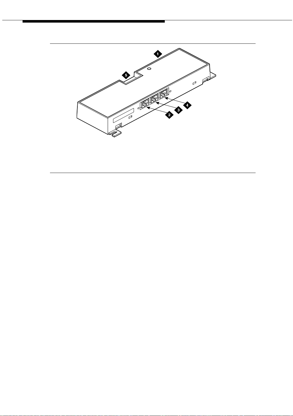
Figure 1 shows a typical 909A/B universal coupler. For additional installation and
switch setting information, refer to 909A/909B Universal Coupler Installation
Instructions.
NOTE:
If the music source is registered by the FCC (in the USA) or an equivalent
body, the 909A/B universal coupler is not required.
Issue 4 October 2002 25555-233-116
Page 26
909A/B universal coupler
1. 909A/B universal coupler
2. J1 8-pin modular jack
3. J2 8-pin modular jack
Figure 1. Typical 909A/B universal coupler
909_brkt KLC 042296
4. J3 7-pin modular jack
5. DIP switch location
The 909A is the direct current (DC) version of the coupler, and cabinet power
supplies -48 VDC power. The 909B is the alternating current (AC) version, and
power is supplied from a separate power supply (such as the KS-22911L2).
The DIP switches on the unit set:
■ Protection/Paging selection — For AUX trunk paging and malicious call
trace, set to C2. Set the switch to C1 for all other applications.
■ Output attenuation (-9 or -15 dBm) — Setting depends on output level of
music source.
■ Output impedance (8 ohms, 1.5 kΩ, and 50 kΩ) —This switch only
requires setting if the Protection/Paging switch is set to C2 and the coupler
is supplying background music to a customer-supplied paging amplifier.
The pinouts for J1, J2, and J3 are provided in Table 2, Table 3, and Table 4. Refer
to these tables when connecting music or paging equipment.
26 Issue 4 October 2002
555-233-116
Page 27

909A/B universal coupler
Table 2. J1 Pin Assignments (System Connections)
Pin Color Designation Description
1 White-Orange — Not Used
2 Orange PG2/BZ2 Seizure control lead, connected to -48 VDC from
the system or from the 909A/B when the protection
paging switch is set to C2, or to -48 VDC on the
909A/B when protection/paging switch is set to C1
3 White-Green PG1/BZ1 Seizure control lead, connected to SZ lead from
the AUX trunk when the protection/paging switch
is set to C2, or to -48 VDC on the 909A/B when the
protection/paging switch is set to C1
4 Blue R Ring lead
5 White-Blue T Tip lead
7 Green BSY2/BY2 Busy/busy-out lead, connected to S1 lead from the
AUX trunk
7 White-Brown BSY1/BY1 Busy/busy-out lead, connected to S lead from the
AUX trunk
8Brown — Not Used
Table 3. J2 Pin Assignments (Accessory Connections)
Pin Color Designation Description
1 White-Orange CMS1/M1 Customer-supplied music source
2 Orange CMS2/M2 Customer-supplied music source
3 White-Green COS1 Remote busy-out control contact closure from
music source
4 Blue CR Customer ring lead
5 White-Blue CT Customer tip lead
7 Green COS2 Remote busy-out control contact closure from
music source
7 White-Brown CBS1/C1 Seizure indication provided to music source
8 Brown CBS2/C2 Seizure indication provided to music source
!
CAUTION:
Do not plug the cable into J3 before all cross-connects are completed.
Damage to the 909A/B universal coupler may occur.
Issue 4 October 2002
27555-233-116
Page 28
909A/B universal coupler
2
Table 4. J3 Pin Assignments (Power Connections)
Pin Color Designation Description
1, 3, 4, & 7 —— Not used
2 Black GRD -48 RET or grou nd le ad fro m sys tem or
5 Yellow -48 VDC -48 VDC from system or from negative
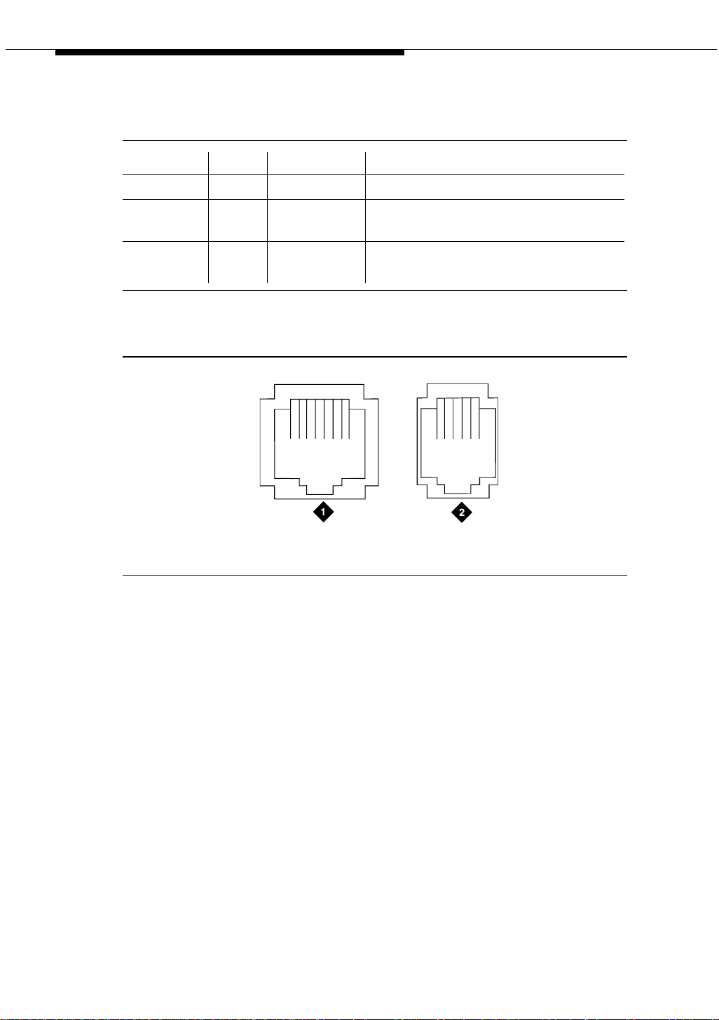
Figure 2 shows the physical locations of the pins for J1, J2, and J3.
from positive lead of power supply
lead of power supply
18
mod_jack RBP 041796
5
1. J1 and J2 8-pin modular jacks 2. J3 7-pin modular jack
Figure 2. Typical modular jack pinout
28 Issue 4 October 2002
555-233-116
Page 29

Auxiliary power supplies
Nonessential features of the attendant console, such as the optional 27B1
selector console as well as DCP terminals, derive their power from an auxiliary
power source. One console can connect to an Avaya DEFINITY
three consoles can connect to each cabinet stack on an Avaya DEFINITY
Server R.
2
®
Server CSI, and
®
Each cabinet can derive auxiliary power from the system and through the auxiliary
cable located in the trunk/auxiliary field. Auxiliary power for a primary attendant
console should be provided through this cable so the console remains fully
operational during short power outages.
NOTE:
The information in the first part of this chapter concerning auxiliary power
supplies for the gateway itself (page 30 through page 40) does not apply to
the G700 Media Gateway.
Information beginning on page 40, ‘‘1151A and 1151A2 power supplies’’,
does apply to a G700 Media Gateway under the following conditions:
■ if a particular endpoint or adjunct uses a 1151A or 1151A2 power
supply, and
■ if that endpoint or adjunct is supported on an S8300/G700.
Please see your Avaya representative for more information.
Issue 4 October 2002 29555-233-116
Page 30

Auxiliary power su pplies
Local auxiliary power supply
Consoles can use either local or phantom power, depending on the distance
between the console and the cabinet. Over short distances, phantom power is
attractive because no additional hardware is necessary—power is supplied using
the telephone circuit itself. For longer distances, you need a local power supply.
Table 5 shows cabling distances for the 302 attendant console.
Table 5. 302C1 Attendant Console Cabling Distances
24 AWG Wire
(0.27 mm
feet meters feet meters
With selector console:
Phantom-powered 800 244 500 152
Locally powered 5000 1524 3400 1037
Without selector console:
Phantom powered 1400 427 900 274
Locally powered 5000 1524 3400 1037
Applications that require auxiliary power
Auxiliary power (local or bulk) is alway s requi re d for the followi ng:
■ Any 8520 telephone
■ 302-series attendant console
■ Pass ag eWay adapter interfa ce
■ Any 7500-series telephone whether in passive bus, or point to point (one
per BRI port)
■ Any 7500- or 8500-series telephone with an asynchronous data module
■ Any 8510 telephone in passive bus or with an asynchronous data module
(unless the 8510 will not be used to support data or video)
■ Any 7400-series telephone with XM24 expansion module
■ Any 7400-series telephone with adjuncts 7407, 7434 or 7444
■ Any 8400-series telephone with adjuncts 8411 or 8434
■ Any 4600-series IP telephone
■ IP console
2
)
27 AWG Wire
(0.14 mm2)
The 1145B power supply is required for all installations outside the United States.
30 Issue 4 October 2002
555-233-116
Page 31

Sources of auxiliary local power
Sources of auxiliary local power
An attendant console can derive auxiliary power from:
■ A bulk power supply, such as the 1145B
A console’s maximum distance from its 1145B auxiliary powe r source is
800 ft. (244 m) for a 302A1 or 350 ft. (107 m) for a 301B1 and 302C1.
■ 1151A1 or 1151A2 power supply
Required safety precautions
!
DANGER:
When operating power-supply equipment, you must follow basic safety
precautions to reduce the risk of fire, electric shock, and personal injury.
Read and understand all instructions. Follow all warnings and instructions
marked on the products. Follow all the installation instructions when
mounting the product.
Never use a power unit with a power source other than that specified on the
product labels.
Do not try to plug the 3-wire grounding plug into a nongrounding power
outlet. This plug only fits into a grounding power outlet. This is a safety
feature. If you are unable to insert the plug into the outlet, have an electrician
replace the outlet. Do not defeat the safety purpose of the grounding plug.
Do not attach the power supply cord to building surfaces.
Do not overload power outlets.
Do not use this product near water. Do not let anything spill on or into the
unit. Clean only with a dry rag.
Never push objects through openings in the case.
Do not try to disassemble the unit. Return it for repair. Opening or removing
covers may expose you to dangerous voltages. Incorrect reassembly may
cause electric shock when the products are subsequently used.
Power down the unit and refer servicing immediately if the unit is exposed to
water or other liquids, if the unit is dropped or damaged, or if the unit fails to
operate normally.
Never let the operating temperature of the unit exceed the recommended
maximum.
Issue 4 October 2002
31555-233-116
Page 32

Auxiliary power su pplies
!
DANGER:
Do not block or cover the ventilation openings in the case.
Do not let anything rest on the unit.
Do not attempt to recharge batteries. The power unit recharges the batteries
itself. Any other recharging method may cause leaks of corrosive electrolyte
or explosion. Discard discharged batteries as soon as possible. Discharged
batteries are more likely to leak.
Do not store batteries in high temperature areas. Batteries stored in a cold
environment should be protected from condensation during storage and
warming. Batteries should be stabilized at room temperature prior to use
after cold storage. Do not install batteries if the manufacturing date on the
label indicates that the batteries are more than six months old.
1145B power supply
The 1145B power supply powers ISDN/DCP, terminal equipment, adjuncts, and
other customer-supplied external equipment. It supplies -48V, 200 W total and
supports 32 outputs. You can install one ISDN terminal or DCP adjunct per output.
A manual switch on the distribution unit lets the user redirect reserve power to
outputs 1 to 32 so that all outputs get battery reserve power.
An optional 1149 battery and 1146 distribution unit provides uninterruptible -48
VDC power.
!
DANGER:
When operating power-supply equipment, you must follow basic safety
precautions to reduce the risk of fire, electric shock and personal injury.
Read, understand, and follow all warnings and instructions. See ‘‘Required
safety precautions’’ on page 31.
Circuit protection
A thermistor current-limits the maximum output of each output to 12 W, but the
average power per output cannot exceed 7.25 W (200/32 = 7.25). An LED
indicates the status of the thermistor. When the LED is ON, there is a short on the
power pair.
32 Issue 4 October 2002
555-233-116
Page 33

1145B power supply
Mountings
The back-up battery mounts on a top plate. The power supply and distribution
units mount on a bottom plate. The plates are normally wall-mounted.
Installing the wall mounting
See Figure 3.
1. Locate one plate directly below the other with the raised letters right side
up. Be sure that the AC power cord can reach the electrical outlet from the
bottom plate. The power cord is about 7.5 ft. (2 m) long.
NOTE:
Up to 4 power supplies can draw current from one 110- or 230-VAC,
20- or 15-A feeder. Use only unswitched receptacles that are not
shared with other equipment.
2. Secure the wall mounting plates to a 3/4-in. (2-cm) plywood mounting
board using the four 1/2-in. #10 wood screws supplied with the plates.
3. Snap the 1145B power supply onto the bottom wall-mounting plate (no
tools are needed).
4. Connect an insulated 17-AWG #12 (1.2-mm) ground wire (or better)
between the ground lug on the power-supply frame and an approved
ground.
The frame ground screw is located next to the AC receptacle, to the left of
the unit.
5. Write the unit number and connectivity information on the front label, next
to the LEDs.
Issue 4 October 2002
33555-233-116
Page 34

Auxiliary power su pplies
1149 Battery
1145 Power Unit
4
2
On Battery Reserve
Charging Battery
Output Power On
1
3
1146 Power Distribution Unit
1-8
7
5
1-32
6
1. Wall mounting plate
2. Optional battery (1149B shown)
3. 1146 power distribution unit
4. 1145B power unit
Figure 3. 1145B/1146 mounting arrangement
34 Issue 4 October 2002
pcdf1145 KLC 030100
5. Power cable
6. Unswitched outlet (120 VAC, 20 A or 230
VAC, 15 A )
7. Battery backup switch setting
555-233-116
Page 35

1145B power supply
Installing the 1146 power distribution unit
1. Insert and securely tighten the two supplied #8-32 x 1/2-in. shoulder
screws (they have an unthreaded section at the top) into the top holes
designated for 1146 Power Distribution Unit on the bottom plate. Mount the
unit on these two shoulder screws, using the key holes on the back of the
unit.
2. Secure the unit by inserting the #8-32 x 1 in. screw through the bottom of
the unit (just above the wire clips) into the plate and tighten.
3. Set the battery back-up switch option to the 1-32 (down) position to provide
battery back-up to all outputs.
4. Connect the power distribution unit to the power supply with the power
cable. Refer to the power supply’s right-side label to locate the output
power connection.
Installing and wiring the battery
Two types of backup batteries can be used:
Table 6. Back-Up Batteries
Battery Rating
1148B 2.5 amp-hours
1149B 5 amp-hours
To install the battery, proceed as follows.
1. Loosely insert two #10-32 x 1/2-in. shoulder screws in the battery-mounting
holes at the top of the wall mounting plate.
2. Place the keyhole slots in the battery bracket on these two screws. Make
sure the label on the battery is visible.
The battery cord exits from the right side of the bracket.
3. Tighten the screws securely.
4. Plug the battery cord into the right rear receptacle on the power supply.
The right-side label indicates the rear receptacle.
Issue 4 October 2002
35555-233-116
Page 36

Auxiliary power su pplies
Installing the expanded power distribution unit
You can install a second power-distribution unit for additional 8400- and 8500series terminals.
!
CAUTION:
Total power cannot exceed 200 W. Consult the chart below for permissible
terminal installations.
Table 7. Permissible terminal installations (total power < 200 W)
Terminal mix Maximum numbers Notes
7500-series + 8500-series ISDN 24 + 24
7400-series + 8400-series DCP 24 + 24
8400-series DCP 74
7400-series DCP 74 Average power per
terminal must be
less than 3.126 W
Each expanded power distribution unit kit supplies the following items:
■ One power distribution unit
■ One T-cable
■ Two #8-32 x 1/2-in. shoulder screws
■ One #8-32 x 1 in. screw
■ One spacer bracket
See Figure 4 while installing the power distribution unit:
1. Fasten the spacer bracket to the mounting plate with the #8-32 x 1/2-in.
shoulder screws.
The spacer bracket is not shown in the figure. It is behind the top power
distribution unit.
2. Slide the keyhole slots in the power distribution unit over the shoulder
screws.
3. Insert the #8-32 x 1 in. screw through the distribution unit, through the
spacer bracket, and into the plate. Tighten the screw.
The mounting hole is located just above the wire clip.
4. Set the battery back-up switch to the 1-32 (down) position.
5. Power-down the 1145B as described on the label on the side of the unit.
36 Issue 4 October 2002
555-233-116
Page 37

1145B power supply
6
6. Remove the output power cable between the 1145B and the 1147B units.
The cable will not be reused.
7. Connect the P1 connector end of the T-cable to the bottom power
distribution unit.
8. Connect the P2 connector to the top distribution unit.
9. Connect the P3 connector to the 1145B.
10. Power-up the 1145B as described on the label on the side of the unit.
1149 Battery
1145 PowerUnit
On Battery Reserve
Charging Battery
Output Power On
1
2
3
4
5
6
7
8
9
10
11
12
13
14
15
16
1
2
3
4
5
6
7
8
9
10
11
12
13
14
15
16
-48V -48V
RTN RT N
-48V -48V
RTN RT N
UnitNo.
ConnectedTo:
UnitNo.
ConnectedTo:
17
18
19
20
21
22
23
24
25
26
27
28
29
30
31
32
17
18
19
20
21
22
23
24
25
26
27
28
29
30
31
32
1. Wall-mounting plate
2. Optional 1146 power distribution unit
3. T cable (H600-347-G7)
Figure 4. Expanded power distribution unit
0004_1 PDH 06259
4. Standard 1146 power
distribution unit
5. 1145B power unit
Issue 4 October 2002
37555-233-116
Page 38

Auxiliary power su pplies
Powering up and testing AC and DC power
When you power up the unit or interrupt power to a unit, the unit runs an AC or DC
self test. LEDs on the front panel indicate the status of the power supply. The
followin g table lists the LEDs.
Table 8. Power-supply LEDs
LED Color Meaning
GREEN Power supply is providing power
YELLOW Battery is charging (after at most 20 hours, when the battery has
reached full charge, the YELLOW LED should go out)
RED Power supply is on battery reserve
1. Connect the AC power cord to the power supply , and route the cord to an
appropriate AC outlet using the clips provided on the unit.
NOTE:
A maximum of four power supplies can be powered from one
dedicated 110 VAC, 20-A feeder. Use only unswitched receptacles.
2. Start the AC test by plugging the cord into the outlet.
This powers up the power supply.
3. Check AC operation of the 1145B power supply by monitoring the LEDs:
PASS: GREEN and YELLOW are both lit.
FAIL: either GREEN or YELLOW LED is not lit.
4. If the AC test failed, test the AC outlet, power cord, and connections.
5. If the AC test failed, but power is available and the AC power cord and
connections are good, replace the power unit.
6. Once the AC test passes, activate the DC battery-backup supply by
disconnecting the AC plug.
7. Check DC (battery back-up) operation by monitoring the LEDs.
PASS: RED and GREEN are both lit.
FAIL: either RED or GREEN is not lit.
8. If the DC test fails, check the connections.
9. If the DC test fails but the connections are good, replace the batteries and
retest.
10. If the DC test fails after you replace the batteries, replace the power supply.
11. Once the DC test passes, reconnect AC power to the power supply.
38 Issue 4 October 2002
555-233-116
Page 39

1145B power supply
Wire the 1146 power distribution unit
Wire endpoints to the 1146 while power from the 1145B is on.
1. Install cross-connect jumpers (the label shows polarity) to Pins 7 and 8 of
the appropriate information outlet. Route the wires through the clip
provided on the unit. If a red LED is on, see ‘‘Repairing short circuits and
resetting red LEDs’’ on page 40. Figure 5 shows the co nnec ti ons .
A red LED lights if the associated circuit is connected to shorted wiring or a
shorted terminal.
1
2
11
12
7
4
1. Power supply kit
2. 2.5, 5.0, or 8.0 A hour battery
3. 1146 power distribution unit
4. 1145B power supply
5. Circuits 1-17
6. Circuits 17-32
7. Port circuit
3
14
5
6
14
8
10
9 9
8. Main distribution frame
9. Modular cord
10. AC input
11. Ground wire
12. ISDN/ display system protocol terminal
13. Circuits 1-32
14. Pins 7 and 8 (display terminal power)
13
Figure 5. Typical wiring to a terminal
2. Mark lead destinations, unit number, and connectivity information on the
label next to each connector.
Issue 4 October 2002
39555-233-116
Page 40

Auxiliary power su pplies
Replacing the batteries
To maintain back-up protection and battery reliability, replace batteries every four
years.
Storing the batteries in inactive units
To prevent leakage when the power unit is not in use for several months or more,
remove the batteries and store them separately.
Repairing short circuits and resetting red LEDs
A red LED next to any of the 32 power output connectors indicates a short circuit
in the building wiring or the terminal equipment. To reset the LED:
1. Disconnect the terminal equipment from the wall jack.
2. If the LED goes off, the terminal equipment is faulty. Replace it.
3. If the LED is still lit, find and repair the short circuit in the building wiring.
4. Reconnect the terminal equipment to the wall jack, and re-test.
1151A and 1151A2 power supplies
The 1151A is a standard (no battery backup) power supply unit. The 1151A2 is a
battery backup version of the 1151A. Either power supply can support one
telephone with or without an adjunct.
The 1151A and 1151A2 power supplies can supply local power to ISDN-T 7400-,
7500-, 8400-, and 8500-series voice terminals connected to a system, and to the
DCP 7444 voice terminal or 302C attendant console that need auxiliary power for
its display. The unit can supply power to adjunct equipment such as S201A and
CS201A speakerphones, or a 500A headset adapter attached to any currently
manufactured analog, DCP, or ISDN-T voice terminal equipped with an adjunct
jack.
The power supply has the following specifications:
■ A single output of -48 VDC, 0.4 A.
■ Either a 120 VAC 60-Hz power source (105 to 129 VAC) or a 220/230/240
VAC 50-Hz power source (198 to 274 VAC).
■ Automatic input voltage selection.
■ Output capacity of19.2 W.
■ Maximum loop range of 250 ft. (77 m).
■ Use of 2 modular jacks. PHONE jack pins 7 and 8 (- and +, respectively)
provide power.
40 Issue 4 October 2002
555-233-116
Page 41

1151A and 1151A2 power supplies
The PHONE and LINE jacks are 8-pin female nonkeyed 757-type jacks that can
accept D4, D7, and D8 modular plug cables. Figure 6 shows a 1151A power
supply. The 1151A2 looks similar.
!
DANGER:
When operating power-supply equipment, you must follow basic safety
precautions to reduce the risk of fire, electric shock and personal injury.
Read, understand, and follow all warnings and instructions. See ‘‘Required
safety precaution s’’ on page 31.
!
CAUTION:
Do not locate the unit within 7 in. (15.25 cm) of the floor.
Use the power supply only with telecommunications equipment, indoors,
and in a controlled environment.
pwr_sup1 CJL 051496
Figure 6. Typical 1151A power supply (front)
Issue 4 October 2002
41555-233-116
Page 42

Auxiliary power su pplies
Desk mounting
1. Place the power supply on a flat surface such as a desk.
Wall mounting
1. For wall-mounting, use the keyhole slots on the bottom of the chassis.
Standards compliance
The 1151A and 1151A2 power supplies comply with the UL Standard UL 1459,
second edition.
Table 9. Standards compliance
Complies UL 1459
Certified CSA 22.2
Approved EN7950
Approved CE
42 Issue 4 October 2002
555-233-116
Page 43

Extenders for 2-wire DCP endpoints
This chapter provides information on 2-wire voice and data terminals and digital
communications protocol (DCP) extenders. Extenders provide off-site employees
with the full feature set of the PBX.
3
2-wire DCP endpoints
Wire the tip and ring connections of 2-wire DCP endpoints to a TN2224B digital
line 2-wire circuit pack (or equivalent), similar to the 2-wire analog endpoints for a
TN747B analog line circuit pack.
The TN2224B supports 2-wire DCP sets only (not 4-wire).
The MM712 media module for the G700 Media Gateway is a 2-wire DCP
interface. The G700 Media Gateway supports 2-wire DCP sets only (not 4-wire).
!
CAUTION:
Except for auxiliary power, if necessary, these should be the only
connections to the modular wall jack. Do not bridge or parallel these
telephones.
Table 10 provides the pin-out configuration for 2-wire endpoints.
Issue 4 October 2002 43555-233-116
Page 44

Extenders for 2-wire DCP endpoints
Table 10. Pin-out for 2-wire DCP endpoints
Pin Number Function
1 not used by 2-wire DCP endpoints
2 not used by 2-wire DCP endpoints
3 not used by 2-wire DCP endpoints
4 DCP signal transmission
5 DCP signal transmission
6 not used by 2-wire DCP endpoints
7 auxiliary power -48 VDC (if needed)
8 auxiliary power ground (if needed)
Figure 7 shows a workstation connecting to a data adapter. The line side of the
adapter connects to the TN2181 digital line 2-wire circuit pack through the main
distribution frame (MDF) (to the system cabinet).
1
7
itdata RBP 032896
5
5
Line
3
1. 103A or modular wall jack
2. 2-wire endpoint
3. Data terminal (serial data)
4. Data adapter (such as an 8400B+)
2
Phone
4
I/O
6
5. 4-wire modular cord
6. Serial data cable
7. To TN2181 digital line circuit pack
Figure 7. Typical connections to a 2-wire DCP workstation
44 Issue 4 October 2002
555-233-116
Page 45

DCP extender, stand alone
Wire the circuit pack to the MDF with a 25-pair cable:
1. Wire to the data adapter per local standards.
2. Wire the data terminal and telephone as instructed in the document
accompanying the data adapter.
DCP extender, stand alone
The stand alone extender installs at the work location. See Appendix A, Table 33,
‘‘DCP extender 25-pair cable pinout’’ for cabling information and pin assignments.
NOTE:
2-wire DCP extenders are not currently supported on G700 Media Gateway
configurations.
Figure 8 shows a typical connection from a digital line 2-wire DCP circuit pack
through two DCP extender devices. The DEFINITY Extender Switch Module
System Administrator’s Guide contains additional information.
1. Avaya™ Media Server/Gateway
2. TN2181 or TN2224B circuit pack
3. 25-pair cable
4. DCP extender
5. Main distribution frame (MDF)
6. Pub lic swit ch ed tele pho ne netwo rk (P STN)
Figure 8. Typical DCP extender connections
7. 103A or modular wall jack
8. Modular line cord
9. DCP telephone (Such as 8410D,
8405, or 8434)
10. Remote work location
Issue 4 October 2002
45555-233-116
Page 46

Extenders for 2-wire DCP endpoints
DCP extender, rack mount
Figure 9 shows a typical rack mount (multi-mount) DCP extender. Connections
from either a digital line 17-port 2-wire DCP circuit pack or a digital line 24-port
2-wire DCP circuit pack, are made through two DCP extender devices.
NOTE:
2-wire DCP extenders are not currently supported on G700 Media Gateway
configurations.
h2dferm PDH100796
1. Front of rack mount assembly
2. First circuit pack in slot 1 (“A”)
3. Slot 12 (“L”)
Figure 9. Typical DCP extender connections
4. Rear of rack mount assembly
5. 25-pair connector to the MDF and the digital
6. Power connector
46 Issue 4 October 2002
line circuit packs
555-233-116
Page 47

Data modules and asynchronous data units
Data modules connect peripheral equipment to the Avaya Media Server or
Gateway or the Avaya S8100 Media Server with a CMC1 Media Gateway
(DEFINITY ONE). Data modules convert between the RS-232 communications
protocol used by peripherals and the digital communications protocol (DCP).
4
Possible peripherals include AUDIX adjunct equipment and terminals, serial
printers, customer-supplied terminals and host computers, call detail recording
(CDR) devices, and pooled modems.
NOTE:
Data modules, PGATE boards, printers connected through data modules,
SATs connected through data modules, and anything related to the X.25
connectivity protocol are not supported on the S8300 or S8700 Media
Server platforms.
The following data modules are described in this chapter, and Figure 10 shows
typical data-module connections.
■ 7400A/B/C/D
■ 8400B
■ ExpressRoute 1000
■ Asynchronous data units (ADU).
NOTE:
ISDN data modules, such as the 7500B, are not covered in this book. Refer
to Integrated Services Digital Network (ISDN) 7500B Data Module User’s
Manual, for detailed procedures. ISDN data modules connects DTE and
DCE equipment to the ISDN network using an RS-232 or V.35 interface and
an RS-377 automatic calling unit.
Issue 4 October 2002 47555-233-116
Page 48

Data modules and asynchronous data units
Understanding RS-232 communications
To install a data module, you have to set up the device to work with RS-232
devices.
NOTE:
Data modules, PGATE boards, printers connected through data modules,
SATs connected through data modules, and anything related to the X.25
connectivity protocol are not supported on the S8300 or S8700 Media
Server platforms.
The RS-232 communications protocol defines a communications link as a Data
Communications Equipment (DCE) device and a Data Terminal Equipment (DTE)
device connected by an RS-232 cable. The send and receive pins on DCE
equipment (pins 2 and 3) are reversed on DTE equipment, so that the DCE
transmit pin connects to the receive pin of the DTE and vice versa.
Generally, the term DCE is applied to devices that mediate between customer
equipment and the carrier or network. Such devices include modems, data
modules, and data units. DTE describes devices that provide a user interface for
data communications, such as dumb terminals and PCs. When configured as
DTE, data modules are used for asynchronous modem pooling. When configured
as DCE, data modules are analogous to modems in that they link a device such
as a terminal or PC (DTE) to DEFINITY.
To install a data module correctly, you identify the connected equipment as DCE
or DTE and do one of the following:
■ Configure the modem for a DTE or DCE connection
■ Install a null-modem converter
Detailed instructions are provided for each modem type, beginning on page 49.
48 Issue 4 October 2002
555-233-116
Page 49

Installation procedure
cydfnst RPY 070397
1. 103A connector or modular wall jack
2. 400B2 adapter
3. Rear of data module (7400B Shown)
4. Host computer
5. Data module power supply
6. Electrical outlet
7. Dis play tel eph one
8. S101A speakerphone
Port 2
Phone
Line
Power Port 1
9. Auxiliary power supply for telephone
10. D7AP cord
11. D8W cord
12. Line to display telephone (D8W cord)
13. Data cable (EIA/RS-232)
14. Data-module power cable
15. To MDF and system cabinet
16. Printer
Figure 10. Typical connections to a data module
Installation procedure
To install a typical data module, you perform the following tasks:
1. Obtain required equipment
2. Set hardware options (must be completed before you administer or
physically connect the data module)
3. Connect data modules
4. Administer the data modules (can be completed either before or after you
physically connect the data module)
Issue 4 October 2002
49555-233-116
Page 50

Data modules and asynchronous data units
Obtain required equipment
To physically connect a data module to the system, you need the following parts.
■ 105C/D Isolating Data Interface (if connecting to a DC cabinet).
■ EIA-232-D (RS-232-C) cable with a male connector (for the data module)
and the correct connector for the peripheral equipment.
The cable connects the PC to the data module.
■ Null-modem converter (optional).
■ V.35 cable with correct connectors (not required by all systems).
■ D8W telephone cord.
The cord connects the data module’s LINE jack to the DEFINITY wall jack.
■ DCP telephone and D8W cord (optional).
The D8W cord connects the telephone to the data module’s PHONE jack.
■ Suitable auxiliary power supply if the optional telephone is installed (D7AP
power cord and 400B2 adapter in the US, international power supply, such
as the MSP-1, elsewhere).
You must have access to the administration console of the DEFINITY, either
through a terminal and keyboard or through a PC.
A breakout box for RS-232 interfaces may prove helpful in some cases. The RS232 breakout box helps you to identify the pin configuration of the RS-232
interface on the equipment you are trying to connect.
Set hardware options
Depending on the data module, you may have to set various configuration options
using hardware switches, software commands, or both. You must set the
hardware options before you administer or physically install the data module.
Setting 7400A data module hardware options
Most configuration options are controlled by commands entered on the front panel
of the 7400A. But you have to make hardware changes when you want to set up
the 7400A data-module for use in a modem pool or as a piece of data
communications equipment. In a modem-pool, the data module operates as dataterminal equipment (DTE). In most other applications, it functions as data
communications equipment (DCE). Y ou have to set the correct operating mode for
the data module before you can access the menus for the remaining configuration
tasks.
50 Issue 4 October 2002
555-233-116
Page 51

Set hardware options
To change the operating mode of the 7400A from DCE to DTE (or vice versa), you
change the position of a small circuit board (the Electronic Industries Association
connector board) inside the case. See Figure 11 and proceed as follows.
!
WARNING:
Electrostatic discharge can severely damage sensitive electronic circuits.
Before handling any electronic hardware, be sure to wear a grounding wrist
strap or other static-dissipating device. Do not touch exposed circuitry or
semiconducto r chi ps .
1. Unplug the data module from the power receptacle.
2. Remove the access panel on the top of the case by grasping the rear lip of
the panel and pulling sharply upward.
3. While facing the front of the data module, locate the small EIA connector
circuit board. It sticks up vertically, and a large, silver arrow on the main
circuit board points to it.
DTE
HOME
NEXT/NO BACK ENTER/YES
POWERTEST
7400A Data Module
DATA
7400atop KLC 053096
1. 7400A data module 2. EIA connector board (shown in DTE mode)
Figure 11. Data module mode selector
4. Note the three letters engraved in the upper lefthand corner of the EIA
connector board. Data modules ship from the factory with board inserted
with “DCE” in the upper left corner.
Issue 4 October 2002
51555-233-116
Page 52

Data modules and asynchronous data units
596
5. Use the DCE position to connect to DTE equipment. Use the DTE position
to connect to DCE equipment. To change the mode, remove the board by
grasping it and pulling it gently upward. Flip the board around, left to right,
and reinsert it in the socket so that the correct operating mode, DCE or
DTE, appears in the upper lefthand corner.
6. Snap the top cover onto the unit.
Setting 7400B data module hardware options
You configure the 7400B data module using DIP switches on the circuit card
inside the case. Figure 12 shows the front and rear of a 7400B data module.
DATA
METERING
POWER
TEST
PHONE
AA CD RD SD TR OH
7400B D ata Mod u le
LINE
POW ER
CHECK
SPEED
DATA
PORT 2
PORT 1
7400bRBP032
Figure 12. 7400B data module
To configure the 7400B data module, proceed as follows.
!
WARNING:
Electrostatic discharge can severely damage sensitive electronic circuits.
Before handling any electronic hardware, be sure to wear a grounding wrist
strap or other static-dissipating device. Do not touch exposed circuitry or
semiconducto r chi ps .
1. If you are not attaching a telephone to the data module, activating data
metering, or enabling busyout on the local loop, you can use the factory
default settings. The 7400B data module is already configured for your use.
Stop now.
52 Issue 4 October 2002
555-233-116
Page 53

Set hardware options
2. Otherwise, remove the access panel on the top of the case by grasping the
rear lip of the panel and pulling sharply upward.
3. Locate the DIP switch block, a bank of tiny switches on the circuit board, in
the center of the opening.
DIP switches 1, 5, and 8 control the attached telephone (if any), data
metering, and loopback on local loop.
4. Set the switches for the combination of options that you need to enable,
using the chart below as a guide.
No telephone attached, data metering OFF, busyout on local loop OFF
(factory default settings)
O
N123456789
DOWN DOWN DOWN DOWN DOWN DOWN DOWN DOWN DOWN
Telephone attached, data metering OFF, busyout on local loop OFF
O
N123456789
UP
DOWN DOWN DOWN DOWN DOWN DOWN DOWN DOWN
No telephone attached, data metering ON, busyout on local loop OFF
O
N123456789
UP
DOWN DOWN DOWN DOWN DOWN DOWN DOWN DOWN
No telephone attached, data metering OFF, busyout on local loop ON
O
N123456789
UP
DOWN DOWN DOWN DOWN DOWN DOWN DOWN DOWN
Issue 4 October 2002
53555-233-116
Page 54

Data modules and asynchronous data units
No telephone attached, data metering ON, busyout on local loop ON
O
N123456789
DOWN DOWN DOWN DOWN DOWN DOWN DOWN
Telephone attached, data metering ON, busyout on local loop OFF
O
N123456789
UP UP
DOWN DOWN DOWN DOWN DOWN DOWN DOWN
Telephone attached, data metering OFF, busyout on local loop ON
O
N123456789
UP UP
UP UP
DOWN DOWN DOWN DOWN DOWN DOWN DOWN
Telephone attached, data metering ON, busyout on local loop ON
O
N123456789
UP UP UP
DOWN DOWN DOWN DOWN DOWN DOWN
5. Replace the cover on the data module.
Connect data modules
To connect a single data module, follow the procedure in following section. To
connect multiple data modules, see Connecting multiple data modules to the
system.
54 Issue 4 October 2002
555-233-116
Page 55

Connect data modules
Connecting a single data module
!
CAUTION:
You must install a 105D or 105C isolating data interface adapter when
connecting data modules to equipment in DC-powered cabinets.
Connect the data module to your house wiring or DEFINITY as follows.
1. Attach a D8W cable to the LINE port of the data module.
2. If you are going to attach a telephone to the data module
a. Attach a 400B2 adapter to the other end of the D8W cable.
b. Plug the adapter into a modular wall jack or 103A connector.
c. Plug a D7AP cord into the 400B2 adapter.
d. Plug the other end of the D7AP cord into the auxiliary power supply
for the telephone.
You must have a separate power supply for the telephone and for
the data module.
e. Attach a D8W cable to the PHONE port of the data module.
3. If you are not attaching a telephone, attach the D8W cable from the Line
port of the data module to a modular wall jack or 103A connector.
4. Attach the data-module power supply to the power connector on the back
of the data module, and plug the power supply into an AC electrical outlet.
5. Connect an RS-232 cable to the PORT 1 connector on the back of the data
module.
6. If the equipment includes a V.35 interface, plug a V.35 cable into the V.35
connector on the data module.
7. If the data module is a 7400B DCE-only device and if the other end of the
cable is connected to another DCE device, insert a null-modem adapter
between the data module and the RS-232 cable.
8. Connect the other end of the RS-232 cable to a serial (COM) port
connection on the data device (host computer, serial printer, modem, etc.).
9. Go to the configuration procedure for the data module you are using:
■ Installation procedure
■ Configuring the 7400B Data Module
■ Configuring the 7400C HSL (high- speed link) data module
■ Configuring the 7400D data module
■ Configuring the 8400B Plus data module
■ Configuring the ExpressRoute 1000 data module
Issue 4 October 2002
55555-233-116
Page 56

Data modules and asynchronous data units
Connecting multiple data modules to the system
!
CAUTION:
You must install a 105D or 105C isolating data interface adapter when
connecting data modules to equipment in DC-powered cabinets.
You install multiple data modules in a data mounting on the DEFINITY. A Z77A
data mounting can take up to 8 data modules. See Figure 13.
1. Z77A data mounting
2. Data module (7400A shown)
3. Retaining bar
Figure 13. Z77A data mounting
Proceed as follows.
1. Set data-module hardware options before installing the hardware in the
mounting.
2. Release the horizontal retaining bar at the front of the data mounting by
pulling out the plungers at the left and right sides of the bar.
3. Pull the retaining bar out and down.
56 Issue 4 October 2002
z77a KLC 053096
4. Retaining bar plunger
5. Twist-lock cable retainers
555-233-116
Page 57

Connect data modules
4. Connect the a 25-pin RS-232 cable to the 25-pin connector on the rear of
the data module.
5. Route the cable through the data mounting and through the twist-lock cable
retainer on the top of the data mounting.
6. Attach the other end of the RS-232 cable to DTE or DCE.
7. Insert the data module vertically into the data mounting. Be sure the display
is to the top of the data mounting.
8. Repeat steps 2 through 5 for each data module.
9. Return the horizontal retaining bar to its original position to secure the data
modules inside the data mounting.
10. Go to the configuration procedure for the data module you are using:
■ Configuring the 7400A data module
■ Configuring the 7400B Data Module
■ Configuring the 7400C HSL (high- speed link) data module
■ Configuring the 7400D data module
■ Configuring the 8400B Plus data module
Configuring the 7400A data module
The 7400A is a full-duplex, asynchronous data module for use with Digital
Communications Protocol (DCP). It is designed for applications that do not require
integration of voice and data. It supports asynchronous connections at speeds up
to 19.2 Kbps through an EIA-232-D interface. Figure 14 represents the front and
back of the 7400A data module.
Issue 4 October 2002
57555-233-116
Page 58

Data modules and asynchronous data units
Figure 14. 7400A asynchronous data module
Using the 7400A menu system
On the 7400A, you select communications settings using the controls on the front
panel of the device. An LCD displays the configuration menus. You use the
NEXT/NO and BACK buttons to navigate through the menus and the ENTER/
YES button to select values.
Powering up the 7400A
When you power up the 7400A, the POWER TEST and DATA LEDs light up, and
the 7400A data module displays the HOME screen on the LCD. The figure below
represents a typical home screen. Dashes indicate a lead that is connected, ovals
a lead that is not.
58 Issue 4 October 2002
555-233-116
Page 59

Connect data modules
POWER
TEST
✹
Adjusting the control-panel display on the 7400A
1. Adjust the contrast of the display so that you can see it comfortably. Press
the ENTER/YES button. This steps you through the available contrast
settings.
D
D
SRR
T
R
0 0 —00 0——
D
C
D
I
7400A Data Module
T
S
TSTDR
D HOME
C
R
DATA NEXT/NO BACK ENTER/YES
✹ ❍❍❍
0 0 —00 0——
DATA NEXT/NO BACK ENTER/YES
● ❍❍➜ ●
Push the button indicated by the arrow (➜)
7400A data module, EIA RS-232 interface circuits
The data module communicates with other equipment through a configurable, 25pin RS-232 serial interface. DCE and DTE operation use different sets of pins and
assign different functions to some of the same pins. To avoid confusion later on,
please take a moment to review the differences. See the table below (the pins
most discussed in subsequent sections have been emphasized).
Pin Name Function DCE DTE
1 — Not used ——
2 BA (TD) Transmitted Data Input Output
3 BB (RD) Received Data Output Input
4 CA (RTS) Request to Send Input Output
5 CB (CTS) Clear to Send Output Input
6 CC (DSR) Data Communication Equipment Ready Output Input
7 AB (SG) Signal Ground Common Common
8 CF (RLSD) Received Line Signal Detector Output Input
Continued on next page
Issue 4 October 2002
59555-233-116
Page 60

Data modules and asynchronous data units
Pin Name Function DCE DTE
9 — Reserved for Testing +12 volts —
10 — Reserved for Testing -12 volts —
11 — Not used — —
12 CI Data Signal Rate Select (DCE Source) Output Input
13 CI2 Data Signal Rate Select 2 (DCE Source) — Input
14 — Not used — —
15 DB* Transmitter Signal Element Timing (DCE
Source)
16 — Not used — —
17 DD* Receiver Signal Element Timing (DCE
Source)
18 LL Local Loopback Input Output
19 CH2 Data Signal Rate Select 2 (DTE Source) — Output
20 CD (DTR) Data Terminal Equipment Ready Input Output
21 RL Remove Loopback Input Output
22 CE (RI) Ring Indicator Output Input
23 CH Data Signal Rate Select (DTE Source) Input Output
24 DA* Transmit Signal Element Timing (DTE
Source)
25 TM Test Mode O utput Input
* Circuits are not used for asynchronous operation. Outputs are clamped OFF and inputs are ignored.
Output Input
Output Input
Input Output
Continued on next page
Configuring the 7400A for data communications equipment (DCE) applications
If you are not going to use the 7400A data module in a modem pool, proceed as
follows.
60 Issue 4 October 2002
555-233-116
Page 61

Connect data modules
Setting interface options on 7400A DCE
1. To access the menus, press the NEXT/NO button.
00— 00 0——
DATA NEXT/NO BACK ENTER/YES
● ❍❍➜ ●
Push the button indicated by the arrow (➜)
2. When the SET OPTIONS? prompt appears on the LCD. Press the NEXT/
NO button.
SET OPTIONS?
DATA NEXT/NO BACK ENTER/YES
●➜ ● ❍ ❍
Push the button indicated by the arrow (➜)
3. The VIEW OPTIONS? prompt appears. Press the NEXT/NO button.
VIEW OPTIONS?
DATA NEXT/NO BACK ENTER/YES
●➜ ● ❍ ❍
Push the button indicated by the arrow (➜)
You will return to the options menus in a minute. But first you must select a
command interface for the data module.
4. The SET INTERFACE? prompt appears. Press the ENTER/YES button.
SET INTERFACE ?
DATA NEXT/NO BACK ENTER/YES
● ❍❍➜ ●
Push the button indicated by the arrow (➜)
A series of INT = InterfaceType? prompts appears.
Issue 4 October 2002
61555-233-116
Page 62

Data modules and asynchronous data units
5. For eac h pr omp t, if you w ant t o se lect t he i nte rfa ce, pres s th e ENTER/YES
button or, if you want a different interface, press the NEXT/NO button.
a. Enable the answer-only interface if the data module must operate
without any kind of external control:
INT=ANS ONLY?
DATA NEXT/NO BACK ENTER/YES
● ❍❍ ❍
Select an option (NEXT/NO or ENTER/YES)
b. Enable the AT-command interface if users need to control the data
module remotely, using a dial-up connection and Hayes-compatible
modem commands:
INT = AT COM?
DATA NEXT/NO BACK ENTER/YES
● ❍❍ ❍
Select an option (NEXT/NO or ENTER/YES)
c. Enable the keyboard-dial interface if users need to control the data
module interactively, from a terminal:
INT = KYBD DIAL?
DATA NEXT/NO BACK ENTER/YES
● ❍❍ ❍
Select an option (NEXT/NO or ENTER/YES)
After you select an interface, the data module runs a self-test and returns
to the HOME screen.
D
T
R
POWER
TEST
00— 00 0——
✹
62 Issue 4 October 2002
D
SRR
D
R
C
I
7400A Data Module
T
D
S
C
TSTDR
D HOME
DATA NEXT/NO BACK ENTER/YES
✹ ❍❍❍
555-233-116
Page 63

Connect data modules
Setting speed options on 7400A DCE
1. Press the NEXT/NO button to continue with the setup procedure.
00— 00 0——
DATA NEXT/NO BACK ENTER/YES
●➜ ● ❍ ❍
Push the button indicated by the arrow (➜)
2. The SET OPTIONS? prompt appears on the LCD. Press the ENTER/YES
button.
SET OPTIONS?
DATA NEXT/NO BACK ENTER/YES
● ❍❍➜ ●
Push the button indicated by the arrow (➜)
A series of SET number SPEED? prompts appears .
3. Press the NEXT/NO button until you see the SET 9600 SPEED? prompt.
Then press the ENTER/YES button.
SET 9600 SPEED?
DATA NEXT/NO BACK ENTER/YES
● ❍❍➜ ●
Push the button indicated by the arrow (➜)
Most DEFINITY connections operate at the 9600 speed.
4. The 9600 = ON? prompt appears. Press the ENTER/YES button.
9600=ON?
DATA NEXT/NO BACK ENTER/YES
● ❍❍➜ ●
Push the button indicated by the arrow (➜)
5. The CONTINUE? prompt appears. Press the ENTER/YES button.
CONTINUE?
DATA NEXT/NO BACK ENTER/YES
● ❍❍➜ ●
Push the button indicated by the arrow (➜)
Issue 4 October 2002
63555-233-116
Page 64

Data modules and asynchronous data units
6. The SET 19200 SPEED? prompt appears. Press the NEXT/NO button.
SET 19200 SPEED?
DATA NEXT/NO BACK ENTER/YES
●➜ ● ❍ ❍
Push the button indicated by the arrow (➜)
7. If you selected the AT-command int erface in the section ‘‘Setting interface
options on 7400A DCE’’, you are finished configuring the 7400A data
module.
Setting the automatic-answer feature on 7400A DCE
You can set up the 7400A data module to automatically answer calls or you can
have it ignore calls until an operator answers manually. Set up the data module for
automatic answering unless specifically directed to otherwise.
1. When t he SET ANSWER? prompt appears, press the ENTER/YES button.
SET ANSWER?
Push the button indicated by the arrow (➜)
2. When the ANS = AUTO? prompt appears, if you want to enable automatic
answering, press the ENTER/YES button. Otherwise, press the NEXT/NO
button.
DATA NEXT/NO BACK ENTER/YES
● ❍❍➜ ●
ANS = AUTO?
Select an option (NEXT/NO or ENTER/YES)
3. If you pressed NEXT/NO in the preceding step, the ANS —> MANUAL?
prompt appears. If you want to disable automatic answering, press the
ENTER/YES button. Otherwise, press the NEXT/NO button.
ANS —> MANUAL?
Select an option (NEXT/NO or ENTER/YES)
64 Issue 4 October 2002
DATA NEXT/NO BACK ENTER/YES
● ❍❍ ❍
DATA NEXT/NO BACK ENTER/YES
● ❍❍ ❍
555-233-116
Page 65

Connect data modules
4. The CONTINUE? prompt appears. Press the ENTER/YES button.
CONTINUE?
DATA NEXT/NO BACK ENTER/YES
● ❍❍➜ ●
Push the button indicated by the arrow (➜)
Setting the break-disconnect option on 7400A DCE
This setting specifies the length of the BREAK signal, a string of 10 or more
spaces that tells the host that the user needs to interrupt operations. There are
three options: TRIPLE, LONG (the default), and NONE. Accept the default values,
unless otherwise instructed.
1. When the SET BREAK DISC? prompt appears, press the NEXT/NO
button to keep the default.
SET BREAK DISC?
DATA NEXT/NO BACK ENTER/YES
●➜ ● ❍ ❍
Push the button indicated by the arrow (➜)
Configuring the RS-232 interface on 7400A DCE
You can set each pin of the RS-232 cable to meet the needs of specific
applications or connected equipment. however, in most cases, you can use the
defaults.
To set the EIA leads, proceed as follows:
1. When the SET LeadName LEAD? prompt appears, press the NEXT/NO
button to keep the default or the ENTER/YES button to make a change.
SET LeadName LEAD?
DATA NEXT/NO BACK ENTER/YES
●➜ ● ❍ ❍
Push the button indicated by the arrow (➜)
Issue 4 October 2002
65555-233-116
Page 66

Data modules and asynchronous data units
2. If you pressed the ENTER/YES button at the SET LeadName LEAD?
prompt, the LeadName -> ON? prompt appears. Press the ENTER/YES
button.
LeadName -> ON?
DATA NEXT/NO BACK ENTER/YES
● ❍ ❍➜ ●
Push the button indicated by the arrow (➜)
3. Repeat until all leads have been set.
Setting parity on 7400A DCE
Next you need to identify the type of parity coding that the data module should
expect. Parity is an error-detection scheme that is based on the value of a parity
bit in each unit of information. Four coding schemes are used: ODD, EVEN,
MARK, and SPACE. In odd-parity coding, the parity bit is set to 0 if the number of
1s in the information is odd, 1 if it is even. In even-parity coding, the parity bit is
set to 0 if the number of 1s in the information is even, 1 if it is odd. Mark-parity
coding always sets the parity bit to 1. Space-parity coding always sets the parity
bit to 0.
1. Accept the default value, unless otherwise instructed. When the SET
PARITY? prompt appears, press the NEXT/NO button to keep the default,
SPACE.
SET PARITY?
Push the button indicated by the arrow (➜)
DATA NEXT/NO BACK ENTER/YES
●➜ ● ❍ ❍
Enabling remote loopback testing on 7400A DCE
You can set the remote loopback option to GRANT or DENY.
1. Accept the default value, unless otherwise instructed. When the SET
REMOTE LOOP? prompt appears, press the NEXT/NO button to keep the
default, GRANT.
SET REMOTE LOOP?
Push the button indicated by the arrow (➜)
66 Issue 4 October 2002
DATA NEXT/NO BACK ENTER/YES
●➜ ● ❍ ❍
555-233-116
Page 67

Connect data modules
Configuring the ring indicator on 7400A DCE
The ring-indicator (pin 22) setting can have either of two values: CYCLE or ON
(the default).
1. Accept the default values, unless othe rw is e ins tru ct ed. Whe n the SET RI
LEAD? prompt appears, press the NEXT/NO button to keep the default,
ON.
SET RI LEAD?
DATA NEXT/NO BACK ENTER/YES
●➜ ● ❍ ❍
Push the button indicated by the arrow (➜)
Enabling remote loopback on 7400A DCE
The remote-loopback setting (pin 21) can have either of two values: ON or OFF
(the default).
1. Accept the default values, unless othe rw is e ins tru ct ed. Whe n the SET RL
LEAD? prompt appears, press the NEXT/NO button to keep the default,
ON.
SET RL LEAD?
DATA NEXT/NO BACK ENTER/YES
●➜ ● ❍ ❍
Push the button indicated by the arrow (➜)
Setting the signals-disconnect (SIGLS DISC) option on 7400A DCE
The settings can have either of two values: ON (the default) or OFF.
Accept the default values, unless otherwise instructed.
1. When the SET SIGLS DISC? prompt appears, press the NEXT/NO button
to keep the default, ON.
SET SIGLS DISC?
DATA NEXT/NO BACK ENTER/YES
●➜ ● ❍ ❍
Push the button indicated by the arrow (➜)
Issue 4 October 2002
67555-233-116
Page 68

Data modules and asynchronous data units
Enabling test mode on 7400A DCE
The test-mode (pin 25) setting can have either of two values: ON or OFF (the
default).
1. Accept the default values, unless otherwise instructed. When the SET TM
LEAD? prompt appears, press the NEXT/NO button to keep the default,
ON.
SET TM LEAD?
DATA NEXT/NO BACK ENTER/YES
●➜ ● ❍ ❍
Push the button indicated by the arrow (➜)
Exiting menus and saving changes on 7400A DCE
1. When the DONE? prompt appears, press the ENTER/YES button.
DONE?
Push the button indicated by the arrow (➜)
2. When the SAVE CHANGES? prompt appears, press the ENTER/YES
button.
SAVE CHANGES?
Push the button indicated by the arrow (➜)
DATA NEXT/NO BACK ENTER/YES
● ❍ ❍➜ ●
DATA NEXT/NO BACK ENTER/YES
● ❍ ❍➜ ●
Your changes are saved.
CHANGES SAVED
Push the button indicated by the arrow (➜)
68 Issue 4 October 2002
DATA NEXT/NO BACK ENTER/YES
● ❍ ❍➜ ●
555-233-116
Page 69

Connect data modules
You return HOME.
POWER
TEST
●
Checking DEFINITY administration on 7400A DCE
Check that the DEFINITY is administered to support the 7400A data module in the
DCE application as follows:
1. If necessary, return to the HOME display on the 7400A by pressing the
NEXT/NO and BACK buttons at the same time.
D
D
T
SRR
R
———0 ————
D
R
T
S
C
TSTDR
C
I
D
7400A Data Module
D HOME
DATA NEXT/NO BACK ENTER/YES
● ❍❍❍
2. From the HOME display, press NEXT/NO until ANS/ORIG CALL? is
displayed, then press the ENTER/YES button.
3. If you see the message WAITING ... DISCONNECTED, the switch has not
been administered correctly.
4. If you see the message DIAL TONE followed by DISCONNECT CALL?,
the DEFINITY is correctly administered for the 7400A data module. Press
the ENTER/YES button to return to the menu.
The 7400A replies WAITING ... DISCONNECTED and returns to the ANS/
ORIG CALL? menu.
5. Retur n to t he H OM E d is pl ay by pressing the NEXT/NO and BACK buttons
at the same time.
Configuring the 7400A for modem pooling (DTE) applications
From the HOME screen, proceed as follows.
Issue 4 October 2002
69555-233-116
Page 70

Data modules and asynchronous data units
Setting speed options on 7400A DTE
1. To access the menus, press the NEXT/NO button.
2. When the SET OPTIONS? prompt appears on the LCD, press the ENTER/
YES button.
D
D
T
SRR
R
POWER
TEST
SET OPTIONS?
●
Push the button indicated by the arrow (➜)
A series of SET number SPEED? prompts appears.
3. Press the NEXT/NO button until you see the SET 9600 SPEED? prompt.
Then press the ENTER/YES button.
D
R
C
T
I
D
S
7400A Data Module
C
TSTDR
D HOME
DATA NEXT/NO BACK ENTER/YES
● ➜ ● ❍ ❍
SET 9600 SPEED?
DATA NEXT/NO BACK ENTER/YES
● ❍❍➜ ●
Push the button indicated by the arrow (➜)
Most DEFINITY connections operate at the 9600 speed.
4. The 9600 = OFF? prompt appears. Press the NEXT/NO button.
9600=OFF?
DATA NEXT/NO BACK ENTER/YES
●➜ ● ❍ ❍
Push the button indicated by the arrow (➜)
5. The 9600 —> ON? prompt appears. Press the ENTER/YES button.
9600 —> ON?
DATA NEXT/NO BACK ENTER/YES
●❍❍➜ ●
Push the button indicated by the arrow (➜)
70 Issue 4 October 2002
555-233-116
Page 71

Connect data modules
6. The CONTINUE? prompt appears. Press the ENTER/YES button.
CONTINUE?
DATA NEXT/NO BACK ENTER/YES
●❍❍➜ ●
Push the button indicated by the arrow (➜)
7. The SET 19200 SPEED? prompt appears. Press the NEXT/NO button to
keep the default.
SET 19200 SPEED?
DATA NEXT/NO BACK ENTER/YES
●➜ ● ❍ ❍
Push the button indicated by the arrow (➜)
8. The SET AT CONTROL? prompt appears. Press the ENTER/YES button
to enable Hayes-compatible modem commands. Press the NEXT/NO
button to accept the default (OFF).
SET AT CONTROL?
DATA NEXT/NO BACK ENTER/YES
● ❍ ❍ ❍
Select an option (NEXT/NO or ENTER/YES)
Use the AT CONTROL setting to let users control the data module
remotely, using a dial-up connection.
9. If you enabled AT commands, the AT = OFF? prompt appears. Press the
NEXT/NO button.
AT=OFF?
DATA NEXT/NO BACK ENTER/YES
●➜ ● ❍ ❍
Push the button indicated by the arrow (➜)
Issue 4 October 2002
71555-233-116
Page 72

Data modules and asynchronous data units
10. If you enabled AT commands, the AT —> ON? prompt appears. Press the
ENTER/YES button.
AT —> ON?
DATA NEXT/NO BACK ENTER/YES
● ❍❍➜ ●
Push the button indicated by the arrow (➜)
1 1. If you enabled A T commands, the CONTINUE? prompt appears. Press the
ENTER/YES button.
CONTINUE?
DATA NEXT/NO BACK ENTER/YES
●❍❍➜ ●
Push the button indicated by the arrow (➜)
Configuring the RS-232 interface on 7400A DTE
You can set each pin of the RS-232 cable to meet the needs of specific
applications, though in most cases, the defaults should work. For a list of pins and
leads, see Table 11 on page 73.
The Data Signal-Rate Select EIA leads—CI, CI2, CH, and CH2—of the RS-232
cable indicate the receive/transmit speeds that the data module can use. To set
the EIA signal-rate leads, proceed as follows:
1. From the HOME display, pres s NEXT/NO until SET OPTIONS? appears.
Then press the ENTER/YES button.
SET OPTIONS?
DATA NEXT/NO BACK ENTER/YES
●❍❍➜ ●
Push the button indicated by the arrow (➜)
2. When the SET 300 SPEED? prompt appears, press NEXT/NO until SET
CI LEAD? appears. Then, using the table and instructions below as a
guide, start setting the leads.
SET CI LEAD?
DATA NEXT/NO BACK ENTER/YES
●❍❍➜ ●
Push the button indicated by the arrow (➜)
72 Issue 4 October 2002
555-233-116
Page 73

Connect data modules
Table 11. DTE-mode RS-232 signal-rate lead settings for the 7400A
If you selected AT control in an earlier step, set OFF OFF OFF OFF
You want only 1 data speed. OFF OFF OFF OFF
You want 2 data speeds. ON ON OFF OFF
You want only 3 or 4 data speeds. ON ON ON ON
3. When the SET CI LEAD? prompt appears, press the NEXT/NO button to
keep the default (OFF) or the ENTER/YES
CI CH CI2 CH2
button to make a change.
SET CI LEAD?
DATA NEXT/NO BACK ENTER/YES
● ● ? ❍ ● ?
Choose a button indicated by the question mark (?)
4. If you pr essed ENTER/YES in the preceding step and the CI LEAD = ON?
prompt appears, press the ENTER/YES button again to confirm your
selection.
CI LEAD=ON?
DATA NEXT/NO BACK ENTER/YES
●❍❍➜ ●
Push the button indicated by the arrow (➜)
5. When the SET CI2 LEAD? prompt appears , pres s th e NEXT/NO button to
keep the default (OFF) or the ENTER/YES
SET CI2 LEAD?
button to make a change.
DATA NEXT/NO BACK ENTER/YES
● ● ? ❍ ● ?
Choose a button indicated by the question mark (?)
Issue 4 October 2002
73555-233-116
Page 74

Data modules and asynchronous data units
6. If you pressed ENTER/YES in the preceding step and the
CI2 LEAD = ON? prompt appear s pres s t he ENTER/YES button again to
confirm your selection.
CI2 LEAD=ON?
DATA NEXT/NO BACK ENTER/YES
●❍❍➜ ●
Push the button indicated by the arrow (➜)
7. When the SET CH LEAD? prompt appears, press the NEXT/NO button to
keep the default (OFF) or the ENTER/YES
SET CH LEAD?
button to make a change.
DATA NEXT/NO BACK ENTER/YES
● ● ? ❍ ● ?
Choose a button indicated by the question mark (?)
8. If you pressed ENTER/YES in the preceding step and the CH LEAD = ON?
prompt appears, press the ENTER/YES button again to confirm your
selection.
CH LEAD=ON?
DATA NEXT/NO BACK ENTER/YES
●❍❍➜ ●
Push the button indicated by the arrow (➜)
9. If the SET CH2 LEAD? prompt appears, press the NEXT/NO button to
keep the default (OFF) or the ENTER/YES
SET CH2 LEAD?
Choose a button indicated by the question mark (?)
74 Issue 4 October 2002
button to make a change.
DATA NEXT/NO BACK ENTER/YES
● ● ? ❍ ● ?
555-233-116
Page 75

Connect data modules
10. The maintenance-option EIA leads configure loopback testing for the data
module. You do not need to set any specific options. So, when the SET LL
LEAD? prompt appears, press the NEXT/NO and BACK buttons together
to return HOME.
SET LL LEAD?
DATA NEXT/NO BACK ENTER/YES
● ➜ ● ➜ ● ❍
Push the button indicated by the arrow (➜)
11. When the SAVE CHANGES? prompt appears, press the ENTER/YES
button.
SAVE CHANGES?
DATA NEXT/NO BACK ENTER/YES
●❍❍➜ ●
Push the button indicated by the arrow (➜)
The CHANGES SAVED message flashes on screen, and you return to the
HOME screen. The data module is now configured.
Restoring factory defaults on 7400A DTE
If necessary, you can always revert to the factory default settings. From the
HOME screen, proceed as follows.
1. To access the menus, press the NEXT/NO button.
00— 00 0——
DATA NEXT/NO BACK ENTER/YES
●➜ ● ❍ ❍
Push the button indicated by the arrow (➜)
2. When the SET OPTIONS? prompt appears on the LCD, press the NEXT/
NO button.
SET OPTIONS?
DATA NEXT/NO BACK ENTER/YES
●➜ ● ❍ ❍
Push the button indicated by the arrow (➜)
Issue 4 October 2002
75555-233-116
Page 76

Data modules and asynchronous data units
3. When the VIEW OPTIONS? prompt appears on the LCD, press the NEXT/
NO button.
VIEW OPTIONS?
DATA NEXT/NO BACK ENTER/YES
●➜ ● ❍ ❍
Push the button indicated by the arrow (➜)
4. When the TEST - RESET? prompt appears on the LCD, press the ENTER/
YES button.
TEST - RESET?
DATA NEXT/NO BACK ENTER/YES
● ❍ ❍ ➜ ●
Push the button indicated by the arrow (➜)
5. When the DATA LOOPBACK? prompt appears on the LCD, press the
NEXT/NO button.
DATA LOOPBACK?
DATA NEXT/NO BACK ENTER/YES
●➜ ● ❍ ❍
Push the button indicated by the arrow (➜)
6. When the SELF-TEST? prompt appears on the LCD, press the NEXT/NO
button.
SELF - TEST?
Push the button indicated by the arrow (➜)
7. When the LOCAL LOOPBACK? prompt appears on the LCD, press the
NEXT/NO button.
LOCAL LOOPBACK?
Push the button indicated by the arrow (➜)
76 Issue 4 October 2002
DATA NEXT/NO BACK ENTER/YES
●➜ ● ❍ ❍
DATA NEXT/NO BACK ENTER/YES
●➜ ● ❍ ❍
555-233-116
Page 77

Connect data modules
8. When the LOCAL LOOP/ST? prompt appears on the LCD, press the
NEXT/NO button.
LOCAL LOOP/ST?
DATA NEXT/NO BACK ENTER/YES
●➜ ● ❍ ❍
Push the button indicated by the arrow (➜)
9. When the REMOTE LOOPBACK? prompt appears on the LCD, press the
NEXT/NO button.
REMOTE LOOPBACK?
DATA NEXT/NO BACK ENTER/YES
●➜ ● ❍ ❍
Push the button indicated by the arrow (➜)
10. When the RESET OPTIONS? prompt appears on the LCD, press the
ENTER/YES button.
RESET OPTIONS?
DATA NEXT/NO BACK ENTER/YES
● ❍ ❍ ➜ ●
Push the button indicated by the arrow (➜)
The factory options are restored, and you return to the HOME screen.
D
POWER
TEST
●
D
T
SRR
R
00— 00 0——
D
R
T
S
C
TSTDR
C
I
D
7400A Data Module
D HOME
DATA NEXT/NO BACK ENTER/YES
● ❍❍❍
Issue 4 October 2002
77555-233-116
Page 78

Data modules and asynchronous data units
Configuring the 7400B Data Module
The factory default settings for the7400B data module are generally satisfactory.
But if you need to change them, you use a terminal device and the AT command
language commonly used by Hayes-compatible modems (7400B data modules
have no control buttons). While a full explanation of the Hayes command set is
beyond the scope of this book, the following sections sketch the basic processes
involved in changing the factory settings.
Installing required configuration equipment for the 7400B
Before you can enter AT configuration commands, you must first connect a
terminal or a PC with a keyboard, monitor, and terminal-emulation software to the
data module. Proceed as follows.
1. Connect one end of an RS-232 cable to an RS-232, serial-communications
port (often called a COM port) on the terminal or PC.
2. Connect the other end of the RS-232 cable to Port 1 of the data module
3. If you are using a PC, start your terminal emulation software.
Selecting command mode on the 7400B
When it is transmitting and receiving data, the 7400B data module is online, in
data mode. To configure the 7400B, you have to switch it to command mode.
Proceed as follows.
1. From the terminal keyboard, enter the escape sequence: +++
The data module enters command mode and displays the OK result code.
Displaying the current configuration on the 7400B
1. Enter at&v
Enabling automatic answering on the 7400B
1. Enter ats0=nnn
where nnn is a decimal number in the range 1-255.
Enabling remote operation on the 7400B
The exact configuration of any particular 7400B data module depends on what it
is being used for. Consult a list of Hayes-compatible AT commands to see what is
possible. The following is an example of a typical, custom configuration.
78 Issue 4 October 2002
555-233-116
Page 79

Connect data modules
The 7400B data module can be used at a remote site as a dedicated service
device to answer incoming data calls, send data to a remote end device, and then
hang up. For example, you might wish to provide access to a printer from a
remote site. The following is a typical command line you might use for setting up
this operation (spaces are used here for readability, but are not required):
1. at &c1 &d2 q1 s0=1 &w0 &y0
where:
■ at puts the modem in command mode
■ &C1 sets the Data Carrier Detect (DCD) circuit of the data module to
operate according to the EIA standard
■ &D2 sets the data module to go on hook when an on-to-off transition
is detected on the Data Terminal Ready (DTR) input, disconnecting
the call
■ Q1 turns off the result codes that would be the normal responses of
the data module to commands that it receives.
■ S0=1 turns on the automatic answer feature and causes the data
module to answer an incoming data call on the first ring
■ &W0 causes the current configuration to be stored in profile 0
■ &Y0 selects the configuration stored in profile 0 to become the
current configuration each time the data module is powered on
Configuring the 7400B for remote administration
1. At the command prompt of your terminal-emulation software or terminal,
enter at&c1&d2&s1s0=1&w0&w1&y0
where:
■ at puts the modem in command mode
■ &c1 tells the modem to respond to DCD
■ &d2 tells the modem to respond to DTR
■ &s1 tells the modem to respond to DSR
■ s0=1 tells the modem to auto answer on the first ring
■ &w0 tells the modem to save changes in profile 0
■ &w1 tells the modem to save changes in profile 1
■ &y0 tells the modem to use profile0 after a power failure
Restoring factory defaults for the 7400B
1. Enter at&F
Issue 4 October 2002
79555-233-116
Page 80

Data modules and asynchronous data units
Exiting command mode on the 7400B
After configuring the 7400B, exit command mode, and put the data module back
online.
1. Enter O (capital O).
Configuring the 7400C HSL (highspeed link) data module
Figure 15 shows the front and rear of a 7400C synchronous data module.
Figure 15. 7400C data module (high speed link)
Setting the data speed for the 7400C
Proceed as follows.
1. From the HOME screen, press the NEXT/NO button until SET DATA
OPTS? appears. Then press the ENTER/YES button.
SET DATA OPTS?
Push the button indicated by the arrow (➜)
80 Issue 4 October 2002
DATA NEXT/NO BACK ENTER/YES
● ❍ ❍ ➜ ●
555-233-116
Page 81

Connect data modules
2. When SET SPEED? appears, press the ENTER/YES button.
SET SPEED?
DATA NEXT/NO BACK ENTER/YES
● ❍ ❍ ➜ ●
Push the button indicated by the arrow (➜)
The current transmission speed appears: SPEED = 56KBPS? (the
default) or SPEED = 64KBPS?
3. To keep the existing speed, press the ENTER/YES button.
SPEED = 56 KBPS?
DATA NEXT/NO BACK ENTER/YES
● ❍ ❍ ➜ ●
Push the button indicated by the arrow (➜)
4. To change the existing speed, press NEXT/NO.
SPEED = 56 KBPS?
DATA NEXT/NO BACK ENTER/YES
●➜ ● ❍ ❍
Push the button indicated by the arrow (➜)
When the SPEED ->NewSpeed? prompt appears, press the ENTER/YES
button.
SPEED -> 64 KBPS?
DATA NEXT/NO BACK ENTER/YES
● ❍ ❍ ➜ ●
Push the button indicated by the arrow (➜)
5. The CONTINUE? prompt appears. Press the ENTER/YES button.
CONTINUE?
DATA NEXT/NO BACK ENTER/YES
●❍❍➜ ●
Push the button indicated by the arrow (➜)
6. If you want to set any other options, skip to the following section.
Issue 4 October 2002
81555-233-116
Page 82

Data modules and asynchronous data units
7. Otherwise, if you want to quit now, press NEXT/NO until DONE? appears.
Then press the ENTER/YES button.
DONE?
DATA NEXT/NO BACK ENTER/YES
●❍❍➜ ●
Push the button indicated by the arrow (➜)
8. When SAVE CHANGES? appears, press the ENTER/YES button again.
SAVE CHANGES?
DATA NEXT/NO BACK ENTER/YES
●❍❍➜ ●
Push the button indicated by the arrow (➜)
CHANGES SAVED appears, and the data module returns to the HOME
screen.
Setting other data options for the 7400C
You can usually use the default settings for all other options. However, two
exceptions are discussed below.
Selecting data inversion for 64-kbps, HDLC transmissions on restricted
facilities
Data inversion is available when you are transmitting at 64 kbps over restricted
facilities using HDLC-based protocols. Proceed as follows.
1. If you need compatibility with an ACCUNET MPDM, set DATA INVERSION
to ON using the menus and controls as described above, in ‘‘Setting the
data speed for the 7400C’’.
2. Otherwise, set DATA INVERSION to OFF.
3. Exit and save changes, as described above, in ‘‘Setting the data speed for
the 7400C’’.
Configuring the 7400C for a dedicated private line
The factory default settings assume that the data module connects to a switched,
dial-up line. Private lines are permanent, unswitched connections, so they have to
be specially configured. Proceed as follows.
1. Set the dialing method to MANUAL, using the menus and controls as
described above, in ‘‘Setting the data speed for the 7400C’’.
2. Set the answering mode (ANS) to AUTO.
3. Set the DTR lead to IGNORE.
82 Issue 4 October 2002
555-233-116
Page 83

Connect data modules
4. Set the DSR lead to ON.
5. Set PERMANENT CONNECTION to YES.
6. Exit and save changes, as described above, in ‘‘Setting the data speed for
the 7400C’’.
Configuring the 7400D data module
The 7400D data module is a converted 7400A used for synchronous data
transmission (see Figure 16). It is a direct replacement for the MPDM. You
configure the 7400D just as you would a 7400A, except that there is no SET
INTERFACE option (the 7400D is an answer-only device that cannot originate
calls). It supports DCE mode only. DTE modem-pooling is not supported. The
PHONE and PORT2 connectors are not used.
The following table lists recommended settings for a typical installation. For the
configuration procedure, see the subsequent sections.
Recommended settings for typical configurations
The table below summarizes the recommended configuration values for the
7400D data module. The procedures for setting these values follow.
Options CMS settings DCS settings
300 OFF OFF
1200 OFF OFF
2400 OFF OFF
4800 OFF OFF
9600 ON (OFF for R8r) ON
19200 OFF (ON for R8r) OFF
ANSWER AUTO AUTO
CI OFF ON
CH LEAD OFF OFF
CTS LEAD NORMAL NORM AL
DCD LEAD NORMAL ON
DSR LEAD NORMAL ON
DTR DETECT 50 MSEC 50 MSEC
DTR LEAD FOLLOW IGNORE
Continued on next page
Issue 4 October 2002
83555-233-116
Page 84

Data modules and asynchronous data units
Options CMS settings DCS settings
RI LEAD ON ON
SIGLS DISC ON ON
TM LEAD OFF OFF
Continued on next page
Figure 16. 7400D data module
Accessing the menus of the 7400D
You configure the 7400D from a set of menus.
1. To access the menus, press the NEXT/NO button.
00— 00 0——
Push the button indicated by the arrow (➜)
84 Issue 4 October 2002
DATA NEXT/NO BACK ENTER/YES
●➜ ● ❍ ❍
555-233-116
Page 85

Connect data modules
2. When the SET OPTIONS? prompt appears on the LCD. Press the NEXT/
NO button.
SET OPTIONS?
DATA NEXT/NO BACK ENTER/YES
●➜ ● ❍ ❍
Push the button indicated by the arrow (➜)
3. The VIEW OPTIONS? prompt appears. Press the NEXT/NO button.
VIEW OPTIONS?
DATA NEXT/NO BACK ENTER/YES
●➜ ● ❍ ❍
Push the button indicated by the arrow (➜)
Setting speed options for the 7400D
The data speed depends on the exact application, but most require 9600 bps or,
less commonly, 19200.
1. Press the NEXT/NO button to continue with the setup procedure.
00— 00 0——
Push the button indicated by the arrow (➜)
DATA NEXT/NO BACK ENTER/YES
●➜ ● ❍ ❍
2. The SET OPTIONS? prompt appears on the LCD. Press the ENTER/YES
button.
SET OPTIONS?
DATA NEXT/NO BACK ENTER/YES
● ❍❍➜ ●
Push the button indicated by the arrow (➜)
A series of SET number SPEED? prompts appears .
Issue 4 October 2002
85555-233-116
Page 86

Data modules and asynchronous data units
3. Press the NEXT/NO button until you see the SET yourSpeed SPEED?
prompt. Then press the ENTER/YES button.
SET yourSpeed SPEED?
DATA NEXT/NO BACK ENTER/YES
● ❍❍➜ ●
Push the button indicated by the arrow (➜)
4. Press the NEXT/NO button until you see the yourSpeed=ON ? pr omp t.
Then press the ENTER/YES button.
yourSpeed=ON?
DATA NEXT/NO BACK ENTER/YES
● ❍❍➜ ●
Push the button indicated by the arrow (➜)
5. If the CONTINUE? prompt appears, press the ENTER/YES button.
CONTINUE?
DATA NEXT/NO BACK ENTER/YES
● ❍❍➜ ●
Push the button indicated by the arrow (➜)
Setting the automatic-answer feature on the 7400D
You can set up the 7400D data module to automatically answer calls, or you can
have it ignore calls until an operator answers manually. Set up the data module for
automatic answering unless specifically directed to otherwise.
1. When t he SET ANSWER? prompt appears, press the ENTER/YES button.
SET ANSWER?
Push the button indicated by the arrow (➜)
DATA NEXT/NO BACK ENTER/YES
● ❍❍➜ ●
86 Issue 4 October 2002
555-233-116
Page 87

Connect data modules
2. When the ANS = AUTO? prompt appears, press the ENTER/YES button
for most applications.
ANS = AUTO?
DATA NEXT/NO BACK ENTER/YES
● ❍❍➜ ●
Push the button indicated by the arrow (➜)
Configuring the RS-232 interface of the 7400D
From the front panel, you can set each pin of the RS-232 cable to meet the needs
of specific applications, though in most cases, the settings below should work.
1. When the SET CI LEAD? prompt appears, press the ENTER/YES button.
SET CI LEAD?
Push the button indicated by the arrow (➜)
2. Press the NEXT/NO button until you see the CI = correctSetting? or CI ->
correctSetting? prompt. Then press the ENTER/YES button.
CI = correctSetting?
Push the button indicated by the arrow (➜)
DATA NEXT/NO BACK ENTER/YES
● ❍❍➜ ●
DATA NEXT/NO BACK ENTER/YES
● ❍ ❍➜ ●
3. When the CONTINUE? prompt appears, press the ENTER/YES button.
CONTINUE?
DATA NEXT/NO BACK ENTER/YES
●❍❍➜ ●
Push the button indicated by the arrow (➜)
4. When the SET CH LEAD? prompt appears, press the ENTER/YES button.
SET CH LEAD?
DATA NEXT/NO BACK ENTER/YES
● ❍❍➜ ●
Push the button indicated by the arrow (➜)
Issue 4 October 2002
87555-233-116
Page 88

Data modules and asynchronous data units
5. Press th e NEXT/NO button until you see the CH = correctSetting? or CH -
> correctSetting? prompt. Then press the ENTER/YES button.
CH = correctSetting?
DATA NEXT/NO BACK ENTER/YES
●❍❍➜ ●
Push the button indicated by the arrow (➜)
6. When the CONTINUE? prompt appears, press the ENTER/YES button.
7. When the SET CTS LEAD? prompt appears, press the ENTER/YES
button.
SET CTS LEAD?
DATA NEXT/NO BACK ENTER/YES
●❍❍➜ ●
Push the button indicated by the arrow (➜)
8. Press the NEXT/NO button until you see the CTS = correctValue? or
CTS -> correctValue? prompt. Then press the ENTER/YES button.
CTS -> correctValue?
DATA NEXT/NO BACK ENTER/YES
●❍❍➜ ●
Push the button indicated by the arrow (➜)
9. When the CONTINUE? prompt appears, press the ENTER/YES button.
10. When the SET DCD LEAD? prompt appears, press the ENTER/YES
button.
SET DCD LEAD?
Push the button indicated by the arrow (➜)
88 Issue 4 October 2002
DATA NEXT/NO BACK ENTER/YES
●❍❍➜ ●
555-233-116
Page 89

Connect data modules
11. Press the NEXT/NO button until you see the DCD = correctValue? or
DCD -> correctValue? prompt. Then press the ENTER/YES button.
DCD = correctValue?
DATA NEXT/NO BACK ENTER/YES
●❍❍➜ ●
Push the button indicated by the arrow (➜)
12. When the CONTINUE? prompt appears, press the ENTER/YES button.
13. When the SET DSR LEAD? prompt appears, press the ENTER/YES
button.
SET DSR LEAD?
DATA NEXT/NO BACK ENTER/YES
●❍❍➜ ●
Push the button indicated by the arrow (➜)
14. Press the NEXT/NO button until you see the DSR = correctValue? or DSR
-> correctValue? prompt. Then press the ENTER/YES button.
DSR -> correctValue?
DATA NEXT/NO BACK ENTER/YES
●❍❍➜ ●
Push the button indicated by the arrow (➜)
15. When the CONTINUE? prompt appears, press the ENTER/YES button.
16. When the SET DTR DETECT? prompt appears, press the ENTER/YES
button.
SET DTR DETECT?
DATA NEXT/NO BACK ENTER/YES
●❍❍➜ ●
Push the button indicated by the arrow (➜)
Issue 4 October 2002
89555-233-116
Page 90

Data modules and asynchronous data units
17. Press the NEXT/NO button until you see the DTR = correctValue MSEC?
or DTR -> correctValue MSEC? prompt. Then press the ENTER/YES
button.
DTR = correctValue MSEC?
DATA NEXT/NO BACK ENTER/YES
●❍❍➜ ●
Push the button indicated by the arrow (➜)
18. When the CONTINUE? prompt appears, press the ENTER/YES button.
19. When you see the SET DTR LEAD? prompt, press the ENTER/YES
button.
SET DTR LEAD?
DATA NEXT/NO BACK ENTER/YES
●❍❍➜ ●
Push the button indicated by the arrow (➜)
20. Press the NEXT/NO button until the DTR = correctValue? or DTR -
> correctValue? prompt appears. Then press the ENTER/YES button.
DTR = correctValue?
DATA NEXT/NO BACK ENTER/YES
● ❍ ❍ ➜ ●
Push the button indicated by the arrow (➜)
21. When the CONTINUE? prompt appears, press the ENTER/YES button.
22. When the SET LL LEAD? prompt appears, press the NEXT/NO button to
skip this setting.
SET LL LEAD?
Push the button indicated by the arrow (➜)
90 Issue 4 October 2002
DATA NEXT/NO BACK ENTER/YES
●➜ ● ❍ ❍
555-233-116
Page 91

Connect data modules
23. When the SET LL DETECT? prompt appears, press the NEXT/NO button
to skip this setting.
SET LL DETECT?
DATA NEXT/NO BACK ENTER/YES
●➜ ● ❍ ❍
Push the button indicated by the arrow (➜)
24. When the SET RI LEAD? prompt appears, press the ENTER/YES button.
SET RI LEAD?
DATA NEXT/NO BACK ENTER/YES
●❍❍➜ ●
Push the button indicated by the arrow (➜)
25. Press the NEXT/NO button until the RI = correctValue? or RI -
> correctValue? prompt appears. Then press the ENTER/YES button.
SET RI = ON?
DATA NEXT/NO BACK ENTER/YES
●❍❍➜ ●
Push the button indicated by the arrow (➜)
26. When the CONTINUE? prompt appears, press the ENTER/YES button.
27. When the SET RL LEAD? prompt appears, press the NEXT/NO button to
skip this setting.
SET RL LEAD?
DATA NEXT/NO BACK ENTER/YES
●➜ ● ❍ ❍
Push the button indicated by the arrow (➜)
28. When the SET SIGLS DISC? prompt appears, press the ENTER/YES
button.
SET SIGLS DISC?
DATA NEXT/NO BACK ENTER/YES
●❍❍➜ ●
Push the button indicated by the arrow (➜)
Issue 4 October 2002
91555-233-116
Page 92

Data modules and asynchronous data units
29. Press the NEXT/NO button until the SIGLS DISC = correctValue? or
SIGLS DISC -> correctValue? prompt appears. Then press the ENTER/
YES button.
SIGLS DISC = ON?
DATA NEXT/NO BACK ENTER/YES
●❍❍➜ ●
Push the button indicated by the arrow (➜)
30. When the CONTINUE? prompt appears, press the ENTER/YES button.
31. When the SET TM LEAD? prompt appears, press the ENTER/YES button.
SET TM LEAD?
DATA NEXT/NO BACK ENTER/YES
●❍❍➜ ●
Push the button indicated by the arrow (➜)
32. Press the NEXT/NO button until the TM = OFF? or TM -> OFF? prompt
appears, then press the ENTER/YES button.
TM = OFF?
DATA NEXT/NO BACK ENTER/YES
●❍❍➜ ●
Push the button indicated by the arrow (➜)
33. When the DONE? prompt appears, press the ENTER/YES button.
DONE?
Push the button indicated by the arrow (➜)
34. When the SAVE CHANGES? prompt appears, press the ENTER/YES
button.
SAVE CHANGES?
Push the button indicated by the arrow (➜)
The CHANGES SAVED message flashes on screen, and you return to the
HOME screen. The data module is now configured.
92 Issue 4 October 2002
DATA NEXT/NO BACK ENTER/YES
●❍❍➜ ●
DATA NEXT/NO BACK ENTER/YES
●❍❍➜ ●
555-233-116
Page 93

Connect data modules
Configuring the 8400B Plus data module
Figure 17 shows the rear of a 8400B Plus asynchronous data module. The unit
provides integrated voice and data communications over standard, 2-wire,
twisted-pair circuits within 2000 ft. of an DEFINITY. The unit can emulate a
Hayes-compatible interface for standard personal computer (PC) communication.
The options for the 8400B Plus are set from the rear panel interface.
PHONE
LINE
POWER
8400b RBP 041196
Figure 17. 8400B Plus data module
Installing required configuration equipment for the 8400B
Before you can enter configuration commands, you must first connect a terminal
or a PC with a keyboard, monitor, and terminal-emulation software to the data
module. Proceed as follows.
1. Connect one end of an RS-232 cable to an RS-232, serial-communications
port (often called a COM port) on the terminal or PC.
2. Connect the other end of the RS-232 cable to Port 1 of the data module
3. If you are using a PC, start your terminal emulation software.
Selecting 8400B options
On the 8400B data module, all configuration options are enabled by default. You
configure the 8400B by disabling options with a code that you enter in a memory
register (S24) in the data module. Consult the table below, and perform the steps
that follow.
Table 12. Codes for disabling default settings of the 8400B data module
Default setting Disabling code
With Telephone 1
US Companding 2
Telephone Provides Diali ng 4
Continued on next page
Issue 4 October 2002
93555-233-116
Page 94

Data modules and asynchronous data units
Table 12. Codes for disabling default settings of the 8400B data module
Default setting Disabling code
Disable Data Metering Feature 16
Immediate Speakerphone Activation 32
Automatic Speakerphone Activation 64
Disable Busyout During Local Loopback Test 128
Proceed as follows.
1. Calculate an option-selection value using Table 12, ‘‘Codes for disabling
default settings of the 8400B data module’’. Add up the disabling codes for
all options that you wish to disable.
For example, if you turned off With Telephone, US Companding, Disable
Data Metering Feature, the selection code would be:
Continued on next page
1 + 2 + 16 = 19
2. Check t he current data-module setting by entering ATS24?.
3. If the current value does not match the selection value you calculated,
enter ATS24=nnn, where nnn is the selection value you calculated.
Configuring the ExpressRoute 1000 data module
You can substitute an ExpressRoute 1000 data module for the 8400B data
module. Both DCP and ISDN-BRI connections are possible. Figure 18 shows
typical connections.
!
CAUTION:
In DC-powered cabinet installations, a 105C Isolator adapter is required
when connecting equipment to a data module.
94 Issue 4 October 2002
555-233-116
Page 95

Administer the data modules
3
LINE
PHONE
POWER
5
4
6
1. T o BRI circuit pack or DCP digital line
circuit pack
2. Main distribution frame (MDF)
3. ExpressRoute 1000 data module
2
1
cydf008 RPY 123097
4. PC administration terminal
5. Modular line cord
6. M25B (25-Pin RS-232) cable
Figure 18. Typical ExpressRoute 1000 data module connections
Administer the data modules
You have to administer each data module that you attach to the system.
NOTE:
Only the basic procedure is covered here. For the full range of options, see
the Administrator’s Guide for Avaya MultiVantage Software.
NOTE:
Data modules, PGATE boards, printers connected through data modules,
SATs connected through data modules, and anything related to the X.25
connectivity protocol are not supported on the S8300 or S8700 Media
Server platforms.
1. Locate an available port. At the SAT, enter
list config port
Issue 4 October 2002
95555-233-116
Page 96

Data modules and asynchronous data units
Screen 1. Typical system-configuration listing
2. Locate an unassigned port on a suitable circuit pack, and make a note of
the corresponding port number.
The port number is the Board Number, UUCSS (where UU is the 2-digit
cabinet number, C is the single-character carrier identifier, and SS is the 2digit slot number) followed by the next 2-digit number, PP, in the sequence
in the Assigned Ports fields at the right side of the form: UUCSSPP.
For example, in the listing above, the next available port address for the
TN2181 digital line circuit pack would be 01A0503.
3. From the DEFINITY administration console, open a new data-module form
by typing
add data-module next
The system automatically assigns the next available extension number to
the data module.
96 Issue 4 October 2002
555-233-116
Page 97

Administer the data modules
Screen 2. Typical data-module form
4. In the Port field, enter the seven-digit port address that you wrote down in
step 2, above.
5. If you installed a telephone on the data module, enter the extension
number and station name for this telephone in the ASSIGNED MEMBER
part of the form.
6. Press the
F3 key to close the form and save the changes.
Issue 4 October 2002
97555-233-116
Page 98

Data modules and asynchronous data units
Asynchronous data units (ADU)
ADUs are used with Data Line circuit packs to connect peripherals, such as
printers, data terminals, fax equipment, and call-detail recording equipment to the
DEFINITY. Figure 19 shows a typical Z3A2 ADU assembly (without a cable).
NOTE:
Data modules, PGATE boards, printers connected through data modules,
SATs connected through data modules, and anything related to the X.25
connectivity protocol are not supported on the S8300 or S8700 Media
Server platforms.
■ Add a female-to-male EIA-232 cable (shown) to make a Z3A1 ADU
assembly.
■ Add a female-to-female EIA-232 cable (not shown) to make a Z3A4 ADU
assembly.
1. Z3A2 ADU
2. 25-pin male D-connector (EIA-232-D) to
DTE
3. Wall jack connector (to data line circuit pack
4. Telephone jack (to analog telephone)
5. Originate/disconnect jack
6. Female connector on EIA-232-D cable
7. Male connector on EIA-232-D cable
or analog line circuit pack or equivalent)
Figure 19. Z3A2 Asynchronous Data Unit (ADU)
Refer to the tables in Appendix A, ‘‘Connector and cable pinout charts’’, for the
pinouts of the TN726B data line circuit pack and TN2183 analog line circuit pack
(or equivalents) in the cabinet.
98 Issue 4 October 2002
adu KLC 053196
555-233-116
Page 99

External modems
The following section assumes that you are using one of the recommended
external modems. However, any locally obtained, type-approved external modem
should work. Contact your Avaya representative for more information.
Recommended modems include:
■ ‘‘Paradyne COMSPHERE 3715’’
■ ‘‘Paradyne COMSPHERE 3810 Plus and 3811 Plus’’
■ ‘‘Paradyne COMSPHERE 3910’’
■ ‘‘U.S. Robotics modems’’ (various models)
■ ‘‘Multi-Tech MT5634ZBA-USB’’ (for an S8300/G 700 configuration)
5
Hardware required when configuring modems
To configure many modems, you use the Hayes-compatible AT command set.
NOTE:
If your modem uses a USB connection, use the USB ports instead of the
serial port. Also, AT commands are not required, so you can skip this
section. Use the factory default s.
Before you can enter AT configuration commands, you must first connect a
terminal or a PC with a keyboard, monitor, and terminal-emulation software to the
modem.
Proceed as follows:
1. Connect one end of an RS-232 cable to an RS-232, serial-communications
port (often called a COM port) on the terminal or PC.
2. Connect the other end of the RS-232 cable to the modem.
3. If you are using a PC, start your terminal emulation software.
Issue 4 October 2002 99555-233-116
Page 100

External modems
Paradyne COMSPHERE 3715
You configure COMSPHERE 3715 modems using the Hayes-compatible AT
commands common to many modems. For instructions on how to physically
connect the modem and enter the commands listed in the instructions below, see
the documentation that came with the modem.
Configuring the 3715 for CMS
The instructions below set up the modem for use in a Call Management System
(other configurations may wor k as well).
1. From the command line prompt of your terminal emulation software or
terminal, enter at&f.
This loads factory default configuration options into active memory. If all is
well, the modem replies OK.
2. Enter at%b9600.
This sets the data speed to 9600 kbps. If all is well, the modem replies OK.
3. Enter atq1&r0&S1\d1&w0.
This disables result codes, sets the RTS (Request To Send), DSR (Data
Set Ready), CTS (Clear To Send) signals action to standard RS-232
operation, and saves the changes to profile 0. If all is well, the modem
replies OK.
Configuring the 3715 for modem pooling
The instructions below set up the modem for use in a modem pool (other
configurations may work as well).
1. From the command line prompt of your terminal emulation software or
terminal, enter at &f.
This loads factory default configuration options into active memory. If all is
well, the modem replies OK.
2. Enter at m0 x7 y0 &s1 /d1.
If all is well, the modem replies OK.
3. Enter at e0 v0 c2=128 s7=60 f10=100 &w0 &y0.
If all is well, the modem replies OK.
100 Issue 4 October 2002
555-233-116
 Loading...