

Page 1

GuestWorks® and DEFINITY
®
Enterprise Communications Server
Release 9
Technician Handbook for
Hospitality Installations
555-231-743
Issue 1
November 2000
Page 2

Copyright 2000, Avaya Inc.
All Rights Reserved
Notice
Every effort was made to ensure that the information in this book was complete and
accurate at the time of printing. However, information is subject to change.
Preventing Toll Fraud
“Toll fraud” is the unauthorized use of your telecommunications system by an
unauthorized party (for example, a person who is not a corporate employee, agent,
subcontractor, or is not working on your company's behalf). Be aware that there may
be a risk of toll fraud associated with your system and that, i f toll fraud occurs, it can
result in substantial additional charges for your telecommunications services.
Avaya Fraud Intervention
If you suspect that you are being victimized by toll fraud and you need technical
assistance or support, in the United States and Canada, call the Technical Service
Center's Toll Fraud Intervention Hotline at 1-800-643-2353. Outside of the United
States and Canada, contact your Avaya representative.
Providing Telecommunications Security
Telecommunications security (of voice, data, and/or video communications) is the
prevention of any type of intrusion to (that is, either unauthorized or malicious
access to or use of your company's telecommunications equipment) by some party.
Your company's “telecommunications equipment” includes both this Avaya product
and any other voice/data/video equipment that could be accessed via this Avaya
product (that is, “networked equipment”).
An “outside party” is anyone who is not a corporate employee, agent, subcontractor,
or is not working on your company's behalf. Whereas, a “malicious party” is anyone
(including someone who may be otherwise authorized) who accesses your
telecommunications equipment with either malicious or mischievous intent.
Such intrusions may be either to/through synchronous (time-multiplexed and/or
circuit-based) or asynchronous (character-, message-, or packet-based) equipment or
interfaces for reasons of:
• Utilization (of capabilities special to the accessed equipment)
• Theft (such as, of intellectual property, financial assets, or toll-facility
access)
• Eavesdropping (privacy invasions to humans)
• Mischief (troubling, but apparently innocuous, tampering)
• Harm (such as harmful tampering, data loss or alteration, regardless of
Be aware that there may be a risk of unauthorized intrusions associated with your
system and/or its networked equipment. Also realize that, if such an intrusion should
occur, it could result in a variety of losses to your company (including but not
limited to, human/data privacy, intellectual property, material assets, financial
resources, labor costs, and/or legal costs).
motive or intent)
Your Responsibility for Your Company’s Telecommunications Security
The final responsibility for securing both this system and its networked equipment
rests with you - an Avaya customer's system administrator , your telecommunications
peers, and your managers. Base the fulfillment of your responsibility on acquired
knowledge and resources from a variety of sources including but not limited to:
• Installation documents
• System administration documents
• Security documents
• Hardware-/software-based security tools
• Shared information between you and your peers
• Telecommunications security experts
To prevent intrusions to your telecommunications equipment, you and your peers
should carefully program and configure your:
• Avaya-provided telecommunications systems and their interfaces
• Avaya-provided software applications, as well as their underlying
hardware/software platforms and interfaces
• Any other equipment networked to your Avaya products.
Federal Communications Commission Statement
Part 15: Class A Statement. This equipment has been tested and found to comply
with the limits for a Class A digital device, pursuant to Part 15 of the FCC Rules.
These limits are designed to provide reasonable protection against harmful interference when the equipment is operated in a commercial environment. This equipment
generates, uses, and can radiate radio frequency energy and, if not installed and used
in accordance with the instruction manual, may cause harmful interference to radio
communications. Operation of this equipment in a residential area is likely to cause
harmful interference, in which case the user will be required to correct the interference at his own expense.
Part 68: Network Registration Number. This equipment is registered with the
FCC in accordance with Part 68 of the FCC Rules. It is identified by FCC registration number AV1USA-43023-MF-E.
Canadian Department of Communications (DOC)
Interference Information
This digital apparatus does not exceed the Class A limits for radio noise emissions
set out in the radio interference regulations of the Canadian Department of Communications.
Le Présent Appareil Nomérique n’émet pas de bruits radioélectriques dépassant les
limites applicables aux appareils numériques de la class A préscrites dans le reglement sur le brouillage radioélectrique édicté par le ministére des Communications
du Canada.
Tradema rks
AUDIX, DEFINITY, and GuestWorks are registered trademarks of Avaya and
Lucent Technologies.
Comsphere is a registered trademark of Paradyne Corp.
GuideBuilder, INTUITY, and ProLogix are trademarks of Avaya and Lucent Technologies.
Okidata is a registered trademark of OKI Electric Co., LTD.
UNIX is a registered trademark in the United States and other countries, licensed
exclusively through X/Open Company Limited.
Xiox is a trademark of @Comm Corporation.
Ordering Information
Call: Avaya Publications Center
U.S. Voice: 1 888 582 3688
U.S. Fax: 1 800 566 9568
Canada Voice: +1 317 322 6619
Europe, Middle East, Africa Voice: +1 317 322 6416
Asia, China, Pacific Region, Caribbean,
Latin America Voice: +1 317 322 6411
Non-U.S. Fax: +1 317 322 6699
Write: Avaya Publications Center
2855 N. Franklin Road
Indianapolis, IN 46219
U.S.A.
Order: Document No. 555-231-743
Issue 1, November 2000
For more information about Avaya documents, refer to the section entitled “Related
Documents” in “About This Handbook.”
You can be placed on a Standing Order list for this and other documents you may
need. Standing Order will enable you to automatically receive updated versions of
individual documents or document sets, billed to account information that you provide. For more information on Standing Orders, or to be put on a list to receive
future issues of this document, please contact the Avaya Publications Center.
Technical Support
In the United States and Canada, Avaya technicians and customers should
call 1-800-242-2121, and dealer technicians should call 1-877-295-0099. Outside
the United States and Canada, Avaya technicians should contact their Center of
Excellence (COE), and customers and dealer technicians should contact their Avaya
authorized representative.
European Union Declaration of Conformity
The “CE” mark affixed to the equipment described in this book indicates that the
equipment conforms to the following European Union (EU) Directives:
• Electromagnetic Compatibility (89/336/EEC)
• Low Voltage (73/23/EEC)
• Telecommunications Terminal Equipment (TTE) i-CTR3 BRI and
For more information on standards compliance, contact your local distributor.
Comments
To comment on this document, return the comment form.
Avaya Web Page
http://www.avaya.com
Acknowledgment
This document was prepared by the Information Development Organization for Global Learning Solutions.
Intellectual property related to this product (including trademarks) and registered to
Lucent Technologies Inc. has been transferred or licensed to Avaya Inc.
Any reference within the text to Lucent Technologies Inc. or Lucent should be interpreted as references to Avaya Inc. The exception is cross references to books published prior to April 1, 2001, which may retain their original Lucent titles.
Avaya Inc. formed as a result of Lucent’s planned restructuring, designs builds and
delivers voice, converged voice and data, customer relationship management, messaging, multi-service networking and structured cabling products and services.
Avaya Labs is the research and development arm for the company.
i-CTR4 PRI
Page 3

GuestWorks and DEFINITY ECS Release 9
Technician Handbook for Hospitality Installations
555-231-743
Contents
Contents
Contents iii
About This Handbook xi
■ Suggested Training xi
■ Reasons for Issue xii
■ Conventions xii
■ Related Documents xiii
Hospitality Features 1
Installing the System 3
■ Overview 3
■ Installation Checklist 4
■ Additional Parts and T est Equipment 5
November 2000
iii
Issue 1
■ Planning and Preparing the Site 6
■ Unpacking the Equipment 9
■ Installing and Connecting the Equipment 9
■ Installing Telecommunications Cabling 10
■ Installing the Management Terminal 10
Connecting a PC to the Switch 11
Parts List 11
Cabling Diagram 11
■ Activating the Systems 12
■ Setting Up the Initial Options 12
■ Connecting the Hospitality Adjuncts 15
Overall Hospitality Connectivity 17
Switch-to-INTUITY Admin Link (TCP/IP) 19
Parts List 19
Distance Limits 19
Cabling Diagram 20
Crossover Wiring 21
Page 4

GuestWorks and DEFINITY ECS Release 9
Technician Handbook for Hospitality Installations
Contents
Switch-to-INTUITY Admin Link (X.25) 22
Parts List 22
Distance Limits 23
Cabling Diagram 23
Switch-to-INTUITY Admin Link (Mode Code
Integration) 24
Switch-to-INTUITY Voice Port Connections 25
Parts List 25
Distance Limits 26
Cabling Diagram 29
INTUITY Lodging-to-PMS Link 30
Parts List 30
Distance Limits 30
Cabling Diagram 31
Test Procedure 33
555-231-743
November 2000
Issue 1
iv
Switch-to-Call Accounting Links 34
Co-Resident INTUITY Lodging Call Accounting
Link Using the DCE Port 35
Parts List 35
Distance Limits 35
Cabling Diagram 36
Test Procedure 37
Xiox Call Accounting System Link Using
the DCE Port 39
Parts List 39
Distance Limits 39
Cabling Diagram 40
Test Procedure 41
Stand-alone Call Accounting System Link
Using the DCE Port 43
Parts List 43
Distance Limits 43
Cabling Diagram 43
Test Procedure 44
Page 5

GuestWorks and DEFINITY ECS Release 9
Technician Handbook for Hospitality Installations
Contents
Switch-to-Call Accounting Link using DCP
Data Modules 46
Parts List 46
Distance Limits 47
Cabling Diagram 47
8400B Options 48
7400A Options 49
7400B Options 50
INTUITY Lodging Call Accounting-to-PMS Link 51
Parts List 51
Distance Limits 51
Cabling Diagram 52
Xiox Call Accounting-to-PMS Link 53
Parts List 53
Distance Limits 53
555-231-743
November 2000
Issue 1
v
Cabling Diagram 53
Switch-to-PMS Link 54
Parts List 54
Distance Limits 54
Cabling Diagram 55
8400B Options 56
7400A Options 57
7400B Options 58
Test Procedure 59
Journal/PMS Log or System Printer Connections 61
Parts List 61
Distance Limits 61
Cabling Diagram 62
8400B Options 63
7400A Options 64
7400B Options 65
Okidata Model ML321T Journal/PMS Log
Printer Options 66
Okidata Model ML321T System Printer Options 67
Test Procedure 69
Page 6

GuestWorks and DEFINITY ECS Release 9
Technician Handbook for Hospitality Installations
Contents
Printer Connection on the INTUITY 71
Parts List 71
Cabling Diagram 71
Switch-to-INADS Connections 72
Parts List 72
SCC and MCC 72
CMC 72
Cabling Diagram 73
INADS Registration 74
MAP Remote Access Connections 75
Parts List 75
Cabling Diagram 76
INADS Alarm Origination Download 77
555-231-743
November 2000
Issue 1
vi
Translations and Testing 79
■ Checklist 80
■ Miscellaneous Translations 81
Time of Day and Date (INTUITY) 82
Dial by Name Special Application (Switch) 83
Dial Plan (Switch) 84
Dial Plan (INTUITY) 85
Feature Access Codes (Switch) 86
Class of Service (Switch) 89
Class of Restriction (Switch) 91
Class of Service (INTUITY) 98
System Parameters (INTUITY) 99
Fax Parameters (Switch and INTUITY) 101
Billing Considerations When Forwarding Faxes 102
Abbreviated Dialing Lists (Switch) 103
Listed Directory Numbers (Switch) 104
Attendant Console (Switch) 105
Attendant Console Button Layouts (Switch) 106
Attendant Backup (Switch) 110
Office Staff, Front Desk, and Guest Services
Telephones (Switch) 113
Backup Telephone Button Layouts (Switch) 116
Page 7

GuestWorks and DEFINITY ECS Release 9
Technician Handbook for Hospitality Installations
Contents
Mailboxes for AUDIX Subscribers (INTUITY) 120
Guest Room Telephones (Switch) 121
Administering Analog Caller ID (Switch) 124
Administering Caller ID 124
Administering Caller ID Station Options 125
Suite Telephones (Switch) 126
Enabling Suite Check-In 127
Administering Station Hunting 127
Administering Station Hunt Before Coverage 128
Considerations 129
Mailboxes for Guest Rooms (INTUITY) 132
Recorded Announcements (Switch) 133
Emergency Access to Attendant (Switch) 137
Crisis Alert (Switch) 138
Trunk Groups (Switch) 142
555-231-743
November 2000
Issue 1
vii
Assigning DID Numbers to Guest Rooms (Switch) 143
Enabling Automatic and Custom Selection
of DID Numbers 144
Assigning the DID Numbers 145
Assigning DID Number Feature Buttons 146
Considerations 146
Automatic Wakeup Options (Switch) 148
Call Vectoring (Switch) 150
Attendant Vectoring (Switch) 152
Dial by Name (Switch) 153
Trunk-to-Trunk Transfer (Switch) 156
■ Switch-to-INTUITY Translations 157
Switch-to-INTUITY Messaging Link 157
TCP/IP Signaling 158
TCP/IP Link (Switch) 158
TCP/IP Link (INTUITY) 165
Testing the TCP/IP Link 169
X.25 Signaling 174
X.25 Link (Switch) 174
X.25 Link (INTUITY) 177
Testing the X.25 Link 179
Page 8

GuestWorks and DEFINITY ECS Release 9
Technician Handbook for Hospitality Installations
Contents
Mode Code Integration 181
Mode Code Integration Link (Switch) 181
Mode Code Integration (INTUITY) 182
INTUITY AUDIX Voice Ports (Switch) 183
Hunt Groups for INTUITY AUDIX
Voice Ports (Switch) 186
Extensions for Guest Message Retrieval (Switch) 188
Call Coverage Path (Switch) 189
INTUITY AUDIX Voice Ports (INTUITY) 190
Services to Phone Number Mapping (INTUITY) 192
Attendant and Administrator Passwords (INTUITY) 193
Testing the Switch-to-INTUITY Voice Ports 194
■ INTUITY Lodging-to-PMS Translations 195
PMS Interface for GuestWorks 196
Stand-Alone Interface Link 198
555-231-743
November 2000
Issue 1
viii
Testing the INTUITY Lodging-to-PMS Link 201
■ Switch-to-Call Accounting Translations 205
Link Parameters (INTUITY) 205
CDR Parameters (Switch) 205
Testing the Switch-to-Call Accounting Link 206
■ INTUITY Lodging Call
Accounting-to-PMS Translations 207
Testing the INTUITY Lodging Call
Accounting-to-PMS Link 207
■ Switch-to-PMS Link Translations 208
Hospitality Parameters 208
Link Connectivity Administration 212
Network Control (Netcon) Data Module 212
Data Modules 213
Housekeeping Status 213
Controlled Restrictions 215
Testing the Switch-to-PMS Link 216
Switch-to-PM S Link Testing with the
RS232 Mini-Tester 217
Netcon and Data Module Testing 219
PMS Testing and Status 220
Database Swap Testing 221
Page 9

GuestWorks and DEFINITY ECS Release 9
Technician Handbook for Hospitality Installations
555-231-743
Contents
Check-In and Check-Out Testin g 222
Message Waiting Testing 223
Controlled Restrictions Testing 226
Housekeeping Status Testing 227
■ Printer Translations (Switch) 228
Testing the Journal/PMS Log or System Pri nter 231
■ Parallel Printer Translations (INTUITY) 233
■ Customer Logins (Switch) 233
■ Customer Logins (INTUITY) 233
■ Security Notification (Switch) 234
■ Save Translations (Switch) 235
■ Create Backup (INTUITY) 235
Continuing with the Switch Installation 237
November 2000
ix
Issue 1
■ Testing the Switch 237
■ Installing and Wiring Telephones and Other Equipment 237
■ Testing Telephones and Other Equipment 238
■ Customer Tur nover 238
■ Maintenance 239
Appendixes 241
■ Appendix A — Parts List 242
■ Appendix B — Connector Pinouts 244
■ Appendix C — List PMS Down Events 245
■ Appendix D — Homisco Call Record Format 248
■ Appendix E — Xiox Call Accounting Format 249
Index 251
Page 10

GuestWorks and DEFINITY ECS Release 9
Technician Handbook for Hospitality Installations
Contents
555-231-743
November 2000
x
Issue 1
Page 11

GuestWorks and DEFINITY ECS Release 9
Technician Handbook for Hospitality Installations
About This Handbook
About This Handbook
This handbook provides instructions for installing GuestWorks® and DEFINITY®
Enterprise Communications Server (ECS) switches in a hospitality solution. The
procedures in this handbook describe how to connect the switch and adjuncts
used in a hospitality solution, and how to administer the switch so it operates with
the adjuncts in a hospitality solution. The information provided in this handbook
includes information about preparing the site, unpacking and installing the
cabinets, connecting cabling and adjuncts, translating the switch and adjuncts,
and activating and testing the switch.
555-231-743
November 2000
Issue 1
xiSuggested Training
The information in this handbook can be used with any of the following switches
when the switches are optioned for hospitality services:
■ GuestWorks
■ DEFINITY ECS
■ ProLogix™
■ DEFINITY Business Communications System (BCS).
Suggested Training
It is suggested that technicians installing this equipment receive training on
GuestWorks and DEFINITY ECS Release 9 (R9) before installing this equipment.
Except for connectivity of hospitality adjuncts and translations of those adjuncts,
this handbook contains high-level reminders of the tasks required to install the
switch, and is not intended to replace normal switch training or standard switch
installation documents.
Page 12

GuestWorks and DEFINITY ECS Release 9
Technician Handbook for Hospitality Installations
About This Handbook
Reasons for Issue
555-231-743
November 2000
Issue 1
xiiReasons for Issue
This document replaces the
(555-231-109) that is still valid on GuestWorks Issue 6 systems. This document is
issued for the following reasons:
■ To update all information related to Release 9 of the DEFINITY ECS
■ To update information about the Transmission Control Protocol/Internet
■ To add information about Custom Selection of VIP Direct Inward Dialing
Conventions
The following conventions are used in this handbook:
■ In this handbook, the term “switch” refers to the telephone switching
■ All screens shown in this handbook are approximations of how the actual
GuestWorks Issue 6 Technician Handbook
software. GuestWorks now uses the same software release numbering as
DEFINITY ECS.
Protocol (TCP/IP) messaging con nec ti vity between the switch and the
INTUITY™ voice messaging system.
(DID) Numbers.
equipment (GuestWorks, DEFINITY ECS, ProLogix, or DEFINITY BCS);
the term “INTUITY” refers to the voice messaging and call accounting
platform; and the term “PMS” refers to the Property Management System
provided by the customer.
screens appear. Depending on the system options, the screens may vary.
■ The terms “attendant console” and “backup telephone” are used in this
document. The attendant console is the model 302 that is usually found at
the front desk. The preferred backup telephone is the model 6424 or 8434
telephone with attendant-type feature buttons. The model 6408 or 8410
can be used as a secondary backup to the model 6424 or 8434.
■ For most hospitality installations, the MAP/5P is the voice messaging
platform of choice. For very large installations that require more voice ports
or message storage, the MAP/40P or MAP/100 may be used. Unless
otherwise noted, the term “MAP” refers to any of the different platforms.
Any differences between the platforms (other than capacities) will be noted
in this handbook.
■ This handbook documents two versions of the INTUITY system —
Release 4.4 (R4.4) and Release 5 (R5). Unless otherwise specified, all
connectivity and administration applies to either release.
Page 13

GuestWorks and DEFINITY ECS Release 9
Technician Handbook for Hospitality Installations
About This Handbook
■ Administration command paths and options you enter in the administration
fields are shown as follows:
change system-parameters hos pita lity
Some administration command paths have additional actions available
(such as change, list, add, and display). In this document, only the suggested action is shown in the administration sections.
■ Field names referring to the administration screens are shown as follows:
Queue Length
■ On the cabling diagrams, the << and >> symbols are used to show the
plug-receptacle relationship. If this relationship is not known, the diagrams
show a rectangular box.
■ Switch hardware is offered on the compact modular cabinet (CMC), the
single-carrier cabinet (SCC), or the multi-carrier cabinet (MCC) platforms.
Specific cabinet models will not be mentioned except when necessary.
Refer to the installation document for the cabinet type you are installing.
555-231-743
November 2000
Issue 1
xiiiRelated Documents
■ Switch software is packaged for
CMC hardware, the
system uses MCC hardware.
Related Documents
The following documents will be useful when installing a hospitality solution. Most
of these documents are included on the Documentation Library CDs shipped with
the system.
■ 555-015-201 —
■ 555-020-706 —
■ 555-020-707 —
■ 555-020-709 —
■ 555-025-600 —
■ 555-230-700 —
■ 555-230-755 —
■ 555-230-890 —
■ 555-231-104 —
■ 555-231-205 —
Guide
csi, si
, or r systems. The
si
system uses SCC or MCC hardware, and the r
csi
system uses
DEFINITY Terminals and Adjuncts Reference
7400A Data Module User Guide
7400B Data Module User Guide
8400B Plus Data Module User’s Guide
BCS Products Security Handbook
DEFINITY ECS Console Operations
GuideBuilder Software for DEFINITY Telephones
DEFINITY ECS Console Operations Quick Reference
GuestWorks Technician Connectivity Training
(video tape)
GuestWorks INTUITY Lodging Call Accounting User’s
■ 555-231-601 —
GuestWorks and DEFINITY ECS Property Management
System Interface Specifications
■ 555-231-744 —
DEFINITY Business Communications System and
GuestWorks Release 9 Call Vectoring Guide
Page 14

GuestWorks and DEFINITY ECS Release 9
Technician Handbook for Hospitality Installations
About This Handbook
555-231-743
November 2000
Issue 1
xivRelated Documents
■ 555-233-114 —
DEFINITY ECS Installation and Test for Multi-Carrier
Cabinets
■ 555-233-115 —
■ 555-233-116 —
■ 555-233-117 —
■ 555-233-118 —
DEFINITY ECS Upgrades and Additions for R9r
DEFINITY ECS Installation for Adjuncts and Peripherals
DEFINITY ECS Maintenance for R9r
DEFINITY ECS Installation, Upgrades and Additions for
Compact Modular Cabinets
■ 555-233-119 —
■ 555-233-120 —
DEFINITY ECS Maintenance for R9csi
DEFINITY ECS Installation and Test for Single-Carrier
Cabinets
■ 555-233-122 —
■ 555-233-123 —
■ 555-233-200 —
■ 555-233-763 —
■ 555-233-766 —
■ 555-233-506 —
■ 555-233-705 —
■ 555-233-742 —
DEFINITY ECS Upgrades and Additions for R8si
DEFINITY ECS Maintenance for R9si
DEFINITY ECS System Description
DEFINITY ECS Release 9.1 Change Description
DEFINITY ECS What’s New for Release 9
DEFINITY ECS Administrator’s Guide
Using the New Abbreviated Dialing Program Feature
GuestWorks
Operations
and
DEFINITY ECS Release 9 Hospitality
■ 555-233-756 —
DEFINITY System’s Little Instruction Book for Basic
Administration
■ 555-233-757 —
DEFINITY System’s Little Instruction Book for Advanced
Administration
■ 555-233-758 —
DEFINITY System’s Little Instruction Book for Basic
Diagnostics
■ 555-233-767 —
■ 555-233-816 —
■ 585-310-169 —
DEFINITY ECS Release 9 Overview
DEFINITY ECS Release 9 Documentation Library
INTUITY Messaging Solutions Release 4 MAP/40 and
MAP/40s System Installation
■ 585-310-170 —
INTUITY Messaging Solutions Release 4 System
Installation Worksheets
■ 585-310-171 —
INTUITY Messaging Solutions Release 4 MAP/40
Maintenance
■ 585-310-173 —
INTUITY Messaging Solutions Release 4 MAP/100
System Installation
■ 585-310-174 —
INTUITY Messaging Solutions Release 4 MAP/100
Maintenance
(CD)
Page 15

GuestWorks and DEFINITY ECS Release 9
Technician Handbook for Hospitality Installations
About This Handbook
555-231-743
November 2000
Issue 1
xvRelated Documents
■ 585-310-185 —
INTUITY Messaging Solutions Release 4 MAP/5P System
Installation
■ 585-310-186 —
INTUITY Messaging Solutions Release 4 MAP/5P
Maintenance
■ 585-310-196 —
INTUITY Messaging Solutions Release 4 MAP/40P
System Installation
■ 585-310-197 —
INTUITY Messaging Solutions Release 4 MAP/40P
Maintenance
■ 585-310-234 —
■ 585-310-257 —
INTUITY Lodging Property Management Specifications
INTUITY Mes sa gin g Sol uti ons Int egr ati on w ith Syst em 75,
DEFINITY Generics 1 & 3, and R5/6
■ 585-310-564 —
■ 585-310-577 —
■ 585-310-745 —
■ 585-313-401 —
INTUITY Messaging Solutions Release 4 Administration
INTUITY Lodging Release 4 Administration
GuideBuilder Software for AUDIX System
INTUITY Messaging Solutions Release 4 Supplement for
Technicians
■ 585-313-602 —
INTUITY Messaging Solutions Release 4 Using a LAN to
Integrate with DEFINITY ECS
■ 585-313-604 —
INTUITY Messaging Solutions Release 5 Using a LAN to
Integrate with DEFINITY ECS
■ 585-313-807 —
(CD)
INTUITY Messaging Solutions Release 5 Documentation
Page 16

GuestWorks and DEFINITY ECS Release 9
Technician Handbook for Hospitality Installations
About This Handbook
555-231-743
November 2000
Issue 1
xviRelated Documents
Page 17

GuestWorks and DEFINITY ECS Release 9
Technician Handbook for Hospitality Installations
Hospitality Features
Hospitality Features
DEFINITY now has different offer categories for customers. Offer Category A
contains all possible DEFINITY features and is used by the DEFINITY ECS and
ProLogix products. Offer Category B contains a subset of Offer Category A
features used by the GuestWorks and DEFINITY BCS products. The following is
an abbreviated list of the hospitality features most likely to be used in your
installation:
■ Analog Station Caller ID
555-231-743
November 2000
Issue 1
1
■ Answer Detection
■ ASCII Data Over the Switch-to-Property Management System (PMS) Link
■ Attendant Backup
■ Attendant Split Swap
■ Authorization Codes
■ Automated Attendant
■ Automatic Alternate Routing (AAR)
■ Automatic Route Selection (ARS)
■ Automatic Selection of DID Numbers
■ Attendant-activated Automatic Wakeup Service
■ Attendant-activated Do Not Disturb
■ Basic Call Management System (BCMS)
■ Busy Verification
■ Call Vectoring (requires the TN750C circuit pack when using Call Vectoring
for the Automated Attendant feature)
■ Check-in/Check-out
■ Controlled Restrictions
■ Crisis Alert to attendant console, display station, or digital pager
■ Custom Selection of VIP DID Numbers (new for R9)
■ Daily Wakeup
Page 18

GuestWorks and DEFINITY ECS Release 9
Technician Handbook for Hospitality Installations
Hospitality Features
■ Dial by Name (only available on GuestWorks or DEFINITY BCS)
■ Dual Wakeup
■ Emergency Access to the Attendant
■ Guest-activated Automatic Wakeup (requires a speech synthesizer circuit
pack)
■ Guest-activated Do Not Disturb (requires a speech synthesizer circuit
pack)
■ Integrated Services Digital Network (ISDN) access using Primary Rate
Interface (PRI) and Basic Rate Interface (BRI) telephones and adjuncts
■ Maid Status
■ Message Waiting Lamps, either light-emitting diode (LED) or neon, on
guest room telephones
■ Names Registration
■ PMS Interface
■ Recorded Announce ments (requires the TN750C ci rcui t pack )
555-231-743
November 2000
Issue 1
2
■ Room Status
■ Station Self-Display
■ Suite Check-In
■ Switch/INTUITY/PMS Link Integration
NOTE:
If your installation is using the Mode Code Integration feature,
the Switch/INTUITY/PMS Link Integration feature is not an
option.
■ Terminal Translat ion Initializat ion
■ Trunk Identification
■ VIP Wak eup
■ Wakeup Activation via Tones
NOTE:
If Wakeup Activation via Tones is enabled, the wakeup feature
provided by a speech synthesizer circuit pack is disabled from
service.
■ World Class Routing (WCR).
Page 19

GuestWorks and DEFINITY ECS Release 9
Technician Handbook for Hospitality Installations
Installing the System
Installing the System
This section describes the procedures you must use to install the components of a
hospitality solution.
Overview
Before you connect the switch to the hospitality adjuncts (see “Connecting the
Hospitality Adjuncts” on page 15), you must first install the basic switch equipment
and, if purchased, install the INTUITY voice messaging system. Use the following
documents when installing the switch and voice messaging equipment:
555-231-743
November 2000
Issue 1
3Overview
■
DEFINITY ECS Installation, Upgrades and Additions for Compact Modular
Cabinets
■
DEFINITY ECS Installation and Test for Single-Carrier Cabinets
■
DEFINITY ECS Installation and Test for Multi-Carrier Cabinets
■
DEFINITY ECS Change Description
■
DEFINITY ECS Installation for Adjuncts and Peripherals
■
INTUITY Messaging Solutions Release 4 MAP/5P System Installation
■
INTUITY Messaging Solutions Release 4 MAP/40P System Installation
■
INTUITY Messaging Solutions Release 4 MAP/40 and MAP/40s System
Installation
■
INTUITY Messaging Solutions Release 4 MAP/100 System Installation
■
INTUITY Messaging Solutions Release 5 Documentation (CD).
Page 20

GuestWorks and DEFINITY ECS Release 9
Technician Handbook for Hospitality Installations
Installing the System
Installation Checklist
The following is a brief checklist of the tasks required to install and translate a
hospitality solution.
Table 1. Installation Checklist
555-231-743
November 2000
Issue 1
4Installation Checklist
✔
Procedure
Verify parts and test equipment page 5
Plan and prepare the site page 6
Unpack the equipment page 9
Install and connect the equipment page 9
Install telecommunications cabling page 10
Install the management interface page 10
Activate the systems page 12
Set up the initial options page 12
Connect and test the hospitality adjuncts page 15
Miscellaneous translations and testing page 81
Switch-to-INTUITY translations and testing page 157
INTUITY Lodging-to-PMS translations and testing page 195
Switch-to-Call Accounting translations and testing page 205
INTUITY Lodging Call Accounting-to-PMS translations and
testing
Switch-to-PMS link translations and testing page 208
Printer translations and testing page 228
Logins, security, and backups page 233
General switch testing page 237
Install and wire telephones and other equipment page 237
Test telephones and other equipment page 238
Turn the switch over to the customer page 238
Begins
on...
page 207
Page 21

GuestWorks and DEFINITY ECS Release 9
Technician Handbook for Hospitality Installations
Installing the System
555-231-743
Additional Parts and Test Equipment
Other than the tools and test equipment noted in the installation manuals, you
should also have the following items available on site:
■ RS232 mini-tester (comcode 407515139)
NOTE:
The mini-tester shows positive voltage with a green LED and
negative voltage with a red LED. This can be verified by
connecting the mini-tester to a printer’s EIA port, adding power
to the printer, and then putting the printer on-line. The Data
Terminal Ready (DTR) lamp should then light with a positive
(green) voltage. You may already have your own mini-tester that
shows positive voltage as red and negative voltage as green. If
this is true at your installation, the mini-tester result diagrams
shown in this handbook must be read from an “opposite”
perspective; that is, if the book shows that DTR should be green,
and you have a mini-tester that operates in an “opposite” mode,
your mini-tester will show DTR being red. This change in
perspective should be true for all data leads.
November 2000
Issue 1
5Additional Parts and Test Equipment
!
CAUTION:
After using a mini-tester to check data leads, you MUST remove
the mini-tester from the connection. DO NOT leave the minitester in-line during actual operation.
■ RS232 gender changers and M25A or M25B RS232 cables
■ Analog line used to place test calls.
See “Appendix A — Parts List” on page 242 for a list of the parts used for this
installation. Part numbers are provided in case replacements must be ordered.
Page 22

GuestWorks and DEFINITY ECS Release 9
Technician Handbook for Hospitality Installations
Installing the System
Planning and Preparing the Site
See Chapter 1 in the DEFINITY ECS and INTUITY installation documents for
more information about the tasks in this section.
1. Inventory the equipment delivered to the customer site and verify that it
matches the customer’s order. If the equipment does not match the
customer’s order, follow the appropriate claims process or report the
discrepancies to your Avaya representative. If this is a dealer-installed site,
report the discrepancies to the dealer.
The equipment may include the following:
■ Switch cabinets and circuit packs
■ Default translation card (GuestWorks and DEFINITY BCS only)
Unless instructed otherwise, always use the default translation card.
■ DEFINITY Site Administration (DSA) software (provided for the
customer’s PC), or a 715 management terminal
■ Multi-Application Platform (MAP) for INTUITY Lodging Voice
Messaging, INTUITY AUDIX Voice Messaging, and INTUITY
Lodging Call Accounting
555-231-743
November 2000
Issue 1
6Planning and Preparing the Site
When using the INTUITY Lodging Call Accounting from Homisco,
share “Appendix D — Homisco Call Record Format” on page 248
with the PMS vendor before or during the switch integration.
■ Xiox™ call accounting equipment, which will be software, a buffer
box, and a PC
Call Xiox technical support at +1-480-970-9015, +1-602-970-9015,
+1-603-624-4424, or +1-650-548-5200 if any issues arise about
their call accounting equipment or installation support.
■ Attendant console
■ Multiappearance telephones (usually the 6400-series
or 8400-series; a 6424 or 8434 is recommended as the primary
attendant backup telephone)
■ Guest room telephones
If custom room telephones and faceplates are being ordered,
coordinate the translations on the switch with any special feature
access buttons being programmed by the vendor. If programming is
done ahead of time, this could save time at installation.
■ Modems
Page 23

GuestWorks and DEFINITY ECS Release 9
Technician Handbook for Hospitality Installations
Installing the System
■ Printers
®
The Okidata
Models 320, 321, and 184T are often used for
hospitality installations, but be aware that other printers may be
delivered on site.
■ Miscellaneous equipment.
■ If the INTUITY Lodging Call Accounting co-resident application from
Homisco has been ordered, part of the miscellaneous equipment is
a set of adapters, cables, and user documentation used with the
INTUITY system. This equipment is packaged in a separate box
with the INTUITY equipment and is labeled “Hold for Homisco
Technicians - Do Not Discard!” Save this equipment for the Homisco
technicians.
2. Locate the equipment room and lay out the equipment room floor plan. If
possible, use standard floor plans as described in
Description
. When laying out the equipment locations, consider the
following:
■ The switch-to-MAP link distance limitations depend on whether you
are using Transmission Control Protocol/Internet Protocol (TCP/IP),
X.25, or Mode Code:
555-231-743
November 2000
Issue 1
7Planning and Preparing the Site
DEFINITY ECS System
— The TCP/IP link using the crossover cord is 328 feet (100
meters). This is the default configuration.
— The TCP/IP link using a 10/100base-T auto-sensing hub or
router is 656 feet (200 meters). This can be 328 feet (100
meters) on either side of the hub or router.
— The Isolating Data Interface (IDI) X.25 link must be 200 feet
(61 meters) or less. This link is used only on an upgraded
si
system if TCP/IP is not used. Duplicated
systems must use
data modules instead of IDI, so the distance limit is not an
issue.
— The Mode Code link is done over the same analog voice
ports connected between the switch and the voice messaging
adjunct. The analog ports have a distance limit of 20000 feet
(6100 meters). This connection is limited to upgraded
systems; the default configuration is TCP/IP.
■ The link between the switch and the INTUITY Lodging Call
Accounting on the MAP is limited to 50 feet (15.2 meters) unless you
use DCP data modules to extend the distance. When using a
stand-alone call accounting system, there is still the 50 foot (15.2
meter) limit that can be extended with DCP data modules.
Page 24

GuestWorks and DEFINITY ECS Release 9
Technician Handbook for Hospitality Installations
Installing the System
■ For the call accounting link, the MAP hardware must be within 50
feet (15.2 meters) of the PMS. This distance can be extended using
a pair of Digital Communications Protocol (DCP) data modules
connected through the switch.
Figure 2 on page 17 illustrates an overall view of a hospitality solution.
Additional equipment that you must consider when laying out the floor plan
includes the following:
■ A customer-provided PC equipped with DSA, or a 715 management
terminal
■ Cross-connect fields
■ Space requirements and room layout
■ Cable slack manager.
3. Lay out and ensure appropriate power for the switch and the management
terminal in the equipment room, and arrange for an electrician to install.
4. Lay out and ensure appropriate grounding in the equipment room,
including provisions for a coupled bonding conductor (CBC).
555-231-743
November 2000
Issue 1
8Planning and Preparing the Site
5. Determine the location of equipment closets where feeder cables can be
terminated.
6. Determine where external trunk lines come into the building and where
external trunk converters and adapters will be installed.
7. Determine an appropriate available port circuit on the switch for each
telephone, trunk, and peripheral connection needed, and create a
provisioning plan based on standard procedures.
8. Have the customer contact the PMS vendor and, if not using the INTUITY
Lodging Call Accounting, the call accounting system vendor to find out if
there are any special connections required to interface with their
equipment. It is highly recommended that the customer schedule the
vendors to be on-site when the connections are made and the testing is
done for the PMS and the call accounting. If the vendors cannot be on-site,
they should at least be available by telephone.
9. If this is an upgrade from an existing system, remind the customer that
during the cutover, all Automatic Wakeup requests and Do Not Disturb
requests must be noted manually. After the cutover is complete, the
customer must manually input these requests.
Page 25

GuestWorks and DEFINITY ECS Release 9
Technician Handbook for Hospitality Installations
Installing the System
Unpacking the Equipment
!
CAUTION:
Lifting and moving the switch cabinets may require two people. The average
weight of a CMC is 50 pounds (23 kilograms); an SCC is 125 pounds (60
kilograms); and the MCC is 800 pounds (268 kilograms). Use caution to
avoid injury.
See Chapter 1 in the DEFINITY ECS installation documents and Chapter 2 in the
INTUITY installation documents for more information about the tasks in this
section.
1. Unpack the equipment.
2. Inspect the equipment for any damage. Report any damages according to
local procedures.
3. Ensure that all circuit packs are fully inserted into the proper slots
according to the Customer Service Document (CSD). Report any
discrepancies to your Avaya representative or authorized dealer.
555-231-743
November 2000
Issue 1
9Unpacking the Equipment
Installing and Connecting the Equipment
See the appropriate installation document for information about installing and
connecting the equipment:
■ For CMC installations, see Chapter 1 of
Upgrades and Additions for Compact Modular Cabinets.
■ For SCC installations, see Chapter 1 of
Test for Single-Carrier Cabinets.
■ For MCC installations, see Chapter 1 of
Test for Multi-Carrier Cabinets.
■ For installations with an INTUITY system, see Chapters 2 through 4 in the
INTUITY installation documents.
DEFINITY ECS Installation,
DEFINITY ECS Installation and
DEFINITY ECS Installation and
Page 26

GuestWorks and DEFINITY ECS Release 9
Technician Handbook for Hospitality Installations
Installing the System
Installing Telecommunications Cabling
See the appropriate installation document for information about installing
telecommunications cabling:
555-231-743
November 2000
Issue 1
10Installing Telecommunications Cabling
■ For CMC installations, see Chapter 1 of
Upgrades and Additions for Compact Modular Cabinets.
■ For SCC installations, see Chapter 2 of
Test for Single-Carrier Cabinets.
■ For MCC installations, see Chapter 2 of
Test for Multi-Carrier Cabinets
.
Installing the Management Terminal
The management terminal for administration on either the switch or the INTUITY
system can be either a customer-provided PC loaded with the DSA software, or a
dedicated management terminal, which must be purchased separately. It is the
customer’s responsibility to set up his or her PC with DSA, but the technicians are
responsible for connecting and setting up the 715 management terminal if it was
purchased for the system. Use the customer’s PC, your own laptop PC, or the
management terminal to access the switch for administration during the
installation.
See the appropriate installation document for information about installing the
management terminal:
■ For CMC installations, see Chapter 1 of
Upgrades and Additions for Compact Modular Cabinets.
DEFINITY ECS Installation,
DEFINITY ECS Installation and
DEFINITY ECS Installation and
DEFINITY ECS Installation,
■ For SCC installations, see Chapter 3 of
DEFINITY ECS Installation and
Test for Single-Carrier Cabinets.
■ For MCC installations, see Chapter 3 of
DEFINITY ECS Installation and
Test for Multi-Carrier Cabinets.
■ For installations with an INTUITY system, see Chapter 4 in the INTUITY
installation documents.
The following section shows how to connect a PC to the switch.
Page 27
GuestWorks and DEFINITY ECS Release 9
Technician Handbook for Hospitality Installations
Installing the System
Connecting a PC to the Switch
Use the on-line help for DSA to set the communication options on the PC.
Parts List
■ PC with keyboard and monitor
■ One M25A or M25B RS232 cable (or equivalent 25-pin straight-through
cable); see “Appendix A — Parts List” on page 242.
■ One 9-pin to 25-pin transition cable (if using a 9-pin COM port)
(comcode 847106945)
■ Gender changers, as needed.
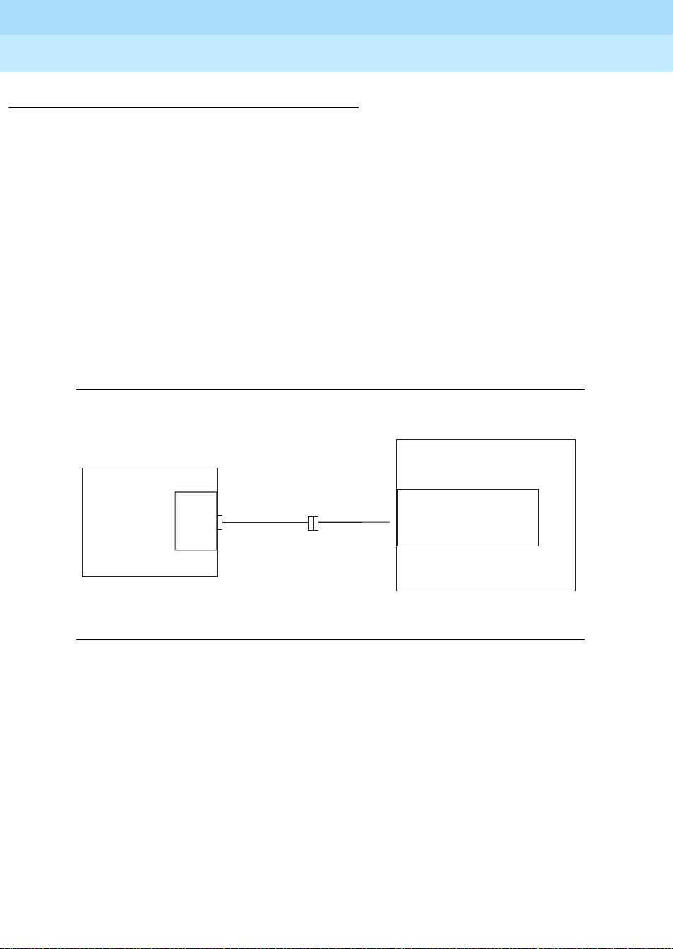
Cabling Diagram
555-231-743
November 2000
Issue 1
11Installing the Management Terminal
PC
COM
Port
9-pin to
25-pin
Cable
(optional)
M25A or
M25B
RS232
Cable
Figure 1. Direct PC Connection to the Switch
Switch
TERM (J3) (csi),
TERM or DOT (si), or
»
TERMINALACTIVE (r)
pc2serv.cdr
Page 28

GuestWorks and DEFINITY ECS Release 9
Technician Handbook for Hospitality Installations
Installing the System
Activating the Systems
See the appropriate installation document for information about activating the
switch and the INTUITY system:
555-231-743
November 2000
Issue 1
12Activating t he Systems
■ For CMC installations, see Chapter 1 of
Upgrades and Additions for Compact Modular Cabinets.
■ For SCC installations, see Chapter 3 of
Test for Single-Carrier Cabinets.
■ For MCC installations, see Chapter 3 of
Test for Multi-Carrier Cabinets.
■ For installations with an INTUITY system, see Chapter 4 in the INTUITY
installation documents.
Unless instructed otherwise,
always
translation card.
Setting Up the Initial Options
After activating the systems, there are some initial administration options you
must set up. In addition to the procedures given in this section, see the
appropriate installation document for information about setting up the initial
options:
■ For CMC installations, see Chapter 1 of
Upgrades and Additions for Compact Modular Cabinets.
■ For SCC installations, see Chapter 3 of
Test for Single-Carrier Cabinets.
DEFINITY ECS Installation,
DEFINITY ECS Installation and
DEFINITY ECS Installation and
activate your system using the default
DEFINITY ECS Installation,
DEFINITY ECS Installation and
■ For MCC installations, see Chapter 3 of
DEFINITY ECS Installation and
Test for Multi-Carrier Cabinets.
■ For installations with an INTUITY system, see Chapter 5 in the INTUITY
installation documents.
NOTE:
Before setting any options, ensure that the default translation card is being
used on a GuestWorks or DEFINITY BCS switch. A default translation card
is not used on a DEFINITY ECS or ProLogix switch.
Do the following to set up the initial options:
1. After the switch powers up, log on to the switch using the
craft
login ID
and the crftpw password. Distributors should use the dadmin login ID.
Page 29

GuestWorks and DEFINITY ECS Release 9
Technician Handbook for Hospitality Installations
Installing the System
2. Before you do any administration, verify that you are using the correct
translation card. For a DEFINITY ECS or ProLogix system, you will start
with a blank card, and all options must be set on site. For GuestWorks and
DEFINITY BCS, there is a default translation card that is already
administered for Offer Category B with certain default options. Check this
by using the display system-parameters offer-options command.
NOTE:
If the Offer Category is not set correctly and activated, contact
the technical support group or your regional Center of
Excellence (COE). The switch must be set to the correct Offer
Category; the translations must be saved; and the switch must
be reset before you can do any translations.
3. Set the required country options using the change system-parameters
country-options command.
4. Set the daylight savings time rules using the change daylight-savings-
rules command.
555-231-743
November 2000
Issue 1
13Setting Up the Initial Options
5. Set the date and the time using the set time command. This includes
applying the daylight savings time rules set up in Step 4.
6. If the switch has EPNs in different time zone locations, use the change
location command to set the time zone offset, daylight savings rules, and
numbering plan area code.
7. Set the switch maintenance parameters using the change system-
csi
parameters maintenance command. For
systems that have a C-LAN
(TN799C) circuit pack, use Page 2 of this screen to verify that the Bus
Bridge Packet Interface 2 has been enabled for the C-LAN circuit pack. If it
is not already assigned, enter the C-LAN circuit pack equipment location,
and use the defaults for the Timeslot Port fields as shown below.
change system-parameter maintenance Page 2 of 4
MINIMUM MAINTENANCE THRESHOLDS ( Before Notification )
TERMINATING TRUNK TRANSMISSION TEST (Extension)
ISDN MAINTENANCE
DS1 MAINTENANCE
SPE OPTIONAL BOARDS
TTRs: 4 CPTRs: 1 Call Classifier Ports:
MMIs: 0 VCs:
Test Type 100: Test Type 102: Test Type 105:
ISDN-PRI TEST CALL Extension: ISDN BRI Service SPID:
DSO Loop-Around Test Call Extension:
Bus Bridge: 03C05 Inter-Board Link Timeslots Pt0: 6 Pt1: 1 Pt2: 1
Packet Intf1? y Packet Intf2? y
MAINTENANCE-RELATED SYSTEM PARAMETERS
Page 30

GuestWorks and DEFINITY ECS Release 9
Technician Handbook for Hospitality Installations
Installing the System
8. Verify that the hospitality customer options have been enabled by checking
the display system-parameters customer-options screen. On Page 3,
the following options must be enabled:
■ Hospitality (Basic)
■ Hospitality (G3V3 Enhancements)
These options can be enabled only with the
support or your COE if you do not have permission to make this change.
9. Change the craft password using the change password craft command.
!
CAUTION:
After the craft password is changed, the new password must be
safeguarded to prevent unauthorized administration changes.
This password MUST NOT BE REVEALED to the customer.
10. Save these initial translations. Use the save translation command. Label
the translation card with the current date and switch name.
555-231-743
November 2000
init
login ID. Contact technical
Issue 1
14Setting Up the Initial Options
!
CAUTION:
It is recommended that you save your translations regularly
during the installation process. If a power failure occurs, all
translations since the last save are lost and must be
readministered.
Page 31

GuestWorks and DEFINITY ECS Release 9
Technician Handbook for Hospitality Installations
Installing the System
555-231-743
Connecting the Hospitality Adjuncts
The hospitality adjuncts include the following:
■ INTUITY Lodging Voice Messaging
INTUITY Lodging Voice Messaging is an optional adjunct that resides on
the MAP. INTUITY Lodging is used for the guest access to voice
messages; and INTUITY AUDIX is used for the office staff to access voice
messaging.
■ INTUITY Lodging Call Accounting
INTUITY Lodging Call Accounting is a co-resident application from
Homisco that resides on the MAP. It is based on a product from the
Homisco Corporation. At most installations, you can expect a technician
from Homisco to be on site to install the software and hardware for the call
accounting portion of the product. The Homisco technician will assist you in
making the call accounting system interface to the switch.
For installations that include INTUITY Lodging Voice Messaging and
INTUITY Lodging Call Accounting, all connections are shown in complete
detail.
November 2000
Issue 1
15Connecting the Hospita lity Adjuncts
■ Stand-Alone Call Accounting
Stand-alone call accounting systems (such as Xiox) can be installed if the
call record format is compatible with the switch. Two typical formats are
printer
and
Teleseer
.
For installations that include voice mail or call accounting from another
vendor, the connections are shown up to a definable demarcation point.
Connections beyond that demarcation point must be coordinated with the
vendor.
■ Property Management System (PMS)
The PMS is a vendor-provided product that interfaces to the switch
according to the
System Interface Specifications
GuestWorks and DEFINITY ECS Property Management
. If the PMS follows those specifications,
the PMS will interface to the switch when properly connected to the switch.
The PMS connections are shown up to a definable demarcation point.
Connections beyond that demarcation point must be coordinated with the
vendor.
Page 32

GuestWorks and DEFINITY ECS Release 9
Technician Handbook for Hospitality Installations
Installing the System
■ Printers
Two serial printers can be installed to print hospitality reports and to keep a
log of events as they occur on the switch. Each printer connects to the
switch using a DCP data module. The printers are designated as either a
“journal/schedule” printer or a “log” printer. The journal/schedule printer
records Emergency Access to Attendant calls and Automatic Wakeup calls.
The log printer records housekeeping updates when the PMS link is down,
in addition to recording any other PMS-related events. These PMS events
are shown in “Appendix C — List PMS Down Events” on page 245.
NOTE:
In most cases, only one printer is provided to perform both the
journal/schedule and log printer functions.
A parallel printer may be connected to the INTUITY system to run call
accounting reports or reports from the INTUITY messaging system.
555-231-743
November 2000
Issue 1
16Connecting the Hospita lity Adjuncts
Page 33

GuestWorks and DEFINITY ECS Release 9
Technician Handbook for Hospitality Installations
Installing the System
Overall Hospitality Connectivity
Figure 2 shows the overall connectivity for a hospitality installation when using the
MAP for INTUITY Lodging Voice Messaging, INTUITY Lodging Call Accounting,
plus connections to a PMS. References to the detailed connectivity drawings are
shown in this figure. Table 2 also gives references to the detailed connectivity
drawings based on the equipment you are installing.
555-231-743
November 2000
Issue 1
17Connecting the Hospita lity Adjuncts
For
INADS
Console
715
or PC
Optional
System or
Journal
Serial
Printer
For
INADS
X
C
O
N
Digital
Sets
Analog
Sets
Fig. 21
Fig. 1
Data
Module
Fig. 19
Modem
Fig. 22
X
C
O
N
X
C
O
N
X
C
O
N
X
C
O
N
Switch
Digital
Line
Digital
Line
Analog
Line
TERM
Digital
Line
AUX
(SCC or
MCC)
Modem
P2 (CMC)
TN799
C-LAN
TN765 (si)
TN577 (r)
Analog
Line
EIA DCE
(csi/si)
Digital
Line
Fig.3or4
Crossover
Cable or
Hub/Router
IDI
Fig. 6
X
C
885A
O
Kit
N
LAN
Card
DCIU
Card
T/R
Card
MAP
COM1
COM2
RMB
Fig. 9
Fig. 12
(See Fig. 13-15
for additional
CDR connectivity
options)
Fig. 16
Data
Module
Serial
Card
TTYsaa
Serial
Card
TTYsab
Call
Acctng
Port
Switch
Port
Printer
Port
Serial
Card
TTYsac
Voice
Msgng
Port
Fig. 20
Fig. 10*
PMS
* This link is not used with the Switch/Intuity/PMS
Link Integration feature. This link is required
when using Mode Code Integration.
Fig. 23
Comsphere
3820
Comsphere
3820
OR
Parallel
Printer
Front Desk
Terminal
Printer
For
Remote
Admin
(Optional)
For
INADS
For
INADS
gws_sol2.cdr
Figure 2. Overall Hospitality Connectivity
Page 34

GuestWorks and DEFINITY ECS Release 9
Technician Handbook for Hospitality Installations
Installing the System
Table 2. Matrix for Cabling Diagrams
555-231-743
To...
November 2000
Issue 1
18Connecting the Hospita lity Adjuncts
INTUITY
Switch
From...
Switch
INTUITY
Lodging
Voice
Messaging
INTUITY
Lodging
Call
Accounting
Xiox Call
Accounting
Stand-alone
Call
Accounting
* This connection is not required when using the Switch/INTUITY/Link Integration feature.
Figure 3,
Figure 4,
Figure 6,
or
Figure 9
Figure 1 2
or
Figure 1 5
Figure 1 3
or
Figure 1 5
Figure 1 4
or
Figure 1 5
Lodging
Voice
Messaging
Figure 3,
Figure 4,
Figure 6 , or
Figure 9
INTUITY
Voice
Ports
Figure 9 Figure12
INTUITY
Lodging
Call
Accounting
or
Figure 1 5
Xiox Call
Accounting
Figure 13
or
Figure 15
Stand-alone
Call
Accounting
Figure 1 4
or
Figure 1 5
PMS
Figure 18
Figure 10
or
Figure 11*
Figure 16
Figure 17
Designed
Locally
In Figure 2, there are a variety of digital line circuit packs and telephones/data
modules that can be used. Table 3 shows which circuit packs should be us ed to
support the different digital telephones and data modules.
Table 3. Digital Line Circuit Packs and Telephone Equipment Compatibility
Circuit Packs
TN754C
Equipment
302B Console (2-wire/4-wire) Yes Yes Yes Yes
302C Console (2-wire/4-wire) Yes Yes Yes Yes
6400-Series telephones (2-wire) No Yes Yes Yes
7400-Series telephones/data modules
(4-wire)
8400-Series telephones/data modules
(2-wire/4-wire)
(4-wire)
YesNoNoNo
Yes Yes Yes Yes
TN2181
(2-wire)
TN2214
(2-wire)
TN2224
(2-wire)
Page 35

GuestWorks and DEFINITY ECS Release 9
Technician Handbook for Hospitality Installations
Installing the System
Switch-to-INTUITY Admin Link (TCP/IP)
This data link transfers information to support the INTUITY AUDIX service for
office staff voice messaging. For all new installations, this is the recommended
way to connect the switch to the MAP for voice messaging administrative
messages. If the system is an upgrade, you may reuse the X.25 hardware for this
connection; see “Switch-to-INTUITY Admin Link (X.25)” on page 22. For
installations using Mode Code integration, see “Switch-to-INTUITY Admin Link
(Mode Code Integration)” on page 24.
Parts List
■ An ethernet port on the C-LAN circuit pack
■ One 259A adapter (comcode 102631413), or
UTP Category 5 cross-connect hardware and connecting blocks
■ One 6-inch RJ45 crossover cord (comcode 846943306 or 104154414), or
One 10/100Base-T auto-sensing LAN hub or customer router (optional)
555-231-743
November 2000
Issue 1
19Connecting the Hospita lity Adjuncts
■ One or two RJ45 UTP Category 5 modular cords (see “Appendix A —
■ One or more 451A in-line RJ45 adapters, as needed (used to connect
■ One LAN card on the MAP (for INTUITY R4.4, model 8412; for INTUITY
Distance Limits
Using the standard crossover cord (or alternate crossover wiring arrangement in
Figure 5), the distance limit between the switch and the MAP is 328 feet (100
meters).
Using a hub or customer router, the distance limit between the switch and the
MAP is 656 feet (200 meters) total [328 feet (100 meters) from the switch to the
hub or router, and 328 feet (100 meters) from the hub or router to the MAP]. If the
distance between the switch and the MAP is more than 656 feet (200 meters), you
can daisy-chain up to four separate hubs.
Parts List” on page 242)
modular cords together)
R5, model 8416).
NOTE:
If you do locate the switch more than 50 feet (15.2 meters) from the MAP
and are using the coresident INTUITY Lodging Call Accounting system on
the MAP, the call accounting link limit of 50 feet (15.2 meters) must be
taken into account. Figure 15 shows how the call accounting link can be
extended beyond that limit.
Page 36

GuestWorks and DEFINITY ECS Release 9
Technician Handbook for Hospitality Installations
Installing the System
Cabling Diagram
Figure 3 shows a detailed connection between the C-LAN circuit pack and the
LAN card on the MAP when using the default crossover cord.
259A Adapter,
356A Adapter (Jack #1), or
258B Adapter (Jack #1)
Switch
C-LAN
Cat 5
25-Pair
Cable
Cat 5
Cross-
Connect
Field
Crossover Cord
OR
Connecting
Cat 5
Wire
Cat 5
Block
555-231-743
Crossover
Cord
RJ45 Cat 5
Modular Cord
November 2000
Issue 1
20Connecting the Hospita lity Adjuncts
MAP
LAN
Card
328 ft max
(100 m)
Figure 3. Switch-to-INTUITY Admin Link (TCP/IP) with Crossover Cord
Figure 4 shows a detailed connection between the C-LAN circuit pack and the
LAN card on the MAP when using the optional hub or customer router.
259A Adapter,
356AAdapter (Jack #1), or
258B Adapter (Jack #1)
Switch
C-LAN
Cat 5
25-Pair
Cable
Cat 5
Cross-
Connect
Field
RJ45 Cat 5
Modular Cord
OR
Connecting
Cat 5
Wire
328 ft max
(100 m)
Cat 5
Block
RJ45 Cat 5
Modular Cord
Hub or
Router
AC Power
RJ45 Cat 5
Modular Cord
328 ft max
(100 m)
LAN
Card
lan_xover.cdr
MAP
lan_ded.cdr
Figure 4. Switch-to-INTUITY Admin Link (TCP/IP) with Hub or Router
Page 37

GuestWorks and DEFINITY ECS Release 9
RJ45
RJ45
6
5
4
3
6
5
4
3
RD-
RD+
TD-
TD+
RD-
RD+
TD-
TD+
104A Connecting
Block
Technician Handbook for Hospitality Installations
Installing the System
The C-LAN circuit pack ethernet lead designations are as follows:
555-231-743
November 2000
Issue 1
21Connecting the Hospita lity Adjuncts
Lead
Name
TD+ white/orange 27 1 3
TD- orange/white 2 2 4
RD+ white/green 28 3 5
RD- green/white 3 6 6
Use this information when making connections from the using a 259A adapter
(single-port), a 356A adapter (8-port harmonica), a 258B adapter (6-port
harmonica), or standard cross-connect wiring. When using the 356A or 258B
adapters, you must always connect to jack #1 of the adapter.
Crossover Wiring
If the standard crossover cord or the optional hub/router are not available, you can
build your own crossover wiring arrangement to flip the transmit and receive leads
for the LAN connection. Figure 5 shows how this can be done with a 104A
connecting block (comcode 105164859). When using this device, the distance
limit from the switch to the INTUITY system is 328 feet (100 meters). Using this
device, you would connect one Category 5 modular cord to the switch C-LAN
circuit pack, and another Category 5 modular cord to the INTUITY LAN card.
25-Pair Cable
Wire Color
25-Pair
Cable
Connector
Pin-out
RJ45
Jack
Pin-out
Terminal Block
Pin-out on
Connec ting Block
Figure 5. Alternate Crossover Wiring
Page 38

GuestWorks and DEFINITY ECS Release 9
Technician Handbook for Hospitality Installations
Installing the System
Switch-to-INTUITY Admin Link (X.25)
This data link transfers information to support the INTUITY AUDIX service for
office staff voice messaging. This connection will be used only if:
■ Your system has been upgraded from an earlier system, and
■ The customer chooses to retain their X.25 hardware (a PI circuit pack is
si
needed on the
r
system) instead of the TCP/IP C-LAN hardware.
See “Switch-to-INTUITY Admin Link (TCP/IP)” on page 19. For installations using
Mode Code integration, see “Switch-to-INTUITY Admin Link (Mode Code
Integration)” on page 24.
NOTE:
The connectivity shown in this section will not work on an
duplication. For a duplicated system, the connection between the switch
and the INTUITY is done with DCP data modules. See your project
manager for more information.
system, or a Packet Gateway circuit pack is needed on an
555-231-743
November 2000
si
system with
Issue 1
22Connecting the Hospita lity Adjuncts
Parts List
■ A PI port (TN765) on an
r
system
an
■ One H600-347 cable (
■ One H600-210 Group 3 cable (50 feet; 15.2 meters)
■ One 105C IDI (comcode 107422735) or 105D IDI (comcode 108367376)
si
system, or a Packet Gateway port (TN577) on
r
system only)
An IDI provides electrical isolation and protection between the switch and
the INTUITY hardware. The dip switch settings on the IDI must be set for
“Direct Connect.”
■ One ED1E434-11 Group 175 cable (4.5 feet; 1.5 meters)
■ One DCIU card (comcode 406801647, J1P260AA, L31) installed in the
MAP, usually located in slot 1.
Page 39

GuestWorks and DEFINITY ECS Release 9
Technician Handbook for Hospitality Installations
Installing the System
Distance Limits
The distance limit between the switch and the IDI is 200 feet (61 meters). If you
need a cable longer than the default 50 foot (15.2 meter) cable provided, order a
Group 4 cable (100 feet; 30.5 meters) or a Group 5 cable (200 feet; 61 meters).
See “Appendix A — Parts List” on page 242 for a list of cables.
NOTE:
If you locate the switch more than 50 feet (15.2 meters) from the MAP and
are using the coresident INTUITY Lodging Call Accounting system on the
MAP, the call accounting link limit of 50 feet (15.2 meters) must be taken
into account. Figure 15 shows how the call accounting link can be extended
beyond this limit.
Cabling Diagram
Figure 6 shows a detailed connection between a Processor Interface (PI) switch
si
port (
card on the MAP.
system) or Packet Gatew ay (P GATE) switch port (r system) and the DCIU
555-231-743
November 2000
Issue 1
23Connecting the Hospita lity Adjuncts
Switch
TN765
PI
Or
TN577
PGATE
«
H600-347
Cable
H600-210
Group 3
Cable
«
«
«
«
«
50 Ft.
«
In
(J1)
IDI
ED1E434-11
«
Out
(J2)
Figure 6. Switch-to-INTUITY Admin Link (X.25)
Group 175
Cable
MAP
DCIU
«
Card
pi2gp.cdr
Page 40

GuestWorks and DEFINITY ECS Release 9
Technician Handbook for Hospitality Installations
Installing the System
555-231-743
Switch-to-INTUITY Admin Link (Mode Code Integration)
When using Mode Code Integration, the administrative link between the switch
and the MAP (the link that transfers information to support the INTUITY AUDIX
service for office staff voice messaging) connects by way of an analog port on the
switch and a voice port on the MAP. This connection is the same as the voice port
connections shown in “Switch-to-INTUITY Voice Port Connections” on page 25
and in Figure 9.
In other words, the voice ports used for leaving and retrieving messages on the
INTUITY system are the same voice ports used for Mode Code Integration. This
means that the ports will be in use for the amount of time it takes to leave a
message, plus the amount of time it takes for the Mode Codes to exchange
messages between the switch and INTUITY. This will affect the traffic-handling of
the voice messaging system.
Mode Code Integration should not be used if TCP/IP or X.25 link integration is
available. See “Switch-to-INTUITY Admin Link (TCP/IP)” on page 19 or “Switch-
to-INTUITY Admin Link (X.25)” on page 22 for more information.
November 2000
Issue 1
24Connecting the Hospita lity Adjuncts
NOTE:
When using Mode Code Integration, you cannot take advantage of the
Switch/INTUITY/PMS Link Integration feature. This means that you must
install the link shown in “INTUITY Lodging-to-PMS Link” on page 30.
Mode Code Integration between the switch and the MAP is described in more
detail in the following documents:
■
DEFINITY ECS Administrator’s Guide
■
INTUITY Messaging Solutions Release 4 MAP/5P System Installation
■
INTUITY Messaging Solutions Integration with System 75, DEFINITY
Generics 1 & 3, and R5/6
■
INTUITY Messaging Solutions Release 5 Documentation (CD).
Page 41

GuestWorks and DEFINITY ECS Release 9
Technician Handbook for Hospitality Installations
Installing the System
Switch-to-INTUITY Voice Port Connections
This connection is used for the following:
■ For callers leaving messages for guests and office staff
■ For guests and office staff to call the INTUITY system to retrieve their voice
messages
■ For the administrative link between the switch and the MAP when using
Mode Code Integration (see page 24).
Parts List
■ One or more Tip/Ring cards in the MAP (different cards are required within
different regions of the world)
— IVC6 (AYC-10) Analog Voice Card (comcode 106406580)
— IVC6A (AYC-29) Tip/Ring Card (comcode 107213944)
— NGTR (AYC-30) Next Generation Tip/Ring Card
(comcode 107224586)
555-231-743
November 2000
Issue 1
25Connecting the Hospita lity Adjuncts
Each Tip/Ring card supports six voice ports. For R5, you can have up to
three Tip/Ring cards to support 18 ports for voice messaging. For R4.4,
when using the Multi-Port Serial Card, you can have up to two Tip/Ring
cards to support 12 ports for voice messaging; when not using the
Multi-Port Serial Card, you can have up to three Tip/Ring cards to
support 18 ports for voice messaging.
If your system came from the factory configured with more than one tip/ring
card, the option settings on the cards should be set correctly. However, if
you are adding a card on-site, or if you want to check the card
configuration, Figure 7 shows the switch settings for the IVC6 (AYC-10)
and IVC6A (AYC-29) cards, and Figure 8 shows the switch settings for the
NGTR (AYC-30) card.
For each voice port card, you must install an 885A connector kit. Figure 9
shows connections for one kit using all six voice ports. Depending on the
customer’s order, you will install voice ports in pairs up to 18 ports.
■ Two or more ED5P208-30 Group 16 modular cords
You need two cords for each Tip/Ring card.
Page 42

GuestWorks and DEFINITY ECS Release 9
Technician Handbook for Hospitality Installations
Installing the System
■ One 885A connector kit for each Tip/Ring card installed in the MAP
(ED-5P907-70, Group 1, comcode 601419666)
These kits come with one 885A connecting block, six RJ11C 4-wire
modular cords (comcode 103732582), and two RJ25 6-wire modular cords.
!
CAUTION:
The two RJ25 6-wire modular cords that come with the 885A
connector kits are not used in this application. Do not use the
RJ25 cords for any connections; the wiring in the RJ25 cords will
not work in this application.
Use the 885A connecting block label to record the extension numbers of
the voice ports connected to the MAP.
■ Ferrites (one for each voice line) (comcode 407616846)
555-231-743
November 2000
Issue 1
26Connecting the Hospita lity Adjuncts
■ 103A modular connecting blocks (one for each voice port)
■ Standard cross-connect hardware
■ Ports on an analog circuit pack.
Distance Limits
The distance limit from an analog port to the MAP is 20000 feet (6100 meters)
using 24 AWG wire.
Ferrites are required for installation in some countries. See
Messaging Solution Release 4 Supplement for Technicians
INTUITY
for more
information.
(comcode 105164818)
Each analog circuit pack supports 8, 16, or 24 analog voice connections.
Depending on the circuit pack and the required number of voice ports, you
may need to spread out the voice port assignments over more than one
circuit pack. For example, if you are using a 16-port circuit pack, use no
more than four ports of circuits 1-8 and four ports of circuits 9-16 on that
circuit pack. If you still need more INTUITY voice ports, select a circuit pack
that is at least one-quarter carrier distance away from the first circuit pack.
For example, if your system has 12 voice ports, and you assign the first
eight ports to the circuit pack in slot 3, assign the other four voice ports to a
circuit pack in slot 7 or higher. See more about circuit pack characteristics
DEFINITY ECS System Description
in the
.
Page 43

GuestWorks and DEFINITY ECS Release 9
Technician Handbook for Hospitality Installations
Installing the System
Base I/O address = 100 Hex.
Base I/O address = 200 Hex.
Base I/O address = 300 Hex.
555-231-743
Rocker
switches
(see IVC6
switch setting
figure)
TDM bus
terminator SIPs
November 2000
Issue 1
27Connecting the Hospita lity Adjuncts
8-pin
modular
jacks
Audio
input
Audio
output
IVC6 T/R 0
First card installed
Base I/O address = 500 Hex.
IVC6 T/R 3
Fourth card installed
Base I/O address = 900 Hex.
IVC6 T/R 6
Seventh card installed
IVC6 T/R 1
Second card installed
Base I/O address = 600 Hex.
IVC6 T/R 4
Fifth card installed
Note:
Rocker switches5 and 6 can be
set either open or closed.
IVC6 T/R 2
Third card installed
Base I/O address = 700 Hex.
IVC6 T/R 5
Sixth card installed
Figure 7. IVC6 and IVC6A Tip/Ring Card Switch Settings
Page 44

GuestWorks and DEFINITY ECS Release 9
Technician Handbook for Hospitality Installations
Installing the System
555-231-743
I/O address switch
TDM bus B
November 2000
Issue 1
28Connecting the Hospita lity Adjuncts
TDM bus terminator SIPs
TDM bus A
8-pin
modular
jacks
Audio
input
Audio
output
ngtr KLC 070296
Figure 8. NGTR Tip/Ring Card Switch Settings
Page 45

GuestWorks and DEFINITY ECS Release 9
Technician Handbook for Hospitality Installations
Installing the System
Cabling Diagram
Figure 9 shows the connections between analog circuit pack ports on the switch
and a Tip/Ring card on the MAP.
MAP
Tip/Ring
Card
123
456
IN
AUDIO
OUT
ED5P208-30
Group 16
Modular Cords
LINES
1-2-3
LINES
4-5-6
RJ11C
4-Wire
Modular
Cords
LINE 1
LINE 2 LINE 3
EXT: EXT: EXT:
885AADAPTER
IVP6#
LINE 5
LINE 4
EXT:
EXT:
LINE 6
EXT:
103A
Connecting
Blocks
555-231-743
Cross-Connect
Field
November 2000
Issue 1
29Connecting the Hospita lity Adjuncts
Switch
Analog
Line
Figure 9. Switch-to-INTUITY Voice Port Connections
m5_791.cdr
Page 46

GuestWorks and DEFINITY ECS Release 9
Technician Handbook for Hospitality Installations
Installing the System
INTUITY Lodging-to-PMS Link
This connection is used to activate and deactivate guest voice messaging
mailboxes when guests check-in and check-out.
NOTE:
If the Switch/INTUITY/PMS Link Integration feature is used, this connection
is not required. See “INTUITY Lodging-to-PMS Translations” on page 195
for more information about this feature. If Mode Code Integration is used,
this link is required and cannot be removed.
Parts List
■ One Multi-Port Serial card on the MAP (comcode 407009406; J1P260AA1,
List 12)
For this connection, use the third port on the card. This port is not marked
on the card, but is administered in software as port TTYsac.
■ One D6AP modular cord (comcode 102937604)
555-231-743
November 2000
Issue 1
30Connecting the Hospita lity Adjuncts
■ One Equinox P/N:210068 DTE 10/10 adapter (DB25 DTE,
■ One null modem with transmit/receive swapped (all other leads are
■ One RS232 cable (use gender changers as needed).
Distance Limits
The distance limit from the MAP to the PMS is 50 feet (15.2 meters).
comcode 406983155); see “Appendix B — Connector Pinouts”
straight-through) (comcode 407122043)
Page 47

GuestWorks and DEFINITY ECS Release 9
Technician Handbook for Hospitality Installations
Installing the System
Cabling Diagram
Figure 10 shows the connection used for controlling guest mailboxes between the
MAP and the PMS. Use this connection when the MAP has a Multi-Port Serial
Card.
MAP
Modular
TTYsac
.
D6AP
Cord
555-231-743
RS232 25-pin
Null Modem
T/R Swap Only
Demarcation
RS232
Cable
November 2000
Issue 1
31Connecting the Hospita lity Adjuncts
Point
PMS
Voice
Messaging
Port
Multi-Port
Serial Card
Equinox
P/N:210068
DTE 10/10
Adapter
50 Ft. Maximum
Figure 10. INTUITY Lodging-to-PMS Link (Multi-Port Serial Card)
m5_pms2.cdr
Page 48

GuestWorks and DEFINITY ECS Release 9
Technician Handbook for Hospitality Installations
Installing the System
For some installations, the connection used for controlling guest mailboxes
between the MAP and the PMS uses COM1 instead of the Multi-Port Serial Card.
Figure 11 shows this connection.
MAP
.
RS232 25-pin
Null Modem
T/R Swap Only
555-231-743
November 2000
Issue 1
32Connecting the Hospita lity Adjuncts
Demarcation
Point
PMS
RS232
Cable
COM1
50 Ft. Maximum
Figure 11. INTUITY Lodging-to-PMS Link (COM1)
Voice
Messaging
Port
map_pms_com1.cdr
Page 49

GuestWorks and DEFINITY ECS Release 9
Technician Handbook for Hospitality Installations
Installing the System
Test Procedure
Using the RS232 Mini-T ester (see the Note on page 5), check th e statu s of the link
where the Equinox adapter connects to the null modem as shown in Figure 10.
The leads marked with an asterisk are controlled by the INTUITY system, and the
PMS controls the other leads. Translations for this connection begin on page 195.
!
CAUTION:
After using a mini-tester to check data leads, you MUST remove the
mini-tester from the connection. DO NOT leave the mini-tester in-line during
actual operation.
With the mini-tester connected to only the Equinox adapter coming from the MAP ,
the mini-tester should show the following:
555-231-743
November 2000
Issue 1
33Connecting the Hospita lity Adjuncts
TD*
RTS*
DSR
CD
red
dark
dark
dark
dark
dark
green
RD
CTS
DTR*
With the mini-tester connected to only the PMS at the null modem, the mini-tester
should show the following:
TD*
RTS*
DSR
CD
dark
dark
red
red
red
red
dark
RD
CTS
DTR*
With the mini-tester connected to the MAP and the PMS, but in an idle state, the
mini-tester should show the following:
TD*
RTS*
DSR
CD
red
dark
red
red
red
red
green
RD
CTS
DTR*
Page 50

GuestWorks and DEFINITY ECS Release 9
Technician Handbook for Hospitality Installations
Installing the System
Switch-to-Call Accounting Links
The switch-to-call accounting link can be configured several different ways
depending on the ports used at the switch and the type of call accounting system.
This section describes the following call accounting configurations:
■ Co-resident INTUITY Lodging call accounting system (Homisco) using the
DCE port
■ Xiox call accounting sys tem usi ng the DCE port
■ Stand-alone call accouting system using the DCE port
■ Call accounting link using DCP data modules.
555-231-743
November 2000
Issue 1
34Connecting the Hospita lity Adjuncts
Page 51

GuestWorks and DEFINITY ECS Release 9
Technician Handbook for Hospitality Installations
Installing the System
555-231-743
Co-Resident INTUITY Lodging Call Accounting Link Using the DCE Port
This connection is used to transfer Call Detail Recording (CDR) information to the
co-resident INTUITY Lodging Call Accounting software (Homisco). This
csi
connection is valid for a
or si system.
Parts List
■ The DCE port on the switch (this port is found on the Processor Interface
csi
Cable of a
■ One M25A RS232 cable (or equivalent straight-through cable)
(comcode 105193668)
■ One Equinox P/N:210068 DTE 10/10 adapter (DB25 DTE,
comcode 406983155); see “Appendix B — Connector Pinouts”
■ One D6AP modular cord (comcode 102937604)
■ One Multi-Port Serial card on the MAP (comcode 407009406; J1P260AA1,
List 12).
system labeled as J2)
November 2000
Issue 1
35Connecting the Hospita lity Adjuncts
For this connection, use the first port on the card. This port is not marked
on the card, but is administered in software as port TTYsaa.
Distance Limits
The distance limit from the switch to the MAP is 50 feet (15.2 meters). If the
distance from the switch and the MAP is more than 50 feet (15.2 meters), or if the
r
switch is an
Modules” on page 46.
system, see “Switch-to-Call Accounting Link using DCP Data
Page 52

GuestWorks and DEFINITY ECS Release 9
Technician Handbook for Hospitality Installations
Installing the System
Cabling Diagram
Figure 12 shows the connection used to transfer CDR information between the
csi
DCE port on a
Switch
DCE (J2) (csi)
or si system and the MAP .
M25A
RS232
DCE (si)
«
Cable
555-231-743
D6AP
Modular
Cord
«
November 2000
Issue 1
36Connecting the Hospita lity Adjuncts
MAP
TTYsaa
Equinox
P/N:210068
DTE 10/10
Adapter
50 Ft. Maximum
Multi-Port
Serial Card
eia2map.cdr
Figure 12. Co-Resident INTUITY Lodging Call Accounting Link Using the
DCE Port
Page 53

GuestWorks and DEFINITY ECS Release 9
Technician Handbook for Hospitality Installations
Installing the System
Test Procedure
Using the RS232 Mini-T ester (see the Note on page 5), check th e statu s of the link
where the Equinox adapter connects to the M25A cable as shown in Figure 12.
The leads marked with an asterisk are controlled by the switch, and the INTUITY
Lodging Call Accounting system controls the other leads. Translations for this
begin on page 205.
!
CAUTION:
After using a mini-tester to check data leads, you MUST remove the
mini-tester from the connection. DO NOT leave the mini-tester in-line during
actual operation.
With the mini-tester connected to only the M25A cable, the mini-tester should
show the following:
TD
dark
RD*
CTS*
DTR
RTS
DSR*
CD*
red
dark
green
green
dark
green
555-231-743
November 2000
Issue 1
37Connecting the Hospita lity Adjuncts
With the mini-tester connected to only the Equinox adapter, the mini-tester should
show the following:
red
TD
RTS
DSR*
CD*
dark
dark
dark
dark
green
red
RD*
CTS*
DTR
Page 54

GuestWorks and DEFINITY ECS Release 9
Technician Handbook for Hospitality Installations
Installing the System
With the mini-tester connected to the M25A cable and the Equinox adapter, the
mini-tester should show the following (if any of the switch leads are dark on an
end-to-end connection, the processor circuit pack should be replaced):
555-231-743
November 2000
Issue 1
38Connecting the Hospita lity Adjuncts
TD
RTS
DSR*
CD*
red
dark
green
green
red
green
green
RD*
CTS*
DTR
Another way to test this connection is to connect a dumb terminal to the DCE port
on the switch, make some test calls, and look for call records being displayed on
the terminal.
Page 55

GuestWorks and DEFINITY ECS Release 9
Technician Handbook for Hospitality Installations
Installing the System
Xiox Call Accounting System Link Using the DCE Port
This connection is used to transfer CDR information to the Xiox call accounting
system. This connection is valid for a
Parts List
■ The DCE port on the switch (this port is found on the Processor Interface
csi
Cable of a
■ One M25A or M25B cable plus gender changers as needed (or
system labeled as J2)
equivalent 25-pin straight-through cable) to connect from the DCE port to
the PBX port on the Xiox Intelligent Buffer unit
■ Xiox Intelligent Buffer unit (includes AC power adapter and cable for
connection to the Xiox call accounting PC)
■ Xiox call accounting PC.
Distance Limits
The distance limit from the switch to the Xiox call accounting PC is 50 feet (15.2
meters). If the distance from the switch and the PC is more than 50 feet (15.2
r
meters), or if the switch is an
DCP Data Modules” on page 46.
system, see “Switch-to-Call Accounting Link using
555-231-743
csi
or si system.
November 2000
Issue 1
39Connecting the Hospita lity Adjuncts
Page 56

GuestWorks and DEFINITY ECS Release 9
Technician Handbook for Hospitality Installations
Installing the System
Cabling Diagram
555-231-743
November 2000
Issue 1
40Connecting the Hospita lity Adjuncts
Figure 13 shows the connection between the DCE port on a
csi
or si system and a
Xiox call accounting system.
Switch
DCE (si)
DCE (J2) (csi)
«
Demarcation
M25A or
M25B RS232
Cable
Point
Xiox Intelligent
Buffer
PBX
50 Ft. Maximum
PC
Xiox Call
Accounting PC
COM1
RS232
Cable
xiox_ca.cdr
Figure 13. Xiox Call Accounting System Link Using the DCE Port
Page 57

GuestWorks and DEFINITY ECS Release 9
Technician Handbook for Hospitality Installations
Installing the System
Test Procedure
Using the RS232 Mini-T ester (see the Note on page 5), check th e statu s of the link
at the point where the M25 cable connects to the Xiox Intelligent Buffer as shown
in Figure 13. The leads marked with an asterisk are controlled by the switch, and
the call accounting system controls the other leads. Translations for this
connection begin on page 205.
!
CAUTION:
After using a mini-tester to check data leads, you MUST remove the
mini-tester from the connection. DO NOT leave the mini-tester in-line during
actual operation.
With the mini-tester connected to only the M25 cable from the switch, the minitester should show the following:
dark
TD
RD*
CTS*
DTR
RTS
DSR*
CD*
dark
red
green
green
dark
green
555-231-743
November 2000
Issue 1
41Connecting the Hospita lity Adjuncts
With the mini-tester connected to only the PBX port on the Xiox Intelligent Buffer,
the mini-tester should show the following:
red
TD
RTS
DSR*
CD*
dark
green
dark
dark
green
dark
RD*
CTS*
DTR
Page 58

GuestWorks and DEFINITY ECS Release 9
Technician Handbook for Hospitality Installations
Installing the System
With the mini-tester connected to the switch and the PBX port on the Xiox
Intelligent Buffer, the mini-tester should show the following (if any of the switch
leads are dark in an end-to-end connection, the processor circuit pack should be
replaced):
red
TD
RD*
CTS*
DTR
RTS
DSR*
CD*
green
red
green
green
green
green
Another way to test this connection is to connect a dumb terminal to the DCE port
on the switch, make some test calls, and look for call records being displayed on
the terminal.
555-231-743
November 2000
Issue 1
42Connecting the Hospita lity Adjuncts
Page 59

GuestWorks and DEFINITY ECS Release 9
Technician Handbook for Hospitality Installations
Installing the System
Stand-alone Call Accounting System Link Using the DCE Port
This connection is used to transfer CDR information to a stand-alone call
accounting system. This connection is valid for a
Parts List
■ The DCE port on the switch (this port is found on the Processor Interface
csi
Cable of a
■ One M25A or M25B cable plus gender changers as needed (or
system labeled as J2)
equivalent 25-pin straight-through cable) to connect from the DCE port to
the interface port on the call accounting system.
Distance Limits
The distance limit from the switch to the stand-alone call accounting system is 50
feet (15.2 meters). If the distance from the switch and the call accounting system
is more than 50 feet (15.2 meters), or if the switch is an
Call Accounting Link using DCP Data Modules” on page 46.
555-231-743
csi
or si system.
r
system, see “Switch-to-
November 2000
Issue 1
43Connecting the Hospita lity Adjuncts
Cabling Diagram
Figure 14 shows the connection between the DCE port on a
stand-alone call accounting system.
Switch
M25A or M25B
DCE (si)
DCE (J2) (csi)
«
RS232 Cable
Accounting
Demarcation
Point
50 Ft. Maximum
Figure 14. Switch-to-Call Accounting Link (Stand-Alone Call Accounting
System)
csi
or si system and a
Standalone
Call Accounting
Call
Port
eia2gca.cdr
Page 60

GuestWorks and DEFINITY ECS Release 9
Technician Handbook for Hospitality Installations
Installing the System
Test Procedure
Using the RS232 Mini-T ester (see the Note on page 5), check th e statu s of the link
at the demarcation point as shown in Figure 14. The leads marked with an
asterisk are controlled by the switch, and the call accounting system controls the
other leads. Translations for this connection begin on page 205.
!
CAUTION:
After using a mini-tester to check data leads, you MUST remove the
mini-tester from the connection. DO NOT leave the mini-tester in-line during
actual operation.
With the mini-tester connected to only the M25 cable from the switch, the minitester should show the following:
dark
TD
RD*
CTS*
DTR
RTS
DSR*
CD*
dark
red
green
green
dark
green
555-231-743
November 2000
Issue 1
44Connecting the Hospita lity Adjuncts
With the mini-tester connected to only the interface port on the stand-alone call
accounting system, the mini-tester should show the following:
red
TD
RTS
DSR*
CD*
dark
green
dark
dark
green
dark
RD*
CTS*
DTR
Page 61

GuestWorks and DEFINITY ECS Release 9
Technician Handbook for Hospitality Installations
Installing the System
With the mini-tester connected to the switch and the stand-alone call accounting
system, the mini-tester should show the following (if any of the switch leads are
dark in an end-to-end connection, the processor circuit pack should be replaced):
red
TD
RD*
CTS*
DTR
RTS
DSR*
CD*
green
red
green
green
green
green
Another way to test this connection is to connect a dumb terminal to the DCE port
on the switch, make some test calls, and look for call records being displayed on
the terminal.
555-231-743
November 2000
Issue 1
45Connecting the Hospita lity Adjuncts
Page 62

GuestWorks and DEFINITY ECS Release 9
Technician Handbook for Hospitality Installations
Installing the System
Switch-to-Call Accounting Link using DCP Data Modules
This connection is used when the distance between the switch and the call
accounting system is greater than 50 feet (15.2 meters), or when using an
system.
Parts List
Co-Resident INTUITY Lodging Call Accounting (Homisco)
■ One digital communications protocol (DCP) port on the switch; the 8400B
data module uses a TN2214 or TN2224 2-wire digital port, and the 7400A
and 7400B data modules use a TN754C 4-wire digital port
■ Standard cross-connect hardware
■ One D8W modular cord
■ One 8400B data module optioned as shown on page 48, a 7400A data
module optioned as shown in Table 4, or a 7400B data module optioned as
shown on page 50
555-231-743
November 2000
Issue 1
46Connecting the Hospita lity Adjuncts
r
■ One DB9-to-DB25 transition cable when using the 8400B data module
■ One Equinox P/N:210068 DTE 10/10 adapter (DB25 DTE,
comcode 406983155); see “Appendix B — Connector Pinouts”
■ One D6AP modular cord (comcode 102937604).
Xiox or other stand-alone call accounting system
■ One digital communications protocol (DCP) port on the switch; the 8400B
data module uses a TN2214 or TN2224 2-wire digital port, and the 7400A
and 7400B data modules use a TN754C 4-wire digital port
■ Standard cross-connect hardware
■ One D8W modular cord
■ One 8400B data module optioned as shown on page 48, a 7400A data
module optioned as shown in T able 4 on Page 49, or a 7400B data module
optioned as shown on page 50
■ One DB9-to-DB25 transition cable when using the 8400B data module
■ One M25A or M25B cable (or equivalent 25-pin straight-through cable);
see “Appendix A — Parts List” on page 242.
Page 63

GuestWorks and DEFINITY ECS Release 9
Technician Handbook for Hospitality Installations
Installing the System
Distance Limits
The distance limit when connecting a data module to a TN2214 or TN2224 with 24
AWG wire is 3500 feet (1067 meters). The distance limit when connecting a data
module to a TN754C is 5000 feet (1524 meters) with 24 AWG wire, and 4000 feet
(1219 meters) with 26 AWG wire.
Cabling Diagram
Figure 15 shows the connection between the switch and the call accounting
system (INTUITY Lodging Call Accounting or stand-alone call accounting) when
using a DCP data module. Use these connections for
555-231-743
r
systems.
November 2000
Issue 1
47Connecting the Hospita lity Adjuncts
Switch
Digital
Port
Cross-Connect
Field
103A
Connecting
Block
3500-5000 Ft. Maximum
D8W
Modular
Cord
Data
Module
AC Power
Demarcation
«
M25A or
M25B RS232
Cable
«
Point
Xiox Intelligent
Buffer
PBX
OR
M25A or M25B
RS232 Cable
OR
D6AP
Modular
Cord
PC
RS232
Cable
Accounting
Demarcation
Point
Call Accounting)
Xiox Call
Accounting PC
COM1
Standalone
Call Accounting
Call
Port
MAP
(Intuity Lodging
TTYsaa
Equinox
P/N:210068
DTE 10/10
eia2datamod.cdr
Adapter
50 Ft. Maximum
Figure 15. Call Accounting Link using DCP Data Modules
Multi-Port
Serial Card
Page 64

GuestWorks and DEFINITY ECS Release 9
Enter
Enter
Technician Handbook for Hospitality Installations
Installing the System
8400B Options
The options on the 8400B must be set using an ASCII data terminal or a PC using
a terminal emulation package. You must connect the data terminal or PC to the
EIA interface connector on the back of the 8400B. For the switch-to-call
accounting link, a subset of options must be changed. These options are changed
using the AT command set. Use the following steps to set the options on
the 8400B:
1. Set the speed on the data terminal or terminal emulation package to match
the speed of the call accounting system. By doing this, the speed on
the 8400B will autobaud to match the correct speed.
555-231-743
November 2000
Issue 1
48Connecting the Hospita lity Adjuncts
2. From the data terminal or PC, type at . This automatically sets the
Enter
speed and parity for the connection. The OK prompt should display.
3. Type the following commands as shown. (The character 0 is the number
zero.) Before you press for each command, make sure that the
Enter
command has been entered correctly. The e0 option on the last command
turns off keyboard echo, which means that after you enter this command,
any future keyboard entries will not be displayed, and the OK prompt is not
displayed.
Enter
at&f (the OK prompt displays)
ats24=1 (the OK prompt displays)
Enter
at&c1&d2&s1s0=1 (the OK prompt displays)
ate0q1&w0&y0&v
The &v portion of the last command displays the current set of options.
Your screen should look something like this:
ACTIVE PROFILE:
B1 E0 L2 M1 Q1 V1 X4 Y0 &C1 &D2 &G0 &J0 &L0 &P0 & Q0 &R0 &S1 &X0 &Y0
S00:001 S01:000 S02:043 S03:013 S04:010 S05:008 S06:002 S07:060
S08:002 S09:006 S10:014 S12:050 S14:ACH S16:00H S18:000 S21:70H
S22:76H S23:1BH S24:01H S25:005 S26:001 S27:40H
STORED PROFILE 0:
B1 E0 L2 M1 Q1 V1 X4 Y0 &C1 &D2 &G0 &J0 &L0 &P0 &Q0 &R0 &S1 &X0
S00:001 S14:ACH S18:000 S21:70H S22:76H S23:1BH S24:01H S25:005
S26:001 S27:40H
STORED PROFILE 1:
B1 E1 L2 M1 Q0 V1 X4 Y0 &C0 &D0 &G0 &J0 &L0 &P0 &Q0 &R0 &S0 &X0
S00:000 S14:AAH S18:000 S21:00H S22:76H S23:1BH S24:01H S25:005
S26:001 S27:40H
TELEPHONE NUMBERS:
4. Disconnect the data terminal or PC from the 8400B.
5. Reconnect the unit as shown in Figure 15.
6. Cycle power on the 8400B (disconnect the line cord momentarily).
Page 65

GuestWorks and DEFINITY ECS Release 9
Technician Handbook for Hospitality Installations
Installing the System
If your call accounting system requires a different set of options, consult
8400B Plus Data Module User’s Guide
the
7400A Options
The options for the 7400A used for the switch-to-call accounting connection are
given in Table 4. These options must match the call accounting system
communication parameters, which are usually 9600 bps, 8 data bits, 1 stop bit,
and no parity.
The data module interface board must be positioned at the DCE location, and the
interface option must be set for Answer-Only mode.
Table 4. 7400A Options for Switch-to-Call Accounting Link
Set Interface Set Values
Option Answer-only mode
Set Option Displays Set Values
*Set 300 speed OFF
*Set 1200 speed OFF
*Set 2400 speed OFF
*Set 4800 speed OFF
*Set 9600 speed ON
*Set 19200 speed OFF
Set Answer AUTO
Set Break DISC LONG
Set CI Lead OFF
Set CH Lead OFF
Set CTS Lead NORMAL
Set DCD Lead NORMAL
Set DSR Lead NORMAL
Set DTR Detect 50
Set DTR Lead FOLLOW
Set LL Lead OFF
Set Remote Loop GRANT
Set RI Lead ON
Set RL Lead OFF
Set SIGLS DISC ON
Set TM Lead OFF
* Verify the speed setting with the call accounting vendor.
Enable other speeds as needed.
555-231-743
.
November 2000
Issue 1
49Connecting the Hospita lity Adjuncts
Page 66

GuestWorks and DEFINITY ECS Release 9
Enter
Enter
Technician Handbook for Hospitality Installations
Installing the System
7400B Options
The options on the 7400B must be set using an ASCII data terminal or a PC using
a terminal emulation package. You must connect the data terminal or PC to the
EIA interface connector on the back of the 7400B. For the switch-to-call
accounting link, only a subset of options must be changed. These options are
changed using the AT command set. Use the following steps to set the options on
the 7400B:
1. Set the option dip switches SW1-1 to ON (without phone), SW1-5 to OFF,
and SW1-8 to OFF.
2. Set the speed on the data terminal or terminal emulation package to match
the speed of the call accounting system. By doing this, the speed on
the 7400B will autobaud to match the correct speed.
555-231-743
November 2000
Issue 1
50Connecting the Hospita lity Adjuncts
3. From the data terminal or PC, type at . This automatically sets the
Enter
speed and parity for the connection. The OK prompt should display.
4. Type the following commands as shown. (The character 0 is the number
zero.) Before you press for each command, make sure that the
Enter
command has been entered correctly. The e0 option on the last command
turns off keyboard echo, which means that after you enter this command,
any future keyboard entries will not be displayed, and the OK prompt is not
displayed.
Enter
at&f (the OK prompt displays)
at&c1&d2&s1s0=1 (the OK prompt displays)
ate0q1&w0&y0&v
The &v portion of the last command displays the current set of options.
Your screen should look something like this:
ACTIVE PROFILE:
B1 E0 L2 M1 Q1 V1 X4 Y0 &C1 &D2 &G0 &J0 &L0 &P0 &Q0 &R0 &S1 &X0 &Y0
S00:001 S01:000 S02:043 S03:013 S04:010 S05:008 S06:002 S07:060
S08:002 S09:006 S10:014 S12:050 S14:AAH S16:00H S18:000 S21:00H
S22:76H S23:0BH S25:005 S26:001 S27:40H
STORED PROFILE 0:
B1 E0 L2 M1 Q1 V1 X1 Y0 &C1 &D2 &G0 &J0 &L0 &P0 &Q0 &R0 &S1 &X0
S00:001 S14:AAH S18:000 S21:00H S22:76H S23:0BH S25:005 S26:001
S27:40H
STORED PROFILE 1:
B1 E1 L2 M1 Q0 V1 X4 Y0 &C0 &D0 &G0 &J0 &L0 &P0 &Q0 &R0 &S0 &X0
S00:000 S14:AAH S18:000 S21:00H S22:76H S23:1BH S25:005 S26:001
S27:40H
TELEPHONE NUMBERS:
5. Disconnect the data terminal or PC from the 7400B.
6. Reconnect the unit as shown in Figure 15.
If your call accounting system requires a different set of options, consult
7400B Data Module User’s Guide
the
.
Page 67

GuestWorks and DEFINITY ECS Release 9
Technician Handbook for Hospitality Installations
Installing the System
555-231-743
INTUITY Lodging Call Accounting-to-PMS Link
This connection is used to transmit the call accounting information from the MAP
to the PMS. This call detail information has been reformatted from its format on
the switch for use by the PMS.
NOTE:
This link between the co-resident INTUITY Lodging Call Accounting
package and the PMS is required to transmit call detail records between the
call accounting system and the PMS. This link is separate and distinct from
the INTUITY Lodging-to-PMS link described on page 30.
Parts List
■ One Multi-Port Serial card on the MAP (comcode 407009406; J1P260AA1,
List 12)
For this connection, use the second port on the card. This port is not
marked on the card, but is administered in software as port TTYsab.
November 2000
Issue 1
51Connecting the Hospita lity Adjuncts
■ One D6AP modular cord (comcode 102937604)
■ One Equinox P/N:210068 DTE 10/10 adapter (DB25 DTE,
■ Gender changers, as needed.
Distance Limits
The distance limit from the MAP to the PMS is 50 feet (15.2 meters).
comcode 406983155); see “Appendix B — Connector Pinouts”
Page 68

GuestWorks and DEFINITY ECS Release 9
Technician Handbook for Hospitality Installations
Installing the System
Cabling Diagram
Figure 16 shows the INTUITY Lodging Call Accounting connection between the
MAP and a PMS.
555-231-743
November 2000
Issue 1
52Connecting the Hospita lity Adjuncts
MAP
Demarcation
Point
D6AP
Modular
TTYsab
Multi-Port
Serial Card
Cord
P/N:210068
Accounting
Equinox
DTE:10/10
Adapter
50 Ft. Maximum
Figure 16. INTUITY Lodging Call Accounting-to-PMS Link
PMS
Call
Port
Page 69

GuestWorks and DEFINITY ECS Release 9
Technician Handbook for Hospitality Installations
Installing the System
Xiox Call Accounting-to-PMS Link
This connection is used to transmit the call accounting information from the Xiox
call accounting system to the PMS. This call detail information has been
reformatted from its format on the switch for use by the PMS.
Parts List
■ One standard null modem serial cable to connect from COM2 on the Xiox
call accounting PC to the call accounting port on the PMS
■ Gender changers, as needed.
Distance Limits
The distance limit from the Xiox call accounting PC to the PMS is 50 feet (15.2
meters).
Cabling Diagram
Figure 17 shows the connection between the Xiox call accounting PC and a PMS.
555-231-743
November 2000
Issue 1
53Connecting the Hospita lity Adjuncts
Xiox Call
Accounting PC
COM2
Null Modem Serial
RS232 Cable
50 Ft. Maximum
Figure 17. Xiox Call Accounting-to-PMS Link
Demarcation
Point
PMS
Call
Accounting
Port
Page 70

GuestWorks and DEFINITY ECS Release 9
Technician Handbook for Hospitality Installations
Installing the System
Switch-to-PMS Link
This connection is used to transfer the normal hospitality information, such as
names registration, check-in, check-out, and so on, between the switch and the
PMS.
Parts List
■ One digital communications protocol (DCP) port on the switch; the 8400B
data module uses a TN2214 or TN2224 2-wire digital port, and the 7400A
and 7400B data modules use a TN754C 4-wire digital port.
■ Standard cross-connect hardware
■ One D8W modular cord
■ One 8400B data module optioned as shown on page 56, a 7400A DCP
data module optioned as shown in Table 5 on Page 57, or a 7400B DCP
data module optioned as shown on page 58
■ One DB9-to-DB25 transition cable when using the 8400B data module
■ One M25A or M25B cable (or equivalent 25-pin straight-through cable);
see “Appendix A — Parts List” on page 242.
555-231-743
November 2000
Issue 1
54Connecting the Hospita lity Adjuncts
Distance Limits
The distance limit when connecting a data module to a TN2214 or TN2224 with 24
AWG wire is 3500 feet (1067 meters). The distance limit when connecting a data
module to a TN754C is 5000 feet (1524 meters) with 24 AWG wire, and 4000 feet
(1219 meters) with 26 AWG wire.
Page 71

GuestWorks and DEFINITY ECS Release 9
Technician Handbook for Hospitality Installations
Installing the System
Cabling Diagram
Figure 18 shows the connection between the switch and the PMS.
555-231-743
November 2000
Demarcation
Point
Issue 1
55Connecting the Hospita lity Adjuncts
Cross-Connect
Field
Switch
D8W
Modular
Digital
Port
Connecting
Cord
103A
Block
Figure 18. PMS Link Using a Data Module
Data
Module
AC
Power
M25A or M25B
RS232 Cable
«
Switch
Port
PMS
dcp2gen.cdr
Page 72

GuestWorks and DEFINITY ECS Release 9
Enter
Enter
Technician Handbook for Hospitality Installations
Installing the System
8400B Options
The options on the 8400B must be set using an ASCII data terminal or a PC using
a terminal emulation package. You must connect the data terminal or PC to the
EIA interface connector on the back of the 8400B. For the switch-to-PMS link, a
subset of options must be changed. These options are changed using the AT
command set. Use the following steps to set the options on the 8400B:
1. Set the speed on the data terminal or terminal emulation package to match
the speed of the PMS link. By doing this, the speed on the 8400B will
autobaud to match the correct speed.
555-231-743
November 2000
Issue 1
56Connecting the Hospita lity Adjuncts
2. From the data terminal or PC, type at . This automatically sets the
Enter
speed and parity for the connection. The OK prompt should display.
3. Type the following commands as shown. (The character 0 is the number
zero.) Before you press for each command, make sure that the
Enter
command has been entered correctly. The e0 option on the last command
turns off keyboard echo, which means that after you enter this command,
any future keyboard entries will not be displayed, and the OK prompt is not
displayed.
Enter
at&f (the OK prompt displays)
ats24=1 (the OK prompt displays)
Enter
at&c1&d2&s1s0=1 (the OK prompt displays)
ate0q1&w0&y0&v
The &v portion of the last command displays the current set of options.
Your screen should look something like this:
ACTIVE PROFILE:
B1 E0 L2 M1 Q1 V1 X4 Y0 &C1 &D2 &G0 &J0 &L0 &P0 &Q0 &R0 &S1 &X0 &Y0
S00:001 S01:000 S02:043 S03:013 S04:010 S05:008 S06:002 S07:060
S08:002 S09:006 S10:014 S12:050 S14:ACH S16:00H S18:000 S21:70H
S22:76H S23:1BH S24:01H S25:005 S26:001 S27:40H
STORED PROFILE 0:
B1 E0 L2 M1 Q1 V1 X4 Y0 &C1 &D2 &G0 &J0 &L0 &P0 &Q0 &R0 &S1 &X0
S00:001 S14:ACH S18:000 S21:70H S22:76H S23:1BH S24:01H S25:005
S26:001 S27:40H
STORED PROFILE 1:
B1 E1 L2 M1 Q0 V1 X4 Y0 &C0 &D0 &G0 &J0 &L0 &P0 &Q0 &R0 &S0 &X0
S00:000 S14:AAH S18:000 S21:00H S22:76H S23:1BH S24:01H S25:005
S26:001 S27:40H
TELEPHONE NUMBERS:
4. Disconnect the data terminal or PC from the 8400B.
5. Reconnect the unit as shown in Figure 18.
6. Cycle power on the 8400B (disconnect the line cord momentarily).
If your PMS requires a different set of options, consult the
Module User’s Guide
.
8400B Plus Data
Page 73

GuestWorks and DEFINITY ECS Release 9
Technician Handbook for Hospitality Installations
Installing the System
7400A Options
The options for the 7400A used for the switch-to-PMS connection are given in
Table 5. These options must match the PMS communication parameters, which
are usually 9600 bps, 8 data bits, 1 stop bit, and no parity.
The data module interface board must be positioned at the DCE location, and the
interface option must be set for Answer-Only mode.
Table 5. 7400A Options for Switch-to-PMS Link
Set Interface Set Values
Option Answer-only mode
Set Option Displays Set Values
*Set 300 speed OFF
*Set 1200 speed OFF
*Set 2400 speed OFF
*Set 4800 speed OFF
*Set 9600 speed ON
*Set 19200 speed OFF
Set Answer AUTO
Set Break DISC LONG
Set CI Lead OFF
Set CH Lead OFF
Set CTS Lead NORMAL
Set DCD Lead NORMAL
Set DSR Lead NORMAL
Set DTR Detect 50
Set DTR Lead FOLLOW
Set LL Lead OFF
Set Remote Loop GRANT
Set RI Lead ON
Set RL Lead OFF
Set SIGLS DISC ON
Set TM Lead OFF
* The speed is typically set to 9600 for Transparent mode
and 1200 for Normal mode. Verify the speed setting with the
PMS vendor. Enable other speeds as needed.
555-231-743
November 2000
Issue 1
57Connecting the Hospita lity Adjuncts
Page 74

GuestWorks and DEFINITY ECS Release 9
Enter
Enter
Technician Handbook for Hospitality Installations
Installing the System
7400B Options
The options on the 7400B must be set using an ASCII data terminal or a PC using
a terminal emulation package. You must connect the data terminal or PC to the
EIA interface connector on the back of the 7400B. For the switch-to-PMS link,
only a subset of options must be changed. These options are changed using the
AT command set. Use the following steps to set the options on the 7400B:
1. Set the option dip switches SW1-1 to ON (without phone), SW1-5 to OFF,
and SW1-8 to OFF.
2. Set the speed on the data terminal or terminal emulation package to match
the speed of the PMS. By doing this, the speed on the 7400B will autobaud
to match the correct speed.
555-231-743
November 2000
Issue 1
58Connecting the Hospita lity Adjuncts
3. From the data terminal or PC, type at . This automatically sets the
Enter
speed and parity for the connection. The OK prompt should display.
4. Type the following commands as shown. (The character 0 is the number
zero.) Before you press for each command, make sure that the
Enter
command has been entered correctly. The e0 option on the last command
turns off keyboard echo, which means that after you enter this command,
any future keyboard entries will not be displayed, and the OK prompt is not
displayed.
Enter
at&f (the OK prompt displays)
at&c1&d2&s1s0=1 (the OK prompt displays)
ate0q1&w0&y0&v
The &v portion of the last command displays the current set of options.
Your screen should look something like this:
ACTIVE PROFILE:
B1 E0 L2 M1 Q1 V1 X4 Y0 &C1 &D2 &G0 &J0 &L0 &P0 &Q0 &R0 &S1 &X0 &Y0
S00:001 S01:000 S02:043 S03:013 S04:010 S05:008 S06:002 S07:060
S08:002 S09:006 S10:014 S12:050 S14:AAH S16:00H S18:000 S21:00H
S22:76H S23:0BH S25:005 S26:001 S27:40H
STORED PROFILE 0:
B1 E0 L2 M1 Q1 V1 X1 Y0 &C1 &D2 &G0 &J0 &L0 &P0 &Q0 &R0 &S1 &X0
S00:001 S14:AAH S18:000 S21:00H S22:76H S23:0BH S25:005 S26:001
S27:40H
STORED PROFILE 1:
B1 E1 L2 M1 Q0 V1 X4 Y0 &C0 &D0 &G0 &J0 &L0 &P0 &Q0 &R0 &S0 &X0
S00:000 S14:AAH S18:000 S21:00H S22:76H S23:1BH S25:005 S26:001
S27:40H
TELEPHONE NUMBERS:
5. Disconnect the data terminal or PC from the 7400B.
6. Reconnect the unit as shown in Figure 18.
If your PMS requires a different set of options, consult the
User’s Guide
.
7400B Data Module
Page 75

GuestWorks and DEFINITY ECS Release 9
Technician Handbook for Hospitality Installations
Installing the System
Test Procedure
Using the RS232 Mini-T ester (see the Note on page 5), check th e statu s of the link
at the data module before you connect to the PMS. The leads marked with an
asterisk are controlled by the switch, and the PMS controls the other leads.
Translations for this connection begin on page 208.
!
CAUTION:
After using a mini-tester to check data leads, you MUST remove the
mini-tester from the connection. DO NOT leave the mini-tester in-line during
actual operation.
With the mini-tester connected to only the data module, the mini-tester should
show the following:
dark
TD
RTS
DSR*
CD*
red
dark
red
red
dark
red
RD*
CTS*
DTR
555-231-743
November 2000
Issue 1
59Connecting the Hospita lity Adjuncts
NOTE:
The CTS lead shows green when used with an 8400B. RTS will be lit on the
front panel of the 7400A or 7400B.
With the mini-tester connected to only the PMS, the mini-tester should show the
following:
red
TD
RTS
DSR*
CD*
dark
green
dark
dark
green
dark
RD*
CTS*
DTR
Page 76

GuestWorks and DEFINITY ECS Release 9
Technician Handbook for Hospitality Installations
Installing the System
With the mini-tester connected to the data module and the PMS, the link will be
idle, but the mini-tester should show the following (if any of the switch leads are
dark in an end-to-end connection, the processor circuit pack should be replaced):
red
TD
RTS
DSR*
CD*
red
green
red
red
green
red
RD*
CTS*
DTR
NOTE:
The CTS lead shows green when used with an 8400B. RTS will be lit on the
front panel of the 7400A or 7400B.
555-231-743
November 2000
Issue 1
60Connecting the Hospita lity Adjuncts
Page 77

GuestWorks and DEFINITY ECS Release 9
Technician Handbook for Hospitality Installations
Installing the System
555-231-743
Journal/PMS Log or System Printer Connections
These printers are used to run hospitality service reports, to report failed
Automatic Wakeup calls and Do Not Disturb requests, or to run Basic Call
Management System (BCMS) reports.
NOTE:
In most cases, only one printer is provided to perform both the journal/
schedule and PMS log printer functions. The system printer is usually a
separate printer.
Parts List
Each printer connection requires the following parts:
■ One digital communications protocol (DCP) port on the switch; the 8400B
data module uses a TN2214 or TN2224 2-wire digital port, and the 7400A
and 7400B data modules use a TN754C 4-wire digital port.
■ Standard cross-connect hardware
November 2000
Issue 1
61Connecting the Hospita lity Adjuncts
■ One D8W modular cord
■ One 8400B DCP data module optioned as shown on page 63, one 7400A
DCP data module optioned as shown in Table 6 on Page 64, or one 7400B
DCP data module optioned as shown on page 65
■ One DB9-to-DB25 transition cable when using the 8400B data module
■ One M25B cable (or equivalent 25-pin straight-through cable); see
“Appendix A — Parts List” on page 242.
■ One Okidata Model ML321T printer (or equivalent).
Distance Limits
The distance limit when connecting a data module to a TN2214 or TN2224
with 24 AWG wire is 3500 feet (1067 meters). The distance limit when connecting
a data module to a TN754C is 5000 feet (1524 meters) with 24 AWG wire,
and 4000 feet (1219 meters) with 26 AWG wire.
Page 78

GuestWorks and DEFINITY ECS Release 9
Technician Handbook for Hospitality Installations
Installing the System
Cabling Diagram
Figure 19 shows how to connect a journal/schedule printer, a PMS log printer, or a
system printer to the switch using a data module.
Cross-Connect
Field
Switch
555-231-743
November 2000
Issue 1
62Connecting the Hospita lity Adjuncts
D8W
Modular
103A
Block
Cord
Data
Module
AC
Power
Digital
Port
Connecting
Figure 19. Printer Connections Using a Data Module
«
M25B
RS232
Cable
Printer
»
dcp2prt.cdr
Page 79

GuestWorks and DEFINITY ECS Release 9
Enter
Enter
Technician Handbook for Hospitality Installations
Installing the System
8400B Options
The options on the 8400B must be set using an ASCII data terminal or a PC using
a terminal emulation package. You must connect the data terminal or PC to the
EIA interface connector on the back of the 8400B. For the journal/log printers, a
subset of options must be changed. These options are changed using the AT
command set. Use the following steps to set the options on the 8400B:
1. Set the speed on the data terminal or terminal emulation package to match
the speed of the printer. By doing this, the speed on the 8400B will
autobaud to match the correct speed.
555-231-743
November 2000
Issue 1
63Connecting the Hospita lity Adjuncts
2. From the data terminal or PC, type at . This automatically sets the
Enter
speed and parity for the connection. The OK prompt should display.
3. Type the following commands as shown. (The character 0 is the number
zero.) Before you press for each command, make sure that the
Enter
command has been entered correctly. The e0 option on the last command
turns off keyboard echo, which means that after you enter this command,
any future keyboard entries will not be displayed, and the OK prompt is not
displayed.
Enter
at&f (the OK prompt displays)
ats24=1 (the OK prompt displays)
Enter
at&c1&d2&s1s0=1 (the OK prompt displays)
ate0q1&w0&y0&v
The &v portion of the last command displays the current set of options.
Your screen should look something like this:
ACTIVE PROFILE:
B1 E0 L2 M1 Q1 V1 X4 Y0 &C1 &D2 &G0 &J0 &L0 &P0 &Q0 &R0 &S1 &X0 &Y0
S00:001 S01:000 S02:043 S03:013 S04:010 S05:008 S06:002 S07:060
S08:002 S09:006 S10:014 S12:050 S14:ACH S16:00H S18:000 S21:70H
S22:76H S23:1BH S24:01H S25:005 S26:001 S27:40H
STORED PROFILE 0:
B1 E0 L2 M1 Q1 V1 X4 Y0 &C1 &D2 &G0 &J0 &L0 &P0 &Q0 &R0 &S1 &X0
S00:001 S14:ACH S18:000 S21:70H S22:76H S23:1BH S24:01H S25:005
S26:001 S27:40H
STORED PROFILE 1:
B1 E1 L2 M1 Q0 V1 X4 Y0 &C0 &D0 &G0 &J0 &L0 &P0 &Q0 &R0 &S0 &X0
S00:000 S14:AAH S18:000 S21:00H S22:76H S23:1BH S24:01H S25:005
S26:001 S27:40H
TELEPHONE NUMBERS:
4. Disconnect the data terminal or PC from the 8400B.
5. Reconnect the unit as shown in Figure 19.
6. Cycle power on the 8400B (disconnect the line cord momentarily).
If your printer requires a different set of options, consult the
Module User’s Guide
.
8400B Plus Data
Page 80

GuestWorks and DEFINITY ECS Release 9
Technician Handbook for Hospitality Installations
Installing the System
7400A Options
The options for the 7400A used for printers are given in Table 6. These options
must match the printer communication parameters, which are usually 9600 bps, 8
data bits, 1 stop bit, and no parity.
The data module interface board must be positioned at the DCE location, and the
interface option must be set for Answer-Only mode.
Table 6. 7400A Options for Printers
Set Interface Set Values
Option Answer-only mode
Set Option Displays Set Values
* Set 300 speed OFF
* Set 1200 speed OFF
* Set 2400 speed OFF
* Set 4800 speed OFF
* Set 9600 speed ON
* Set 19200 speed OFF
Set Answer AUTO
Set Break DISC LONG
Set CI Lead OFF
Set CH Lead OFF
Set CTS Lead NORMAL
Set DCD Lead NORMAL
Set DSR Lead NORMAL
Set DTR Detect 50
Set DTR Lead FOLLOW
Set LL Lead OFF
Set Remote Loop GRANT
Set RI Lead ON
Set RL Lead OFF
Set SIGLS DISC ON
Set TM Lead OFF
* Match the speed based on the printer settings.
555-231-743
November 2000
Issue 1
64Connecting the Hospita lity Adjuncts
Page 81

GuestWorks and DEFINITY ECS Release 9
Enter
Enter
Technician Handbook for Hospitality Installations
Installing the System
7400B Options
The options on the 7400B must be set using an ASCII data terminal or a PC using
a terminal emulation package. You must connect the data terminal or PC to the
EIA interface connector on the back of the 7400B. For the journal/log printers,
only a subset of options must be changed. These options are changed using the
AT command set. Use the following steps to set the options on the 7400B:
1. Set the option dip switches SW1-1 to ON (without phone), SW1-5 to OFF,
and SW1-8 to OFF.
2. Set the speed on the data terminal or terminal emulation package to match
the speed of the printer. By doing this, the speed on the 7400B will
autobaud to match the correct speed.
555-231-743
November 2000
Issue 1
65Connecting the Hospita lity Adjuncts
3. From the data terminal or PC, type at . This automatically sets the
Enter
speed and parity for the connection. The OK prompt should display.
4. Type the following commands as shown. (The character 0 is the number
zero.) Before you press for each command, make sure that the
Enter
command has been entered correctly. The e0 option on the last command
turns off keyboard echo, which means that after you enter this command,
any future keyboard entries will not be displayed, and the OK prompt is not
displayed.
Enter
at&f (the OK prompt displays)
at&c1&d2&s1s0=1 (the OK prompt displays)
ate0q1&w0&y0&v
The &v portion of the last command displays the current set of options.
Your screen should look something like this:
ACTIVE PROFILE:
B1 E0 L2 M1 Q1 V1 X4 Y0 &C1 &D2 &G0 &J0 &L0 &P0 &Q0 &R0 &S1 &X0 &Y0
S00:001 S01:000 S02:043 S03:013 S04:010 S05:008 S06:002 S07:060
S08:002 S09:006 S10:014 S12:050 S14:AAH S16:00H S18:000 S21:00H
S22:76H S23:0BH S25:005 S26:001 S27:40H
STORED PROFILE 0:
B1 E0 L2 M1 Q1 V1 X1 Y0 &C1 &D2 &G0 &J0 &L0 &P0 &Q0 &R0 &S1 &X0
S00:001 S14:AAH S18:000 S21:00H S22:76H S23:0BH S25:005 S26:001
S27:40H
STORED PROFILE 1:
B1 E1 L2 M1 Q0 V1 X4 Y0 &C0 &D0 &G0 &J0 &L0 &P0 &Q0 &R0 &S0 &X0
S00:000 S14:AAH S18:000 S21:00H S22:76H S23:1BH S25:005 S26:001
S27:40H
TELEPHONE NUMBERS:
5. Disconnect the data terminal or PC from the 7400B.
6. Reconnect the unit as shown in Figure 19.
If your printer requires a different set of options, consult the
User’s Guide
.
7400B Data Module
Page 82

GuestWorks and DEFINITY ECS Release 9
Technician Handbook for Hospitality Installations
Installing the System
Okidata Model ML321T Journal/PMS Log Printer Options
Using the serial interface card (comcode 406940577), option the printer as follows
for a journal or PMS log printer:
1. Press SHIFT + SEL to enter the Menu Mode.
2. Press Print (Park) to print out the Groups and Items. The first Group/Item to
come up will be Printer Control/Emulation Control.
3. Press SET to option the emulation to ML.
4. Press GROUP (LF) repeatedly until you come to Serial I/F.
5. Press ITEM to advance to the next item in this group (Serial I/F) or SET to
change it.
6. After changing defaults of an item, press ITEM to advance to the next one.
Set the Serial I/F options for the printer as shown in Table 7.
Table 7. Okidata Model ML321T Journal/PMS Log Printer Options
555-231-743
November 2000
Issue 1
66Connecting the Hospita lity Adjuncts
Item Setting
Parity None
Serial Data 7/8 Bits 8 (if data module)
7 (if DCE port)
Protocol X-ON/X-OFF
Diagnostic Test No
Busy Line DTR
Baud Rate 9600 (match speed of data
module or DCE port)
DSR Signal Invalid
DTR Signal Ready on Power UP
Busy Time 200 ms
7. After setting the options, press SHIFT + SEL to save the settings.
Page 83

GuestWorks and DEFINITY ECS Release 9
Technician Handbook for Hospitality Installations
Installing the System
555-231-743
Okidata Model ML321T System Printer Options
Using the serial interface card (comcode 406940577), option the printer as follows
for a system printer:
1. Press SHIFT + SEL to enter the Menu Mode.
2. Use the GROUP, ITEM, and SET keys to make changes:
■ Press GROUP until the group you wish to change appears in the
first column.
■ Press ITEM until the item you wish to change appears in the second
column.
■ Press SET until the setting you want appears in the third column.
3. Set the options for the printer as shown in Table 8.
Table 8. Okidata Model ML321T System Printer Options
Group Item Setting
Printer Control Emulation Mode ML
Font Print Mode Utility
DRAFT Mode HSD
Pitch 12 CPI
Proportional No
Style Normal
Size Single
Symbol Sets Character Set Standard
Language Set American
Zero Character Slashed
Code Page USA
Clear Feed Line Spacing 8 LPI
Form Tear-Off Off
Skip Over Perforation No
Page Width 13.6”
Page Length 11”
Bottom Feed Line Spacing 6 LPI
Form Tear-Off Off
Skip Over Perforation No
Page Width 13.6”
Page Length 11”
November 2000
Issue 1
67Connecting the Hospita lity Adjuncts
Page 84

GuestWorks and DEFINITY ECS Release 9
Technician Handbook for Hospitality Installations
Installing the System
Group Item Setting
Top Feed Line Spacing 6 LPI
Bottom Margin Valid
Page Width 13.6”
Page Length 11”
Wait Time 1 sec
Page Length Control by Actual Page Length
Set-Up Graphics Uni-directional
7 or 8 Bits Graphics 7
Receive Buffer Size 16K
Paper Out Override No
Print Registration 0
7 or 8 Bits Data Word 7
Operator Panel Function Full Operation
Reset Inhibit No
Print Suppress Effective Yes
Auto LF Yes
Print DEL Code No
Time Out Print Valid
Auto Select No
Centering Position DEFAULT
CSF Type Wide
Parallel I/F I-Prime Buffer Print
Pin 18 +5v
Serial I/F Parity None
Serial Data 7/8 Bits 8 Bits
Protocol X-ON/X-OFF
Diagnostic Test No
Busy Line DTR
Baud Rate 9600 BPS
DSR Signal Invalid
DTR Signal Ready on Power UP
Busy Time 200 ms
555-231-743
November 2000
Issue 1
68Connecting the Hospita lity Adjuncts
4. After setting the options, press SHIFT + SEL to save the settings.
Page 85

GuestWorks and DEFINITY ECS Release 9
Technician Handbook for Hospitality Installations
Installing the System
Test Procedure
Using the RS232 Mini-Tester (see the Note on page 5), check the status of the
connection at the data module. The leads marked with an asterisk are controlled
by the switch, and the printer controls the other leads. Translations for this
connection begin on page 228.
!
CAUTION:
After using a mini-tester to check data leads, you MUST remove the
mini-tester from the connection. DO NOT leave the mini-tester in-line during
actual operation.
With the mini-tester connected to only the data module, the mini-tester should
show the following:
dark
TD
RTS
DSR*
CD*
red
dark
red
red
dark
red
RD*
CTS*
DTR
555-231-743
November 2000
Issue 1
69Connecting the Hospita lity Adjuncts
NOTE:
RTS will be lit on the front panel of the 7400A or 7400B. The CTS lead
shows green when used with an 8400B.
With the mini-tester connected to only the printer, the mini-tester should show the
following:
red
TD
RTS
DSR*
CD*
dark
green
dark
dark
green
dark
RD*
CTS*
DTR
Page 86

GuestWorks and DEFINITY ECS Release 9
Technician Handbook for Hospitality Installations
Installing the System
With the mini-tester connected to the data module and the printer, the link is idle
and no software is running, but the mini-tester should show the following:
red
TD
RD*
CTS*
DTR
RTS
DSR*
CD*
green
red
red
red
green
red
NOTE:
RTS will be lit on the front panel of the 7400A or 7400B. The CTS lead
shows green when used with an 8400B.
555-231-743
November 2000
Issue 1
70Connecting the Hospita lity Adjuncts
Page 87

GuestWorks and DEFINITY ECS Release 9
Technician Handbook for Hospitality Installations
Installing the System
Printer Connection on the INTUITY
This is an optional printer that the customer may purchase to print INTUITY
Lodging Call Accounting reports.
Parts List
■ One Centronics parallel printer cable (customer-provided)
■ One parallel printer (customer-provided; the Okidata Model 320 or 184T
are often used).
Cabling Diagram
Figure 20 shows how to connect a printer to the MAP.
MAP
555-231-743
November 2000
Issue 1
71Connecting the Hospita lity Adjuncts
Standard
Centronics
Parallel
Parallel
Printer
Port
Figure 20. Printer Connection on the INTUITY
«
Cable
»
Parallel
Printer
Page 88

GuestWorks and DEFINITY ECS Release 9
Technician Handbook for Hospitality Installations
Installing the System
Switch-to-INADS Connections
This connection is used for remote maintenance access to the switch from the
Initialization and Administration System (INADS). The connectivity is different for
the CMC switch than for the SCC or MCC switch.
NOTE:
This INADS connection is typically installed only for installations in the
United States. Contact your local support organization to see if INADS is
required in your service area.
Parts List
SCC and MCC
■ The AUX connector on the SCC or MCC switch
■ One B25A 25-pair cable for cross-connections [connect the central office
(CO) trunk to the last wire pair on this cable]
555-231-743
November 2000
Issue 1
72Connecting the Hospita lity Adjuncts
■ Standard cross-connect hardware
■ One CO trunk for dedicated access.
CMC
■ The Modem connector on the switch (this port is found on the Processor
Interface Cable of the CMC hardware labeled as P2)
■ One M25A cable (or equivalent 25-pin straight-through cable)
■ One U.S. Robotics
■ One RJ11 modular cord
■ One 103A connecting block
■ Standard cross-connect hardware
■ One CO trunk for dedicated access.
®
Sportster® 33.6K modem
Page 89

GuestWorks and DEFINITY ECS Release 9
Technician Handbook for Hospitality Installations
Installing the System
Cabling Diagram
Figure 21 shows how the INADS port is connected to an SCC or MCC switch.
Cross-Connect
GuestWorks
B25A
25-pair
Cable
AUX
555-231-743
Field
November 2000
Issue 1
73Connecting the Hospita lity Adjuncts
CO Trunk
Figure 21. INADS Connection for Remote Access to SCC or MCC Switch
Figure 22 shows how the INADS port is connected to a CMC switch.
GuestWorks
M25A
Modem (P2)
RS232
Cable
«
«
Modem
RJ11Modular
Cord
103A Connecting
Block
Figure 22. INADS Connection for Remote Access to CMC Switch
Cross-Connect
Field
CO Trunk
Page 90

GuestWorks and DEFINITY ECS Release 9
Technician Handbook for Hospitality Installations
555-231-743
Installing the System
INADS Registration
After connecting the CO trunk for INADS access, call the INADS hotline to register
the switch. For Avaya technicians in the United States, use 1-800-248-1234. For
dealers and distributors in the United States, use 1-877-295-0099. If the
installation is outside of the United States, contact your Center of Excellence
(COE) or your Avaya representative for information about registering the switch.
You will be instructed to give them the dial-up number, the customer identification
number, serial number, and other information. If there is a working fax machine at
the site, request that the INADS group send you a fax that confirms all of the
registration information.
You will also be instructed to add some information to the maintenance-related
system parameters screen. If the customer needs a login assigned, have the
INADS personnel create a customer login ID when they connect to the switch.
change system-parameters maintenance Page 1 of 4
MAINTENANCE-RELATED SYSTEM PARAMETERS
OPERATIONS SUPPORT PARAMETERS
Product Identification: 1000000000
Alarm Origination to OSS Numbers: neither
Cleared Alarm Notification? n Suspension Threshold: 5
Restart Notification? n
Test Remote Access Port? n
CPE Alarm Activation Level: none
Customer Access to INADS Port? n
Repeat Dial Interval (mins): 7
SCHEDULED MAINTENANCE
Control Channel Interchange: no System Clocks Interchange: no
First OSS Endpoint: Abbrev Alarm Report: y
Second OSS Endpoint: Abbrev Alarm Report: n
Start Time: 01 : 00 Stop Time: 06 : 00
Daily Maintenance: daily Save Translation: daily
SPE Interchange: no EXP-LINK Interchange: no
Command Time-out (hours): 2
November 2000
Issue 1
74Connecting the Hospita lity Adjuncts
For a CMC switch, you must also set up the modem options on Page 3 before a
connection can be made. See Chapter 1 of
and Additions for Compact Modular Cabinets
DEFINITY ECS Installation, Upgrades
for more information on modem
setup.
Page 91

GuestWorks and DEFINITY ECS Release 9
Technician Handbook for Hospitality Installations
Installing the System
MAP Remote Access Connections
The INADS access is required, but the remote administration is optional. See the
INTUITY documentation for more information about this remote access
connection.
NOTE:
If the INTUITY Remote Maintenance Board (RMB) is used, an external
modem is not needed. See the INTUITY documentation for more
information about using the Remote Maintenance Board.
Parts List
■ One or two Comsphere
locally-provided modems
■ One or two straight-through 9-pin to 25-pin transition cables
(comcode 847106945)
■ One or two D25F cables (or equivalent straight-through cables)
(comcode 105193668)
®
3820 modems (comcode 107560534) or
555-231-743
November 2000
Issue 1
75Connecting the Hospita lity Adjuncts
■ One or two D8W modular cords
■ Standard cross-connect hardware
■ One or two CO or DID trunks.
Page 92

GuestWorks and DEFINITY ECS Release 9
Technician Handbook for Hospitality Installations
Installing the System
Cabling Diagram
Figure 23 shows how to connect the Paradyne Comsphere 3820 modems to the
MAP for remote access. This diagram also shows how the RMB is connected. If
the RMB is used, the COM2 port cannot be used for any other application.
555-231-743
November 2000
Issue 1
76Connecting the Hospita lity Adjuncts
Cross-Connect
Field
MAP
COM1
COM2
RMB
LINE
9-Pin to
25-Pin
Cable
»
9-Pin to
25-Pin
Cable
»
OR
D25F
RS232
Cable
DTE
»
D25F
RS232
Cable
»
»
»
Modular
DTE
D8W
Cord
Figure 23. MAP Remote Access Connections
DIAL
(RJ45)
Comsphere
3820
DIAL
(RJ45)
D8W
Modular
Cord
D8W
Modular
Cord
For
Remote
Admin
(optional)
103A
Connecting
Blocks
For
INADS
103A
Connecting
Blocks
For
INADS
Page 93

GuestWorks and DEFINITY ECS Release 9
Technician Handbook for Hospitality Installations
Installing the System
INADS Alarm Origination Download
Y ou can have the Comsphere 3820 or the RMB automatically configured by doing
an alarm origination download. To start this download, do the following:
1. Use the Customer/Services Administration > Alarm Management
command to display the following screen:
+-----------------------------------------------+
+ Alarm Management +
+-----------------------------------------------+
|Product ID 2200000000 |
| |
|Alarm Destination 18005353573 |
| |
|Alarm Origination ACTIVE |
| |
|Alarm Level MAJOR |
| |
|Alarm Suppression INACTIVE |
| |
|Clear Alarm Notification ACTIVE |
+-----------------------------------------------+
2. Enter the information as shown in the screen, using your actual Product
ID and Alarm Destination phone number (the INADS number).
555-231-743
November 2000
Issue 1
77Connecting the Hospita lity Adjuncts
3. Once the options are correct, press to save the options. Press
F3 Enter
to continue.
4. Press to select the Chg Keys function.
5. Press to select the Test Alrm function.
F8
F1
6. Select the Execute Alarm Origination Test menu item.
7. Press y to start the test. The alarm origination download takes 2 to 5
minutes to complete.
8. After the download is complete, select the Review Latest Test Results
menu item. The result message should say Alarm origination test
successful.
For more details on this procedure, see the appropriate MAP installation
document.
Page 94

GuestWorks and DEFINITY ECS Release 9
Technician Handbook for Hospitality Installations
Installing the System
555-231-743
November 2000
Issue 1
78Connecting the Hospita lity Adjuncts
Page 95

GuestWorks and DEFINITY ECS Release 9
Technician Handbook for Hospitality Installations
Translations and Testing
Translations and Testing
The following sections contain translations and testing required to successfully
administer the switch, the INTUITY Lodging Voice Messaging, and the INTUITY
Lodging Call Accounting. Only the most important fields are highlighted with either
required or suggested translations. Unless specified otherwise, the defaults
provided are acceptable.
Most INTUITY Lodging installations will involve the MAP/5P hardware platform. In
some cases, though, customers will have the MAP/40P or MAP/100P. The
screens shown in this section apply for all of these platforms.
555-231-743
November 2000
Issue 1
79Connecting the Hospita lity Adjuncts
NOTE:
The screens shown in this section are examples only. Do not use the
example equipment locations, extension numbers, access codes, and so
on in your system. Use the translations provided by your software specialist
or design specialist.
!
CAUTION:
While you are doing these translations on the switch, you should save your
translatio ns regu larly us ing the save translation command. This could save
you time retranslating if you lose power during installation. It takes about 10
minutes to process each translation save.
Page 96

GuestWorks and DEFINITY ECS Release 9
Technician Handbook for Hospitality Installations
Translations and Testing
Checklist
Table 9 is a high-level checklist of the tasks required to translate a hospitality
solution including the switch and the INTUITY system.
Table 9. Translation Checklist
555-231-743
November 2000
Issue 1
80Checklist
✔
Initial options page 12
Miscellaneous translations and testing page 81
Switch-to-INTUITY translations and testing page 157
INTUITY Lodging-to-PMS translations and testing page 195
Switch-to-Call Accounting translations and testing page 205
INTUITY Lodging Call Accounting-to-PMS translations and
testing
Switch-to-PMS link translations and testing page 208
Journal/PMS Log and System printer translations and test-
ing
Parallel printer translations page 233
Logins, passwords, security, and backups page 233
!
CAUTION:
Procedure
Begins
page 207
page 228
Before doing any translations, make sure that the default translation card is
in the system. Unless instructed otherwise, you must always use the default
translation card.
on...
Page 97

GuestWorks and DEFINITY ECS Release 9
Technician Handbook for Hospitality Installations
Translations and Testing
Miscellaneous Translations
Table 10 is a checklist of the miscellaneous translations that must be done before
you administer the links to the adjuncts.
Table 10. Checklist for Miscellaneous Translations
555-231-743
November 2000
Issue 1
81Miscellaneous Translations
✔
Procedure
Time of day and date on the INTUITY system page 82
Special applications on the switch page 83
Dial plan on the switch page 84
Dial plan on the INTUITY system page 85
Feature access codes on the switch page 86
Class of service (COS) on the switch page 89
Class of restriction (COR) on the switch page 91
COS on the INTUITY system page 98
System parameters on the INTUITY system page 99
Fax parameters on the switch and INTUITY system page 101
Abbreviated Dialing Lists on the switch page 103
Listed Directory Numbers on the switch page 104
Attendant console on the switch page 105
Attendant console button layouts on the switch page 106
Attendant Backup on the switch page 110
Office staff telephones on the switch page 113
Backup telephone button layouts on the switch page 116
AUDIX subscribers on the INTUITY system page 120
Guest room telephones on the switch page 121
Analog telephone Caller ID on the switch page 124
Suite telephones on the switch page 126
Guest room mailboxes on the INTUITY system page 132
Recorded Announcements on the switch page 133
Emergency Access to Attendant on the switch page 137
Crisis Alert on the switch page 138
Trunk groups on the switch page 142
DID Numbers on the switch page 143
Automatic Wakeup options on the switch page 148
Begins
on...
Page 98

GuestWorks and DEFINITY ECS Release 9
Technician Handbook for Hospitality Installations
Translations and Testing
Table 10. Checklist for Miscellaneous Translations
555-231-743
November 2000
Issue 1
82Miscellaneous Translations
✔
Procedure
Call Vectoring on the switch page 150
Attendant Vectoring on the switch page 152
Dial by Name on the switch page 153
Trunk-to-Trunk Transfer on the switch page 156
Time of Day and Date (INTUITY)
For R4.4, use the Customer/Services Administration > System Management
> UNIX
on the INTUITY system. For R5, use the UNIX Management > UNIX Date and
Time command.
+---------------------------------------------------------+
+ UNIX Date and Time +
+---------------------------------------------------------+
| Date: April 22, 1999 |
| |
| Time: 3:39 |
| |
| AM/PM: PM |
| |
| Timezone: US/Mountain |
| |
| Is Daylight Savings Time used: YES |
+---------------------------------------------------------+
®
Management > UNIX Date and T ime command to set the time and date
Begins
on...
The switch time of day and date should already be set. See page 13 for
information about setting the time of day and date on the switch if it is not correct.
It is important that the switch and INTUITY system are set to the same time.
Page 99

GuestWorks and DEFINITY ECS Release 9
Technician Handbook for Hospitality Installations
Translations and Testing
Dial by Name Special Application (Switch)
Use the display system-parameters special-applications command to verify
that the Dial by Name feature has been enabled. Dial by Name is a feature
available only on GuestWorks and DEFINITY BCS. If the feature has not been
enabled, call the technical support organization (or your COE) and have them dial
in and enable the feature.
555-231-743
November 2000
Issue 1
83Miscellaneous Translations
display system-parameters special-applications Page 2 of 4
(SA7880) - ASAI Internally Measured Data? n
(SA7777) - Night Service on DID Trunk Groups? n
(SA7776) - Display Incoming Digits for ISDN Trunk Groups? n
(SA7852) - # and * in Vector Collect Step? none
(SA7933) - Busy Tone with SAC and No Available Cvg Points? n
(SA7990) - Service Observe Physical Set? n
(SA7991) - Variable Length Account Code? n
(SA8077) - Russian Power Industry Feature? n
(SA7161) - NORTEL SL1 PRI and DMS Names Display? n
(SA7578) - Integrated Directory Service over DCS? n
SPECIAL APPLICATIONS
(SA7666) - COS Conference Tone Check? n
(SA7779) - Enhanced DID Routing? n
(SA7778) - Display UUI Information? n
(SA7963) - Dial by Name? y
(SA8052) - ISDN Redirecting Number? n
Page 100

GuestWorks and DEFINITY ECS Release 9
Technician Handbook for Hospitality Installations
555-231-743
Translations and Testing
Dial Plan (Switch)
Use the change dialplan command to administer the switch dial plan based on
the customer’s requirements. Unless otherwise instructed, set the Local Node
Number to 1. For more information about the Dial Plan feature, see the
DEFINITY ECS Administrator’s Guide
NOTE:
The PMS interface supports 3-, 4-, or 5-digit extensions, but be aware that
prefixed extensions do not send the entire number across the interface.
Only the assigned extension number is sent. Therefore, you should not use
prefixed extensions for numbers that are also going to use the Insert/Delete
Digit function (see “Hospitality Parameters” on page 208).
change dialplan Page 1 of 1
DIAL PLAN RECORD
Local Node Number: 1
ETA Node Number:
FIRST DIGIT TABLE
First Length
Digit - 1 - - 2 - - 3 - - 4 - - 5 - - 6 1: extension
2: extension
3: extension
4: extension
5: extension
6: extension
7: misc
8: fac
9: fac
0: attd
*: fac
#: fac
Uniform Dialing Plan: none ETA Routing Pattern:
.
November 2000
Issue 1
84Miscellaneous Translations
The add second-digit command is used when a first digit is defined as misc in
the Dial Plan. In this example, first digit 7 is used in several ways (70, 72x, 73x,
and 74x are feature access codes, and 71x, 78xx, and 79xx are extensions).
add second-digit 7 Page 1 of 1
SECOND DIGIT TABLE FOR DIGIT 7
SECOND DIGIT TABLE
Digit Identification Number of Digit Identification Number of
Digits Digits
0: fac 2 5: 0
1: extension 3 6: 0
2: fac 3 7: 0
3: fac 3 8: extension 4
4: fac 3 9: extension 4
 Loading...