

Page 1
SMB
Using the Nortel Business
Ethernet Switch 50 Series
Clicking on a PDF hyperlink takes you to the appropriate page. If necessary,
scroll up or down the page to see the beginning of the referenced section.
NN47924-301
.
ATTENTION
Page 2

Document status: Standard
Document version: 01.01
Document date: October 2006
Copyright © 2006, Nortel Networks
All Rights Reserved.
Page 3

Contents
Preface 9
Before you begin 9
Text conventions 9
Related publications 11
How to get help 11
New in this release 13
Features 13
Introduction 15
Using the Web-based user interface 17
Setting up the Web-based user interface 18
Logging on to the Web-based user interface 19
Logging off from the Web-based user interface 19
Navigating the Web-based user interface 20
Initial configuration 22
Changing the administrator password 23
Adding system information 24
Setting the IP address 24
3
Release 1.0 13
Menu and management pages 20
Configuration options 21
Setting the IP address manually 25
Setting the IP address automatically 25
BES50 basic configuration 27
Configuring initial settings by using the Quick Start feature 27
Configuring user authentication 29
Configuring user accounts 30
Configuring local and remote logon authentication 31
Configuring port security 32
Configuring event logging 33
Configuring the system logs 33
Configuring the remote logs 35
Setting application filtering 36
Using the Nortel Business Ethernet Switch 50 Series
Copyright © 2006, Nortel Networks Nortel Networks Confidential
.
NN47924-301 01.01 Standard
1.00 October 2006
SMB
Page 4

4 Contents
Configuring the system clock 36
Setting the system clock 37
Setting daylight saving time 37
BES50 advanced features configuration 41
Configuring Simple Network Management Protocol 42
Sending an inform message to an SNMP version 2 host 42
Sending an inform message to an SNMP version 3 host 42
Setting community access strings 43
Specifying trap managers and trap types 43
Enabling SNMP service 46
Configuring SNMP version 3 management access 46
Setting the local engine ID 46
Setting a remote engine ID 47
Setting SNMP version 3 views 48
Configuring SNMP version 3 users 49
Changing the assigned group for an SNMP version 3 user 50
Configuring remote SNMP version 3 users 51
Creating SNMP version 3 groups 52
Configuring ports and trunks 55
Configuring interface connections 55
Creating trunk groups 56
Configuring a static trunk 57
Enabling LACP on selected ports 58
Configuring LACP parameters 59
Setting broadcast storm thresholds 60
Configuring port mirroring 61
Configuring rate limits 62
Setting Power over Ethernet 63
Setting the switch power budget 63
Configuring port PoE power priorities 64
Configuring Spanning Tree Algorithm 65
Configuring STA switch settings (global settings) 65
Configuring STA settings for interfaces 67
Configuring IEEE 802.1Q VLANs 69
Assigning ports to VLANs 69
Enabling or disabling GVRP (global setting) 70
Setting up VLANs 70
Adding static members to VLANs (VLAN index) 71
Adding static members to VLANs (port index) 72
Configuring VLAN behavior for interfaces 73
Link Layer Discovery Protocol (LLDP) configuration 75
Configuring the LLDP 75
Configuring the LLDP interfaces 76
Using the Nortel Business Ethernet Switch 50 Series
Copyright © 2006, Nortel Networks Nortel Networks Confidential
.
NN47924-301 01.01 Standard
1.00 October 2006
SMB
Page 5

Configuring Class of Service 76
Setting the default priority for interfaces 77
Mapping CoS values to egress queues 77
Selecting the queue mode rules 78
Setting the service weight for traffic classes 79
Enabling IP DSCP priority 80
Mapping DSCP priority 80
Configuring Quality Of Service (QoS) 81
Configuring class maps 81
Configuring policy maps 82
Configuring service policy settings 83
Configuring address tables 84
Changing the aging time 84
Setting static addresses 85
Voice VLAN configuration 85
Configuring voice VLAN on the BES50 (global setting) 85
Configuring voice VLAN on ports 86
Configuring jumbo frames (BES50GE-12/24T PWR only) 87
Configuring 802.1X port authentication 87
Configuring 802.1X global settings 88
Configuring 802.1X port settings 88
Configuring Access Control Lists 90
Configuring an Access Control List 90
Binding a port to an Access Control List 93
Contents 5
BES50 administration 95
Resetting the system 95
Changing a PC IP address 96
Displaying system and switch information 97
Displaying switch hardware and software versions 98
Displaying bridge extension capabilities 98
Displaying log messages 99
Displaying connection status 99
Displaying LACP statistics 100
Displaying local LACP settings and status 100
Displaying remote LACP settings and status 101
Displaying switch power status 102
Displaying port power status 103
Displaying port statistics 103
Displaying STA switch settings (global settings) 106
Displaying STA settings for interfaces 107
Displaying basic VLAN information 109
Displaying current VLANs 109
Displaying LLDP local device information 110
Using the Nortel Business Ethernet Switch 50 Series
Copyright © 2006, Nortel Networks Nortel Networks Confidential
.
NN47924-301 01.01 Standard
1.00 October 2006
SMB
Page 6

6 Contents
Displaying LLDP remote device information 110
Displaying detailed LLDP remote information 111
Displaying LLDP device statistics 111
Displaying detailed LLDP device statistics 111
Displaying the address table 112
Displaying system information 113
Displaying 802.1X global settings 113
Displaying 802.1X port statistics 113
Managing firmware 115
Downloading system software from a server 115
Deleting files 116
Setting the startup code 116
Testing port cable connections 117
Troubleshooting 117
Power LED does not light after power on 118
Link LED does not light after connection is made 118
Cannot connect by using a Web browser or SNMP software 119
Forgotten IP address or password 119
Cannot display left menu panel of the Web-based user interface 120
Determining the BES50 IP address allocated by the DHCP server 120
BES50 installation options 123
Installing the BES50 on a brick or concrete wall 123
Installing the BES50 on a wood wall 124
Installing the BES50 on a rack 124
BES50 fundamentals 125
Switch architecture 125
Power over Ethernet capability 126
Network management options 126
Hardware components 126
10/100/1000BASE-T ports 126
Port, PoE, and system status LEDs 127
Power supply socket 128
Reset button 128
Key software features 128
Authentication 129
Access Control Lists 130
Port configuration 130
Rate limiting 131
Port mirroring 131
Port trunking 131
Broadcast storm control 131
Static addresses 131
IEEE 802.1D bridge 132
Using the Nortel Business Ethernet Switch 50 Series
Copyright © 2006, Nortel Networks Nortel Networks Confidential
.
NN47924-301 01.01 Standard
1.00 October 2006
SMB
Page 7

Contents 7
Store-and-forward switching 132
Spanning Tree Algorithm 132
Virtual LANs 133
Traffic prioritization 134
Configuration backup and restore 134
Network planning 134
Collapsed backbone 135
Network aggregation plan 135
VLAN connections 136
BES50 advanced features fundamentals 139
Simple Network Management Protocol 139
Local engine ID 140
Remote engine ID 140
Port configuration concepts 141
Trunk groups 141
Power over Ethernet 142
Switch power budget 143
Port PoE power 143
IEEE 802.1Q VLANs 143
Assigning ports to VLANs 144
Tagged and untagged frames 147
GVRP (global setting) 147
Link Layer Discovery Protocol 147
Class of Service 147
Default priority for interfaces 148
CoS values and egress queues 148
Weighted Round-Robin (WRR) queuing 148
Layer 3/4 priorities to CoS values 149
DSCP priority 149
Address tables 149
Static addresses 149
Dynamic addresses 150
Voice VLAN—autodetection device 150
Simple Network Time Protocol 151
Logon authentication protocols 151
Port security 151
802.1X port authentication 152
BES50 reference information 155
System defaults 155
Twisted-pair cable and pin assignments 157
10/100BASE-TX pin assignments 158
Straight-through wiring 159
Crossover wiring 159
Using the Nortel Business Ethernet Switch 50 Series
Copyright © 2006, Nortel Networks Nortel Networks Confidential
.
NN47924-301 01.01 Standard
1.00 October 2006
SMB
Page 8

8 Contents
1000BASE-T pin assignments 160
Specifications 161
Compliances 164
Using the Nortel Business Ethernet Switch 50 Series
SMB
NN47924-301 01.01 Standard
Copyright © 2006, Nortel Networks Nortel Networks Confidential
.
1.00 October 2006
Page 9

Preface
This guide provides information about administering and configuring the
Nortel Business Ethernet Switch 50 (BES50) Series devices. This guide
describes the features of the following Nortel switches:
•
Nortel Business Ethernet Switch BES50GE-12T PWR Gigabit Ethernet
Switch
•
Nortel Business Ethernet Switch BES50GE-24T PWR Gigabit Ethernet
Switch
•
Nortel Business Ethernet Switch BES50FE-12T PWR Fast Ethernet
Switch
•
Nortel Business Ethernet Switch BES50FE-24T PWR Fast Ethernet
Switch
Before you begin
This guide is intended for network administrators who have the following
background:
9
•
basic knowledge of networks, Ethernet bridging, and IP routing
•
familiarity with networking concepts and terminology
•
basic knowledge of network topologies
Text conventions
This guide uses the following text conventions.
angle brackets (< >) Indicate that you choose the text to enter based on the description
inside the brackets. Do not type the brackets when you enter the
command. Example: If the command syntax is
ping <ip address>
you enter
ping 192.168.1.128
bold body text
Using the Nortel Business Ethernet Switch 50 Series
Copyright © 2006, Nortel Networks Nortel Networks Confidential
.
Indicates objects such as window names, dialog box names, and
icons, as well as user interface objects such as buttons, tabs,
and menu items.
SMB
NN47924-301 01.01 Standard
1.00 October 2006
Page 10

10 Preface
braces ({}) Indicate required elements in syntax descriptions where there is
more than one option. You must choose only one of the options.
Do not type the braces when you enter the command. Example:
If the command syntax is
show ip {alerts|routes}
you must enter either
show ip alerts
or
show ip routes
but not both.
brackets ([ ]) Indicate optional elements in syntax descriptions. Do not type
the brackets when you enter the command. Example: If the
command syntax is
show ip interfaces [-alerts]
you can enter either
show ip interfaces
or
show ip interfaces -alerts
italic text Indicates variables in command syntax descriptions. Also
indicates new terms and book titles. Where a variable is two
or more words, the words are connected by an underscore.
Example: If the command syntax is
show at
<valid_route>, valid_route is one variable and you substitute one
value for it.
plain Courier text
Indicates command syntax and system output, for example,
prompts and system messages. Example:
Set Trap Monitor Filters
separator ( > ) Shows menu paths.
Example: Protocols > IP identifies the IP command on the
Protocols menu.
vertical line ( | ) Separates choices for command keywords and arguments. Enter
only one of the choices. Do not type the vertical line when you
enter the command. Example:
If the command syntax is
show ip {alerts|routes}
you enter either
show ip alerts
or
show ip routes
but not both.
Using the Nortel Business Ethernet Switch 50 Series
Copyright © 2006, Nortel Networks Nortel Networks Confidential
.
NN47924-301 01.01 Standard
1.00 October 2006
SMB
Page 11

Related publications
For more information about using the BES50 Series switch, see the
Quick Installation Guide for the Nortel Business Ethernet Switch 50
(NN47924-300).
You can print selected technical manuals and release notes for free, directly
from the Internet. Go to www.nortel.com. Find the product for which you
need documentation. Then locate the specific category and model or
version for your hardware or software product. Use Adobe Reader to open
the manuals and release notes, search for the sections you need, and print
them on most standard printers. Go to www.adobe.com to download a
free copy of Adobe Reader.
How to get help
If you purchased a service contract for your Nortel product from a distributor
or authorized reseller, contact the technical support staff for that distributor
or reseller for assistance.
If you purchased a Nortel serviceprogram,contact Nortel Technical Support.
The following information is available online:
How to get help 11
•
contact information for Nortel Technical Support
•
information about the Nortel Technical Solutions Centers
•
information about the Express Routing Code (ERC) for your product
An ERC is available for many Nortel products and services. When you use
an ERC, your call is routed to a technical support person who specializes in
supporting that product or service. You can locate the ERC for your product
or service online.
The Nortel Support Web page is here:
www.nortel.com
Using the Nortel Business Ethernet Switch 50 Series
Copyright © 2006, Nortel Networks Nortel Networks Confidential
.
NN47924-301 01.01 Standard
1.00 October 2006
SMB
Page 12

12 Preface
Using the Nortel Business Ethernet Switch 50 Series
SMB
NN47924-301 01.01 Standard
Copyright © 2006, Nortel Networks Nortel Networks Confidential
.
1.00 October 2006
Page 13

New in this release
The following sections detail what’s new in Using the Nortel Business
Ethernet Switch 50 Series (NN47924-301) for release 1.00.
Features
See the following sections for information about feature changes:
Release 1.0
This is the first release of Using the Nortel Business Ethernet Switch 50
Series.
13
Using the Nortel Business Ethernet Switch 50 Series
Copyright © 2006, Nortel Networks Nortel Networks Confidential
.
NN47924-301 01.01 Standard
1.00 October 2006
SMB
Page 14

14 New in this release
Using the Nortel Business Ethernet Switch 50 Series
SMB
NN47924-301 01.01 Standard
Copyright © 2006, Nortel Networks Nortel Networks Confidential
.
1.00 October 2006
Page 15

Introduction
The BES50FE-12/24T PWR and BES50GE-12/24T PWR are high
performance Web-managed switches that deliver performance and
control to your network. The BES50FE-12/24T PWR provides 12/24
full-duplex 10/100BASE-TX ports and the BES50GE-12/24T PWR provides
12/24 full-duplex 1000BASE-T ports that significantly improve network
performance and boost throughput using switch features configured through
the Web-based user interface. With 24/48FE and 24/48GE of throughput
bandwidth, these switches provide the quickest solution to meeting the
growing demands on your network.
Navigation
•
To set up the Web-based user interface for use with the BES50, see
"Using the Web-based user interface" (page 17).
•
To set up the basic BES50 management features, see "BES50 basic
configuration" (page 27).
15
•
To set up advanced BES50 management features, see "BES50
advanced features configuration" (page 41).
•
To reset the system, to change the IP address, to view system details, or
to manage BES50 firmware, see "BES50 administration" (page 95).
•
For installation options other than those coveredby the Quick Installation
Guide for the Nortel Business Ethernet Switch 50 (NN47924-300), see
"BES50 installation options" (page 123).
• To learn about the basic BES50 management features, see "BES50
fundamentals" (page 125).
•
To learn about the advanced BES50 management features, see "BES50
advanced features fundamentals" (page 139).
•
For system defaults, specifications, compliances, and other reference
information related to the BES50, see "BES50 reference information"
(page 155).
Using the Nortel Business Ethernet Switch 50 Series
Copyright © 2006, Nortel Networks Nortel Networks Confidential
.
NN47924-301 01.01 Standard
1.00 October 2006
SMB
Page 16

16 Introduction
Using the Nortel Business Ethernet Switch 50 Series
SMB
NN47924-301 01.01 Standard
Copyright © 2006, Nortel Networks Nortel Networks Confidential
.
1.00 October 2006
Page 17

Using the Web-based user interface
Use the information in this chapter to understand how to use the Web-based
user interfaceto view and configure information about the Business Ethernet
Switch (BES) 50 Series switch.
Prerequisites
•
To use the Web-based user interface, you need the following items:
— a computer connected to a network port that is a member of the
management Virtual Local Area Network (VLAN)
— Microsoft Internet Explorer 5.5 or later installed on the administration
computer
•
Prior to accessing the switch from a Web browser, perform the following
tasks:
— "Setting up the Web-based user interface" (page 18).
17
— If required, configure the switch with a valid IP address, subnet mask,
and default gateway. (Default: 192.168.1.128/255.255.255.0/0.0.0.0)
See "Initial configuration" (page 22).
— Set a new password by using the Web-based user interface.
Web-based user interface access is password controlled. (Default
user name: nnadmin;default password : PlsChgMe!) See "Changing
the administrator password" (page 23).
ATTENTION
The Web pages of the Web-based user interface can load at different speeds
depending on which Web browser you use.
ATTENTION
Web browser capabilities, such as page bookmarking, refresh, and page forward
and page back, function as they would in any other Web site. However, these
capabilities do not enhance the functionality of the Web-based user interface.
Nortel recommends that you use only the navigation tools provided in the
management interface.
Using the Nortel Business Ethernet Switch 50 Series
Copyright © 2006, Nortel Networks Nortel Networks Confidential
.
NN47924-301 01.01 Standard
1.00 October 2006
SMB
Page 18

18 Using the Web-based user interface
Navigation
•
"Setting up the Web-based user interface" (page 18)
•
"Logging on to the Web-based user interface" (page 19)
•
"Logging off from the Web-based user interface" (page 19)
•
"Navigating the Web-based user interface" (page 20)
•
"Initial configuration" (page 22)
•
"Changing the administrator password" (page 23)
•
"Adding system information" (page 24)
•
"Setting the IP address" (page 24)
Setting up the Web-based user interface
Nortel recommends that you follow the procedures in this section regarding
Web-based user interface prerequisites before you use the management
features of your switch for the first time.
Procedure steps
Step Action
1
Check that Java Runtime Environment (JRE) version 1.5.0_07-b03
or later is installed on your PC. Download the latest version from
www.java.com if required.
The menu on left side of the Web-based user interface may not appear if
the Java Runtime Environment (JRE) is not installed.
2
Ensure the software programs on your PC enable Java script and
Java applets. Refer to the corresponding software documentation for
instructions. Software programs include but are not limited to:
•
Web browser
• firewall
•
software that controls Java behavior
The menu on left side of the Web-based user interface may not appear if
Java script and Java applets are disabled.
ATTENTION
ATTENTION
3
Ensure the software programs on your PC enable Web browser
pop-up dialog boxes. Refer to the corresponding software
Using the Nortel Business Ethernet Switch 50 Series
Copyright © 2006, Nortel Networks Nortel Networks Confidential
.
NN47924-301 01.01 Standard
1.00 October 2006
SMB
Page 19

Logging off from the Web-based user interface 19
documentation for instructions. Software programs include but are
not limited to:
•
Web browser
•
firewall
•
software that controls Java behavior
ATTENTION
Some management features of your switch do not work properly if pop-up
dialog boxes are disabled.
—End—
Logging on to the Web-based user interface
Use this procedure to log on to the Web-based user interface.
To access the Web-based user interface you must first enter a password.
Users with Privileged access have Read/Write access to all configuration
parameters and statistics.
ATTENTION
If user input does not occur within 5 minutes, the current session terminates.
Procedure steps
Step Action
1
In the Web-based user interface address bar, type the IP address
for your host switch. For example, type http://192.168.1.128, and
press Enter.
2
Enter the user name and password, and click OK. (Default user
name: nnadmin. Default password: PlsChgMe!)
—End—
Logging off from the Web-based user interface
Use this procedure to log off from the Web-based user interface.
Procedure steps
Step Action
1
Copyright © 2006, Nortel Networks Nortel Networks Confidential
.
From the main menu, choose Administration > LogOut.
SMB
Using the Nortel Business Ethernet Switch 50 Series
NN47924-301 01.01 Standard
1.00 October 2006
Page 20
20 Using the Web-based user interface
2
3
Click Logout. A confirmation dialog box appears.
Click Ok to log off or click Cancel to cancel the request.
—End—
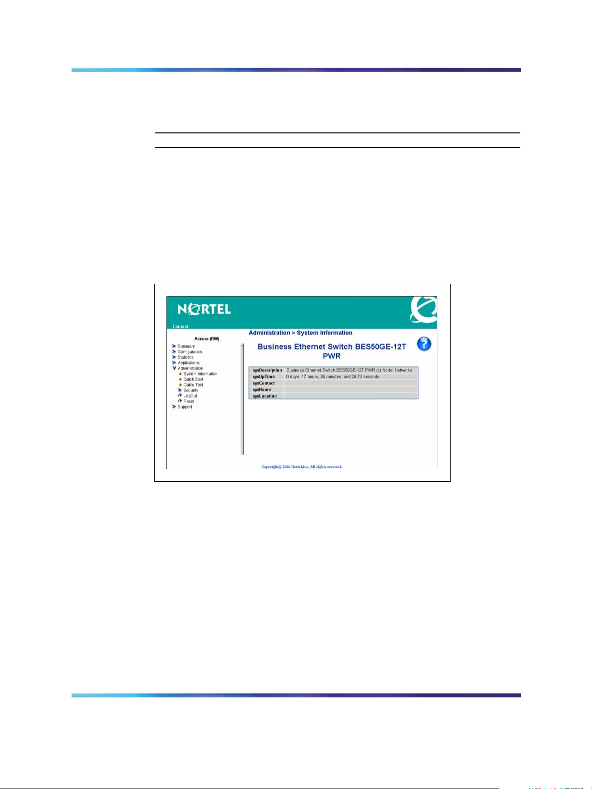
Navigating the Web-based user interface
When your Web browser connects with the switch Web agent, the home
page appears as shown in the figure "Home page" (page 20). The home
page displays the main menu on the left side of the screen and System
Information on the right side. Use the main menu links to navigate to other
menus and display configuration parameters and statistics.
Home page
The figure shows the home page for the BES50GE-12T-PWR 12-port
switch. Other than the number of fixed ports, there are no major differences
between the 12-port and 24-port switch user interface.
Menu and management pages
Using the onboard Web agent, you can define system parameters, manage
and control the switch and all its ports, or monitor network conditions. The
menu is the same for all pages. It contains a list of six main headings. To
navigate the Web-based user interface menu, click a menu title and then
click one of its options. When you click an option, the corresponding page
appears.
Using the Nortel Business Ethernet Switch 50 Series
Copyright © 2006, Nortel Networks Nortel Networks Confidential
.
NN47924-301 01.01 Standard
1.00 October 2006
SMB
Page 21
The first five headings provide options for viewing and configuring switch
parameters. The Support heading provides options to open the online
Help file. Tools are provided in the menu to assist you in navigating the
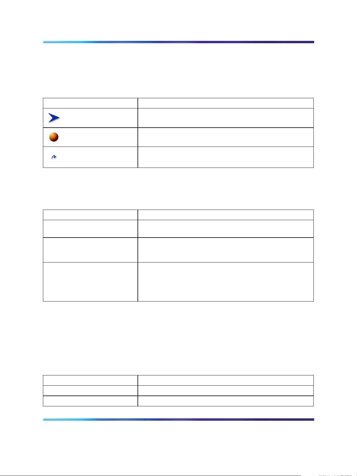
Web-based user interface.
Menu icons
Icon Description
This icon identifies a menu title. Click on this icon to display
its options.
This icon identifies a menu title option. Click on this icon to
display the corresponding page.
This icon is linked to an action, for example, logout, reset, or
reset to system defaults.
When you click a menu option, the corresponding management page
appears. A page is composed of one or more items.
Management page items
Navigating the Web-based user interface 21
Item Description
Tables and input forms Gray cells are read-only.
White cells are input fields.
Check boxes Enable or disable a selection by selecting or clearing a check
box. When a check mark appears in the box, that selection is
enabled. You disable a selection by clearing the check box.
Icons and buttons Icons and buttons perform an action concerning the displayed
page or the switch. Some pages include a button that opens
another page or updates the values shown on the current
page. Some pages include icons that initiate an action, such as
reformatting the current displayed data as a bar or pie chart.
Configuration options
Configurable parameters have a dialog box or a drop-down list. After you
make a configuration change on a page, be sure to click the Submit button
to confirm the new setting. The following table summarizes some of the
common configuration buttons that appear throughout the Web-based user
interface pages.
Web Page configuration buttons
Button Action
Submit Saves specified values to the system.
Reload Refreshes the page with current values.
Using the Nortel Business Ethernet Switch 50 Series
Copyright © 2006, Nortel Networks Nortel Networks Confidential
.
NN47924-301 01.01 Standard
1.00 October 2006
SMB
Page 22

22 Using the Web-based user interface
Button Action
Add Adds the selected parameter to the configuration.
Delete Deletes the selected parameter from the configuration.
Remove Removes the selected parameter from the configuration.
Help Links directly to Web Help.
ATTENTION
To ensure proper screen refresh, in the Internet Explorer menu, choose Tools >
Internet Options >General > Temporary Internet Files > Settings and select
Every visit to the page as the setting for Check for newer versions of stored
pages.
Initial configuration
Use this procedure to configure an IP address for the switch.
To use the BES50 management features, you must first configure the
BES50 with an IP address that is compatible with the network where it
is being installed. For simplicity, configure the IP address before you
permanently install the switch.
Procedure steps
Step Action
1
2
3
4
5
6
Place your switch close to the PC that you will use to configure it.
It helps if you can see the front panel of the switch while you work
on your PC.
Connect the Ethernet port of your PC to any port on the front panel
of your switch.
Insert the power adapter into the DC power socket in front of the
switch.
Plug the other end of the power adapter into a grounded, 3-pin
socket, AC power source.
Check the front-panel LEDs as the device powers on to confirm that
the PWR LED is green. If not, check that the power cable is correctly
plugged in.
If the PC IP address is different from the switch but is on the same
subnet, go to the next step. (For example, if the PC and switch both
have addresses that start with 192.168.1.x.) Otherwise, manually
set the IP address for the PC. See "Changing a PC IP address"
(page 96).
Using the Nortel Business Ethernet Switch 50 Series
Copyright © 2006, Nortel Networks Nortel Networks Confidential
.
NN47924-301 01.01 Standard
1.00 October 2006
SMB
Page 23

Changing the administrator password 23
The default IP address is 192.168.1.128, the default subnet mask is
255.255.255.0, and the default gateway is 0.0.0.0.
7
Open your Web browser and enter the address http://192.168.1.128.
If you do not see the logon page, check your IP address and repeat
step 3.
If you are using DHCP service, use the Element Manager to launch
the BES50 Web-based user interface.
8
Enter the default user name nnadmin and default password
PlsChgMe!, and click Login.
ATTENTION
If you are using DHCP service, skip the remaining steps.
9
10 On the IP Configuration page, enter the new IP address, subnet
11
No other configuration changes are required at this stage, but Nortel
recommends that you change the administrator password before you log off.
From the main menu, click Configuration > IP.
mask and gateway IP address.
Click Submit.
—End—
Changing the administrator password
Use the User Accounts page to change the switch access passwords.
Procedure steps
Step Action
1
2
3
4
Copyright © 2006, Nortel Networks Nortel Networks Confidential
.
From the main menu, choose Administration > Security > User
Accounts.
In the Change Password table, enter the user name for the account
whose password you want to change.
Type in the new password and retype the new password in the
Confirm Password field.
Click Change Password.
—End—
SMB
Using the Nortel Business Ethernet Switch 50 Series
NN47924-301 01.01 Standard
1.00 October 2006
Page 24

24 Using the Web-based user interface
Adding system information
Use the System page to provide a descriptive name, location, and contact
information for the system.
Procedure steps
Step Action
1 From the main menu, choose Configuration > System.
2
3
Type a contact name, system name, and system location information.
Click Submit.
—End—
Variable definitions
Variable Value
System Description Description of the switch.
System Object ID This read-only parameter is the Management Information Base
(MIB) II object ID for the switch network management subsystem.
System Up Time Length of time the management agent has been operational.
System Contact Administrator responsible for the system.
System Name Name assigned to the switch system.
Location The system location.
Setting the IP address
You can use an IP address to manage access to the switch over your
network. By default, the switch uses Dynamic Host Configuration Protocol
(DHCP) to assign IP settings to the management VLAN. (Default: VLAN
1.) If you want to manually configure IP settings, the IP address and subnet
mask must be compatible with your network. You may also need to establish
a default gateway between the switch and management stations that exist
on another network segment.
You can manually configure a specific IP address or direct the device to
obtain an address from a Bootstrap Protocol (BOOTP) or DHCP server.
Valid IP addresses consist of four decimal numbers, 0 to 255, separated by
periods. This is the only format that the Web-based user interface accepts.
Navigation
•
"Setting the IP address manually" (page 25)
•
"Setting the IP address automatically" (page 25)
Using the Nortel Business Ethernet Switch 50 Series
Copyright © 2006, Nortel Networks Nortel Networks Confidential
.
NN47924-301 01.01 Standard
1.00 October 2006
SMB
Page 25

Setting the IP address manually
Use the IP Configuration page to set the IP address manually.
Procedure steps
Step Action
Setting the IP address 25
1
2
From the main menu, choose Configuration > IP.
Select the VLAN through which the management station is attached.
3 In the IP Address Mode box, select Static .
4
5
6
Type the IP address, subnet mask, and gateway IP address.
Click Submit.
To save the changes, close the Web-based user interface and start a
new session by using the new IP address.
Setting the IP address automatically
Use the IP Configuration page to set the IP address dynamically and to
request an IP address from the DHCP server.
Prerequisites
•
To configure the switch dynamically, the network must provide DHCP
or BOOTP services.
—End—
Procedure steps to set the IP address automatically
Step Action
1
2
3
4
From the main menu, choose Configuration > IP.
Select the VLAN through which the management station is attached.
In the IP Address Mode box, select DHCP or BOOTP.
Click Submit to save the setting and get the new IP address from
the DHCP server.
The switch broadcasts a request for IP configuration settings on
each power reset.
—End—
Using the Nortel Business Ethernet Switch 50 Series
Copyright © 2006, Nortel Networks Nortel Networks Confidential
.
NN47924-301 01.01 Standard
1.00 October 2006
SMB
Page 26

26 Using the Web-based user interface
Procedure steps to manually request an IP address from the DHCP
server
Step Action
1
2
From the main menu, choose Configuration > IP.
Click Restart DHCP to immediately request a new address.
The switch broadcasts a request for IP configuration settings on
each power reset.
—End—
Variable definitions
Variable Value
Management VLAN ID of the configured VLAN (Range: 1 to 4094).
This is the only VLAN through which you can gain management
access to the switch. By default, all ports on the switch
are members of VLAN 1, so a management station can be
connected to any port on the switch. However, if other VLANs
are configured and you change the management VLAN, you
can lose management access to the switch. In this case,
reconnect the management station to a port that is a member
of the management VLAN.
IP Address Mode Select the configuration method.
If you select DHCP or BOOTP, the IP address does not function
until a reply is received from the server. The switch periodically
broadcasts a request for an IP address.
IP Address For Static IP Address Mode, enter the IP address of the
management access VLAN interface.
Valid IP addresses consist of four numbers, 0 to 255, separated
by periods. (Default: 192.168.1.128)
Subnet Mask For Static IP Address Mode, enter the host address bits used
for routing to specific subnets. (Default: 255.255.255.0)
Gateway IP address For Static IP Address Mode, enter the IP address of the
gateway router between this device and management stations
that exist on other network segments. (Default: 0.0.0.0)
MAC Address The MAC address of this switch.
Restart DHCP Requests a new IP address from the DHCP server.
Using the Nortel Business Ethernet Switch 50 Series
Copyright © 2006, Nortel Networks Nortel Networks Confidential
.
NN47924-301 01.01 Standard
1.00 October 2006
SMB
Page 27

BES50 basic configuration
Use the procedures in this chapter to manage the basic configuration of
your Business Ethernet Switch (BES) 50 Series switch.
Navigation
•
"Configuring initial settings by using the Quick Start feature" (page 27)
•
"Configuring user authentication " (page 29)
•
"Configuring event logging" (page 33)
•
"Setting application filtering" (page 36)
•
"Configuring the system clock" (page 36)
Configuring initial settings by using the Quick Start feature
Use the Quick Start page to quickly set up BES50 features including IP
configuration, Simple Network Management Protocol (SNMP) community,
and trap managers.
27
Procedure steps
Step Action
1
2 Enter and select the data for IP configuration, SNMP community and
3
Copyright © 2006, Nortel Networks Nortel Networks Confidential
.
From the main menu, choose Administration > Quick Start.
trap managers as required by your site.
Click Submit.
—End—
SMB
Using the Nortel Business Ethernet Switch 50 Series
NN47924-301 01.01 Standard
1.00 October 2006
Page 28

28 BES50 basic configuration
Variable definitions
Variable Value
IP Configuration
Management VLAN ID of the configured Virtual Local Area Network (VLAN) (Range:
1 to 4094).
This is the only VLAN through which you can gain management
access to the switch. By default, all ports on the switch
are members of VLAN 1, so a management station can be
connected to any port on the switch. However, if other VLANs are
configured and you change the management VLAN, you can lose
management access to the switch. In this case, reconnect the
management station to a port that is a member of the management
VLAN.
IP Address Mode Select the configuration method.
If you select Dynamic Host Configuration Protocol (DHCP) or
Bootstrap Protocol (BOOTP), the IP address does not function
until a reply is received from the server. The switch periodically
broadcasts a request for an IP address.
IP Address For Static IP Address Mode, enter the IP address of the
management access VLAN interface.
Valid IP addresses consist of four numbers, 0 to 255, separated
by periods. (Default: 192.168.1.128)
Subnet Mask For Static IP Address Mode, enter the host address bits used for
routing to specific subnets. (Default: 255.255.255.0)
Gateway IP address For Static IP Address Mode, enter the IP address of the gateway
router between this device and management stations that exist on
other network segments. (Default: 0.0.0.0)
MAC Address The MAC address of this switch.
SNMP Community:
SNMP Community Capability The number of community strings supported by the BES50.
Current List of currently configured community strings.
Community String Type the name of the community string. The name acts like a
password and permits access to the SNMP protocol.
Default strings: PlsChgMe!RO (read-only access), PlsChgMe!RW
(read/write access). Range: 1 to 32 characters, case-sensitive.
Access Mode Select the access rights for the community string:
•
Read-Only—Authorized management stations can only
retrieve Management Information Base (MIB) objects.
•
Read/Write—Authorized management stations can retrieve
and modify MIB objects.
Trap Managers:
Using the Nortel Business Ethernet Switch 50 Series
Copyright © 2006, Nortel Networks Nortel Networks Confidential
.
NN47924-301 01.01 Standard
1.00 October 2006
SMB
Page 29

Configuring user authentication 29
Variable Value
Trap Manager Capability The number of trap managers supported by the BES50.
Current List of currently configured trap managers.
Trap Manager IP Address Type the IP address of a new management station to receive
notification messages.
Trap Manager Community
String
Specify a valid community string for the new trap manager entry.
(Range: 1 to 32 characters, case-sensitive)
ATTENTION
Nortel recommends that you define this string in the SNMP
Configuratino page for version 1 or 2c clients, or define a
corresponding user name in the SNMPv3 Users page for
version 3 clients.
Trap UDP Port The UDP port number used by the trap manager.
Trap Version Select the SNMP version. (Default: 1)
Trap Security Level For trap version 3, specify one of the following security levels.
(Default: noAuthNoPriv)
•
noAuthNoPriv—SNMP communications do not use
authentication or encryption.
•
AuthNoPriv—SNMP communications use authentication, but
the data is not encrypted (only available for the SNMPv3
security model).
•
AuthPriv—SNMP communications use both authentication
and encryption (only available for the SNMPv3 security
model).
Trap Inform For version 2c and 3 hosts, notifications are sent as inform
messages. (Default: traps are used)
• Timeout—The number of seconds to wait for an
acknowledgment before resending an inform message.
(Range: 0 to 2147483647 centiseconds)
•
Retry times—The maximum number of times to resend an
inform message if the recipient does not acknowledge receipt.
(Range: 0 to 255)
Configuring user authentication
Use the procedures in this section to restrict management access to the
switch and to provide secure network access.
Navigation
•
Use "Configuring user accounts" (page 30) to manually configure
management access rights for users.
Using the Nortel Business Ethernet Switch 50 Series
Copyright © 2006, Nortel Networks Nortel Networks Confidential
.
NN47924-301 01.01 Standard
1.00 October 2006
SMB
Page 30

30 BES50 basic configuration
•
Use "Configuring local and remote logon authentication" (page 31) to
remotely configure users access rights.
•
Use "Configuringportsecurity" (page 32) to Configure secure addresses
for individual ports.
• Use "Configuring 802.1X port authentication" (page 87) to control
access to specific ports.
Configuring user accounts
Use the User Accounts page to manually configure management access
rights for users.
The administrator has write access for all parameters governing the onboard
agent. Assign a new administrator password as soon as possible, and store
it in a safe place.
See "Changing the administrator password" (page 23).
Procedure steps
Step Action
1
From the main menu, choose Administration > Security > User
Accounts.
2 To configure a new user account, enter the user name, access level,
and password. (The default administrator name is nnadmin with
the password PlsChgMe!.)
3
Click Add.
ATTENTION
To change the password for a specific user, enter the user name and new
password, and then confirm the password by entering it again.
—End—
Variable definitions
Variable Value
Account List The current list of user accounts and associated access levels.
(Default user name: nnadmin; default password: PlsChgMe!)
New Account
User Name Enter the name of the user. (Maximum length: 8 characters;
maximum number of users: 16)
Using the Nortel Business Ethernet Switch 50 Series
Copyright © 2006, Nortel Networks Nortel Networks Confidential
.
NN47924-301 01.01 Standard
1.00 October 2006
SMB
Page 31

Configuring user authentication 31
Variable Value
Access Level Select Privileged to configure read/write user access.
Select Normal to configure read-only user access.
Password Enter the user password. (Range: 0 to 8 characters plain text,
case-sensitive)
Confirm Password Enter a new password for the specified user.
Configuring local and remote logon authentication
Use the Authentication Settings page to restrict management access based
on specified user names and passwords. You can manually configure
access rights on the switch, or you can use a remote access authentication
server based on Remote Authentication Dial-In User Server (RADIUS)
protocols.
Procedure steps
Step Action
1
From the main menu, choose Administration > Security >
Authentication Settings.
2
To configure local or remote authentication preferences, select the
authentication sequence from the Authentication list (one to two
methods).
3
4
For RADIUS authentication, fill in the required parameters.
Click Apply.
—End—
Variable definitions
Variable Value
Authentication Select the authentication or authentication sequence:
•
Local—The switch performs user authentication locally.
•
RADIUS—The RADIUS performs user authentication.
• [authentication sequence]—User authentication occurs in the
indicated sequence. (Local/RADIUS or RADIUS/Local)
RADIUS Settings Select the authentication or authentication sequence:
•
Global—Provides globally applicable RADIUS settings.
Using the Nortel Business Ethernet Switch 50 Series
Copyright © 2006, Nortel Networks Nortel Networks Confidential
.
NN47924-301 01.01 Standard
1.00 October 2006
SMB
Page 32

32 BES50 basic configuration
Variable Value
•
ServerIndex—Specifies one of five RADIUS servers that can
be configured. The switch attempts authentication by using the
listed sequence of servers. The process ends when a server
either approves or denies access to a user.
• Server Port Number—Network (UDP) port of authentication
server used for authentication messages. (Range: 1 to 65535;
Default: 1812)
•
Secret Text String—Encryption key used to authenticate logon
access for the client. Do not use blank spaces in the string.
(Maximum length: 20 characters)
• Number of Server Transmits—Number of times the switch tries
to authenticate logon access through the authentication server.
(Range: 1 to 30; Default: 2)
•
Timeout for a reply—The number of seconds the switch waits
for a reply from the RADIUS server before it resends the
request. (Range: 1 to 65535; Default: 5)
Configuring port security
Use the Port Security page to configure secure addresses for individual
ports.
Using the port security feature, you can configure a switch port with one or
more device MAC addresses authorized to access the network through
that port.
To use port security, specify a maximum number of addresses to allow on
the port and then let the switch dynamically learn the source pair—MAC
address, VLAN—for frames received on the port. See "Configuring 802.1X
port settings" (page 88). You can also manually add secure addresses to the
port by using the Static Address table. See "Setting static addresses" (page
85). When the port reaches the maximum number of MAC addresses, the
selected port stops learning. The MAC addresses already in the address
table are retained and do not age out. Any other device that attempts to use
the port is prevented from accessing the switch.
A secure port:
•
cannot use port monitoring
•
cannot be a multi-VLAN port
•
cannot be used as a member of a static or dynamic trunk
•
should not be connected to a network interconnection device
Using the Nortel Business Ethernet Switch 50 Series
Copyright © 2006, Nortel Networks Nortel Networks Confidential
.
NN47924-301 01.01 Standard
1.00 October 2006
SMB
Page 33

Configuring event logging 33
ATTENTION
If a port is disabled (shut down) due to a security violation, it must be manually
reenabled from the Port/Port Configuration page.
Procedure steps
Step Action
1
From the main menu, choose Administration > Security > Port
Security.
2 Select the check box in the Security Status column to enable
security for a port.
3
Click Submit.
—End—
Variable definitions
Variable Value
Port Port number.
Name Descriptive text.
Security Status Select to enable port security on the port. (Default: Disabled)
Trunk Trunk number if port is a member.
LACP Indicates whether Link Aggregation Control Protocol (LACP) is
enabled or disabled.
Configuring event logging
Use these procedures to control the logging of error messages, including
the type of events recorded in switch memory, and logging to a remote
System Log (syslog) server.
Navigation
•
"Configuring the system logs" (page 33)
•
"Configuring the remote logs" (page 35)
Configuring the system logs
Use the System Logs page to configure system messages logged to flash
or RAM memory.
Using the Nortel Business Ethernet Switch 50 Series
Copyright © 2006, Nortel Networks Nortel Networks Confidential
.
NN47924-301 01.01 Standard
1.00 October 2006
SMB
Page 34

34 BES50 basic configuration
Severe error messages logged to flash memory are permanently stored in
the switch to assist in troubleshooting network problems. The flash memory
can store up to 4096 log entries with the oldest entries being overwritten
first when the available log memory exceeds 256 kilobytes.
Procedure steps
Step Action
1
2
3
From the main menu choose Configuration > Log > System Logs.
Select the System Log Status Enabled check box.
Type the event level for flash and RAM. See the "Event level
messages table" (page 34).
ATTENTION
The flash level must not exceed the RAM level.
4
Variable definitions
Variable Value
System Log Status Select to enable the logging of debug or error messages to the
Flash Level Enter the highest level of log message to save to the switch
Click Submit.
—End—
logging process.
permanent flash memory. For example, specify level 3 to log all
messages from level 0 to level 3 to flash. (Range: 0 to 7. Default:
3)
RAM Level Enter the highest level of log message to save to the switch
temporary RAM memory. For example, specify level 7 to log all
messages from level 0 to level 7 to RAM. (Range: 0 to 7. Default:
7)
Event level messages table
Level
7
6
5
4
Copyright © 2006, Nortel Networks Nortel Networks Confidential
.
Severity
Name
Debug Debugging messages
Informational Informational messages only
Notice Normal but significant condition, such as cold start
Warning Warning conditions (such as return false, or unexpected
Using the Nortel Business Ethernet Switch 50 Series
Description
return)
SMB
NN47924-301 01.01 Standard
1.00 October 2006
Page 35

Configuring event logging 35
Level
3
2
1
0
Severity
Name
Error Error conditions (such as invalid input, or default used)
Critical Critical conditions (such as memory allocation, or free
Alert Immediate action needed
Emergency System unusable
Description
memory error—resource exhausted)
Configuring the remote logs
Use the Remote Logs page to configure message logging to remote
servers. You can also limit the error messages sent to only those messages
below a specified level.
Procedure steps
Step Action
1
2
3
Fromthe main menu, choose Configuration > Log > Remote Logs.
For Remote Log Status, select the Enabled check box.
In the Logging Facility and the Logging Trap fields, type the event
level.
4
To add an IP address to the Host IP List, type the new IP address in
the Host IP Address box, and then click Add.
5
To delete an IP address, click the entry in the Host IP List, and then
click Remove.
6
Click Submit.
—End—
Variable definitions
Variable Value
Remote Logs
Remote Log Status Select to enable the logging of debug or error messages to the
remote logging process. (Default: Disabled)
Logging Facility Type the facility type tag to send in syslog messages. The facility
type is used by the syslog server to dispatch log messages to
an appropriate service, and to sort or store messages in the
corresponding database. (Range: 16 to 23. Default: 23)
Using the Nortel Business Ethernet Switch 50 Series
Copyright © 2006, Nortel Networks Nortel Networks Confidential
.
NN47924-301 01.01 Standard
1.00 October 2006
SMB
Page 36

36 BES50 basic configuration
Variable Value
Logging Trap Enterthe highest level of log message to send to the remote syslog
server. For example, specify level 3 to send all messages from
level 0 to level 3 to the remote server. (Range: 0 to 7. Default: 7)
Host IP Address
Host IP List List of remote server IP addresses that receive the syslog
messages. The maximum number of host IP addresses allowed
is five.
Host IP Address Enter the server IP address to add to the Host IP List.
Setting application filtering
Use this procedure to set access control on the switch. The BES50 provides
security control features and controls the access modes, consequently
preventing illegal users from logging on to and accessing switches.
Procedure steps
Step Action
1
2
From the main menu, choose Applications > Application Filtering.
For each port, select the appropriate check boxes to enable the
required access.
3
Variable definitions
Variable Value
FTP Select to enable filtering.
SSH Select to enable filtering.
TELNET Select to enable filtering.
TFTP Select to enable filtering.
HTTP Select to enable filtering.
HTTPs Select to enable filtering.
Click Submit.
Configuring the system clock
Use the Applications Simple Network Time Protocol (SNTP) page to
configure the system clock manually or automatically, and to configure
daylight saving time on the BES50.
—End—
Using the Nortel Business Ethernet Switch 50 Series
Copyright © 2006, Nortel Networks Nortel Networks Confidential
.
NN47924-301 01.01 Standard
1.00 October 2006
SMB
Page 37

Navigation
•
"Setting the system clock" (page 37)
•
"Setting daylight saving time" (page 37)
Setting the system clock
Use this procedure to set the system clock manually or automatically.
Manually set system time is not maintained upon reset of the BES50 hardware
or software.
Procedure steps
Step Action
Configuring the system clock 37
ATTENTION
1
2
From the main menu, choose Applications > SNTP.
To set time manually:
a. Select Set the system time manually.
b. In the Manual table, type the value for each of the Hours,
Minutes, Seconds, Month, Day, and Year fields.
ATTENTION
The Year field must be at least 2001.
3
4
To set time automatically:
a. Select Set the system time using Simple Network Time
Protocol (SNTP) automatically.
b. From the Time Zone list, select the appropriate time zone.
c. Complete the settings in the Automatic and SNTP Server tables
as required.
See "Setting daylight saving time" (page 37) for details.
Click Submit.
—End—
Setting daylight saving time
Use this procedure to configure daylight saving time on the BES50.
Prerequisites
•
Select the automatic system time configuration option.
Using the Nortel Business Ethernet Switch 50 Series
Copyright © 2006, Nortel Networks Nortel Networks Confidential
.
NN47924-301 01.01 Standard
1.00 October 2006
SMB
Page 38

38 BES50 basic configuration
Procedure steps
Step Action
1
From the main menu, choose Applications > SNTP.
2 In the Automatic table, select the Daylight Saving check box, and
then select the daylight saving configuration type. (USA, Europe,
Custom)
3
In the Time Set Offset field, type the number of minutes to offset the
original time to achieve daylight saving time. (This value is typically
set to 60 minutes.)
4
If you select Custom as the daylight saving configuration type, type
the startand end date and time in the FROM and TO fields, or select
the Recurring check box to configure a custom recurring daylight
saving time.
5
Click Submit.
—End—
Variable definitions
Variable Value
Set Time Select the method for setting the system time. (Options: set
the system time manually or set the system time automatically
using SNTP.)
Manual For manual time setting, enter the time and date.
If the time is set manually, the system clock resets each time
the switch is rebooted.
Automatic For automatic time setting, configure the switch so the SNTP
automatically sets the time and date. Enter the values for the
parameters as required.
•
Time Zone—Select your time zone.
•
Daylight Saving—Select the daylight saving configuration
type. (Options: USA, Europe, or Custom)
•
Time Set Offset—For custom settings, enter the time offset
from the time zone.
•
Recurring—Select to use the daylight saving feature for a
specific time period.
•
From/To—Enter the applicable dates and times for daylight
saving use.
Using the Nortel Business Ethernet Switch 50 Series
Copyright © 2006, Nortel Networks Nortel Networks Confidential
.
NN47924-301 01.01 Standard
1.00 October 2006
SMB
Page 39

Configuring the system clock 39
Variable Value
Server 1/Server 2 For automatic time setting, type the IP address for up to two
SNTP servers. The switch attempts to update the time from
the first server; if this fails, it attempts an update from the
second server.
Polling Interval For automatic time setting, select the interval between sending
requests for a time update from a time server. (Range: 16 to
16384 seconds. Default: 16 seconds)
Using the Nortel Business Ethernet Switch 50 Series
Copyright © 2006, Nortel Networks Nortel Networks Confidential
.
NN47924-301 01.01 Standard
1.00 October 2006
SMB
Page 40

40 BES50 basic configuration
Using the Nortel Business Ethernet Switch 50 Series
SMB
NN47924-301 01.01 Standard
Copyright © 2006, Nortel Networks Nortel Networks Confidential
.
1.00 October 2006
Page 41

41
BES50 advanced features configuration
Use these procedures to set up the Business Ethernet Switch (BES) 50
advanced management features.
Navigation
•
"Configuring Simple Network Management Protocol" (page 42)
•
"Configuring ports and trunks" (page 55)
•
"Creating trunk groups" (page 56)
•
"Setting broadcast storm thresholds" (page 60)
•
"Configuring port mirroring" (page 61)
•
"Configuring rate limits" (page 62)
•
"Setting Power over Ethernet" (page 63)
• "Configuring Spanning Tree Algorithm " (page 65)
•
"Configuring IEEE 802.1Q VLANs" (page 69)
•
"Link Layer Discovery Protocol (LLDP) configuration" (page 75)
• "Configuring Class of Service " (page 76)
•
"Configuring Quality Of Service (QoS)" (page 81)
•
"Configuring address tables" (page 84)
• "Voice VLAN configuration" (page 85)
•
"Configuring 802.1X port authentication" (page 87)
•
"Configuring Access Control Lists " (page 90)
Using the Nortel Business Ethernet Switch 50 Series
Copyright © 2006, Nortel Networks Nortel Networks Confidential
.
NN47924-301 01.01 Standard
1.00 October 2006
SMB
Page 42

42 BES50 advanced features configuration
Configuring Simple Network Management Protocol
Use these procedures to set up Simple Network Management Protocol
(SNMP) and security on your BES50.
Navigation
•
"Sending an inform message to an SNMP version 2 host" (page 42)
• "Sending an inform message to an SNMP version 3 host" (page 42)
•
"Setting community access strings" (page 43)
•
"Specifying trap managers and trap types" (page 43)
• "Enabling SNMP service" (page 46)
•
"Configuring SNMP version 3 management access" (page 46)
Sending an inform message to an SNMP version 2 host
You can send an inform message to an SNMP version 2 host by completing
the following procedures.
1. Enable the SNMP agent. See "Enabling SNMP service" (page 46).
2. Enable trap inform messages. See "Specifying trap managers and trap
types" (page 43).
3. Create a view with the required notification messages. See "Setting
SNMP version 3 views" (page 48).
4. Create a group that includes the required notify view. See "Creating
SNMP version 3 groups" (page 52).
Sending an inform message to an SNMP version 3 host
You can send an inform message to an SNMP version 3 host by completing
the following procedures.
1. Enable the SNMP agent. See "Enabling SNMP service" (page 46).
2. Enable trap inform messages. See "Specifying trap managers and trap
types" (page 43).
3. Create a view with the required notification messages. See "Setting
SNMP version 3 views" (page 48).
4. Create a group that includes the required notify view. See "Creating
SNMP version 3 groups" (page 52).
5. Specify a remote engine ID where the user resides. See "Setting a
remote engine ID" (page 47).
6. Configure a remote user. See "Configuring remote SNMP version 3
users" (page 51).
Using the Nortel Business Ethernet Switch 50 Series
Copyright © 2006, Nortel Networks Nortel Networks Confidential
.
NN47924-301 01.01 Standard
1.00 October 2006
SMB
Page 43

Configuring Simple Network Management Protocol 43
Setting community access strings
Use this procedure to configure community strings and related trap functions
for clients by using SNMP version 1 and v2c. List all community strings used
for IP trap managers in this table, to a maximum of five.
For security reasons, Nortel recommends that you remove the default
community strings.
Procedure steps
Step Action
1
From the main menu, choose Configuration > SNMP > SNMP
Configuration.
2
In the SNMP Community table, type a community string and select
an access mode.
3
Click Add to save your configuration settings.
—End—
SNMP Configuration page items
Item Description
SNMP Community Capability The maximum number of community strings that the BES50
supports. (Maximum number supported: 5)
Current List of currently configured community strings.
Community String Type the name of the community string. The name acts like a
password and permits access to the SNMP protocol. (Default
strings: PlsChgMe!RO [read-only access], PlsChgMe!RW
[read/write access]. Range: 1 to 32 characters, case-sensitive.)
Access Mode Specify the access rights for the community string:
• Read-Only—Authorized management stations can only
retrieve Management Information Base (MIB) objects.
•
Read/Write—Authorized management stations can retrieve
and modify MIB objects.
Specifying trap managers and trap types
Use the SNMP Configuration page to specify trap managers.
The switch issues traps indicating status changes to specified trap
managers. You must specify trap managers so the switch reports key events
to your management station by using network management platforms such
Using the Nortel Business Ethernet Switch 50 Series
Copyright © 2006, Nortel Networks Nortel Networks Confidential
.
NN47924-301 01.01 Standard
1.00 October 2006
SMB
Page 44

44 BES50 advanced features configuration
as the Element Manager. You can specify up to five management stations
to receive authentication failure messages and other notification messages
from the switch.
By default, the switch issues notifications as trap messages. The recipient
of a trap message does not send a response to the switch. Therefore,
traps are not reliable as inform messages, which include a request for
acknowledgement of receipt. Informs can be used to ensure that the host
receives critical information. However, inform messages consume more
system resources because they must be kept in memory until a response is
received. Inform messages also add to network traffic.
If you specify an SNMP version 3 host, then the Trap Manager Community
String is interpreted as an SNMP user name. If you use SNMP version 3
authentication or encryption options (authNoPriv or authPriv), you must
first define the user name in the SNMP version 3 Users page to enable
password authentication and SNMP access to the switch. However, if
you specify a SNMP version 3 host with the no authentication (noAuth)
option, an SNMP user account is automatically generated, and the switch
authorizes SNMP access for the host.
Prerequisites
•
For SNMP version 3 authentication or encryption options (authNoPriv or
authPriv), you must first define the user name in the SNMP version 3
Users page. See "Configuring SNMP version 3 users" (page 49).
Procedure steps
Step Action
1
2
3
4
5
6
From the main menu, choose Configuration > SNMP > SNMP
Configuration.
In the Trap Managers table, enter a trap manager IP address and
trap manager community string for each management station that
receives trap messages.
For SNMP version 2 and version 3 clients, specify the trap inform
message settings.
For SNMP version 3 clients, specify the UDP port, trap version, and
trap security level.
Click Add.
Select the check boxes for Enable Authentication and Enable
Link-up and Link-down Traps to indicate the trap types.
7
Copyright © 2006, Nortel Networks Nortel Networks Confidential
.
Click Submit.
SMB
Using the Nortel Business Ethernet Switch 50 Series
NN47924-301 01.01 Standard
1.00 October 2006
Page 45

Configuring Simple Network Management Protocol 45
—End—
Variable definitions
Variable Value
Trap Manager Capability The number of trap managers that the BES50 supports.
Current List of currently configured trap managers.
Trap Manager IP Address Type the IP address of a new management station to receive
notification messages.
Trap Manager Community
String
Specify a valid community string for the new trap manager entry.
(Range: 1 to 32 characters, case-sensitive.)
ATTENTION
Nortel recommends that you define this string in the SNMP
Configuration page for Version 1 or 2c clients, or define a
corresponding user name in the SNMP version 3 Users page
for Version 3 clients.
Trap UDP Port The UDP port number used by the trap manager.
Trap Version Select the SNMP version. (Default: 1)
Trap Security Level For trap version 3, specify one of the following security levels.
(Default: noAuthNoPriv)
•
noAuthNoPriv—SNMP communications do not use
authentication or encryption.
•
AuthNoPriv—SNMP communications use authentication, but
the data is not encrypted.
• AuthPriv—SNMP communications use both authentication
and encryption.
Trap Inform For version 2c and 3 hosts, notifications are sent as inform
messages. (Default: traps are used)
•
Timeout—The number of seconds to wait for an
acknowledgment before resending an inform message.
(Range: 0 to 2 147 483 647 centiseconds)
•
Retry times—The maximum number of times to resend an
inform message if the recipient does not acknowledge receipt.
(Range: 0 to 255)
Enable Authentication Traps Select to issue a notification message to specified IP trap
managers whenever authentication of an SNMP request fails.
(Default: Enabled)
Enable Link-up and
Link-down Traps
Using the Nortel Business Ethernet Switch 50 Series
Copyright © 2006, Nortel Networks Nortel Networks Confidential
.
Select to issue a notification message whenever a port link is
established or broken. (Default: Enabled)
SMB
NN47924-301 01.01 Standard
1.00 October 2006
Page 46

46 BES50 advanced features configuration
Enabling SNMP service
Use the SNMP Agent page to enable SNMP service for all management
clients (versions 1, 2c, 3).
Procedure steps
Step Action
1
From the main menu, choose Configuration > SNMP > Agent
Status.
2
3
Select the Enable check box.
Click Submit.
—End—
Variable definitions
Variable Value
SNMP Agent Status Select to enable SNMP on the switch.
Configuring SNMP version 3 management access
Use these procedures to configure SNMP version 3 management access to
the BES50.
Navigation
•
"Setting the local engine ID" (page 46)
•
"Setting a remote engine ID" (page 47)
•
"Setting SNMP version 3 views" (page 48)
•
"Configuring SNMP version 3 users" (page 49)
•
"Changing the assigned group for an SNMP version 3 user" (page 50)
•
"Configuring remote SNMP version 3 users" (page 51)
•
"Creating SNMP version 3 groups" (page 52)
Setting the local engine ID
Use this procedure to set the SNMP version 3 engine ID on the BES50 if it
is different from the default value or if it has been deleted.
ATTENTION
If this local default engine ID is deleted or changed, all SNMP users are cleared
and all existing users must be reconfigured.
Using the Nortel Business Ethernet Switch 50 Series
Copyright © 2006, Nortel Networks Nortel Networks Confidential
.
NN47924-301 01.01 Standard
1.00 October 2006
SMB
Page 47

Configuring SNMP version 3 management access 47
Prerequisites
•
Change the default engine ID before you configure other parameters.
Procedure steps
Step Action
1
From the main menu, choose Configuration > SNMPv3 > Engine
ID.
2
Type an engine ID, to a maximum of 26 hexadecimal characters.
If you specify fewer than 26 characters, trailing zeroes are added
to the value. For example, the value 1234 is equivalent to 1234
followed by 22 zeroes.
3
Click Save.
Setting a remote engine ID
Use the Remove Engine ID page to set the SNMP version 3 engine ID
for a remote device.
To send inform messages to an SNMP version 3 user on a remote device,
you must first specify the engine identifier for the SNMP agent on the remote
device where the user resides. The remote engine ID is used to compute
the security digest for authenticating and encrypting packets sent to a user
on the remote host.
—End—
SNMP passwords are localized by using the engine ID of the authoritative
agent. For inform messages, the authoritative SNMP agent is the remote
agent. You therefore need to configure the remote agent SNMP engine ID
before you can send proxy requests or inform messages to it.
Prerequisites
•
Change the default engine ID before you configure other parameters.
Procedure steps
Step Action
1
2
Copyright © 2006, Nortel Networks Nortel Networks Confidential
.
From the main menu, choose Configuration > SNMPv3 > Remote
Engine ID.
Type an engine ID, to a maximum of 26 hexadecimal characters.
SMB
Using the Nortel Business Ethernet Switch 50 Series
NN47924-301 01.01 Standard
1.00 October 2006
Page 48

48 BES50 advanced features configuration
If you specify fewer than 26 characters, trailing zeroes are added
to the value. For example, the value 1234 is equivalent to 1234
followed by 22 zeroes.
3
4
Type an IP address for the remote host.
Click Add.
Setting SNMP version 3 views
Use this procedure to restrict user access to specified portions of the
Management Information Base (MIB) tree. The predefined view defaultview
includes access to the entire MIB tree.
Procedure steps
Step Action
1
2
3
From the main menu, choose Configuration > SNMPv3 > Views.
Click New.
In the SNMPv3 View—Edit page, for each Object Identifier (OID)
subtree, type a view name and select the type to specify which OID
subtrees to include or exclude.
—End—
4
5
Click Add to save the new view.
Click Back to return to the SNMPv3 Views list.
—End—
Variable definitions—SNMPv3 View—Edit page
Variable Value
View Name Type the name of the SNMP view. (Range: 1 to 64 characters)
Current The listing of OID subtrees configured for the selected SNMP
version 3 view.
Using the Nortel Business Ethernet Switch 50 Series
Copyright © 2006, Nortel Networks Nortel Networks Confidential
.
NN47924-301 01.01 Standard
1.00 October 2006
SMB
Page 49

Configuring SNMP version 3 management access 49
Variable Value
OID Subtrees Type the object identifier of the MIB tree branch that defines the
SNMP view.
Type Select to indicate whether the object identifier of the MIB tree
branch is included in or excluded from the SNMP view.
Variable definitions—SNMPv3 Views page
Variable Value
[check box column] Select the check box for each SNMP version 3 view that you want
to view or delete.
Name The name of the SNMP view. (Range: 1 to 64 characters)
OID Subtrees Click the hyperlink to view details of the currently configured object
identifiers of the MIB tree branch that defines the SNMP view.
Configuring SNMP version 3 users
Use this procedure to assign SNMP version 3 users to groups.
A unique name defines each SNMP version 3 user. Each user must be
configured with a specific security level and assigned to a group (community
access string). The SNMP version 3 group restricts users to a specific read,
write, and notify view.
Procedure steps
Step Action
1
2
3
4
5
From the main menu, choose Configuration > SNMPv3 > Users.
Click New.
In the SNMPv3 Users—New page, type a name for the user and
assign the user to a group.
If required, select the Security Model and Level, User
Authentication, and Data Privacy settings for the user.
Click Submit to save the configuration and return to the User Name
list.
—End—
Using the Nortel Business Ethernet Switch 50 Series
Copyright © 2006, Nortel Networks Nortel Networks Confidential
.
NN47924-301 01.01 Standard
1.00 October 2006
SMB
Page 50

50 BES50 advanced features configuration
Variable definitions
Variable Value
User Name Type the name of the user connecting to the SNMP agent.
(Range: 1 to 32 characters)
Group Name Type the name of the SNMP group to which the user is assigned
or select a preexisting group name from the list. (Range: 1 to
32 characters)
Security Model Select the user security model. (SNMP v1, v2c, or v3.)
Security Level For security model 3, select the security level used:
•
noAuthNoPriv—SNMP communications do not use
authentication or encryption. (Default)
•
AuthNoPriv—SNMP communications use authentication, but
the data is not encrypted.
•
AuthPriv—SNMP communications use both authentication
and encryption.
Authentication For AuthNoPriv or AuthPriv security level, select the user
authentication method. (Options: MD5, SHA. Default: MD5)
Authentication Password For AuthNoPriv or AuthPriv security level, type an authorization
password with a minimum of eight plain text characters.
Privacy The encryption algorithm used for data privacy; only 56-bit DES is
currently available.
Changing the assigned group for an SNMP version 3 user
Use the SNMPv3 Users page to change the assigned group of an SNMP
version 3 user.
Procedure steps
Step Action
1
2
3
4
From the main menu, choose Configuration > SNMPv3 > Users.
In the Actions column for the user that you wish to update, click
Change Group.
On the SNMPv3 Users-Edit table, click the option button and enter
the name of a new group, or click the option button and select an
existing group from the list.
Click Submit.
—End—
Using the Nortel Business Ethernet Switch 50 Series
Copyright © 2006, Nortel Networks Nortel Networks Confidential
.
NN47924-301 01.01 Standard
1.00 October 2006
SMB
Page 51

Configuring SNMP version 3 management access 51
Configuring remote SNMP version 3 users
Use this procedure to assign remote SNMP version 3 users to groups. The
remote engine ID is used to compute the security digest for authenticating
and encrypting packets sent to a user on the remote host.
Prerequisites
•
Specify the engine identifier for the SNMP agent on the remote device
where the user resides. See "Setting a remote engine ID" (page 47).
Procedure steps
Step Action
1
From the main menu, choose Configuration > SNMPv3 > Remote
Users.
2
3
Click New.
If the remote engine ID is not configured, the Remote Engine ID
dialog box appears. Click OK to access the Remote Engine ID
configuration page. See "Setting a remote engine ID" (page 47) to
configure the remote engine ID before proceeding to the next step.
4
In the Remote Users—New page, type a name for the user and
assign the user to a group.
5
Select the Security Model and Level, User Authentication, and
Data Privacy settings for the user.
6
Variable definitions
Variable Value
Click Submit.
—End—
User Name Type the name of the user connecting to the SNMP agent.
(Range: 1 to 32 characters)
Group Name Type the name of the SNMP group to which the user is assigned
or select a preexisting group name from the list. (Range: 1 to
32 characters)
Using the Nortel Business Ethernet Switch 50 Series
Copyright © 2006, Nortel Networks Nortel Networks Confidential
.
NN47924-301 01.01 Standard
1.00 October 2006
SMB
Page 52

52 BES50 advanced features configuration
Variable Value
Engine IP Select the engine identifier for the SNMP agent on the remote
device where the remote user resides. You must specify the
remote engine identifier before you configure a remote user. (See
"Setting a remote engine ID" (page 47))
Security Model The user security model.
Security Level The security level used for the user:
•
noAuthNoPriv—SNMP communications use no authentication
or encryption.
•
AuthNoPriv—SNMP communications use authentication, but
the data is not encrypted.
• AuthPriv—SNMP communications use both authentication
and encryption.
Authentication Protocol Select the user authentication method. (Options: MD5, SHA;
Default: MD5)
Authentication Password Type an authorization password with a minimum of eight plain
text characters.
Privacy Protocol The encryption algorithm use for data privacy; only 56-bit DES is
currently available.
Privacy Password Type a privacy password with a minimum of eight plain text
characters.
Creating SNMP version 3 groups
An SNMP version 3 group sets the access policy for its assigned users,
restricting them to specific read, write, and notify views. You can use the
predefined default groups or create new groups to map a set of SNMP
users to SNMP views.
Procedure steps
Step Action
1
2
3
4
From the main menu, choose Configuration > SNMPv3 > Groups.
Click New.
In the New Group page, type a group name, and select a security
model and level and the SNMP version 3 views.
Click Submit.
—End—
Using the Nortel Business Ethernet Switch 50 Series
Copyright © 2006, Nortel Networks Nortel Networks Confidential
.
NN47924-301 01.01 Standard
1.00 October 2006
SMB
Page 53

Configuring SNMP version 3 management access 53
Variable definitions
Variable Value
Group Name Type the name of the SNMP group. (Range: 1 to 32 characters)
Security Model Select the group security model. (SNMP v1, v2c, or v3.)
Security Level For security model 3, select the security level used:
•
noAuthNoPriv—SNMP communications do not use
authentication or encryption. (Default)
•
AuthNoPriv—SNMP communications use authentication, but
the data is not encrypted.
•
AuthPriv—SNMP communications use both authentication
and encryption.
Read View Click the upper option button and type a name for the read access
view, or click the lower option button and select the configured
view from the list. (Range: 1 to 64 characters)
Write View Click the upper option button and type a name for the write access
view, or click the lower option button and select the configured
view from the list. (Range: 1 to 64 characters)
Notify View Click the upper option button and type a name for notifications, or
click the lower option button and select the configured view from
the list. (Range: 1 to 64 characters)
Supported notification messages
Object label Object ID
Description
RFC 1493 Traps
newRoot
1.3.6.1.2.1.17.0.1
This trap indicates that the sending agent is the
new Spanning Tree root. A bridge sends the
trap soon after its election as the new root, such
as upon expiration of the Topology Change
Timer immediately subsequent to its election.
topologyChange
1.3.6.1.2.1.17.0.2
This trap indicates that a configured port
transitioned from the Learning state to the
Forwarding state, or from the Forwarding state
to the Discarding state.
This trap is not sent if a newRoot trap is sent
for the same transition.
SNMP version 2 Traps
coldStart
1.3.6.1.6.3.1.1.5.1
This trap indicates that the SNMP version 2
entity, acting in an agent role, is reinitializing
itself and that its configuration may be altered.
Using the Nortel Business Ethernet Switch 50 Series
Copyright © 2006, Nortel Networks Nortel Networks Confidential
.
NN47924-301 01.01 Standard
1.00 October 2006
SMB
Page 54

54 BES50 advanced features configuration
Object label Object ID
warmStart
linkDown
linkUp
authenticationFailure
1.3.6.1.6.3.1.1.5.2
1.3.6.1.6.3.1.1.5.3
1.3.6.1.6.3.1.1.5.4
1.3.6.1.6.3.1.1.5.5
Description
This trap indicates that the SNMP version 2
entity, acting in an agent role, is reinitializing
itself such that its configuration is unaltered.
This trap indicates that the SNMP entity, acting
in an agent role, detects that the ifOperStatus
object for one of its communication links is
about to enter the down state from some other
state (but not from the notPresent state). This
other state is indicated by the included value of
ifOperStatus.
This trap indicates that the SNMP entity, acting
in an agent role, detects that the ifOperStatus
object for one of its communication links left the
down state and transitioned into some other
state (but not into the notPresent state). This
other state is indicated by the included value of
ifOperStatus.
These are legacy notifications and therefore
must be enabled in conjunction with the
corresponding traps on the SNMP Configuration
menu.
This trap signifies that the SNMP version 2
entity, acting in an agent role, has received
a protocol message that is not properly
authenticated. While all implementations of the
SNMP version 2 must be capable of generating
this trap, the snmpEnableAuthenTraps object
indicates whether this trap is generated.
These are legacy notifications and therefore
must be enabled in conjunction with the
corresponding traps on the SNMP Configuration
menu.
RMON Events (V2)
risingAlarm
1.3.6.1.2.1.16.0.1
This trap generates when an alarm entry
crosses its rising threshold and generates an
event configured for sending SNMP traps.
fallingAlarm
1.3.6.1.2.1.16.0.2
This trap generates when an alarm entry
crosses its falling threshold and generates an
event configured for sending SNMP traps.
Private Traps
swPowerStatus
ChangeTrap
1.3.6.1.4.1.202.20.28
.63.2.1.0.11.3.6.1.4.1
This trap is sent when the power state changes.
.202.20.41.63.2.1.0.1
Using the Nortel Business Ethernet Switch 50 Series
Copyright © 2006, Nortel Networks Nortel Networks Confidential
.
NN47924-301 01.01 Standard
1.00 October 2006
SMB
Page 55

Configuring ports and trunks 55
Object label Object ID
swIpFilterRejectTrap
swSmtpConnFailure
Trap
pethPsePortOnOff
Notification
pethPsePortPower
MaintenanceStatus
Notification
pethMainPower
UsageOnNotification
pethMainPower
UsageOffNotification
1.3.6.1.4.1.202.20.28
.63.2.1.0.40
1.3.6.1.4.1.202.20.41
.63.2.1.0.40
1.3.6.1.4.1.202.20.28
.63.2.1.0.411.3.6.1.4
.1.202.20.41.63.2.1.0
.41
1.3.6.1.4.1.202.20.41
.63.2.1.0.43
1.3.6.1.4.1.202.20.41
.63.2.1.0.44
1.3.6.1.4.1.202.20.41
.63.2.1.0.45
1.3.6.1.4.1.202.20.41
.63.2.1.0.46
Description
This trap is sent when an incorrect IP address is
rejected by the IP filter.
This trap is triggered if the SMTP system
cannot open a connection to the mail server
successfully.
This notification indicates if a Power Sourcing
Equipment (PSE) port is delivering power to the
Powered Device (PD). This notification is sent
on every status change except in search mode.
This notification indicates a port change status
and is sent on every status change.
This notification indicates that the PSE
Threshold usage indication is on. The power
usage is above the threshold.
This notification indicates that the PSE
Threshold usage indication is off. The power
usage is below the threshold.
Configuring ports and trunks
Use these procedures to configure ports and trunks. In this section, the
term interface describes ports and trunks.
Navigation
•
"Configuring interface connections" (page 55)
•
"Creating trunk groups" (page 56)
Configuring interface connections
Use the Port Configuration or Trunk Configuration page to enable or
disable an interface, to set autonegotiation and the interface capabilities to
advertise, or to manually fix the speed, duplex mode, and flow control.
Procedure steps
Step Action
1
2
From the main menu, choose Configuration > Port > Port
Configuration or choose Configuration > Port > Trunk
Configuration.
Modify the required interface settings.
Using the Nortel Business Ethernet Switch 50 Series
Copyright © 2006, Nortel Networks Nortel Networks Confidential
.
NN47924-301 01.01 Standard
1.00 October 2006
SMB
Page 56

56 BES50 advanced features configuration
3
Click Submit.
—End—
Variable definitions
Variable Value
Name Type a label for the interface. (Range: 1 to 64 characters)
Admin Clear the check box to manually disable an interface.
You can disable an interface due to abnormal behavior, such as
excessive collisions, and then reenable it after the problem is
resolved. You can also disable an interface for security reasons.
Speed/Duplex If autonegotiation is disabled (cleared), select port speed and
duplex mode manually.
Flow Control If autonegotiation is disabled (cleared), clear to configure flow
control manually.
Autonegotiation (Port
Capabilities)
Select to enable autonegotiation and to specify the capabilities to
be advertised as follows:
•
10half—Supports 10 Mb/s half-duplex operation
•
10full—Supports 10 Mb/s full-duplex operation
•
100half—Supports 100 Mb/s half-duplex operation
•
100full—Supports 100 Mb/s full-duplex operation
•
1000full—Supports 1000 Mb/s full-duplex operation
Clear to disable autonegotiation and to configure speed duplex
and flow control manually. (Default: Autonegotiation enabled;
Advertised capabilities for 100BASE-TX—10half, 10full, 100half,
100full; 1000BASE-T—10half, 10full, 100half, 100full, 1000full)
Trunk Indicates if a port is a member of a trunk.
Creating trunk groups
Use these procedures to configure static and dynamic Link Aggregation
Control Protocol (LACP) trunks. You can create up to six trunks at a time.
Navigation
•
"Configuring a static trunk" (page 57)
•
"Enabling LACP on selected ports" (page 58)
•
"Configuring LACP parameters" (page 59)
Using the Nortel Business Ethernet Switch 50 Series
Copyright © 2006, Nortel Networks Nortel Networks Confidential
.
NN47924-301 01.01 Standard
1.00 October 2006
SMB
Page 57

Prerequisites
•
Before you make any physical connections between devices, use the
Web-based user interface to specify the trunk on the devices at both
ends.
•
To avoid creating loops, configure the port trunks completely before you
connect the corresponding network cables between switches.
•
Configure the ports at both ends of a connection as trunk ports.
•
Ensure that static trunks on switches of different types are compatible
with the IEEE802.3ad link aggregation standard.
•
Configure the ports at both ends of a trunk in an identical manner,
including communication mode (speed, duplex mode, and flow control),
Virtual Local Area Network (VLAN) assignments, and Class Of Service
(CoS) settings.
•
Ensure that all trunk ports have the same media type (for example, all
100BASE-T or all 1000BASE-TX).
• Treat all the portsin a trunk as a whole when moving, adding, or deleting
them to or from a VLAN.
Creating trunk groups 57
Configuring a static trunk
Use this procedure to configure static trunks. You can create up to six trunks
on the switch, with up to four ports for each trunk.
When you configure static trunks, keep in mind the following:
•
You may not be able to link switches of different types, depending on
the manufacturer’s implementation.
• Spanning Tree Algorithm (STA), VLAN, and IGMP settings can only
be configured for the entire trunk.
•
Static trunks on the BES50 are IEEE802.3ad link aggregationcompatible.
Prerequisites
•
To avoid creating a loop in the network:
— Add a static trunk through the configuration interface before you
connect the ports.
— Disconnect the ports before you remove a static trunk through the
configuration interface.
Using the Nortel Business Ethernet Switch 50 Series
Copyright © 2006, Nortel Networks Nortel Networks Confidential
.
NN47924-301 01.01 Standard
1.00 October 2006
SMB
Page 58

58 BES50 advanced features configuration
Procedure steps
Step Action
1
From the main menu, choose Configuration > Port > Trunk
Membership.
2
3
4
In the Trunk field, type a trunk ID of 1 to 6.
Select a port.
Click Add.
—End—
Variable definitions
Variable Value
Current Lists configured trunks (Trunk ID, Unit, Port).
New Includes entry fields for creating new trunks. (For trunk
membership: Trunk identifier. Range: 1 to 6.) (For port
membership: Port identifier. Range: 1 to 24.)
Enabling LACP on selected ports
Use the LACP Configuration page to select ports for dynamic LACP. Keep
the following points in mind when you select ports for LACP configuration:
•
To avoid creating a loop in the network, enable LACP before you connect
the ports, and disconnect the ports before you disable LACP.
•
After LACP is enabled on the connected ports, the trunk is activated
automatically.
•
A trunk formed with another switch by using LACP is automatically
assigned to the next available trunk ID.
•
If more than four ports attached to the same target switch are
LACP-enabled, the additional ports are placed in standby mode and are
enabled only if one of the active links fails.
•
All ports on both ends of an LACP trunk must be configured for full
duplex, either by forced mode or autonegotiation.
• Trunks dynamically established through LACP are shown in the Member
List on the Trunk Membership listing.
Using the Nortel Business Ethernet Switch 50 Series
Copyright © 2006, Nortel Networks Nortel Networks Confidential
.
NN47924-301 01.01 Standard
1.00 October 2006
SMB
Page 59

Procedure steps
Step Action
Creating trunk groups 59
1
From the main menu, choose Configuration > Port > LACP >
Configuration.
2
3
Select a port.
Click Add.
—End—
Variable definitions
Variable Value
Member List (Current) List of configured trunks (Port).
New Includes entry fields for creating new trunks. (Ranges: 1 to 12 for
12-port switches, and 1-24 for 24-port switches.)
Configuring LACP parameters
Use the LACP Aggregation Port page to dynamically create port channels.
Ports assigned to a common port channel must meet the following criteria:
•
Ports must have the same LACP system priority.
•
Ports must have the same LACP port administration key.
However, if the port channel administration key is set, then the port
administration key must be set to the same value for a port to be allowed
to join a channel group.
If the port channel LACP administration key is not set when a channel
group is formed (if it has a null value of 0), this key is set to the same
value as the port administration key used by the interfaces that joined
the group.
Procedure steps
Step Action
1
2 Type the System Priority, Admin Key, and Port Priority for each Port
Copyright © 2006, Nortel Networks Nortel Networks Confidential
.
From the main menu, choose Configuration > Port > LACP >
Aggregation Port.
Actor.
SMB
Using the Nortel Business Ethernet Switch 50 Series
NN47924-301 01.01 Standard
1.00 October 2006
Page 60

60 BES50 advanced features configuration
You can optionally configure these settings for the port partner. Be aware
that these settings only affect the administrative state of the partner and
do not take effect until the next time an aggregate link is formed with
this device.
ATTENTION
3
Click Submit.
—End—
Variable definitions
Variable Value
Set Port Actor This menu sets the local side of an aggregate link; that is, the
ports on this switch.
Port Port number. (Range: 1 to 12 for 12-port switches, and 1 to 24 for
24-port switches.)
System Priority Enter the LACP systempriority used to determine Link Aggregation
Group (LAG) membership and to identify this device to other
switches during LAG negotiations.
Ports must be configured with the same system priority to join the
same LAG. System priority is combined with the MAC address to
form the LAG identifier. This identifier is used to indicate a specific
LAG during LACP negotiations with other systems. (Range: 0 to
65 535. Default: 32 768)
Admin Key Enter the same value for ports that belong to the same LAG.
(Range: 0 to 65535. Default: 1)
Port Priority Enter the value to determine the LACP port priority backup link, if
a link goes down. (Range: 0 to 65 535. Default: 32 768)
Set Port Partner This menu sets the remote side of an aggregate link; that is, the
ports on the attached device. The command attributes are the
same as those used for the port actor. However, configuring LACP
settings for the partner only applies to its administrative state,
not its operational state, and only takes effect the next time an
aggregate link is established with the partner.
Setting broadcast storm thresholds
Use this procedure to set the level of broadcast traffic on all ports and
trunks on the BES50.
Broadcast control does not affect IP multicast traffic.
Using the Nortel Business Ethernet Switch 50 Series
Copyright © 2006, Nortel Networks Nortel Networks Confidential
.
NN47924-301 01.01 Standard
1.00 October 2006
SMB
Page 61

Procedure steps
Step Action
Configuring port mirroring 61
1
From the main menu, choose Configuration > Port > Port
Broadcast Control or choose Configuration > Port > Trunk
Broadcast Control.
ATTENTION
BES50GE-12/24T does not support trunk broadcast control.
2
3
Variable definitions
Variable Value
Port Indicates the port number.
Protect Status Select to enable broadcast storm control. (Default: Enabled)
Threshold Enter threshold as acpercentage of port or trunk bandwidth.
Select the Enabled check box and type a threshold for each port
and trunk.
Click Submit.
—End—
For BES50GE-12/24T, the threshold setting is a global setting for
all ports. (Default: 64 packets per second)
Trunk Indicates the trunk number if the port is a member.
Configuring port mirroring
Use this procedure to configure traffic to mirror from any source port to
a target port for real-time analysis.
Prerequisites
•
All mirror sessions must share the same destination port.
•
The VLAN must include the target port and the source port.
•
Monitor port speed must match or exceed source port speed; otherwise,
traffic can drop from the monitor port.
Procedure steps
Step Action
1
Copyright © 2006, Nortel Networks Nortel Networks Confidential
.
From the main menu, choose Configuration > Port > Mirror Port
Configuration.
SMB
Using the Nortel Business Ethernet Switch 50 Series
NN47924-301 01.01 Standard
1.00 October 2006
Page 62

62 BES50 advanced features configuration
2
3
Select the source port, type, and target port to mirror.
Click Add.
—End—
Variable definitions
Variable Value
Mirror Sessions Lists current mirror sessions.
Source Port Select the port for traffic monitoring. (Range: 1 to 12 for 12-port
switches, and 1 to 24 for 24-port switches.)
Type Select the traffic to mirror to the target port. (Options: Rx [receive],
Tx [transmit], or Both [receive and transmit]. Default: Rx)
Target Port Select the port that will mirror the traffic from the source port.
(Range: 1 to 12 for 12-port switches, and 1 to 24 for 24-port
switches.)
Configuring rate limits
Use this procedure to configure the input and output rate limits for ports
and trunks.
Procedure steps
Step Action
1
2
3
From the main menu, choose Rate Limit then choose one of the
following options:
a. Input Port Configuration
For BES50FE-12/24T only:
b. Input Trunk Configuration
c. Output Port Configuration
d. Output Trunk Configuration
For each port and trunk, select the Rate Limit Status check box.
(Default: Disabled)
For each port and trunk, type the input rate limit:
• Fast Ethernet default rate: 100 Mb/s
•
•
•
Gigabit Ethernet default rate: 1000 Mb/s
Fast Ethernet range: 1 to 100 Mb/s
Gigabit Ethernet range: 1 to 1000 Mb/s
Using the Nortel Business Ethernet Switch 50 Series
Copyright © 2006, Nortel Networks Nortel Networks Confidential
.
NN47924-301 01.01 Standard
1.00 October 2006
SMB
Page 63

Setting Power over Ethernet 63
4
Click Submit.
Setting Power over Ethernet
Use these procedures to configure the DC power settings for the switch.
Navigation
•
"Setting the switch power budget" (page 63)
•
"Configuring port PoE power priorities" (page 64)
Setting the switch power budget
Use this procedure to define the Power over Ethernet (PoE) power budget
for the switch.
You can define a maximum PoE power budget for the switch (power
available to all switch ports) so that power can be centrally managed,
preventing overload conditions at the power source. If the power demand
from devices connected to the switch exceeds the power budget setting, the
switch uses port power priority settings to limit the supplied power.
—End—
Procedure steps
Step Action
1
2
3
From the main menu, choose Configuration > PoE > Power
Configuration.
Type the desired power allocation.
Nortel recommends that you leave this value at the default setting of
84 watts.
Click Submit.
ATTENTION
—End—
Using the Nortel Business Ethernet Switch 50 Series
Copyright © 2006, Nortel Networks Nortel Networks Confidential
.
NN47924-301 01.01 Standard
1.00 October 2006
SMB
Page 64

64 BES50 advanced features configuration
Variable definitions
Variable Value
Power Allocation Enter the power budget for the switch. If devices connected to
the switch require more power than the switch budget, the port
power priority settings control the supplied power. (Range: 37
to 84 watts. Default: 84 watts)
Configuring port PoE power priorities
Use this procedure to set up the powering priorities for the ports.
Procedure steps
Step Action
1
From the main menu, choose Configuration > PoE > Power Port
Configuration.
2
3
4
Select the Enabled check box on the required ports.
Select the Priority and type the required Power Allocation value.
Click Submit.
—End—
Variable definitions
Variable Value
Port The port number on the switch.
Admin Status Select to enable PoE power on the port. Power is automatically
supplied when a device is detected on the port, providing that
the power demanded does not exceed the switch or port power
budget. (Default: Enabled)
ATTENTION
If the power required by a device exceeds the power budget
of the port, the power is not supplied.
Priority Select the power priority for the port. (Default: low)
Power Allocation Type the power budget amount for the port. (Default: 15400
milliwatts)
Using the Nortel Business Ethernet Switch 50 Series
Copyright © 2006, Nortel Networks Nortel Networks Confidential
.
NN47924-301 01.01 Standard
1.00 October 2006
SMB
Page 65

Configuring Spanning Tree Algorithm
You can configure the switch to interact with other bridging devices in your
network to ensure that only one route exists between any two stations on
the network and to provide backup links, that automatically take over when
a primary link goes down.
Use these procedures to configure your Spanning Tree Algorithm (STA).
Navigation
•
"Configuring STA switch settings (global settings)" (page 65)
•
"Configuring STA settings for interfaces" (page 67)
Configuring STA switch settings (global settings)
Use this procedure to apply STA settings to the entire switch.
Procedure steps
Step Action
1 From the main menu, choose Applications > Spanning Tree >
STA > Configuration.
Configuring Spanning Tree Algorithm 65
2
In the Switch, When the Switch Becomes Root, and Advanced
tables, modify the required attributes.
3 Click Submit.
—End—
Variable definitions
Variable Value
Switch
Spanning Tree State Select to enable STA on this switch. (Default: Enabled)
Spanning Tree Type Select the spanning tree type. (Default: STP)
•
STP: Spanning Tree Protocol (IEEE 802.1D). Select this
option to configure the switch to use RSTP set to STP forced
compatibility mode.
•
RSTP: Rapid Spanning Tree Protocol (IEEE 802.1w)
Using the Nortel Business Ethernet Switch 50 Series
Copyright © 2006, Nortel Networks Nortel Networks Confidential
.
NN47924-301 01.01 Standard
1.00 October 2006
SMB
Page 66

66 BES50 advanced features configuration
Variable Value
Priority Type the bridge priority used in selecting the root device, root port,
and designated port. The device with the highest priority becomes
the STA root device. However, if all devices have the same
priority, the device with the lowest MAC address becomes the root
device. Lower numeric values indicate higher priority. (Default:
32 768. Range: 0 to 61 440 in increments of 1 for 802.1D format,
or increments of 4 096 for 802.1t format. Options for 802.1t format:
0, 4 096, 8 192, 12 288, 16 384, 20 480, 24 576, 28 672, 32 768,
36 864, 40 960, 45 056, 49 152, 53 248, 57 344, 61 440)
When the Switch Becomes Root
Hello Time Type the interval (in seconds) at which this device transmits a
configuration message. (Default: 2. Minimum: 1. Maximum: The
lower of 10 or [{Max. Message Age / 2} -1])
Maximum Age Type the maximum time (in seconds) a device can wait
without receiving a configuration message before attempting to
reconfigure. All device ports (except for designated ports) should
receive configuration messages at regular intervals. Any port
that ages out STA information (provided in the last configuration
message) becomes the designated port for the attached Local
Area Network (LAN). If it is a root port, a new root port is selected
from among the device ports attached to the network. (In this
instance, the term
ports refers to both ports and trunks.) (Default:
20. Minimum: The higher of 6 or [2 x {Hello Time + 1}]. Maximum:
The lower of 40 or [2 x {Forward Delay—1}])
Forward Delay Type the maximum time (in seconds) the device waits before
changing states. (For example, changing from discarding to
learning to forwarding). Every device must receive information
about topology changes before it starts to forward frames. In
addition, each port needs time to listen for conflicting information
that can cause it to return to a discarding state resulting in
temporary data loops. (Default: 15. Minimum: The higher of 4 or
[{Max. Message Age / 2} + 1]. Maximum: 30)
Advanced
Path Cost Method Select the best path between devices. (Default: Long)
This option determines the range of values that can be assigned
to each interface:
•
Long: Specifies 32-bit based values ranging from 1 to
200 000 000.
•
Short: Specifies 16-bit based values ranging from 1 to 65 535.
Transmission Limit Type the minimum interval between the transmission of
consecutive protocol messages. This is the maximum
transmission rate for Bridge Protocol Data Units (BPDUs).
(Range: 1 to 10. Default: 3.)
Using the Nortel Business Ethernet Switch 50 Series
Copyright © 2006, Nortel Networks Nortel Networks Confidential
.
NN47924-301 01.01 Standard
1.00 October 2006
SMB
Page 67

Configuring STA settings for interfaces
Use this procedure to configure Spanning Tree Protocol (STP) attributes
for specific interfaces. In this procedure, the term interfaces refers to both
ports and trunks.
You can use a different priority or path cost for ports of the same media
type to indicate the preferred path, a link type to indicate a point-to-point
connection or shared-media connection, and an edge port to indicate if the
attached device can support fast-forwarding.
Procedure steps
Step Action
Configuring Spanning Tree Algorithm 67
1
From the main menu, choose Applications > Spanning Tree > STA
> Port Configuration or choose Applications > Spanning Tree
> STA > Trunk Configuration.
2
3
Modify the required attributes.
Click Submit.
—End—
Variable definitions
Variable Value
Port The port number.
Spanning Tree Select to enable STA on this interface. (Default: Enabled)
STA State Indicates the current state of this port within the Spanning Tree
Protocol:
•
Discarding—Port receives STA configuration messages, but
does not forward packets.
•
Learning—Port has transmitted configuration messages for an
interval set by the Forward Delay parameter without receiving
contradictory information. Port address table is cleared and
the port begins learning addresses.
•
Forwarding—Port forwards packets and continues learning
addresses.
Using the Nortel Business Ethernet Switch 50 Series
Copyright © 2006, Nortel Networks Nortel Networks Confidential
.
NN47924-301 01.01 Standard
1.00 October 2006
SMB
Page 68

68 BES50 advanced features configuration
Variable Value
Priority Type the priority to use for this port in the Spanning Tree Protocol.
If the path cost for all ports on a switch is the same, the port with
the highest priority (lowest value) is configured as an active link in
the Spanning Tree Protocol. This makes a port with higher priority
less likely to be blocked if the Spanning Tree Protocol detects
network loops. Where more than one port is assigned the highest
priority, the port with lowest numeric identifier is enabled. (Default:
128. Range: 0 to 240, in increments of 16.)
Admin Path Cost Type the value to establish the best path between devices. Assign
lower values to ports attached to faster media, and assign higher
values to ports with slower media. Path cost takes precedence
over port priority. When the Path Cost Method is set to short, the
maximum path cost is 65 535.
Ranges:
•
Ethernet—200 000 to 20 000 000
•
Fast Ethernet—20 000 to 2 000 000
•
Gigabit Ethernet—2 000 to 200 000
Default values:
•
Ethernet—Half duplex: 2 000 000. Full duplex: 1 000 000.
Trunk: 500 000
•
Fast Ethernet—Half duplex: 200 000. Full duplex: 100 000.
Trunk: 50 000
•
Gigabit Ethernet—Full duplex: 10 000. Trunk: 5 000
Admin Link Type Select the link type attached to this interface as follows:
•
Point-to-Point—To connect to exactly one other bridge.
•
Shared—To connect to two or more bridges.
•
Auto—To configure the switch to automatically determine the
link type.
(Default: Auto)
Admin Edge Port
(Fast Forwarding)
If the interface is connected to an end-node device, or to a LAN
segment that is at the end of a bridged LAN, select to enable.
Because end nodes cannot cause forwarding loops, they can pass
directly through to the spanning tree forwarding state. Specifying
edge ports provides quicker convergence for devices such as
workstations or servers, retains the current forwarding database to
reduce the amount of frame flooding required to rebuild address
tables during reconfiguration events, does not cause the spanning
tree to initiate reconfiguration when the interface changes state,
and also overcomes other STA-related timeout problems. (Default:
Disabled)
Using the Nortel Business Ethernet Switch 50 Series
Copyright © 2006, Nortel Networks Nortel Networks Confidential
.
NN47924-301 01.01 Standard
1.00 October 2006
SMB
Page 69

Configuring IEEE 802.1Q VLANs 69
Variable Value
Migration Select to enable manual rechecking of the appropriate BPDU
format (RSTP or STP-compatible) to send on the selected
interfaces.
If Migration is disabled, the switch detects STA BPDUs
including configuration or topology change notification BPDUs; it
automatically sets the selected interface to forced STP-compatible
mode. (Default: Disabled)
Trunk Indicates if a port is a member of a trunk.
Configuring IEEE 802.1Q VLANs
Use these procedures to configure IEEE 802.1Q on the VLANs.
Navigation
•
"Assigning ports to VLANs" (page 69)
•
"Enabling or disabling GVRP (global setting)" (page 70)
• "Setting up VLANs" (page 70)
•
"Adding static members to VLANs (VLAN index) " (page 71)
•
"Adding static members to VLANs (port index)" (page 72)
• "Configuring VLAN behavior for interfaces " (page 73)
Assigning ports to VLANs
Before you enable VLANs for the switch, you must first assign each port
to the VLAN groups in which it will participate. By default, all ports are
assigned to VLAN 1 as untagged ports.
Add a port as a tagged port if you want the port to carry traffic for one or
more VLANs, and for any intermediate network devices, or for the host at
the other end of the connection support VLANs. Assign ports on the other
VLAN-aware network devices along the path to carry this traffic to the same
VLANs, either manually or dynamically by using Generic VLAN Registration
Protocol (GVRP).
Add a port as an untagged port if you want the port to participate in one or
more VLANs, but not on the intermediate network devices nor on the host at
the other end of the connection support VLANs.
You can assign ports to:
•
multiple tagged VLANs on the BES50FE-12/24T and the
BES50GE12/24T
• multiple untagged VLANs on the BES50FE-12/24T
•
only one untagged VLAN on the BES50GE12/24T
Using the Nortel Business Ethernet Switch 50 Series
Copyright © 2006, Nortel Networks Nortel Networks Confidential
.
NN47924-301 01.01 Standard
1.00 October 2006
SMB
Page 70

70 BES50 advanced features configuration
For BES50GE-12/24T, if a port is an untagged member of VLAN 1, making
it an untagged member of VLAN 2 disassociates it from VLAN 1. The same
result occurs from VLAN 2 to VLAN 1.
VLAN-tagged frames can pass through VLAN-aware or VLAN-unaware network
interconnection devices, but the VLAN tags should be stripped off before passing
the VLAN-tagged frames on to any end-node host that does not support VLAN
tagging.
Enabling or disabling GVRP (global setting)
Use this procedure to define the method of information exchange between
VLAN members on ports across the network.
Procedure steps
Step Action
ATTENTION
1
From the main menu, choose Applications > VLAN > 802.1Q
VLAN > GVRP Status.
2
3
Select the GVRP check box to enable the global setting.
Click Submit.
Setting up VLANs
Use this procedure to create or remove VLAN groups. To propagate
information about VLAN groups used on this switch to external network
devices, you must specify a VLAN ID for each group.
Procedure steps
Step Action
1
2
From the main menu, choose Applications > VLAN > 802.1Q
VLAN > Static List.
Enter the VLAN ID and VLAN name.
—End—
3
4
To activate the VLAN, select the Enable check box.
Click Add to add the new VLAN to the list of current VLAN groups.
—End—
Using the Nortel Business Ethernet Switch 50 Series
Copyright © 2006, Nortel Networks Nortel Networks Confidential
.
NN47924-301 01.01 Standard
1.00 October 2006
SMB
Page 71

Configuring IEEE 802.1Q VLANs 71
Variable definitions
Variable Value
Current Lists all the current VLAN groups created for this system. You can
define up to 32 VLAN groups. (Default untagged VLAN: VLAN 1.)
New Use this area to specify the name and numeric identifier for new
VLAN groups. The VLAN name is only used for management on
this system; it is not added to the VLAN tag.
VLAN ID Type the numeric identifier of the configured VLAN. (Range: 1 to
4094, no leading zeroes.)
VLAN Name Type the VLAN name. (Range: 1 to 32 characters.)
Status Select to enable the specified VLAN. If the VLAN is not enabled, it
is suspended and therefore does not pass packets.
Adding static members to VLANs (VLAN index)
Use this procedure to configure port members for the selected VLAN index.
Assign ports as tagged if they are connected to 802.1Q VLAN compliant
devices, or untagged if they are not connected to any VLAN-aware devices.
Or, configure a port as forbidden to prevent the switch from automatically
adding it to a VLAN through the GVRP.
You can also use the VLAN Static Membership by Port page to configure
VLAN groups based on the port index. However, this configuration page
can add ports to VLANs only as tagged members.
ATTENTION
The default untagged VLAN (VLAN 1) contains all ports on the switch and can
only be modified by first reassigning the default port VLAN ID.
Procedure steps
Step Action
1
2
3
4
5
From the main menu, choose Application > VLAN > 802.1Q VLAN
> Static Table.
Select a VLAN from the list.
Modify the VLAN name and status if required.
Select the membership type for each port and trunk (Tagged,
Untagged, Forbidden, None).
Click Submit.
—End—
Using the Nortel Business Ethernet Switch 50 Series
Copyright © 2006, Nortel Networks Nortel Networks Confidential
.
NN47924-301 01.01 Standard
1.00 October 2006
SMB
Page 72

72 BES50 advanced features configuration
Variable definitions
Variable Value
VLAN Select the ID of the configured VLAN. (Range: 1 to 4094)
Name Type the VLAN name. (Range 1 to 32 characters)
Status Select to enable the specified VLAN. If the VLAN is not enabled, it
is suspended and therefore does not pass packets.
Port Port identifier.
Trunk Trunk identifier.
Tagged Select if the interface is a member of the VLAN. All packets
transmitted by the port are tagged. Packets carry a tag and
therefore they carry VLAN or CoS information.
Untagged Select if the interface is a member of the VLAN. All packets
transmitted by the port are untagged. Packets do not carry a tag
and therefore they do not carry VLAN or CoS information. An
interface must be assigned to at least one group as an untagged
port.
Forbidden Select if the interface is forbidden from automatically joining the
VLAN through GVRP.
None Select if the interface is not a member of the VLAN. Packets
associated with this VLAN are not transmitted by the interface.
Trunk Member Indicates if a port is a member of a trunk. To add a trunk to the
selected VLAN, use the last table on the VLAN Static Table page.
Adding static members to VLANs (port index)
Use this procedure to assign VLAN groups to the selected interface as a
tagged member.
Procedure steps
Step Action
1
2
3
4
From the main menu, choose Application > VLAN > 802.1Q VLAN
> Static Membership by Port.
Select the appropriate port or trunk interface.
Click Query to display membership information for the interface.
From the Non-Member, select a VLAN ID list.
5 Click Add to add the interface as a tagged member.
6
Copyright © 2006, Nortel Networks Nortel Networks Confidential
.
Click Submit.
SMB
Using the Nortel Business Ethernet Switch 50 Series
NN47924-301 01.01 Standard
1.00 October 2006
Page 73

Configuring IEEE 802.1Q VLANs 73
—End—
Variable definitions
Variable Value
Interface Port or trunk identifier.
Member VLANs for which the selected interface is a tagged member.
Non-Member VLANs for which the selected interface is not a tagged member.
Configuring VLAN behavior for interfaces
Use this procedure to configure VLAN behavior for specific interfaces,
including the default Port VLAN Identifier (PVID), accepted frame types,
ingress filtering, GVRP status, and Generic Attribute Resolution Protocol
(GARP) timers.
GARP VLAN Registration Protocol defines a way for switches to exchange
VLAN information to automatically register VLAN members on interfaces
across the network.
GVRP and GARP Multicast Registration Protocol (GMRP) use GARP to
register or deregister client attributes for client services within a bridged
LAN. The default values for the GARP timers are independent of the media
access method or data rate. Do not change these values unless you are
experiencing difficulties with GMRP or GVRP registration or deregistration.
Prerequisites
•
At least one port on the switch must be a member of the VLAN.
•
At least one member port of the VLAN must be in the Spanning Tree
Protocol Forwarding state.
Procedure steps
Step Action
1
2
3
From the main menu, choose Application > VLAN > 802.1Q VLAN
> Port Configuration or choose Application > VLAN > 802.1Q
VLAN > Trunk Configuration.
Select the required settings for each Port and Trunk Interface.
Click Submit.
—End—
Using the Nortel Business Ethernet Switch 50 Series
Copyright © 2006, Nortel Networks Nortel Networks Confidential
.
NN47924-301 01.01 Standard
1.00 October 2006
SMB
Page 74

74 BES50 advanced features configuration
Variable definitions
Variable Value
PVID Type the VLAN ID assigned to untagged frames received on the
interface.
If an interface is not a member of VLAN 1 and you assign its PVID
to this VLAN, the interface is automatically added to VLAN 1 as
an untagged member. For all other VLANs, an interface must first
be configured as an untagged member before you can assign its
PVID to that group. (Default: 1)
Acceptable Frame Type Select frame types accepted by the interface. When set to receive
all frame types, any untagged frames are assigned to the default
VLAN. (Option: All, Tagged; Default: All)
Ingress Filtering Determines how to process frames tagged for VLANs for which
the ingress port is not a member:
•
Ingress filtering only affects tagged frames.
•
Ingress filtering does not affect VLAN independent BPDU
frames, such as GVRP or STA. However, ingress filtering
does affect VLAN dependent BPDU frames, such as GMRP.
Select to enable ingress filtering and to direct ports to discard
frames tagged for VLANs for which they are not a member. If
ingress filtering is disabled, frames tagged for VLANs for which
they are not a member are flooded to all other ports, except for
those VLANs explicitly forbidden on this port. (Default: Disabled)
GVRP Status Select to enable GVRP for the interface. GVRP must be globally
enabled for the switch before this setting can take effect. When
disabled, any GVRP packets received on this port are discarded
and no GVRP registrations are propagated from other ports.
(Default: Disabled)
GARP Join Timer Type the interval between transmitting requests and queries to
participate in a VLAN group. (Range: 20 to 1 000 centiseconds.
Default: 20)
GARP Leave Timer Type the interval a port waits before leaving a VLAN group. Set
this time to more than twice the join time, to ensure that the
applicants can rejoin before the port actually leaves the group
after a Leave or LeaveAll message is issued. (Range: 60 to 3 000
centiseconds. Default: 60)
GARP LeaveAll Timer Type the interval between sending out a LeaveAll query message
for VLAN group participants and the port leaving the group. Set
this interval to be considerably larger than the Leave Timer to
minimize the amount of traffic generated by nodes rejoining the
group. (Range: 500 to 18 000 centiseconds. Default: 1 000)
Using the Nortel Business Ethernet Switch 50 Series
Copyright © 2006, Nortel Networks Nortel Networks Confidential
.
NN47924-301 01.01 Standard
1.00 October 2006
SMB
Page 75

Link Layer Discovery Protocol (LLDP) configuration 75
Variable Value
Mode Select a VLAN membership mode for an interface:
•
1Q Trunk—Specifies a port as an endpoint for a VLAN
trunk. A trunk is a direct link between two switches, so the
port transmits tagged frames that identify the source VLAN.
Frames belonging to the default port VLAN (associated with
the PVID) are also transmitted as tagged frames.
• Hybrid—Specifies a hybrid VLAN interface. The port can
transmit tagged or untagged frames.
(Default: Hybrid)
Trunk Member Indicates if a port is a member of a trunk. To add a trunk to the
selected VLAN, use the last table on the VLAN Static Table page.
Link Layer Discovery Protocol (LLDP) configuration
Use these procedures to configure devices to share information.
Navigation
•
"Configuring the LLDP" (page 75)
•
"Configuring the LLDP interfaces" (page 76)
Configuring the LLDP
Use the LLDP Configuration page to configure the LLDP for the switch.
Procedure steps
Step Action
1
2
3
Variable definitions
Variable Value
LLDP Select to enable LLDP. This setting allows each port to receive
Fromthe main menu, choose Application > LLDP > Configuration.
Select the Enabled check box and type the required setting values.
Click Submit.
—End—
and transmit Type Length Values (TLVs).
Using the Nortel Business Ethernet Switch 50 Series
Copyright © 2006, Nortel Networks Nortel Networks Confidential
.
NN47924-301 01.01 Standard
1.00 October 2006
SMB
Page 76

76 BES50 advanced features configuration
Variable Value
Type the number (in seconds) between TLV transmissions.Transmission Interval
(5-32768)
ATTENTION
The Transmission Interval must be greater than or equal to
four times the Delay Interval.
Hold Time Multiplier (2-10) Type the time multiplier to hold on to the TLV.
Delay Interval (0-8192) Type the delay time to transmit and receive.
Reinitialization Delay (0-10) Type the delay time to reinitialize LLDP.
Notification Interval (0-3600) Type the interval time to send a notification.
Configuring the LLDP interfaces
Use this procedure to configure the LLDP and Type Length Value (TLV)
settings for each interface.
Procedure steps
Step Action
1
From the main menu, choose Application > LLDP > Port
Configuration or choose Application > LLDP > Trunk
Configuration.
2
3
Select the required setting values for each port and trunk.
Click Submit.
—End—
Variable definitions
Variable Value
Admin Status Select the required status. (Transmit [Tx], Receive [Rx], Transmit
and Receive [TxRx], or Disabled.)
SNMP Notification Select to enable SNMP notification.
TLV Type Select the types of information to use in the TLV.
Trunk The trunk number.
Configuring Class of Service
Use these procedures to set the default priority for each interface and to
configure the mapping of frame priority tags to the switch priority queues.
Using the Nortel Business Ethernet Switch 50 Series
Copyright © 2006, Nortel Networks Nortel Networks Confidential
.
NN47924-301 01.01 Standard
1.00 October 2006
SMB
Page 77

Navigation
•
"Setting the default priority for interfaces" (page 77)
•
"Mapping CoS values to egress queues" (page 77)
•
"Selecting the queue mode rules" (page 78)
•
"Setting the service weight for traffic classes " (page 79)
•
"Enabling IP DSCP priority" (page 80)
•
"Mapping DSCP priority" (page 80)
Setting the default priority for interfaces
Use this procedure to specify the default priority for each interface on the
switch.
Procedure steps
Step Action
Configuring Class of Service 77
1
From the main menu, choose Applications > Priority > Default
Port Priority or choose Applications > Priority > Default Trunk
Priority.
2
3
Type the default priority level for each port and trunk.
Click Submit.
—End—
Variable definitions
Variable Value
Default Priority Type priority level assigned to untagged frames received on the
specified interface. (Range: 0 to 7. Default: 0)
Number of Egress Traffic
Classes
The number of queue buffers provided for each port.
Mapping CoS values to egress queues
Use this procedure and the "Mapping CoS values to egress queues table"
(page 78) and "CoS priority levels table" (page 78) to map priority levels to
the switch output queues.
Using the Nortel Business Ethernet Switch 50 Series
Copyright © 2006, Nortel Networks Nortel Networks Confidential
.
NN47924-301 01.01 Standard
1.00 October 2006
SMB
Page 78

78 BES50 advanced features configuration
Procedure steps
Step Action
1
From the main menu, choose Applications > Priority > Traffic
Classes.
2
3
Type a traffic class for each priority level.
Click Submit.
—End—
Variable definitions
Variable Value
Priority Indicates the CoS value. (Range: 0 to 7, where 7 is the highest
priority)
Traffic Class Type the value for the output queue buffer. Refer to the following
table to determine the appropriate value. (Range: 0 to 3, where 3
is the highest CoS priority queue)
Mapping CoS values to egress queues table
Queue
Priority
0123
1,2 0,3 4,5 6,7
CoS priority levels table
Priority level Traffic type
0 (default) Best Effort
1
2
3
4
5
6
7
Background
(Spare)
Excellent Effort
Controlled Load
Video, less than 100 milliseconds latency and
jitter
Voice, less than 10 milliseconds latency and
jitter
Network Control
Selecting the queue mode rules
Use this procedure to set the rules for processing queue priorities.
Using the Nortel Business Ethernet Switch 50 Series
Copyright © 2006, Nortel Networks Nortel Networks Confidential
.
NN47924-301 01.01 Standard
1.00 October 2006
SMB
Page 79

Procedure steps
Step Action
Configuring Class of Service 79
1
From the main menu, choose Applications > Priority > Queue
Mode.
2
3
Select the queue mode.
Click Submit.
—End—
Variable definitions
Variable Value
Queue Mode Select the mode for processing queue priorities. (Default: WRR)
•
Weighted Round-Robin (WRR) shares bandwidth at the
egress ports by using scheduling weights.
For BES50FE: 1, 2, 4, 8 for queues 0 through 3 respectively.
For BES50GE: 1, 2, 4, 6, 8, 10, 12, 14 for queues 0 through 7
respectively.
•
Strict services the egress queues in sequential order,
transmitting all traffic in the higher priority queues before
servicing lower priority queues.
Setting the service weight for traffic classes
Use this procedure to set the frequency at which each queue is polled for
service, and subsequently affect the response time for software applications
assigned a specific priority value.
Procedure steps
Step Action
1 From the main menu, choose Applications > Priority > Queue
Scheduling.
2
3
4
5
Copyright © 2006, Nortel Networks Nortel Networks Confidential
.
Select the port or trunk interface.
Click Query.
Select a traffic class.
Click Submit.
—End—
SMB
Using the Nortel Business Ethernet Switch 50 Series
NN47924-301 01.01 Standard
1.00 October 2006
Page 80

80 BES50 advanced features configuration
Variable definitions
Variable Value
WRR Setting Table Lists the weights for each traffic class or queue.
Enabling IP DSCP priority
You can select Differentiated Services Code Point (DSCP) service as the
method for prioritizing Layer 3/4 traffic. The subsequent mapping is to a
Class of Service value on the switch.
Procedure steps
Step Action
1
From the main menu, choose Applications > Priority > IP DSCP
Status.
2
3
Select the Enabled check box.
Click Submit.
—End—
Variable definitions
Variable Value
IP DSCP Priority Status Select to enable mapping of Layer 3/4 priorities by using
Differentiated Services Code Point mapping.
Mapping DSCP priority
Use this procedure and the "Mapping DSCP priority table" (page 81) to
map Layer 3/4 traffic priorities to CoS values. IP DSCP settings apply to
all interfaces.
Procedure steps
Step Action
1
From the main menu, choose Applications > Priority > IP DSCP
Priority.
2
3
4
Copyright © 2006, Nortel Networks Nortel Networks Confidential
.
In the DSCP Priority Table, select a mapping entry.
Type a Class of Service value.
Click Submit.
SMB
Using the Nortel Business Ethernet Switch 50 Series
NN47924-301 01.01 Standard
1.00 October 2006
Page 81

Configuring Quality Of Service (QoS) 81
—End—
Variable definitions
Variable Value
DSCP Priority Table Select the DSCP priority to CoS value to map. All the DSCP
values that are not specified are mapped to CoS value 0.
Class of Service Value Type a CoS value to map to the selected DSCP priority value.
Zero (0) represents low priority and 7 represents high priority.
Mapping DSCP priority table
IP DSCP value CoS value
00
81
10, 12, 14, 16 2
18, 20, 22, 24 3
26, 28, 30, 32, 34, 36 4
38, 40, 42 5
48 6
46, 56 7
Configuring Quality Of Service (QoS)
Use these procedures to set the QoS values.
Navigation
•
"Configuring class maps" (page 81)
•
"Configuring policy maps" (page 82)
•
"Configuring service policy settings" (page 83)
Configuring class maps
Use the Class Map page to remove a class, update the name and
description, or edit the rules for a class map.
Procedure steps
Step Action
1
From the main menu, choose Applications > QoS > DiffServ >
Class Map.
Using the Nortel Business Ethernet Switch 50 Series
Copyright © 2006, Nortel Networks Nortel Networks Confidential
.
NN47924-301 01.01 Standard
1.00 October 2006
SMB
Page 82

82 BES50 advanced features configuration
2
3
Click Add Class to add a new class map.
In the Class Map—Add page, define a class name, type, and
description.
4
5
Click Submit.
In the Class Map—Match Class Settings page, define the IP
DSCP, IP precedence, and VLAN.
—End—
Variable definitions
Variable Value
Action Specifies which class map to work with.
Class Name Name given to the class map.
Type Type for the class map is match-any.
Description Description for the class map.
For BES50FE-12/24T only
ACL List Select an ACL list.
For BES50GE-12/24T only
IP DSCP (0-63) Define an IP DSCP priority. Maps Layer 3/4 priorities by using
Differentiated Services Code Point Mapping.
Source IP Filters packets matching a specified source IP address.
Destination IP Filters packets matching a specified destination IP address.
Priority The priority that is assigned to untagged frames received on the
specified interface.
Source MAC Filters packets matching a specified source MAC address.
Destination MAC Filters packets matching a specified destination MAC address.
Configuring policy maps
Use the Policy Map page to remove a class, update the name and
description, or edit the rules for a policy map.
Procedure steps
Step Action
1
2
From the main menu, choose Applications > QoS > DiffServ >
Policy Map.
Click Add Policy to add a new policy map.
Using the Nortel Business Ethernet Switch 50 Series
Copyright © 2006, Nortel Networks Nortel Networks Confidential
.
NN47924-301 01.01 Standard
1.00 October 2006
SMB
Page 83

Configuring Quality Of Service (QoS) 83
3
4
In the Policy Map—Add page, define a policy name and description.
Click Submit.
5 In the Policy Rule Settings page, choose a class name, set the
priority, and define the meter and exceed settings.
—End—
Variable definitions
Variable Value
Action Select to specify which class map to work with.
Policy Name Enter a name for the policy map.
Description Enter a description for the policy map.
Class Name Select a class map.
Action (in Policy Rules
Setting)
Meter Set the meter rate and burst.
Exceed Set or drop IP DSCP.
Set and define either CoS, IP DSCP, or IP Precedence.
Configuring service policy settings
Use this procedure to configure ingress for policies.
Prerequisites
•
A policy map must be configured. See "Configuring policy maps" (page
82).
Procedure steps
Step Action
1
2
3
4
From the main menu, choose Applications > QoS > DiffServ >
Service Policy Settings.
Select the port.
Select the Enable check box and select a policy map.
Click Submit.
—End—
Using the Nortel Business Ethernet Switch 50 Series
Copyright © 2006, Nortel Networks Nortel Networks Confidential
.
NN47924-301 01.01 Standard
1.00 October 2006
SMB
Page 84

84 BES50 advanced features configuration
Variable definitions
Variable Value
Port The port number.
Ingress Select to enable policy settings and select a policy map.
Configuring address tables
Switches store the addresses for all known devices. This information passes
traffic directly between the inbound and outbound ports. The dynamic
address table stores all addresses learned by monitoring traffic. You can
also manually configure static addresses bound to a specific port.
Navigation
•
"Changing the aging time" (page 84)
•
"Setting static addresses" (page 85)
Changing the aging time
You can change the aging time for entries in the dynamic address table.
Procedure steps
Step Action
1
2
3
Variable definitions
Variable Value
Aging Status Select to enable the aging time.
Aging Time Type the time after which a learned entry is discarded. (Range:
From the main menu, choose Applications > Address Table >
Address Aging.
Specify the new aging time.
Click Submit.
—End—
BES50FE-12/24T 10 to 630 seconds; BES50GE-12/24T 10 to
1 000 000 seconds; Default: 300 seconds)
Using the Nortel Business Ethernet Switch 50 Series
Copyright © 2006, Nortel Networks Nortel Networks Confidential
.
NN47924-301 01.01 Standard
1.00 October 2006
SMB
Page 85

Setting static addresses
Use this procedure to assign MAC addresses to a specific interface on the
switch. You can assign multiple MAC addresses to one port.
Procedure steps
Step Action
Voice VLAN configuration 85
1
From the main menu, choose Applications > Address Table >
Static Addresses.
2
3
Specify the interface, the MAC address, and the VLAN.
Click Add.
—End—
Variable definitions
Variable Value
Static Address Counts The number of manually configured addresses.
Current Static Address Table List of current static addresses.
Interface Select to indicate the port or trunk associated with the device
assigned a static address.
VLAN Select the ID of the configured VLAN. (Range: 1 to 4 094)
MAC Address Type the physical address of a device mapped to this interface.
Voice VLAN configuration
Use these procedures to manually configure voice VLAN.
Navigation
•
"Configuring voice VLAN on the BES50 (global setting)" (page 85)
•
"Configuring voice VLAN on ports" (page 86)
Configuring voice VLAN on the BES50 (global setting)
Use the Voice VLAN Global Configuration page to manually configure voice
VLAN for the switch.
Procedure steps
Step Action
1
Copyright © 2006, Nortel Networks Nortel Networks Confidential
.
From the main menu, choose Applications > Auto Device
Detection > Voice VLAN > Global Settings.
SMB
Using the Nortel Business Ethernet Switch 50 Series
NN47924-301 01.01 Standard
1.00 October 2006
Page 86

86 BES50 advanced features configuration
2
3
Select the Auto Detection Status Enabled check box.
Type the Voice VLAN ID and Aging Time values.
4 For BES50FE-12/24T, enter the information for the telephone OUI,
mask, and description, and click Add.
5
Click Submit.
—End—
Variable definitions
Variable Value
Auto Detection Status Select to enable the voice VLAN.
Voice VLAN ID Type the ID for voice VLAN used for autodetection.
Voice VLAN Aging Time Type the aging time. After the OUI address, the MAC address of
the IP Phone is aged on the port, and then the port enters the
aging phase of voice VLAN. If the OUI address is not learned by a
port within the aging time, the port is automatically deleted from
voice VLAN. (Default: 1 440 minutes)
For BES50FE-12/24T only
Telephony OUI To create the OUI address, type the first 3-byte values of the MAC
address and set the remaining 3-bytes values to zero.
Mask Select the MAC address.
Description Type a description for the telephony OUI.
Configuring voice VLAN on ports
Use this procedure to manually configure voice VLAN for the ports.
Procedure steps
Step Action
1
2
3
4
From the main menu, choose Applications > Auto Device
Detection > Voice VLAN > Port Configuration.
For each port, select the mode, security and discovery protocol.
Type the priority level.
Click Submit.
—End—
Using the Nortel Business Ethernet Switch 50 Series
Copyright © 2006, Nortel Networks Nortel Networks Confidential
.
NN47924-301 01.01 Standard
1.00 October 2006
SMB
Page 87

Configuring 802.1X port authentication 87
Variable definitions
Variable Value
Voice VLAN Mode Select the mode. (Options: Auto or Manual.)
Voice VLAN Security Select to enable security filtering.
In security mode, the system filters out the traffic whose source
MAC address is not OUI within the voice VLAN, while the other
VLANs are not influenced. If security mode is disabled, the system
cannot filter traffic.
Priority Enter the priority for the voice VLAN. (Range: 0 to 7. Default: 6.)
Trunk Trunk number if the port is a member.
For BES50FE-12/24T only
Discovery Protocol Select the discovery protocol type to filter out traffic. (Options:
OUI or 802.1AB.)
Configuring jumbo frames (BES50GE-12/24T PWR only)
On the BES50GE-12/24T PWR version, use the Jumbo Frames page to
enable jumbo frames to support data packets 9000 bytes in size.
Procedure steps
Step Action
1
2
From the main menu, choose Configuration > Jumbo Frames.
Select the Enable check box to enable jumbo packet status.
—End—
Configuring 802.1X port authentication
Use these procedures to configure 802.1X port authentication on the switch.
Navigation
•
"Configuring 802.1X global settings" (page 88)
•
"Configuring 802.1X port settings" (page 88)
Prerequisites
•
The switch must have an IP address assigned.
Using the Nortel Business Ethernet Switch 50 Series
Copyright © 2006, Nortel Networks Nortel Networks Confidential
.
NN47924-301 01.01 Standard
1.00 October 2006
SMB
Page 88

88 BES50 advanced features configuration
•
Remote Authentication Dial-In User Server (RADIUS) authentication
must be enabled on the switch and the IP address of the RADIUS server
must be specified.
•
802.1X must be enabled globally for the switch.
• Each switch port that will be used must be set to 802.1x Auto mode.
•
Each client to be authenticated must have 802.1x client software
installed and properly configured.
•
The RADIUS server and 802.1X client must support Extensible
Authentication Protocol (EAP). (The switch supports EAP over LAN
[EAPOL] to pass the EAP packets from the server to the client.)
•
The RADIUS server and client must support the same EAP
authentication type—MD5. (Some clients have native support in
Windows; otherwise, the 802.1x client must support MD5.)
Configuring 802.1X global settings
Use this procedure to set up client authentication.
Procedure steps
Step Action
1
From the main menu, choose Administration > Security > 802.1X
> 802.1X Configuration.
2
Enable 802.1X globally for the switch.
3 Click Submit.
Variable definitions
Variable Value
802.1X System
Authentication Control
Configuring 802.1X port settings
When 802.1X is enabled, use this procedure to configure the parameters for
the authentication process that runs between the client and the switch (for
example, authenticator), as well as the client identity lookup process that
runs between the switch and authentication server.
—End—
Select to enable the global setting for 802.1X. (Default: Disabled)
Using the Nortel Business Ethernet Switch 50 Series
Copyright © 2006, Nortel Networks Nortel Networks Confidential
.
NN47924-301 01.01 Standard
1.00 October 2006
SMB
Page 89

Procedure steps
Step Action
Configuring 802.1X port authentication 89
1
From the main menu, choose Administration > Security > 802.1X
> Port Configuration.
2
3
Modify the parameters as required.
Click Submit.
—End—
Variable definitions
Variable Value
Status Indicates if authentication is enabled or disabled on the port.
Operation Mode Select single or multiple hosts (clients) to connect to an
802.1X-authorized port. (Default: Single-Host)
Max Count For Multi-Host operation mode, type the maximum number of
hosts that can connect to a port. (Range: 1 to 1 024. Default: 5)
Mode Select the authentication mode. (Default: Force-Authorized)
•
Auto—Requires the authentication server to authorize all
802.1x-aware clients. Clients that are not 802.1x-aware are
denied access.
• Force-Authorized—Forces the port to grant access to all
clients, either 802.1x-aware or otherwise.
• Force-Unauthorized—Forces the port to deny access to all
clients, either 802.1x-aware or otherwise.
Re-authen Select to reauthenticate the client after the interval specified by
the reauthentication period. When enabled, reauthentication can
detect if a new device is plugged into a switch port. (Default:
Disabled)
Max Request Type the maximum number of times the switch port retransmits
an EAP request packet to the client before it times out the
authentication session. (Range: 1 to 10. Default 2)
Quiet/Period Type the time that a switch port waits after the Max Request count
is exceeded before attempting to acquire a new client. (Range: 1
to 65535 seconds. Default: 60 seconds.)
Re-authen/Period Type the time period after which a connected client must be
reauthenticated. (Range: 1 to 65 535 seconds. Default: 3600
seconds.)
Using the Nortel Business Ethernet Switch 50 Series
Copyright © 2006, Nortel Networks Nortel Networks Confidential
.
NN47924-301 01.01 Standard
1.00 October 2006
SMB
Page 90

90 BES50 advanced features configuration
Variable Value
TX Period Type the time period during an authentication session that the
switch waits before retransmitting an EAP packet. (Range: 1 to
65 535. Default: 30 seconds.)
Authorized Indicates client authorization mode:
• Yes—Connected client is authorized.
•
No—Connected client is not authorized.
•
Blank—Displays nothing when 802.1x is disabled on a port.
Supplicant Indicates the MAC address of a connected client.
Trunk Indicates if the port is configured as a trunk port.
Configuring Access Control Lists
Use these procedures to configure Access Control Lists (ACL) to provide
packet filtering for IP frames (based on address, protocol, Layer 4 protocol
port number, or TCP control code). To filter incoming packets, first create an
access list, add the required rules, specify a mask to modify the precedence
in which the rules are checked, and then bind the list to a specific port.
Navigation
• "Configuring an Access Control List" (page 90)
•
"Binding a port to an Access Control List" (page 93)
Configuring an Access Control List
Use this procedure to designate the name and type of an ACL, and to
configure ACLs.
Procedure steps
Step Action
1
2
3
4
5
From the main menu, choose Administration > Security > ACL >
ACL Configuration.
Type a name for the ACL.
Select an ACL type.
Click Submit.
The configuration page for the selected ACL type appears.
To configure a Standard ACL:
a. Select the action.
b. Select the address type.
Using the Nortel Business Ethernet Switch 50 Series
Copyright © 2006, Nortel Networks Nortel Networks Confidential
.
NN47924-301 01.01 Standard
1.00 October 2006
SMB
Page 91

Configuring Access Control Lists 91
i. If you select Host, type an IP address.
ii. If you select IP, type an IP address and a subnet mask
address.
6
To configure an Extended ACL:
a. Select the action.
b. Select the source address type.
i. If you select Host, type an IP address.
ii. If you select IP, type an IP address and a subnet mask
address.
c. Repeat the previous step for the Destination Address Type.
d. Set any other required criteria, such as protocol type, source
port, source port bit mask, destination port, or destination port
bit mask.
7 Click Submit.
8
Click Back to return to the ACL Configuration page to set up
additional ACLs.
Variable definitions for the ACL configuration page
—End—
Variable Value
Name Type the name of the ACL. (Maximum length: 15 characters)
Type Select the ACL filter type.
•
Standard filters packets based on the source IP address.
•
Extended filters packets based on the source or destination IP
address, as well as the protocol type and protocol port number.
Variable definitions for the Standard IP ACL configuration page
Variable Value
Action Select the permit or deny rules.
Address Type Select the source IP address. (Default: Any)
•
Any includes all possible addresses.
•
Host specifies a specific host address.
•
IP specifies a range of addresses.
Using the Nortel Business Ethernet Switch 50 Series
Copyright © 2006, Nortel Networks Nortel Networks Confidential
.
NN47924-301 01.01 Standard
1.00 October 2006
SMB
Page 92

92 BES50 advanced features configuration
Variable Value
IP Address For Host and IP address types, type a source IP address. The
address is automatically generated if Any is the selected address
type. (Format: xxx.xxx.xxx.xxx)
Subnet Mask For IP address type, type a subnet mask. The mask is
automatically generated if Any is the selected address type. The
subnet mask contains four integers from 0 to 255, each separated
by a period. The mask uses 1 bits to indicate match and 0 bits to
indicate ignore. The mask is bitwise ANDed with the specified
source IP address and compared with the address for each IP
packet entering the ports to which this ACL is assigned. (Format:
xxx.xxx.xxx.xxx)
Variable definitions for the Extended IP ACL configuration page
Variable Value
Action Select the permit or deny rules.
Source/
Destination Address Type
Source/
Destination IP Address
Select the source IP address. (Default: Any)
•
Any includes all possible addresses
•
Host specifies a specific host address.
•
IP specifies a range of addresses.
For Host and IP address types, type a source IP or destination
address. The address is automatically generated if Any is the
selected address type. (Format: xxx.xxx.xxx.xxx)
Source/
Destination Subnet Mask
For IP address type, type a subnet mask. The mask is
automatically generated if Any is the selected address type.
(Format: xxx.xxx.xxx.xxx)
Protocol Select the protocol type to match. If you select Others, enter the
specific protocol number (Range: 0 to 255. Default: TCP.)
Source/
Destination Port
Source/
Destination Port Bitmask
Type the source or destination port number for the specified
protocol type. (Range: 0 to 65 535)
Type the decimal number representing the port bits to match.
(Range: 0 to 65 535)
ATTENTION
Address bits from the source/destination port are ANDed with
the corresponding bit positions in the source/destination port
bitmask. This produces a correct value that has bits set in all
positions where a bit is set in the supplied address.
Using the Nortel Business Ethernet Switch 50 Series
Copyright © 2006, Nortel Networks Nortel Networks Confidential
.
NN47924-301 01.01 Standard
1.00 October 2006
SMB
Page 93

Binding a port to an Access Control List
After you configure the Access Control Lists (ACL), you can bind the ports
that need to filter traffic to the appropriate ACLs. The switch supports ACLs
for only ingress filtering. However, you can only bind one IP ACL to any port
for ingress filtering. This means that only one ACL can be bound to an
interface—Ingress IP ACL.
Prerequisites
•
ACL must be configured before you can bind it to a port.
•
A mask must be configured for an ACL.
If the IP address type is Any, the mask is automatically generated.
Procedure steps
Step Action
Configuring Access Control Lists 93
1
From the main menu, choose Administration > Security > ACL >
Port Binding.
2
Select the Enable check box for the port you want to bind to an
ACL for ingress traffic.
3
4
Select the required ACL.
Click Submit.
—End—
Variable definitions
Variable Value
Port Fixed port or optional module, or SFP port. (Range: 1 to 26)
IP (Ingress) Select the Enabled check box and select the IP ACL to bind to
a port.
Using the Nortel Business Ethernet Switch 50 Series
Copyright © 2006, Nortel Networks Nortel Networks Confidential
.
NN47924-301 01.01 Standard
1.00 October 2006
SMB
Page 94

94 BES50 advanced features configuration
Using the Nortel Business Ethernet Switch 50 Series
SMB
NN47924-301 01.01 Standard
Copyright © 2006, Nortel Networks Nortel Networks Confidential
.
1.00 October 2006
Page 95

BES50 administration
Navigation
•
"Resetting the system" (page 95)
•
"Changing a PC IP address" (page 96)
•
"Displaying system and switch information" (page 97)
•
"Managing firmware" (page 115)
•
"Testing port cable connections" (page 117)
•
"Troubleshooting" (page 117)
Resetting the system
Use this procedure to reset the factory defaults on the Business Ethernet
Switch (BES) 50.
Procedure steps
95
Step Action
1
From the BES50 switch, to reboot the switch press the reset button
for at least 5 seconds.
ATTENTION
The reset button is located inside the housing approximately 2.54 cm
(1 inch) from the faceplate. Use a nonmetallic object to press the reset
button at the location indicated on the front panel. See "BES50FE/GE-12T
PWR front panel" (page 127) or "BES50FE/GE-24T PWR front panel"
(page 127).
2
3
4 To reset the switch to factory default settings, click Factory Default.
5
Copyright © 2006, Nortel Networks Nortel Networks Confidential
.
From the main menu, choose Administration > Reset.
To reboot the switch and maintain current settings, click Reset.
From the Web-based user interface, confirm that you want to reset
the switch.
SMB
Using the Nortel Business Ethernet Switch 50 Series
NN47924-301 01.01 Standard
1.00 October 2006
Page 96

96 BES50 administration
The system takes 4 to 5 minutes to reboot.
Changing a PC IP address
Use the procedures in this section to change the IP address of your PC.
For users of systems other than Windows 2000 or Windows XP, refer to your
system documentation for information about changing the PC IP address.
Procedure steps to change the IP address of a Windows 2000 PC
Step Action
—End—
1
From the PC start menu, choose Start > Settings > Network >
Dial-up Connections.
2
For the IP address you want to change, right-click the network
connection icon, and then click Properties.
3
In the list of components used by this connection on the General
tab, select Internet Protocol (TCP/IP), and then click Properties.
4
In the Internet Protocol (TCP/IP) Properties dialog box, click Use the
following IP address. Then type your intended IP address, subnet
mask, and default gateway in the provided boxes.
5
Click OK to save the changes.
—End—
Procedure steps to change the IP address of a Windows XP PC
Step Action
1
From the PC start menu, choose Start > Control Panel > Network
Connections.
2
For the IP address you want to change, right-click the network
connection icon, and then click Properties.
3
In the list of components used by this connection on the General
tab, select Internet Protocol (TCP/IP), and then click Properties.
4
In the Internet Protocol (TCP/IP) Properties dialog box, click Use the
following IP address. Then type your intended IP address, subnet
mask, and default gateway in the provided boxes.
Using the Nortel Business Ethernet Switch 50 Series
Copyright © 2006, Nortel Networks Nortel Networks Confidential
.
NN47924-301 01.01 Standard
1.00 October 2006
SMB
Page 97

Displaying system and switch information 97
5
Click OK to save the changes.
—End—
Displaying system and switch information
Use these procedures to display switch information or system information
that is produced by the switch.
Navigation
•
"Displaying switch hardware and software versions" (page 98)
• "Displaying bridge extension capabilities" (page 98)
•
"Displaying log messages" (page 99)
•
"Displaying connection status" (page 99)
• "Displaying LACP statistics" (page 100)
•
"Displaying local LACP settings and status" (page 100)
•
"Displaying remote LACP settings and status" (page 101)
•
"Displaying switch power status" (page 102)
•
"Displaying port power status" (page 103)
•
"Displaying port statistics" (page 103)
•
"Displaying STA switch settings (global settings)" (page 106)
•
"Displaying STA settings for interfaces" (page 107)
•
"Displaying basic VLAN information" (page 109)
•
"Displaying current VLANs " (page 109)
•
"Displaying LLDP local device information " (page 110)
•
"Displaying LLDP remote device information " (page 110)
•
"Displaying detailed LLDP remote information " (page 111)
•
"Displaying LLDP device statistics" (page 111)
•
"Displaying detailed LLDP device statistics" (page 111)
•
"Displaying the address table" (page 112)
•
"Displaying system information" (page 113)
•
"Displaying 802.1X global settings" (page 113)
•
"Displaying 802.1X port statistics" (page 113)
Using the Nortel Business Ethernet Switch 50 Series
Copyright © 2006, Nortel Networks Nortel Networks Confidential
.
NN47924-301 01.01 Standard
1.00 October 2006
SMB
Page 98

98 BES50 administration
Displaying switch hardware and software versions
Use the Switch Information page to display hardware/software version
numbers for the main board and management software, as well as the
power status of the system. To open this page from the main menu, choose
Summary > Switch Information.
Switch information page items
Item Description
Main Board
Serial Number The serial number of the switch.
Number of Ports Number of built-in ports.
Hardware Version Hardware version of the main board.
Internal Power Status The status of the internal power supply.
Management Software
EPLD Version Version number of EPLD code.
Loader Version Version number of loader code.
Boot-ROM Version Version of Power-On Self-Test (POST) and boot code.
Operation Code Version Version number of runtime code.
Displaying bridge extension capabilities
The bridge Management Information Base (MIB) includes extensions for
managed devices that support multicast filtering, traffic classes, and VLANs.
You can access these extensions to display default settings for the key
variables. To open this page from the main menu, choose Configuration >
Bridge Extension Configuration.
Bridge Capability page items
Item Description
Extended Multicast Filtering
Services
Traffic Classes This switch provides mapping of user priorities to multiple traffic
Static Entry Individual Port This switch allows static filtering for unicast and multicast
VLAN Learning This switch uses Independent VLAN Learning (IVL), where each
This switch does not support the filtering of individual multicast
addresses based on GMRP (GARP Multicast Registration
Protocol).
classes.
addresses.
port maintains its own filtering database.
Using the Nortel Business Ethernet Switch 50 Series
Copyright © 2006, Nortel Networks Nortel Networks Confidential
.
NN47924-301 01.01 Standard
1.00 October 2006
SMB
Page 99

Displaying system and switch information 99
Item Description
Configurable PVID Tagging This switch allows you to override the default Port VLAN ID (PVID)
used in frame tags and egress status (VLAN-Tagged or Untagged)
on each port.
Local VLAN Capable This switch does not support multiple local bridges outside the
scope of 802.1Q defined Virtual Local Area Networks (VLANs).
Displaying log messages
Use the Logs page to display logged system and event messages. The
switch can store up to 2048 log entries in temporary random access
memory (RAM) and up to 4096 entries in permanent flash memory. The
RAM is flushed on power reset. To open this page from the main menu,
choose
Configuration > Log > Logs.
Displaying connection status
Use the Port Information or Trunk Information pages to display the current
connection status, including link state, speed/duplex mode, flow control,
and autonegotiation. To open these pages from the main menu, choose
Configuration > Port > Port Information or choose Configuration > Port
> Trunk Information.
Port Information and Trunk Information page items
Item Description
Port The port number.
Name The interface label.
Type The port type. (100BASE-TX, 1000BASE-GBIC, 100BASE-FX-S,
100BASE-FX-M, 1000BASE-T, or SFP)
Admin Status Indicates whether the interface is enabled or disabled.
Oper Status Indicates if the link is up or down.
Speed Duplex Status Indicates the current speed and duplex mode. (Auto or fixed
choice)
Flow Control Status Indicates the type of flow control currently in use. (IEEE 802.3x,
Back-Pressure, or None)
Autonegotiation Indicates whether autonegotiation is enabled or disabled.
Trunk Member Indicates if the port is a trunk member.
Creation
(Trunk Information page only)
Indicates whether a trunk is manually configured or dynamically
set through LACP.
Using the Nortel Business Ethernet Switch 50 Series
Copyright © 2006, Nortel Networks Nortel Networks Confidential
.
NN47924-301 01.01 Standard
1.00 October 2006
SMB
Page 100

100 BES50 administration
Displaying LACP statistics
Use the LACP Port Counters Information page to display statistics for
LACP protocol messages. To open this page from the main menu, choose
Configuration > Port > LACP > Port Counters Information and select the
number for the port that you want to view.
LACP Port Counters page items
Item Description
LACPDUs Sent Number of valid Link Aggregation Control Protocol Data Units
(LACPDU) transmitted from this channel group.
LACPDUs Received Number of valid LACPDUs received on this channel group.
Marker Sent Number of valid marker PDUs transmitted from this channel group.
Marker Received Number of valid marker PDUs received by this channel group.
Marker Unknown Pkts Number of frames received for one of the following listed
scenarios:
• frames that carry the Slow Protocols Ethernet type value, but
contain an unknown PDU
• frames that are addressed to the Slow Protocols group MAC
address, but do not carry the Slow Protocols Ethernet type
Marker Illegal Pkts Number of frames that carry the Slow Protocols Ethernet type
value, but contain a badly formed PDU or an illegal value of the
protocol subtype.
Displaying local LACP settings and status
Use the Link Aggregation Control Protocol (LACP) Port Internal Information
page to display the configuration settings and operational state for the local
side of a link aggregation. To open this page from the main menu, choose
Configuration > Port > LACP > Port Internal Information and select the
number for the port that you want to view.
LACP Internal Configuration Information page items
Item Description
Oper Key Current operational value of the key for the aggregation port.
Admin Key Current administrative value of the key for the aggregation port.
LACPDUs Interval (secs) Number of seconds before invalidating received LACPDU
information.
LACP System Priority LACP system priority assigned to this port channel.
LACP Port Priority LACP port priority assigned to this interface within the channel
group.
Using the Nortel Business Ethernet Switch 50 Series
Copyright © 2006, Nortel Networks Nortel Networks Confidential
.
NN47924-301 01.01 Standard
1.00 October 2006
SMB
 Loading...