

Page 1

Installing Avaya Ethernet Routing Switch
4900 Series
Release 7.1
NN47212-301
Issue 01.02
February 2016
Page 2

Contents
Chapter 1: Introduction............................................................................................................ 4
Purpose.................................................................................................................................. 4
Related resources................................................................................................................... 4
Searching a documentation collection................................................................................. 5
Subscribing to e-notifications.............................................................................................. 6
Support.................................................................................................................................. 8
Chapter 2: New in this document............................................................................................ 9
Chapter 3: Preinstallation checklist...................................................................................... 10
Chapter 4: Installing Ethernet Routing Switch 4900 Series................................................ 12
Installation checklist............................................................................................................... 12
Ethernet Routing Switch 4900 Series models.......................................................................... 12
Common hardware features............................................................................................. 14
Electrostatic discharge prevention.......................................................................................... 15
Technical specifications......................................................................................................... 16
Power specifications........................................................................................................ 17
MTBF values................................................................................................................... 19
AC power cord specifications........................................................................................... 20
Universal Serial Bus ports...................................................................................................... 21
Connector pin assignments.................................................................................................... 21
RJ-45 connector pin assignments for PoE switches........................................................... 21
Console port pin assignments.......................................................................................... 22
Equipment requirement.......................................................................................................... 22
Verifying the package contents......................................................................................... 22
Cable requirements......................................................................................................... 25
Switch installation.................................................................................................................. 26
Installing the switch in an equipment rack.......................................................................... 26
Installing optional four-post rack-mount brackets................................................................ 30
Installing the secondary power supply............................................................................... 34
Connecting switch to AC power........................................................................................ 35
Connecting a transceiver to the switch or switch stack.............................................................. 35
Installing SFP transceivers............................................................................................... 36
Removing of SFP transceivers......................................................................................... 37
Supported optical devices ............................................................................................... 38
Stacking............................................................................................................................... 42
Connecting switches in a stack......................................................................................... 46
Stack configurations........................................................................................................ 46
Replacing or adding a stack unit....................................................................................... 49
Removing a stack unit..................................................................................................... 49
Checking Light Emitting Diode on the switch............................................................................ 49
February 2016 Installing Avaya Ethernet Routing Switch 4900 Series 2
Comments on this document? [email protected]
Page 3

Contents
Switch LED state indicators.............................................................................................. 50
Port LED state indicators................................................................................................. 51
Appendix A: Translations of safety messages.................................................................... 53
Safety messages................................................................................................................... 53
February 2016 Installing Avaya Ethernet Routing Switch 4900 Series 3
Comments on this document? [email protected]
Page 4

Chapter 1: Introduction
Purpose
This document provides the information and procedures required to install the hardware, software,
cabling, and power for the Ethernet Routing Switch 4900 Series.
Unless otherwise indicated, this information applies to:
• ERS 4950GTS
• ERS 4926GTS
• ERS 4950GTS-PWR+
• ERS 4926GTS-PWR+
Related resources
Documentation
For a list of the documentation for this product and more information about documents on how to
configure other switch features, see Documentation Reference for Avaya Ethernet Routing Switch
4900 and 5900 Series, NN47211-103.
For more information on new features of the switch and important information about the latest
release, see Release Notes for Avaya Ethernet Routing Switch 4900 and 5900 Series,
NN47211-400.
For more information about how to configure security, see Configuring Security on Avaya Ethernet
Routing Switch 4900 and 5900 Series, NN47211-505.
For the current documentation, see the Avaya Support web site:
Training
Ongoing product training is available. For more information or to register, see http://avaya-
learning.com/.
www.avaya.com/support.
February 2016 Installing Avaya Ethernet Routing Switch 4900 Series 4
Comments on this document? [email protected]
Page 5

Related resources
Enter the course code in the Search field and click Go to search for the course.
Course code Course title
8D00020E Stackable ERS and VSP Products Virtual Campus Offering
Viewing Avaya Mentor videos
Avaya Mentor videos provide technical content on how to install, configure, and troubleshoot Avaya
products.
About this task
Videos are available on the Avaya Support website, listed under the video document type, and on
the Avaya-run channel on YouTube.
Procedure
• To find videos on the Avaya Support website, go to
of the following actions:
- In Search, type Avaya Mentor Videos to see a list of the available videos.
- In Search, type the product name. On the Search Results page, select Video in the
Content Type column on the left.
• To find the Avaya Mentor videos on YouTube, go to
perform one of the following actions:
- Enter a key word or key words in the Search Channel to search for a specific product or
topic.
- Scroll down Playlists, and click the name of a topic to see the available list of videos posted
on the website.
Note:
Videos are not available for all products.
http://support.avaya.com and perform one
www.youtube.com/AvayaMentor and
Searching a documentation collection
On the Avaya Support website, you can download the documentation library for a specific product
and software release to perform searches across an entire document collection. For example, you
can perform a single, simultaneous search across the collection to quickly find all occurrences of a
particular feature. Use this procedure to perform an index search of your documentation collection.
Before you begin
• Download the documentation collection zip file to your local computer.
• You must have Adobe Acrobat or Adobe Reader installed on your computer.
February 2016 Installing Avaya Ethernet Routing Switch 4900 Series 5
Comments on this document? [email protected]
Page 6

Introduction
Procedure
1. Extract the document collection zip file into a folder.
2. Navigate to the folder that contains the extracted files and open the file named
3. In the Search dialog box, select the option In the index named
4. Enter a search word or phrase.
5. Select any of the following to narrow your search:
6. Click Search.
<product_name_release>.pdx.
<product_name_release>.pdx.
• Whole Words Only
• Case-Sensitive
• Include Bookmarks
• Include Comments
The search results show the number of documents and instances found. You can sort the
search results by Relevance Ranking, Date Modified, Filename, or Location. The default is
Relevance Ranking.
Subscribing to e-notifications
Subscribe to e-notifications to receive an email notification when documents are added to or
changed on the Avaya Support website.
About this task
You can subscribe to different types of general notifications, for example, Product Correction
Notices (PCN), which apply to any product or a specific product. You can also subscribe to specific
types of documentation for a specific product, for example, Application & Technical Notes for Virtual
Services Platform 7000.
Procedure
1. In an Internet browser, go to
2. Type your username and password, and then click Login.
3. Under My Information, select SSO login Profile.
4. Click E-NOTIFICATIONS.
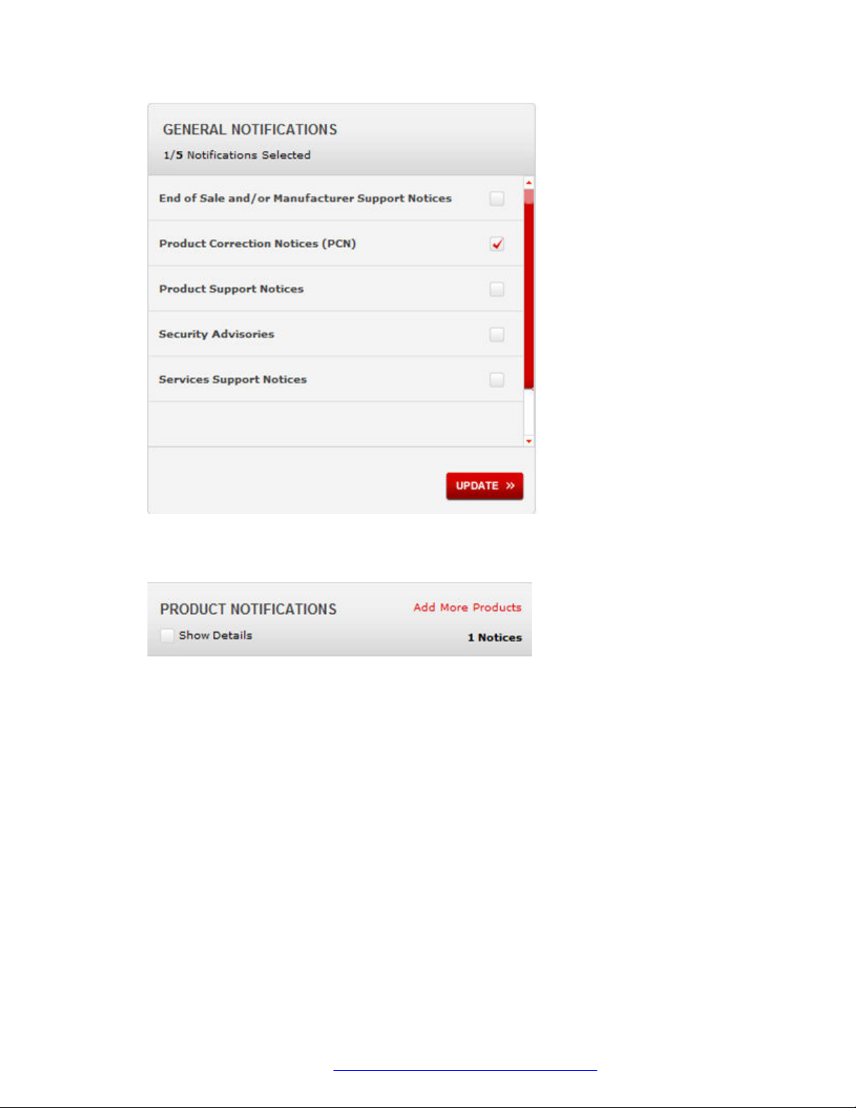
5. In the GENERAL NOTIFICATIONS area, select the required documentation types, and then
click UPDATE.
https://support.avaya.com.
February 2016 Installing Avaya Ethernet Routing Switch 4900 Series 6
Comments on this document? [email protected]
Page 7
Related resources
6. Click OK.
7. In the PRODUCT NOTIFICATIONS area, click Add More Products.
8. Scroll through the list, and then select the product name.
9. Select a release version.
10. Select the check box next to the required documentation types.
February 2016 Installing Avaya Ethernet Routing Switch 4900 Series 7
Comments on this document? [email protected]
Page 8

Introduction
11. Click Submit.
Support
Go to the Avaya Support website at http://support.avaya.com for the most up-to-date
documentation, product notices, and knowledge articles. You can also search for release notes,
downloads, and resolutions to issues. Use the online service request system to create a service
request. Chat with live agents to get answers to questions, or request an agent to connect you to a
support team if an issue requires additional expertise.
February 2016 Installing Avaya Ethernet Routing Switch 4900 Series 8
Comments on this document? [email protected]
Page 9

Chapter 2: New in this document
Installing Avaya Ethernet Routing Switch 4900 Series, NN47212-301 is a new document for 7.1 so
all the features are new in this release. See Release Notes for Avaya Ethernet Routing Switch 4900
and 5900 Series for a full list of features.
February 2016 Installing Avaya Ethernet Routing Switch 4900 Series 9
Comments on this document? [email protected]
Page 10
Chapter 3: Preinstallation checklist
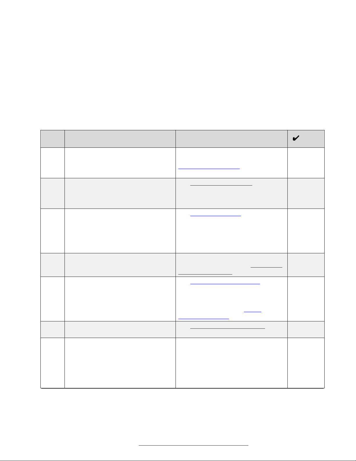
Before you install the Ethernet Routing Switch 4900 Series, make sure that you complete the tasks
in the preinstallation checklist.
No. Task Description
1. Review the technical specification for the
switch. Make sure that the area where
you install the switch and where it will
operate meet the requirements.
2. Verify the power supply unit (PSU)
specifications. Optionally order a
redundant PSU to provide redundancy
and load sharing.
3. Make sure that you have the following
tools and cables:
• Phillips #2 screwdriver RJ-45 console
port cable
• ESD cable
4. Unpack the equipment. Observe ESD precautions when you
5. Verify the contents of the shipped
package.
6. Make sure that the power cord has the
correct country-specific termination.
7. Prepare the rack. Ensure that there is enough rack space
For the physical, electrical, and
environmental specifications, see
Technical specifications on page 16.
See AC power specifications on
page 17.
See Cable requirements on page 25.
unpack the equipment. See Electrostatic
discharge prevention on page 15.
See Verifying package contents on
page 22 for a description of the
components that are provided with the
switch. If any components are missing,
contact Avaya support at https://
support.avaya.com/.
See AC power cord specifications on
page 20.
of 1.75 inches (4.45 centimeters).
Ensure that the rack is bolted to the floor
and braced if necessary.
Ensure that the rack is grounded to the
same grounding electrode used by the
Table continues…
February 2016 Installing Avaya Ethernet Routing Switch 4900 Series 10
Comments on this document? [email protected]
Page 11

No. Task Description
power service in the area. The ground
path must be permanent and must not
exceed 1 Ohm of resistance from the
rack to the grounding electrode.
See Installing the switch in an equipment
rack on page 26.
February 2016 Installing Avaya Ethernet Routing Switch 4900 Series 11
Comments on this document? [email protected]
Page 12
Chapter 4: Installing Ethernet Routing
Switch 4900 Series
This chapter provides the information and procedures to install the Ethernet Routing Switch 4900
Series.
Installation checklist
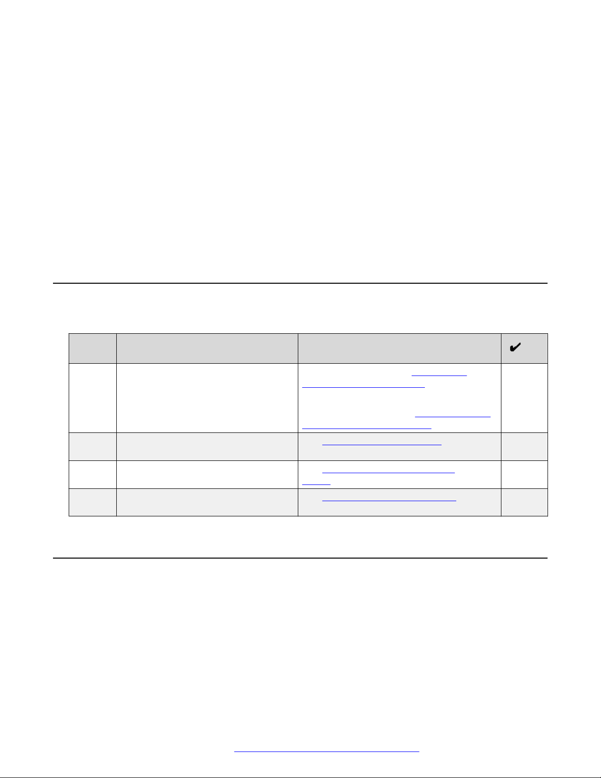
Use this checklist to install the Ethernet Routing Switch 4900 Series.
No. Task Description
1. Mount the Ethernet Routing Switch
4900 Series in the equipment rack.
3. Check the LEDs to verify the
installation.
2. (Optional) Install the secondary power
supply.
4. (Optional) Connect the switches in a
stack.
To install the switch, see Installing the
Switch in an equipment rack on page 26.
To install the switch using optional four-post
rack-mount brackets, see Installing optional
four post rack mount brackets on page 30.
See Switch LED state indicators on
page 50
See Installing the secondary power
supply on page 34
See Connecting switches in a stack on
page 46
Ethernet Routing Switch 4900 Series models
This section provides information about the switches in Ethernet Routing Switch 4900 Series.
Ethernet Routing Switch 4900 Series models
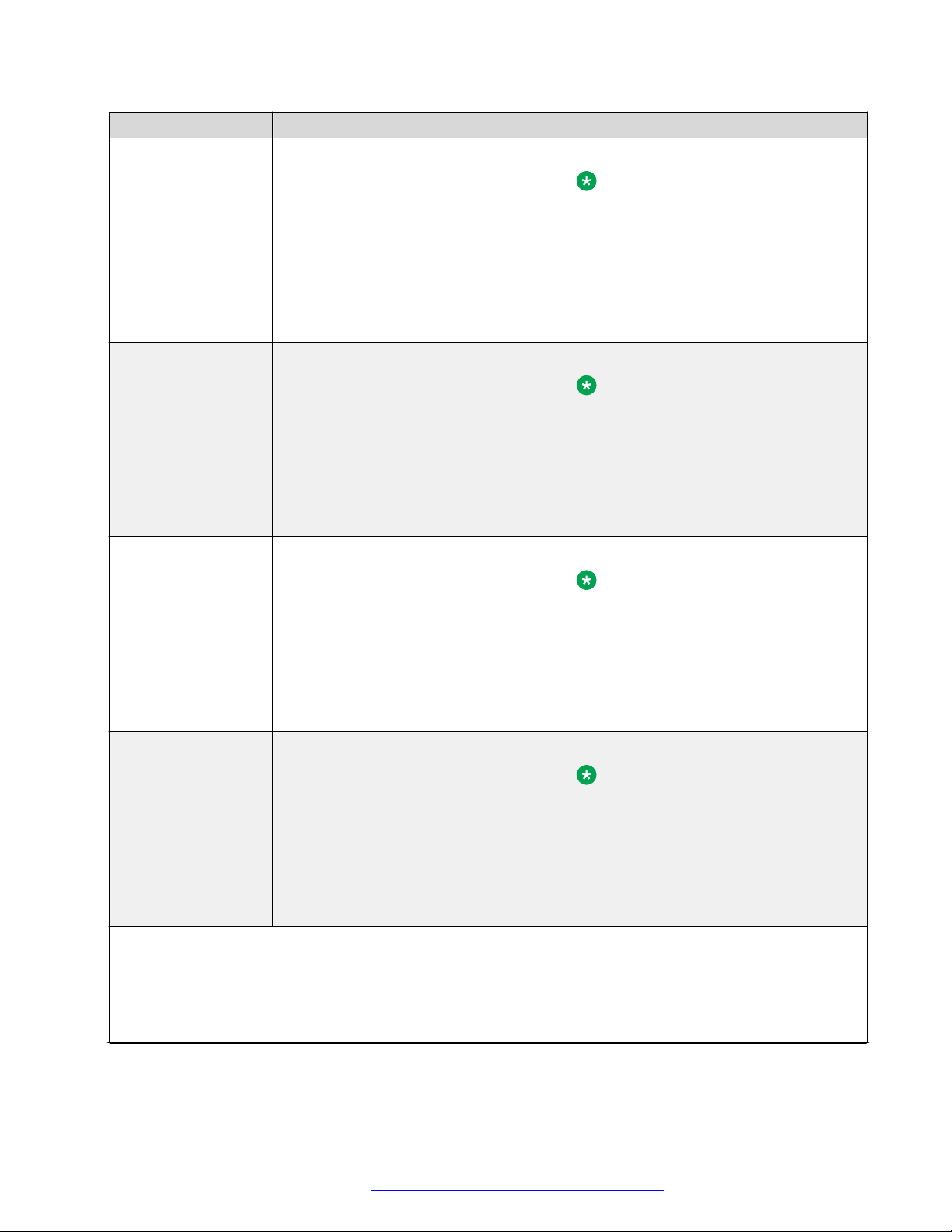
The following table lists the different Ethernet Routing Switch 4900 Series models and the key
features for each switch.
February 2016 Installing Avaya Ethernet Routing Switch 4900 Series 12
Comments on this document? [email protected]
Page 13
Ethernet Routing Switch 4900 Series models
Switch Model Key features Part Number
Ethernet Routing
Switch 4926GTS
• 24 ports, 10/100/1000 Base-T Ethernet
with two ports of SFP+ (10 Gbps)
interfaces
• Stackable Ethernet switch
AL4900x01-E6
Note:
Replace the “x” with a countryspecific power cord code. See the
• Non-PoE
footnote for details.
• Supports two modular 250 W Power
Supply Units (PSU), where one PSU is
required for operation and the optional
second is redundant
Ethernet Routing
Switch 4926GTSPWR+
24 ports 10/100/1000BaseT
Stackable Ethernet switch
PoE
1 rack unit high
AL4900x02-E6
Note:
Replace the “x” with a countryspecific power cord code. See the
footnote for details.
Uses modular power supply units and
has two field-serviceable power supply
receptacles, which support 250 W AC
power supply modules
Ethernet Routing
Switch 4950GTS
48 ports 10/100/1000BaseT
Stackable Ethernet switch
Non-PoE
1 rack unit high
AL4900x03-E61
Note:
Replace the “x” with a countryspecific power cord code. See the
footnote for details.
Uses modular power supply units and
has two field-serviceable power supply
receptacles, which support 1025 W AC
power supply modules
Ethernet Routing
Switch 4950GTSPWR+
48 ports 10/100/1000BaseT
Stackable Ethernet switch
PoE
1 rack unit high
AL4900x04-E6
Note:
Replace the “x” with a countryspecific power cord code. See the
footnote for details.
Uses modular power supply units and
has two field-serviceable power supply
receptacles, which support 1025 W AC
power supply modules
*Note: The character (x) in the order number indicates the power cord code. Replace the “x” with the proper
letter to indicate desired product nationalization. See the following for details:
“A”: No power cord included.
“B”: Includes European “Schuko” power cord common in Austria, Belgium, Finland, France, Germany, The
Netherlands, Norway, and Sweden.
Table continues…
February 2016 Installing Avaya Ethernet Routing Switch 4900 Series 13
Comments on this document? [email protected]
Page 14

Installing Ethernet Routing Switch 4900 Series
Switch Model Key features Part Number
“C”: Includes power cord commonly used in the United Kingdom and Ireland.
“D”: Includes power cord commonly used in Japan.
“E”: Includes North American power cord.
“F”: Includes Australian power cord.
Depending on the switch model, a 250 W or 1025 W PSU and .5 m stacking cable is provided for all
switches.
Common hardware features
The following hardware features are part of all switches in ERS 4900 Series:
• Standard ERS 19 inch rack mount hole pattern allowing horizontal or vertical, flush or offset,
front or rear mount options
• Front panel:
- one serial console connection
- one USB 2.1 Type A port
- status LED display panel
The following figure illustrates ERS 4900 Series front panel.
1. 10/100/1000 Ports (LEDs above the ports)
2. USB Type-A port
3. Reset push button
4. Status LEDs
5. SFP+ ports
6. Serial console port
Figure 1: Front panel
• Rear panel:
- two stack connectors
- one Base Select switch
- ports
February 2016 Installing Avaya Ethernet Routing Switch 4900 Series 14
Comments on this document? [email protected]
Page 15
Electrostatic discharge prevention
Note:
The port labeled AUX is disabled.
- power supply units
- one Kensington Lock slot located on the left side, near the back end of the chassis
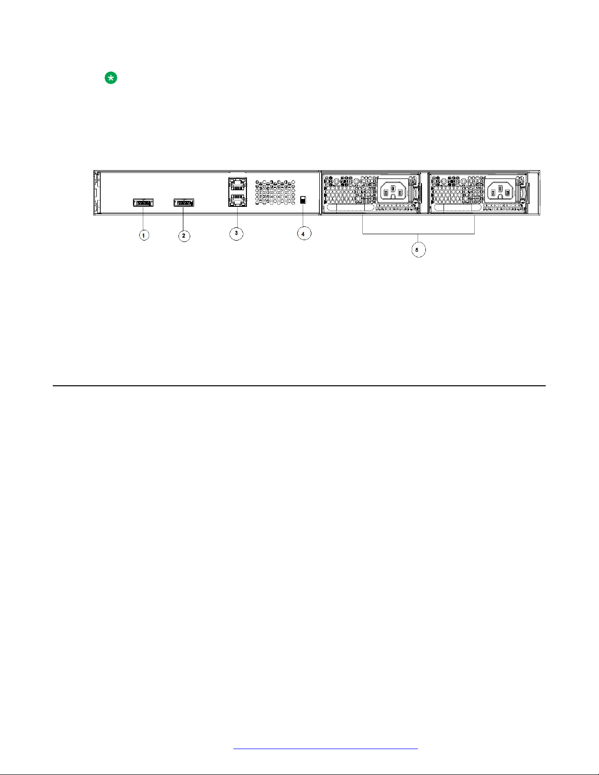
The following figure illustrates ERS 4900 Series rear panel.
1. Stack up connector
2. Stack down connector
3. Ports
4. Base Select Switch
5. Power Supply Units
Figure 2: Rear panel
Electrostatic discharge prevention
This module provides information and procedures for the prevention of electrostatic discharge
during the installation process.
Electrostatic discharge (ESD) is a discharge of stored static electricity that can damage equipment
and impair electrical circuitry. These electrostatic voltages can result from friction, including, but not
exclusive to, pulling cabling through conduits, walking across carpeted areas, and building up of
static charge in clothing. ESD damage occurs when electronic components are improperly handled
and can result in complete or intermittent failures. While networking equipment is commonly
designed and tested to withstand common mode ESD events, voltage sometimes can be
discharged to some connector pins but not others, or to some pins before others, which has the
potential to damage the networking equipment.
To protect the Avaya Ethernet Routing Switch against ESD damage, take the following preventive
measures before connecting any data cables to the device:
• Always use antistatic wrist straps. Make sure the strap is adjusted to provide good skin contact.
• Ensure that work surfaces and equipment racks are properly grounded for protection against
electrostatic discharge. The common point must be connected to the building ground wire. In a
properly wired building, the nearest reliable ground is typically at the electrical outlet.
• Avoid contact between equipment and clothing. The wrist or ankle strap only protects the
equipment from ESD voltages on the body; ESD voltages on clothing can still cause damage.
February 2016 Installing Avaya Ethernet Routing Switch 4900 Series 15
Comments on this document? [email protected]
Page 16

Installing Ethernet Routing Switch 4900 Series
• Avoid touching any connector pins.
• Do not remove the wrist or ankle strap until the installation is complete.
With new cable installations, Avaya recommends that the use of an ESD discharge cable to reduce
the potential for damage from static that can build up in cables. See the following figure.
Figure 3: ESD cable
Technical specifications
The following table provides the technical specifications for the switches in this series. Ensure that
the area where you install the switch and where it operates meets these requirements.
Warning:
To avoid bodily injury from hazardous electrical shock and current, never remove the top of the
device. No user-serviceable components are inside.
Table 1: Physical specifications
Height 4.4 cm – 1RU
Width 17.32 inch (440 mm or 44 cm) - 19 inch rack
mountable
Depth 18.89 inch (480 mm or 48 cm)
Weight (switch weight with one PSU. Where, PSU
approximately weighs 1.6 kg)
• ERS4926GTS: 7.2 kg
• ERS4926GTS-PWR+: 7.9 kg
• ERS4950GTS: 7.3 kg
• ERS4950GTS-PWR+: 8.0 kg
February 2016 Installing Avaya Ethernet Routing Switch 4900 Series 16
Comments on this document? [email protected]
Page 17
Technical specifications
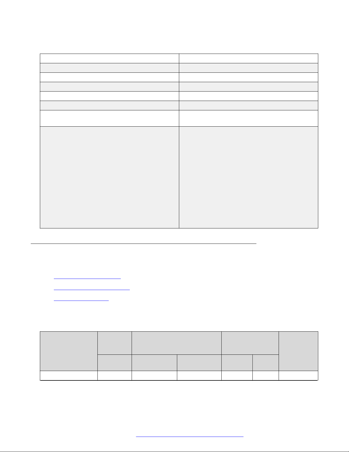
Table 2: Environmental specifications
Operating Temperature 0° and 50° C (32° and 106° F)
Storage Temperature –40°C to 85°C (-40°F to 185°F)
Operating Humidity 0 to 95 percent non-condensing
Storage Humidity 0 to 95 percent non-condensing
Maximum Operating Altitude 3,048 m (10,000 feet) above sea level
Storage Altitude 0 to 12,192 m (0 to 40,000 feet) above sea level
Acoustic Noise At 25°C Ambient Temperature, less than 48 dBA
typical, at 50°C, less than 61 dBA.
Miscellaneous Operating Considerations • No nearby heat sources such as hot air vents or
direct sunlight
• No nearby sources of severe electromagnetic
noise
• No excessive dust
• Adequate power source within six feet; one circuit
required for each power supply (see table, AC
power specifications)
• At least 2 inches (5.08 cm) on each side of the
switch unit for ventilation
• Cables should be dressed to prevent blocking air
flow.
Power specifications
This section provides the following power specifications for the switch:
• AC power specifications on page 17
• Typical power consumption on page 18
• PoE+ specifications on page 19
The following table describes the AC power specifications.
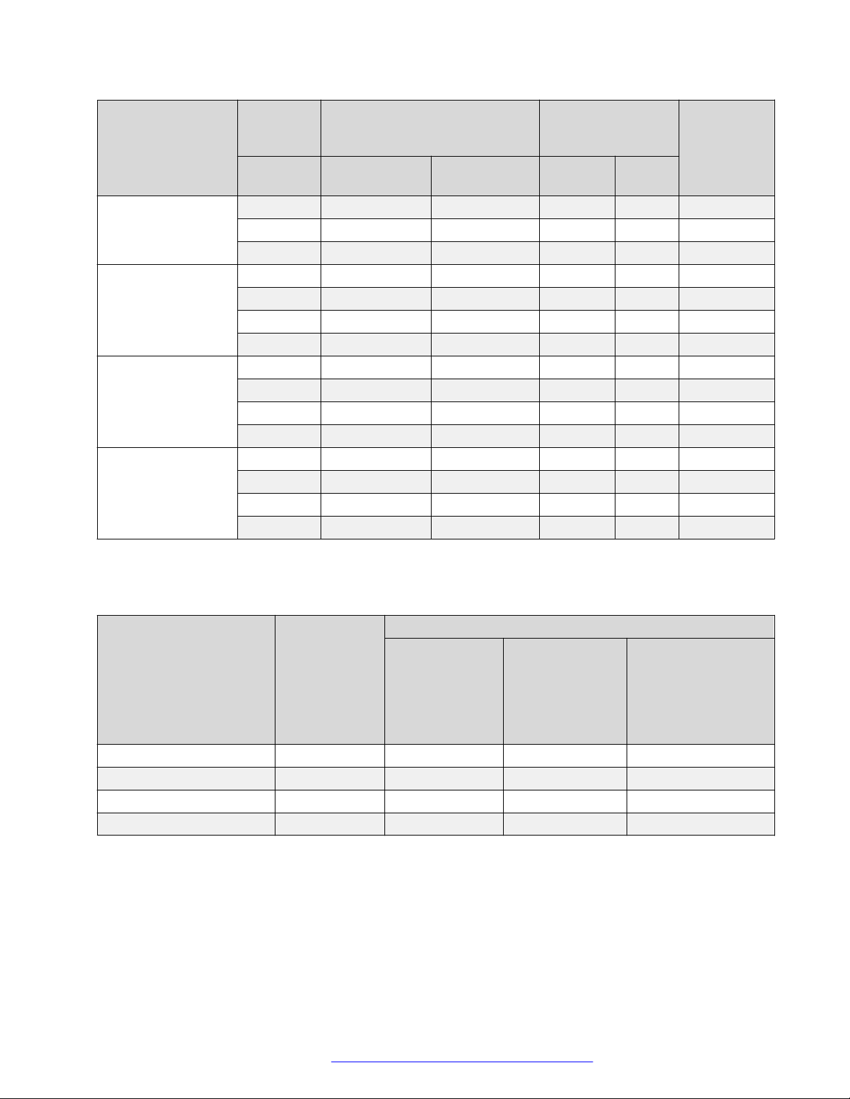
Table 3: AC power specifications
Model Number of
Power
supplies
Rated Line voltage Watts
ERS 4950GTS 1 250 W 200–240 VAC 53.14 0.30 181.31
Power supply Input power
(margined by 10%)
Amps
(Total)
Thermal
rating
(BTUs/hr
maximum)
Table continues…
February 2016 Installing Avaya Ethernet Routing Switch 4900 Series 17
Comments on this document? [email protected]
Page 18
Installing Ethernet Routing Switch 4900 Series
Model Number of
Power
supplies
Rated Line voltage Watts
2 250 W/PSU 200–240 VAC 58.88 0.44 200.89
1 250 W 100–110 VAC 53.67 0.51 183.12
2 250 W/PSU 100–110 VAC 59.53 0.58 203.11
ERS 4926GTS 1 250 W 200–240 VAC 39.37 0.25 134.33
2 250 W/PSU 200–240 VAC 46.23 0.40 157.73
1 250 W 100–110 VAC 39.43 0.38 134.53
2 250 W/PSU 100–110 VAC 44.35 0.46 151.32
ERS 4950GTSPWR+
ERS 4926GTSPWR+
1 1025 W 200–240 VAC 820.89 3.80 358.90
2 1025 W 200–240 VAC 1586.25 7.15 584.30
1 1025 W 100–110 VAC 842.10 7.75 431.95
2 1025 W 100–110 VAC 1660.07 15.15 837.88
1 1025 W 200–240 VAC 792.53 3.57 308.88
2 1025 W 200–240 VAC 816.03 3.78 342.32
1 1025 W 100–110 VAC 825.11 7.55 413.56
2 1025 W 100–110 VAC 839.64 7.73 424.24
Power supply Input power
(margined by 10%)
Amps
(Total)
Thermal
rating
(BTUs/hr
maximum)
The following table provides typical power consumption.
Table 4: Typical power consumption
Model Idle Power
consumption
(Watts)
ERS 4950GTS 43.9 53.0 NA 44.0
ERS 4926GTS 34.9 40.0 NA 34.9
ERS 4950GTS-PWR+ 65.9 73.4 382.0 65.9
ERS 4926GTS-PWR+ 51.4 55.8 208.8 51.5
Devices
connected to all
ports, typical
traffic, without
SFPs
Typical Power consumption (Watts)
Devices
connected to all
ports, typical
traffic, 6 W
average per PoE
device
With Avaya Energy
Saver enabled (PoE
Saver disabled on
PoE models)
The following table describes the Power over Ethernet (PoE+) specifications.
February 2016 Installing Avaya Ethernet Routing Switch 4900 Series 18
Comments on this document? [email protected]
Page 19

Table 5: PoE+ specifications
Technical specifications
Model Number of
Power Supplies
ERS 4950GTSPWR+
ERS 4926GTSPWR+
1 1025 W 200–240 VAC 30 W 720 W 24 ports
2 1025 W 200–240 VAC 30 W 1440 W 48 ports
1 1025 W 100–110 VAC 30 W 720 W 24 ports
2 1025 W 100–110 VAC 30 W 1440 W 48 ports
1 1025 W 200–240 VAC 30 W 720 W 24 ports
2 1025 W 200–240 VAC 30 W 720 W 24 ports
1 1025 W 100–110 VAC 30 W 720 W 24 ports
2 1025 W 100–110 VAC 30 W 720 W 24 ports
Power supply Power over Ethernet (PoE+)
power output
Rated Line voltage Max
Power
per Port
(Watts)
Max power
output
Sum of all Ports
(Watts)
at 30 W
at 30 W
at 30 W
at 30 W
at 30 W
at 30 W
at 30 W
at 30 W
MTBF values
The following table lists the MTBF values for the switches in ERS 4900 Series in combination with
one or two PSUs.
Model Number of PSUs Power Supply rating MTBF (hours)
4926GTS 1 250W 212,509
2 250W 191,705
4926GTS-PWR+ 1 1025W 211,044
2 1025W 197,295
4950GTS 1 250W 199,834
2 250W 181,329
4950GTS-PWR+ 1 1025W 195,578
2 1025W 183,714
February 2016 Installing Avaya Ethernet Routing Switch 4900 Series 19
Comments on this document? [email protected]
Page 20

Installing Ethernet Routing Switch 4900 Series
AC power cord specifications
The following section outlines the AC power cord specifications for various countries. Ensure that
you use the correct cord for your location.
Table 6: International power cord specifications
Country / Plug Specification Specifications Typical Plug
Continental Europe:
• 220 or 230 VAC
• CEE7 standard VII male plug
• Harmonized cord (HAR marking on the
outside of the cord jacket to comply with
the CENELEC Harmonized Document
HD-21)
United States of America / Canada / Japan:
• NEMA5-15P male plug
• UL-recognized (UL stamped on cord
jacket)
• CSA-certified (CSA label secured to the
cord)
United Kingdom:
• BS1363 male plug with fuse
• Harmonized cord
• 50 Hz
• Single Phase
• 100 or 120 VAC
• 50 - 60 Hz
• Single Phase
• 240 VAC
• 50 Hz
• Single Phase
Australia:
• AS3112-1981 male plug
February 2016 Installing Avaya Ethernet Routing Switch 4900 Series 20
Comments on this document? [email protected]
• 240 VAC
• 50 Hz
• Single Phase
Page 21

Universal Serial Bus ports
Universal Serial Bus ports
The switches feature a Universal Serial Bus (USB) port on the front panel. Switch administrators can
use the USB port to perform tasks, previously performed through Trivial File Transfer Protocol
(TFTP), with a USB Mass Storage Device (for example, a flash drive or thumb drive):
• download software
• generate and download the ASCII configuration file
• generate and download the binary configuration file
The storage capacity of the USB device in use limits file and system operations.
Support is available only for USB drives that comply with the Mass Storage subsection of the USB
1.1 and USB 2.0 specification. Support does not extend to third-party devices that do not comply
with these standards. Off-the-shelf drives that do not comply with these standards cannot operate
with the switch. Only FAT or FAT32 file systems are currently supported; USB drives with NTFS file
systems are not supported. Consult the documentation provided with the USB drive to ensure
compliance with these standards.
Connector pin assignments
The following section describes the connector pin assignments.
RJ-45 connector pin assignments for PoE switches
The following table describes the Power over Ethernet, and Power over Ethernet Plus RJ-45
connector pin assignments in ERS 4950GTS-PWR+ andERS 4926GTS-PWR+.
Table 7: PWR+ RJ-45 connector pin assignments
Connector Pin Number Signal Description
1 RX+/power– Receive Data+/power–
2 RX–/power– Receive Data–/power–
3 TX+/power+ Transmit Data+/power+
4 Not applicable Not applicable
5 Not applicable Not applicable
6 TX–/power+ Transmit Data–/power+
7 Not applicable Not applicable
8 Not applicable Not applicable
February 2016 Installing Avaya Ethernet Routing Switch 4900 Series 21
Comments on this document? [email protected]
Page 22

Installing Ethernet Routing Switch 4900 Series
Console port pin assignments
The following table describes the console port pin assignments.
Table 8: RJ–45 Console port pin assignments
Connector Pin Number Signal
1 Ready to send (RTS) — optional
2 Data terminal ready (DTR) — optional, can swap or link with pin
8
3 Transmit data (TXD) — mandatory
4 Carrier detect (DCD) — optional
5 Ground (GND) — mandatory
6 Receive data (RXD) — mandatory
7 Data set ready (DSR) — optional
8 Clear to send (CTS) — optional, can swap or link with pin 1
Equipment requirement
After unpacking this switch, check the contents to be that sure you have received all the
components. Then, before beginning the installation, be sure that you have all other necessary
installation equipment.
Verifying the package contents
For each Ethernet Routing Switch 4900 Series, verify the package contents with the items in the
following figure to ensure you have received all components. If any components are missing,
contact the vendor where you purchased the switch.
February 2016 Installing Avaya Ethernet Routing Switch 4900 Series 22
Comments on this document? [email protected]
Page 23

Table 9: Package contents
Item description Image
Avaya Ethernet Routing Switch
Equipment requirement
Rack-mounting hardware
Country-specific AC power cord
Note:
A power cord is not included
for the A variant of the switch.
Stacking cable 0.5 m
1. Rack mount brackets — Quantity: 2
2. M4 (8.5 mm) flat head screws — Quantity: 8
For information, see AC power cord specifications on page 20.
Table continues…
February 2016 Installing Avaya Ethernet Routing Switch 4900 Series 23
Comments on this document? [email protected]
Page 24

Installing Ethernet Routing Switch 4900 Series
Item description Image
One field replaceable power
supply module (two power supplies
are supported for models)
Documentation including the Quick
Install poster and Regulatory
document
Base Software License Kit
Optional rack-mounting equipment
If you plan to rack-mount the switch, ensure the following equipment is available:
Table 10: Optional equipment
Optional equipment Order code Equipment
Spare Rack Mount
Kit—used as a
replacement rack
mount kit.
19 inch Rack Mount
kit
700512595
Power Supply Unit specifications
The following table lists the order codes for optional Power Supply Units (PSU).
Table 11: PSU specifications
Switch Model Primary PSU Optional Secondary PSU
ERS 4950GTS, ERS 4926GTS 250W AC power supply 250W AC Power Supply
(order code: AL1905?09-E6)
Table continues…
February 2016 Installing Avaya Ethernet Routing Switch 4900 Series 24
Comments on this document? [email protected]
Page 25

Equipment requirement
Switch Model Primary PSU Optional Secondary PSU
(replacement order code:
AL1905?09-E6)
ERS 4950GTS-PWR+, ERS
4926GTS-PWR+
1025W AC POE+ power supply
(replacement order code:
AL1905?19-E6)
1025W AC power supply
(order code: AL1905?19-E6)
Cable requirements
The following table describes the cables required for Ethernet Routing Switch 4900 Series.
Table 12: Stacking cables
Description Material code
Stacking cable 0.5 m 700511668
Stacking cable 1.5 m 700511669
Stacking cable 3.0 m 700511670
Stacking cable 5.0 m 700511671
Console Port Adapters
The following cables are used for installing the switch into a network.
Table 13: Console port adaptors
Name Short Description Material code
Avaya RJ-45/DB-9 Console Cable 1.5m cable with DB-9 Female for
terminal/PC on one end and RJ-45
for device console port
connectivity on the other.
Avaya Blue DB-9 Male to RJ-45
Console Connector
Avaya Red DB-9 Female to RJ-45
Adaptor
Converts DB-9 of AL2011013-E6
console cable to RJ-45, a
Category 5 RJ-45 straight cable
can then connect to RJ-45 console
port.
Converts DB-9 MALE to RJ-45
serial port. The adaptor can be
used for PC or device with DB-9
MALE console port. Also, can be
used with Category 5 RJ-45
straight cable to provide console
connection.
AL2011022-E6
AL2011021-E6
AL2011020-E6
February 2016 Installing Avaya Ethernet Routing Switch 4900 Series 25
Comments on this document? [email protected]
Page 26

Installing Ethernet Routing Switch 4900 Series
Switch installation
This section describes how to install the switch in an equipment rack.
Installing the switch in an equipment rack
You can install the switch by mounting them at front or rear positions.
Caution:
When you mount the device in a rack, do not stack units directly on top of one another. You
must secure each unit to the rack with the appropriate mounting brackets. Mounting brackets
cannot support multiple units. For a translation of this statement, see Translations and Safety
messages on page 53.
Note:
Your switch might appear different than the following example figures. The instructions in this
section apply to all switches in Ethernet Routing Switch 4900 Series.
About this task
Install the switch in an equipment rack using the supplied brackets. The brackets secure the chassis
and prevent it from sliding around during vibration or when inserting or extracting transceivers.
Before you begin
• Ensure that you have a space of 1.75 inches (4.45 centimeters) in height for each switch in an
EIA or IEC-standard 19-inch (48.2-centimeter) equipment rack.
• The rack is bolted to the floor and braced if necessary.
• The rack is grounded to the same grounding electrode used by the power service in the area.
The ground path must be permanent and must not exceed 1 Ohm of resistance from the rack
to the grounding electrode.
Note:
Avaya does not supply the bolts used to secure the switch to the rack. Ensure you obtain the
appropriate bolts to secure the switch to your specific rack before you begin.
Caution:
When you mount the device in a rack, do not stack units directly on top of one another. You
must secure each unit to the rack with the appropriate mounting brackets. Mounting brackets
cannot support multiple units. For a translation of this statement, see Translation of safety
messages on page 53.
Procedure
1. Ensure power is disconnected from the switch.
2. Attach a bracket to each side of the switch with the included screws.
Attach the brackets in the best position for your specific equipment rack.
February 2016 Installing Avaya Ethernet Routing Switch 4900 Series 26
Comments on this document? [email protected]
Page 27

Switch installation
Figure 4: Front-mounted rack bracket installation
February 2016 Installing Avaya Ethernet Routing Switch 4900 Series 27
Comments on this document? [email protected]
Page 28

Installing Ethernet Routing Switch 4900 Series
Figure 5: Rear-mounted rack bracket installation
3. Slide the switch into the rack.
4. Insert and tighten the rack mount screws.
February 2016 Installing Avaya Ethernet Routing Switch 4900 Series 28
Comments on this document? [email protected]
Page 29

Switch installation
Figure 6: Front-mounted rack installation
February 2016 Installing Avaya Ethernet Routing Switch 4900 Series 29
Comments on this document? [email protected]
Page 30

Installing Ethernet Routing Switch 4900 Series
Figure 7: Rear-mounted rack bracket installation
Installing optional four-post rack-mount brackets
Perform this procedure to assemble and install the four-post rack-mount bracket kit.
Before you begin
Ensure to check for the following:
• Four-post server rack-mount kit.
• Verify that you have all the screws and brackets to assemble and install the four-post rack
mount kit.
• Tools:
- Phillips screwdriver to attach brackets to the switch and the switch to the rack.
- Hex wrench to assemble and attach the optional four-post rack-mount brackets.
• Rack requirements:
- Space of 2.8 inches (7.1 centimeters) for each switch in an E1A or 1EC standard 19 inch
(48.2 centimeter) equipment rack and T1A 23 inch (58.5 centimeter) equipment rack.
February 2016 Installing Avaya Ethernet Routing Switch 4900 Series 30
Comments on this document? [email protected]
Page 31

Switch installation
- Appropriate rack space to accommodate 1U switch height is 1.7 inches (44 millimeters).
- Four-post rack bolted to floor and braced if necessary.
- Four post-rack must be grounded to the same grounding electrode used by the power
service in the area. The ground path must be permanent and must not exceed 1 ohm of
resistance from the rack to the grounding electrode.
Figure 8: Four-post rack-mount kit assembly
Procedure
1. Attach a front bracket to each guide bracket with four 8.5 mm length flat head machine
screws.
2. Attach the guide brackets to the switch chassis.
February 2016 Installing Avaya Ethernet Routing Switch 4900 Series 31
Comments on this document? [email protected]
Page 32

Installing Ethernet Routing Switch 4900 Series
a. Use four M4 x 5.5 mm undercut flat-head hex machine screws to attach the rear of each
guide bracket to the switch chassis.
b. Verify that the rear screws sit flush in the guide brackets.
February 2016 Installing Avaya Ethernet Routing Switch 4900 Series 32
Comments on this document? [email protected]
Page 33

Switch installation
c. Test fit the rear mounting brackets in the guide brackets and verify that the rear
brackets can slide in the channels. Remove the rear brackets.
3. Install the switch into the equipment rack, temporarily using only the front rack mounts and
screws.
Figure 9: Install switch in rack using front rack mounts
4. Attach the rear mounting brackets and secure the switch to the rear rack posts.
a. Slide a rear mounting bracket into each guide bracket channel until flush with the rear
rack posts.
b. Secure the rear mounting brackets to the switch chassis with the pan-head screws.
February 2016 Installing Avaya Ethernet Routing Switch 4900 Series 33
Comments on this document? [email protected]
Page 34

Installing Ethernet Routing Switch 4900 Series
Figure 10: Attach rear mounting brackets
You can proceed with the installation by connecting power and network connections to the
switch.
Installing the secondary power supply
About this task
Your switch supports a combination of two field replaceable power supplies. You can install a
secondary power supply to provide redundancy, and load sharing.
Before you begin
Verify switch compatibility with the power supply. For more information, see
specifications on page 22.
Electrostatic alert:
To prevent damage from electrostatic discharge, always wear an antistatic wrist strap connected to
an ESD jack when performing maintenance on a switch. Ensure that the wrist strap makes contact
with your skin.
Power Supply Unit
February 2016 Installing Avaya Ethernet Routing Switch 4900 Series 34
Comments on this document? [email protected]
Page 35

Procedure
1. Insert each power supply into a rear power supply slot.
If a blanking plate covers the required power-supply slot, remove the plate before inserting
the power supply.
2. Verify that each fan tray is fully seated in the slot and secure each fan tray with two thumb
screws.
Note:
The switch chassis can prevent an incorrect installation of a power supply. If you insert a
power supply upside down, it may not get inserted fully and the thumb screws will not
engage.
Connecting switch to AC power
About this task
Connect a switch to a power source.
Connecting a transceiver to the switch or switch stack
Before you begin
• Ensure to check AC power specifications for the switch. For more information, see AC power
specifications on page 17.
• Ensure to check the AC power cord for international use. You must use a power cord that is
approved for the receptacle type in your country. For more information, see
specifications on page 20.
AC power cord
Procedure
Connect the AC power cord to the back of the switch, then connect the cord to a power outlet.
Note:
ERS 4900 does not have a power switch. When you connect the AC power cord to a suitable
AC power outlet, the switch powers up immediately.
Next steps
Check the front-panel LEDs as the device is powered on to be sure the PWR LED is lit. If not, check
that the power cable is correctly plugged in.
See Checking Light Emitting Diode on the switch on page 49.
Connecting a transceiver to the switch or switch stack
The following sections describe small form factor pluggable (SFP) transceivers.
February 2016 Installing Avaya Ethernet Routing Switch 4900 Series 35
Comments on this document? [email protected]
Page 36

Installing Ethernet Routing Switch 4900 Series
Installing SFP transceivers
About this task
This procedure describes the steps used to install transceivers.
Procedure
1. Remove the transceiver from the protective packaging.
2. Verify that the transceiver is the correct model for the network configuration.
3. Grasp the transceiver between the thumb and forefinger.
4. Insert the transceiver into the proper module on the switch. Apply a light pressure to the
transceiver until it clicks and locks into position in the module.
5. Remove the dust cover from the transceiver optical bores.
Example
The following graphic shows an SFP transceiver.
February 2016 Installing Avaya Ethernet Routing Switch 4900 Series 36
Comments on this document? [email protected]
Page 37

Connecting a transceiver to the switch or switch stack
Removing of SFP transceivers
Remove SFP transceivers by performing this procedure.
1. Disconnect the network fiber cable from the transceiver.
2. Use the locking mechanism on the transceiver to release it. The locking mechanism varies
from model to model as illustrated below.
February 2016 Installing Avaya Ethernet Routing Switch 4900 Series 37
Comments on this document? [email protected]
Page 38

Installing Ethernet Routing Switch 4900 Series
3. Slide the transceiver from the module slot.
4. If the transceiver does not slide easily from the module slot, use a gentle side-to-side rocking
motion while firmly pulling the transceiver from the slot.
5. Attach a dust cover over the fiber-optic bores and store the transceiver in a safe place until
you need it.
Important:
Discard transceivers in accordance with the proper laws and regulations.
Supported optical devices
Use optical devices to achieve high-bit-rate communications and long transmission distances. The
following section describes the supported optical devices on the switches.
Important:
Avaya recommends that you use Avaya branded SFP and SFP+ transceivers as they undergo
extensive qualification and testing. Avaya is not responsible for any problems that arise from
using non-Avaya branded SFP and SFP+ transceivers.
Small form-factor pluggable (SFP) transceivers
SFPs are hot-swappable input and output enhancement components designed to allow gigabit
Ethernet ports to link with other gigabit Ethernet ports over various media types.
You can use various SFP (1 Gbps) and SFP+ (10 Gbps) to attain different line rates and reaches.
The following table describes the SFPs including the reach provided by various SFPs.
This table is informational only—not all Avaya Ethernet switching and routing products support all
the SFPs listed here.
For more information about SFP and SFP+ transceivers, including technical specifications and
installation instructions, see Installing Transceivers and Optical Components on Avaya Ethernet
Routing Switch 4900 and 5900 Series, NN47211-302.
Important:
The attainable cable length can vary depending on the quality of the fiber-optic cable used.
February 2016 Installing Avaya Ethernet Routing Switch 4900 Series 38
Comments on this document? [email protected]
Page 39

Connecting a transceiver to the switch or switch stack
Table 14: SFP transceivers
Model Description Part number
Important:
Avaya supports SFP transceivers with the following part numbers: AA1419013-E5, AA1419014-E5,
AA1419015-E5, and AA1419025-E5 to AA1419040-E5. However, Avaya strongly recommends using
the newer DDI versions of these SFP transceivers.
1000BASE-T SFP gigabit Ethernet, RJ-45 connector AA1419043-E6
1000BASE-SX SFP 850 nm LC connector AA1419013-E5** This transceiver
has reached end-of-sale (EOS).
For more information about EOS
transceivers, and recommended
replacements for your product,
Locating end of sale
see
notices on page 42.
1000BASE-SX SFP 850 nm MT-RJ connector AA1419014-E5** This transceiver
has reached end-of-sale (EOS).
For more information about EOS
transceivers, and recommended
replacements for your product,
Locating end of sale
see
notices on page 42.
1000BASE-LX SFP 1310 nm LC connector AA1419015-E5** This transceiver
has reached end-of-sale (EOS).
For more information about EOS
transceivers, and recommended
replacements for your product,
Locating end of sale
see
notices on page 42.
1000BASE-XD CWDM SFP From 1470 nm to 1610 nm LC
connector, up to 40 km
AA1419025-E5 to AA1419032E5** These transceivers have
reached end-of-sale (EOS). For
more information about EOS
transceivers, and recommended
replacements for your product,
Locating end of sale
see
notices on page 42.
1000BASE-ZX CWDM SFP From 1470 nm to 1610 nm LC
connector, up to 70 km
AA1419033-E5 to AA1419040E5** These transceivers have
reached end-of-sale (EOS). For
more information about EOS
transceivers, and recommended
replacements for your product,
Locating end of sale
see
notices on page 42.
Table continues…
February 2016 Installing Avaya Ethernet Routing Switch 4900 Series 39
Comments on this document? [email protected]
Page 40

Installing Ethernet Routing Switch 4900 Series
Model Description Part number
1000BASE-SX DDI SFP 850 nm, gigabit Ethernet, duplex
AA1419048-E6
LC connector
1000BASE-LX DDI SFP 1310 nm, gigabit Ethernet, duplex
LC connector
1000BASE-XD DDI SFP 1310 nm, gigabit Ethernet, duplex
LC connector
1000BASE-XD DDI SFP 1550 nm, gigabit Ethernet, duplex
LC connector
1000BASE-ZX DDI SFP 1550 nm, gigabit Ethernet, duplex
LC connector
1000BASE-XD DDI SFP gigabit Ethernet, duplex LC
connector
1000BASE–ZX DDI CWDM 70 km
SFP
gigabit Ethernet, duplex LC
connector
AA1419049-E6
AA1419050-E6*
* This transceiver has reached
end-of-sale (EOS). For more
information about EOS
transceivers, and recommended
replacements for your product,
Locating end of sale
see
notices on page 42.
AA1419051-E6*
* This transceiver has reached
end-of-sale (EOS). For more
information about EOS
transceivers, and recommended
replacements for your product,
Locating end of sale
see
notices on page 42.
AA1419052-E6*
* This transceiver has reached
end-of-sale (EOS). For more
information about EOS
transceivers, and recommended
replacements for your product,
Locating end of sale
see
notices on page 42.
AA1419053-E6 to AA1419060E6** These transceivers have
reached end-of-sale (EOS). For
more information about EOS
transceivers, and recommended
replacements for your product,
Locating end of sale
see
notices on page 42.
AA1419061-E6 to AA1419068E6** These transceivers have
reached end-of-sale (EOS). For
more information about EOS
transceivers, and recommended
replacements for your product,
Locating end of sale
see
notices on page 42.
Table continues…
February 2016 Installing Avaya Ethernet Routing Switch 4900 Series 40
Comments on this document? [email protected]
Page 41

Connecting a transceiver to the switch or switch stack
Model Description Part number
Important:
AA1419065–E6 remains
available for purchase.
1000BASE-BX10 DDI SFP 1310 nm (tx) and 1490 nm (rx)
gigabit Ethernet, single-fiber LC
connector
1000BASE-BX40 DDI SFP 1490 nm (tx) 1310 nm (rx)
gigabit Ethernet, single-fiber LC
connector
1000BASE-EX DDI SFP 1550 nm, gigabit Ethernet, duplex
LC connector
AA1419069-E6 (10 km at 1310
nm ) and mating pair AA1419070E6 (10 km at 1490 nm)
AA1419076-E6 (40 km at 1310
nm) and mating pair AA1419077E6 (40 km at 1490 nm)
AA1419071-E6** This transceiver
has reached end-of-sale (EOS).
For more information about EOS
transceivers, and recommended
replacements for your product,
Locating end of sale
see
notices on page 42.
Small form-factor pluggable plus (SFP+) transceivers
SFP+ transceivers are hot-swappable input and output enhancement components that allow 10
gigabit connections. All Avaya SFP+ transceivers use Lucent connectors (LC) to provide precision
keying and low interface losses.
The following table lists and describes the Avaya SFP+ models.
Table 15: Supported SFP+ transceivers and cables
Model
10GBASE-SR/SW SFP+ 400 m, 850 nm MMF AA1403015-E6
10GBASE-LRM SFP+ 220 m, 1260 to 1355 nm; 1310 nm
10GBASE-LR/LW SFP+ 10 km, 1310 nm SMF AA1403011-E6
10GBASE-ER/EW SFP+ 40 km, 1550 nm SMF AA1403013-E6
10GBASE-CX SFP+ 2-pair
twinaxial copper cable that plugs
into the SFP+ socket and
connects two 10-gigabit ports
10GBASE-CX SFP+ 2-pair
twinaxial copper cable that plugs
into the SFP+ socket and
connects two 10-gigabit ports
10GBASE-CX SFP+ 2-pair
twinaxial copper cable that plugs
Description Part number
AA1403017-E6
nominal MMF
10 meter AA1403018-E6
3 meter AA1403019-E6
5 meter AA1403020-E6
Table continues…
February 2016 Installing Avaya Ethernet Routing Switch 4900 Series 41
Comments on this document? [email protected]
Page 42

Installing Ethernet Routing Switch 4900 Series
Model Description Part number
into the SFP+ socket and
connects two 10-gigabit ports
10GBASE-ZR/ZW SFP+ 70 km, 1550 nm SMF AA1403016-E6
10GBASE-BX10 SFP+ 10 km AA1403169-E6 and AA1403170-
E6
Optical power considerations
When you connect the device to collocated equipment, ensure that enough optical attenuation exists
to avoid overloading the receivers of each device. You must consider the minimum attenuation
requirement based on the specifications of third-party equipment. For more information about
minimum insertion losses for Avaya optical products, see Installing Transceivers and Optical
Components on Avaya Ethernet Routing Switch 4900 and 5900 Series, NN47211-302.
Locating end of sale notices
Use the following procedure to locate the most up-to-date information on end of sale notices and
replacement recommendations for transceivers and optical components.
Procedure
1. Go to the Avaya Support website at
2. Select Support by Product > Documents.
3. Enter the product name, and a release.
4. Select Product Lifecycle Notices.
5. Click Enter.
6. Select the End of Sale notice to view the information.
http://support.avaya.com/.
Stacking
The switch provides fail-safe stackability. You can connect up to eight 4900 series devices in a stack
to provide uninterrupted connectivity for up to 400 ports. You can manage the stack as a single unit.
Stack connector
The stack connector is a component of the switch back panel and consists of the Unit Select switch,
Cascade Down connector, and Cascade Up connector. The stack connector is illustrated in the
following diagram.
February 2016 Installing Avaya Ethernet Routing Switch 4900 Series 42
Comments on this document? [email protected]
Page 43

Stacking
Figure 11: Stack Connector
Unit Select switch
Use the Unit Select switch to designate a switch in the stack as the base unit. Slide the Unit Select
switch DOWN to designate a switch as the base unit. You can designate only one switch in a stack
as the base unit; that is, with the switch in the base unit position. For all other switches in the stack,
the Unit Select switch must be positioned UP.
The base unit designation for a switch appears on the front panel LED display. See
Switch LED
state indicators on page 50.
Cascade Down connector
Use the Cascade Down connector to connect a switch to the next unit in the stack through a
cascade cable. Connect the other end of the Cascade Down cable to the Cascade Up connector of
the next switch in the stack. A return cable from the Cascade Down connector of another unit to the
Cascade Up connector of the first unit completes the stack connection.
Important:
To create a stack connection, order the appropriate switch cascade cables to ensure fail-safe
stacking. A 1.5 foot stacking cable is included with the switch. For stacking three or more units
(maximum eight units per stack), order the cables as applicable.
Cascade Up connector
The Cascade Up connector provides an attachment point that accepts a cascade cable connection
from another unit in the stack. A return cable from the Cascade Down connector of one switch to the
Cascade Up connector of an adjacent switch completes the stack connection. The following figure
illustrates a typical crossover connection configuration. Failure to use this configuration can result in
loss of connectivity.
Important:
In the Unit 1, set the Base unit select switch position to Base.
February 2016 Installing Avaya Ethernet Routing Switch 4900 Series 43
Comments on this document? [email protected]
Page 44

Installing Ethernet Routing Switch 4900 Series
1. Base Unit
2. Cascade Cable (connected from Base Unit Cascade Down connector to
Unit 2 Cascade Up connector)
3. Cascade Cable (connected from Unit 2 Cascade Down connector to Base
Unit Cascade Up Connector)
Initial installation unit number assignment
When you install the stack, the software automatically determines the physical order of all units in
the stack according to the position of the base unit within the stack. Thereafter, the individual units
maintain their original unit numbering, even if you change the position of one or more units in the
stack.
For example, when you initially power the stack, the base unit becomes unit 1 and the unit that the
base unit connects to (across the Cascade Down cable) becomes unit 2. The next unit is designated
as unit 3, this continues until the maximum stack configuration (up to eight units) is reached. If
another unit in the stack is designated as the base unit, the new base unit keeps its originally
designated unit number in the stack.
Stack MAC address
When a switch participates in a stack configuration, stack initialization automatically assigns a stack
MAC address. The stack MAC address is the base unit MAC address plus 1. If another unit in the
stack is assigned as the base unit, the new stack MAC address is the MAC address of the new base
unit plus 1. The original stack IP address still applies to the new base unit.
Temporary base unit
If an assigned base unit fails, the next unit in the stack order automatically becomes the new
temporary base unit. The LED display on the front panel of the temporary base unit changes to a
steady amber state to indicate the change. When this happens, use the Unit Select switch to
designate the temporary base unit as the base unit until you repair or replace the failed base unit.
You must designate a base unit because the automatic failover is only a temporary safeguard and, if
the original unit rejoins the stack, it does not resume base unit status. Also, if the stack configuration
loses power, the temporary base unit does not resume base unit status when power is restored.
Important:
If the temporary base unit is not assigned as the new base unit, and the temporary base unit
fails, the next unit in the stack order becomes the temporary base unit. This process continues
after successive failures until only two units are left in the stack.
February 2016 Installing Avaya Ethernet Routing Switch 4900 Series 44
Comments on this document? [email protected]
Page 45

Stacking
Redundant cascade stacking
You can stack up to eight units into a dual-path cascade stack. If any single unit fails, or if a cable is
accidently disconnected, other units in the stack remain operational.
In addition to increasing bandwidth, the software uses the cables to provide two paths between
units. If one path is interrupted, the data travels over the remaining path at half the normal interswitch bandwidth.
The following figure shows a typical example of a stack configuration reacting to a failed connection
in the stack configuration.
1. Base Unit
2. Last Unit
3. Unit selector switch
4. Cascade Cable
In the example, the following occur:
• Unit 3 becomes nonoperational due to a unit failure, cable disconnection, or a loss of power.
• Units 2 and 4, directly upstream and downstream from Unit 3, sense the loss of link signals
from unit 3. The software directs all the data to traverse the remaining path.
• The Cascade Down LED for Unit 2 and the Cascade Up LED for Unit 4 turn amber to indicate
an error.
• The remaining stack units remain connected and continue to operate.
February 2016 Installing Avaya Ethernet Routing Switch 4900 Series 45
Comments on this document? [email protected]
Page 46

Installing Ethernet Routing Switch 4900 Series
Connecting switches in a stack
About this task
Connect a switch to the next unit in the stack through a cascade cable. The stack parameters are
associated with the base unit, the physical stack order depends on the base unit position and
whether you configure the stack cascade up (stack up) or cascade down (stack down). This
designation depends on the stack cabling arrangement.
Note:
Avaya recommends that you use a Cascade Down configuration.
Before you begin
Order the appropriate Avaya Ethernet Routing Switch 4900 Series cascade cables to ensure failsafe stacking. For more information, see
Procedure
1. Ensure that all switches for the stack are rack mounted.
2. Slide the Unit Select switches on the back of the units to the appropriate position, depending
on whether they are a base unit or non-base unit:
Cable requirements on page 25.
• Base Unit (Unit 1)- Slide the Unit Select switch DOWN
• Non-Base Unit (Units 2-8)- Slide the Unit Select switch UP
Note:
The Base Unit Select switch defaults to be in the Non-Base position. Only one switch in
the stack must have the Base Unit Select switch set to the Base position.
3. Connect stacking cables as required for a Cascade Up (stack up) or Cascade Down (stack
down) configuration.
See Stack configurations on page 46 for cable connection reference.
Stack configurations
Stack parameters are associated with the base unit, the physical stack order depends on the base
unit position and whether you configure the stack cascade up (stack up) or cascade down (stack
down). The designation depends on the stack cabling arrangement.
Cascade down
In a cascade down configuration, the base unit is located at the top of the stack. The system
automatically numbers the physical units based on the designated base unit (unit 1). The cable
connected to the Cascade Down connector of the base unit terminates in the Cascade Up connector
on the next unit in the stack, which is located below the base unit. This next unit is designated unit 2.
The stack is wired downward through the units and the system continues to number in this manner
February 2016 Installing Avaya Ethernet Routing Switch 4900 Series 46
Comments on this document? [email protected]
Page 47

Stacking
throughout the stack. In this configuration, the base unit discovers the stack in a cascade down
(stack down) direction.
1. Base Unit
2. Last Unit
3. Cascade or Stack Cable
4. Cascade/Stack Cable (Return cable to make stack resilient. Use longer
Stack Cable if required)
Figure 12: Cascade Down (Stack Down) configuration
Cascade up
In a cascade up (stack up) configuration, the base unit is physically the bottom unit in the stack. The
cable connected to the Cascade Up connector of the base unit terminates in the Cascade Down
February 2016 Installing Avaya Ethernet Routing Switch 4900 Series 47
Comments on this document? [email protected]
Page 48

Installing Ethernet Routing Switch 4900 Series
connector of the last unit physically at the top of the stack. The stack is wired upward through the
units and the system continues to number in this manner throughout the stack. In this configuration,
the base unit discovers the stack in a cascade up (stack up) direction.
1. Base Unit
2. Last Unit
3. Cascade or Stack Cable
4. Cascade/Stack Cable (Return cable to make stack resilient. Use longer
Stack Cable if required)
Figure 13: Cascade Up (Stack Up) configuration
February 2016 Installing Avaya Ethernet Routing Switch 4900 Series 48
Comments on this document? [email protected]
Page 49

Checking Light Emitting Diode on the switch
Replacing or adding a stack unit
Use the following procedure to replace a failed stack unit or insert a new unit into a stack.
Important:
Automatic Unit Replacement (AUR) for both configuration and software is enabled for all switch
platforms and software releases. This means that the agent code image, on a replacement unit,
is automatically upgraded or downgraded to match the software running on the stack. In
addition, when a like-for-like replacement of a failed unit occurs, any port-specific configuration
is restored.
Procedure
1. Remove the failed switch from the stack.
2. Obtain a like-for-like replacement switch.
3. With the new unit turned off, physically insert the new unit in the stack and reconnect the
stack cables.
4. Turn on the new unit. Depending on the software load on the replacement switch, it can
automatically restart one or two times before joining the stack as a fully operational member.
5. Check the log file on the stack to ensure that the replacement unit correctly joined the stack.
The log file displays AUR information messages.
If you replace the base unit, remember that the stack has elected a temporary base unit and
the new unit does not automatically assume the base unit status. Configure the new unit as
the base unit, using the Unit Select switch, and reset the Unit Select switches of the other
stack members to nonbase units.
Removing a stack unit
If you remove a unit from the stack (to operate in standalone mode), the following switch
configuration settings revert to those configured before the unit became a member of the stack:
• IP address
• Web, Telnet, and SNMP passwords
• SNMP community strings
Checking Light Emitting Diode on the switch
The figures and tables in the following sections describe the LEDs on the switch. The tables
describe LED operation for a switch that finishes the power-on self-test.
February 2016 Installing Avaya Ethernet Routing Switch 4900 Series 49
Comments on this document? [email protected]
Page 50

Installing Ethernet Routing Switch 4900 Series
Switch LED state indicators
The following table describes the main switch LED state indications provided by LED color and
fluctuation cues.
Table 16: Switch LED state indicators
Label Color and Status Description
PWR Green (solid) The switch is receiving power either from the primary or
secondary power supply.
Off The switch is not receiving power and not operating.
Status Green (solid) • During start-up: The power-on self-test (POST) is complete
and the switch is operating normally.
• After start-up: The switch is running the agent code
successfully.
Green (blinking) The switch is loading the agent software code.
Amber (solid) The switch encountered an error when running the diagnostic
software. (See note)
Amber (blinking) The switch is booting and running diagnostic software. Normal
activity during boot process. (See note)
Off The switch failed the power-on self-test (POST) or failed to load
the agent code.
Up / Down Green (solid) The switch formed a neighbor with the adjacent switch over
Stack up/down cables.
Green (blinking) The switch formed a partial neighbor with the adjacent switch
over Stack up/down cables. Check the switch logs.
Amber (solid) The switch detects Stack up/down cables are present and
connected to an adjacent switch, but adjacency did not
complete. Check the switch logs.
Off No Stack up/down connection is present, or the switch is in
stand-alone mode.
Base Green (solid) The switch is operating as the base unit for the stack.
Green (blinking) The switch joined the stack and Automatic Unit Replacement is
running to upgrade the diagnostics, agent, or configuration file.
Amber (solid) The switch is operating as the temporary base unit for the stack.
Amber (blinking) Problem with election of a base unit for the stack. Either no
switch has the base unit switch on, or multiple units have the
base unit switch on.
Amber (fast flashing) The switch was not allowed to join the stack. Check the switch
logs.
Off The switch is not the base unit or temporary base unit, or the
switch is operating in stand-alone mode.
February 2016 Installing Avaya Ethernet Routing Switch 4900 Series 50
Comments on this document? [email protected]
Page 51

Checking Light Emitting Diode on the switch
Port LED state indicators
This section describes the port LED state indicators by color and fluctuation cues.
The following list describes the three port LEDs:
• Activity indicates the level of activity on the link.
• Link indicates the presence of an Ethernet link.
• Speed indicates the port speed (for example, 10 Mb/s, 100 Mb/s, 1000 Mb/s).
Table 17: RJ-45 Port LED state indicators
Label Color and Status Description
Speed/PoE Green, Pulse Green—
Green
Green, Steady The port is set to operate at 1000 Mb/s and no PoE power is
Amber, Pulse Amber—
Amber
Amber, Steady The port is set to operate at 1000 Mb/s and no PoE power is
Amber, Green Pulse The port is experiencing a PoE error.
Off When the Link/Activity LED is green and the Speed LED is off,
Link / Activity Green, Steady The link established but no data activity exists.
Green, Blink The link is established and data activity exists (the blink rate
Green, Slow Blink The software disabled the port.
Amber, Steady Port not used.
Amber, Blink Not applicable.
Off The port has no link or activity.
The port is set to operate at 1000 Mb/s and PoE is delivered on
the PoE model port.
delivered on the port, on non-PoE or PoE models without a
PoE consumer attached to the port.
The port is set to operate at 100 Mb/s and PoE is delivered on
the PoE model ports.
delivered on non-PoE switch ports or PoE switches without a
PoE consumer attached to the port.
the port is set to operate at 10 Mb/s.
indicates the level of activity).
Table 18: SFP transceiver Port LED state indicators
Label Color and Status Description
In Use Green, Blink Not applicable.
Green, Steady The SFP port and the transmit port are active.
Amber, Blink Not applicable.
Amber, Steady SFP Installed—TX Port Inactive
Table continues…
February 2016 Installing Avaya Ethernet Routing Switch 4900 Series 51
Comments on this document? [email protected]
Page 52

Installing Ethernet Routing Switch 4900 Series
Label Color and Status Description
Off No SFP transceiver is present.
Link / Activity Green, Blink Activity exists on the port.
Green, Slow Blink Software disabled this port.
Green, Steady The link is operating normally.
Off No link exists.
Table 19: SFP+ Port LED state indicators
Label Color and Status Description
TX / RX Green, Steady SFP+ detected and link established
Green, Flashing SFP+ established and transmit/receive activity detected.
Amber, Steady SFP detected and link established
Amber, Flashing SFP established and transmit/receive activity detected.
Amber, Blinking TX and RX blink together slowly to indicate a disabled port.
Off No SFP or SFP+ connection detected.
Note:
If you link two ports explicitly set for different speeds (for example one configured as 10BaseT
and the other as 100BaseTX) the port link LED may indicate a link, but the switch does not
establish a link. Connect ports using the same set speed or use auto-negotiation on each
switch.
February 2016 Installing Avaya Ethernet Routing Switch 4900 Series 52
Comments on this document? [email protected]
Page 53

Appendix A: Translations of safety
messages
This module contains translations of the safety messages found in the Ethernet Routing Switch
4900 Series documentation suite.
Safety messages
Caution:
When mounting this device in a rack, do not stack units directly on top of one another in the
rack. Each unit must be secured to the rack with appropriate mounting brackets. Mounting
brackets are not designed to support multiple units.
Important:
Achtung: Wenn diese Einheit in einem Rack montiert wird, muß ein gewisser Abstand zur
nächsten Einheit gelassen werden. Jede Einheit muß mit geeignetem Befestigungsmaterial
gesichert werden. Das Befestigungsmaterial ist nicht für die gleichzeitige Befestigung mehrerer
Einheiten geeignet.
Important:
Si vous installez le module dans une baie, ne l’empilez pas directement sur un autre. Chaque
module doit être fixé à sa propre baie à l’aide des supports de montage appropriés. Ces
supports ne sont pas conçus pour résister à plusieurs modules.
Important:
Precautión: Cuando monte este dispositivo en un bastidor, no apile las unidades directamente
una encima de otra. Cada unidad debe fijarse en el bastidor con las abrazaderas de montaje
adecuadas. Las abrazaderas de montaje no están diseñadas para sostener varias unidades.
Important:
Se il dispositivo viene installato in un rack, non impilare le unità direttamente una sull’altra. Ogni
unità deve essere fissata al rack con le staffe di montaggio appropriate. Le staffe di montaggio
non sono state progettate per supportare più unità.
February 2016 Installing Avaya Ethernet Routing Switch 4900 Series 53
Comments on this document? [email protected]
Page 54

Translations of safety messages
Caution:
If you are not installing a module in the slot, be sure to keep the metal cover plate in place over
the slot. Removing the cover plate impedes airflow and proper cooling of the unit.
Important:
Achtung: Wenn Sie kein Modul im Schacht verwenden, muß die Metallabdeckung über dem
Schacht montiert sein. Eine Entfernung der Abdeckung führt zu einer Verschlechterung der
Luftzirkulation und damit zu einer nicht ausreichenden Kühlung der Einheit.
Important:
Si vous n’installez pas le module dans une baie, veillez à laisser la plaque métallique sur la
baie. Si vous la retirez, l’aération du module ne peut pas s’effectuer correctement.
Important:
Precaution: Si no instala ningún módulo en la ranura, asegúrese de mantener la placa de la
cubierta de metal en la misma. Si la retira, impedirá que el aire circule y la unidad se refrigere
adecuadamente.
Important:
Attenzione: Se nello slot non vengono installati moduli, assicurarsi di mantenere la piastra di
copertura metallica in sede sopra lo slot. La rimozione della piastra impedisce la ventilazione e il
corretto raffreddamento dell’unità.
February 2016 Installing Avaya Ethernet Routing Switch 4900 Series 54
Comments on this document? [email protected]
Page 55

Safety messages
Warning:
Disconnecting the AC power cord is the only way to turn off AC power to this device. Always
connect the AC power cord in a location that can be reached quickly and safely in case of an
emergency.
Important:
Warnung: Das Gerät kann nur durch Ziehen des Netzsteckers ausgeschaltet werden.
Schließen Sie das Netzkabel an einer Steckdose an, die in Notfällen schnell und sicher
zugänglich ist.
Important:
Avertissement: Pour mettre le module hors tension, vous devez impérativement déconnecter
le cordon d’alimentation. En outre, vous devez dégager un espace minimal dans la zone de
câblage pour pouvoir y accéder facilement en cas d’urgence.
Important:
Advertencia: Para apagar el dispositivo debe desenchufar el cable. Conecte siempre el cable
de alimentación a una toma segura y de fácil acceso por si se produjera alguna situación de
emergencia.
Important:
Avviso: L’unico modo per disattivare questo dispositivo consiste nello scollegare il cavo di
alimentazione. Collegare sempre il cavo di alimentazione ad una presa che sia facilmente e
rapidamente accessibile in caso di emergenza.
Danger:
Use only power cords that have a grounding path. Without a proper ground, a person who
touches the switch is in danger of receiving an electrical shock. Lack of a grounding path to the
switch may result in excessive emissions.
February 2016 Installing Avaya Ethernet Routing Switch 4900 Series 55
Comments on this document? [email protected]
Page 56

Translations of safety messages
Important:
Vorsicht: Verwenden Sie nur Netzkabel mit Schutzerdung. Ohne ordnungsgemäße
Schutzerdung besteht für Personen, die den Switch berühren, die Gefahr eines elektrischen
Schlages. Eine nichtvorhandene Schutzerdung kann zu sehr starken Abstrahlungen führen.
Danger:
N’utilisez que des cordons d’alimentation équipés de trajet de mise à la terre. Sans mise à la
terre adaptée, vous risquez de recevoir une décharge électrique en touchant le commutateur.
Par ailleurs, l’absence de trajet de mise à la terre peut générer des émissions excessives.
Important:
Peligro: Utilice únicamente cables de alimentación con toma de tierra. De lo contrario, al tocar
el interruptor puede recibir una descarga eléctrica. Si no hay un circuito de toma de tierra en el
enchufe, puede producirse un exceso de emisiones.
Important:
Pericolo: Utilizzare esclusivamente cavi di alimentazione dotati di un percorso per la messa a
terra. Senza un’adeguata messa a terra, chiunque tocchi lo switch corre il rischio di ricevere una
scossa elettrica. L’assenza di un percorso per la messa a terra verso lo switch può comportare
un eccesso di emissioni.
February 2016 Installing Avaya Ethernet Routing Switch 4900 Series 56
Comments on this document? [email protected]
Page 57

Index
C
Console pin assignments .....................................................22
R
RJ-45 pin assignments ........................................................ 21
S
support ...................................................................................8
U
Universal Serial Bus (USB) ports .........................................21
USB ports ............................................................................ 21
V
videos .................................................................................... 5
February 2016 Installing Avaya Ethernet Routing Switch 4900 Series 57
Comments on this document? [email protected]
 Loading...