

Page 1
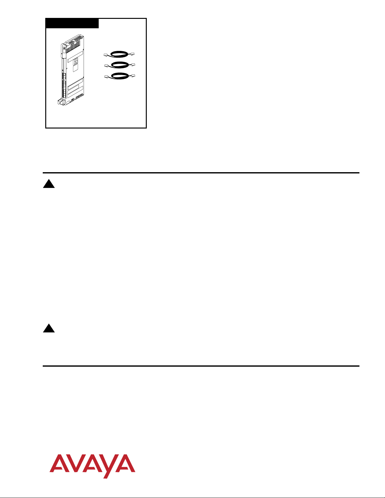
308EC Module
Expanding Your PARTNER® Advanced
Communications System
This document provides instructions for adding or replacing modules in
P
A
R
T
N
E
R
3
0
0
0
7-foot
Line Cords
308EC
Module
The instructions also apply to previous models of PARTNER, including the PARTNER, PARTNER PLUS,
and PARTNER II Communications Systems. Please note the illustrations are examples only. Your system
may look different.
Important Safety Instructions
!
WARNING:
The following list provides basic safety precautions that should always be followed when using your telephone
equipment:
1. Read and understand all instructions.
2. Follow all warnings and instructions marked on the equipment.
3. Unplug all telephone connections before cleaning. DO NOT use liquid cleaners or aerosol cleaners. Use a
damp cloth for cleaning.
4. The product should be serviced by (or taken to) a qualified repair center when service or repair work is
required.
5. DO NOT use the product near water, for example, a wet basement location.
6. Never push objects of any kind into the slots or openings as they may touch dangerous voltage points or short
out parts that could result in a risk of fire or electric shock. Never spill liquid of any kind on the equipment;
doing so may result in serious damage to the components.
7. DO NOT use the telephone to report a gas leak in the vicinity of the leak.
8. The telephone equipment is provided with a three-wire grounding type plug. This is a safety feature. DO NOT
defeat the safety purpose of the grounding type plug. DO NOT staple or otherwise attach the power supply
cord to building surfaces.
your existing system. The modules you may add include:
1600 DSL (For use with PARTNER ACS Release 4.0 or later only)
308EC (For use with PARTNER ACS Release 2.0 or later only)
012E (For use with PARTNER ACS Release 5.0 or later only)
PARTNER Messaging Release 1.0
PARTNER MAIL VS (PMVS)
400E, 400EC
200E
206, 206E, 206EC
!
CAUTION:
DO NOT block or cover the ventilation slots and openings. They prevent the product from overheating.
DO NOT place the equipment in a separate enclosure unless proper ventilation is provided.
Additional Safety Instructions for Installation Personnel
1. Install the equipment to meet all the environmental and electrical requirements listed in the documentation
that came with your system.
2. DO NOT install equipment during a lightning storm.
3. DO NOT install telephone jacks in a wet location unless the jack is specifically designed for wet locations.
4. Never touch uninsulated telephone wires or terminals unless the telephone line has been disconnected at the
network interface.
5. Use caution when installing or modifying telephone lines.
6. The control unit must be securely wall mounted.
SAVE THESE INSTRUCTIONS
Copyright 2002
All rights reserved.
Printed in U.S.A.
Comcode 700217318
PARTNER is a registered trademark of Avaya
518-456-500
Issue 3
Page 2
Using a 2-Slot Carrier
IMPORTANT: The processor module must already be mounted on the wall. If it is not, refer to the documentation
that came with your system.
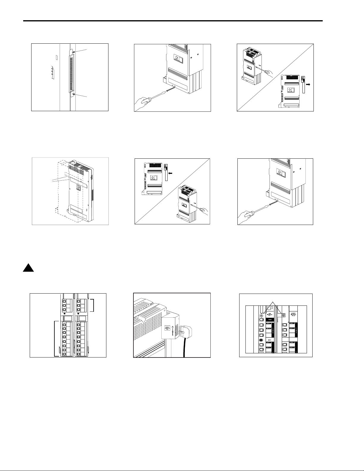
Ta b
Ta b
Remove the clear, plastic protector from the
1 3
connector on the rear of the new module
(and the processor module if you are
upgrading from a stand-alone system) by
grasping the tabs and lifting.
Mounting
Tracks
A) Slide the second module off the processor
module and put it aside.
4
B) Slide the new module onto the processor
module, making sure the mounting tracks
interlock.
!
CAUTION:
Do not force the module. If the module
does not insert easily, remove it, clear
any obstruction, and reinsert it.
1
4
308EC
Module
18
19
20
21
22
23
24
25
Lines
5
6
2
3
ACS
Proc
10
11
12
Extensions
A) Label the line and extension jacks.
7
B) Connect the line and telephone cords to
the appropriate jacks on the new module.
C) Route each cord through the hook on the
front of its module.
D) Connect the free end of each line cord to
the appropriate network interface jack.
E) Connect the free end of each telephone
cord to the modular connecting blocks for
system extensions.
F) Gather the line and extension cords
hanging below the hook and twist tie or wire
wrap them.
13
14
15
16
17
A) Before starting, remove the power cord
2
from the wall outlet.
B) Remove the screw from the bottom of the
wall-mounted module or modules.
C) If you are upgrading an existing
stand-alone system, skip to Step 4B.
Attach the 2-Slot Carrier to the top right
side of the two modules:
5
A) Align the carrier carefully and then push
firmly until the connectors on the modules
snap into the carrier.
B) Fasten the carrier to the modules using
the two #4 screws included with the carrier.
Press the power cord firmly into the power
jack on the carrier. Plug the other end of the
8 9
power cord into a properly grounded
three-prong wall outlet not controlled by a
switch.
If you are replacing the second module in a
2-Slot Carrier, remove the two screws
holding the carrier in place and gently pull
the carrier off the modules.
Re-insert the screw into the bottom of the
modules. Tighten it until the processor
6
module is flush against the wall. Do not
overtighten or the module will warp.
Lights (LEDs)
1
2
3
10
11
Check the green lights on the fronts of the
modules:
A) If a single light is out, power down the
carrier, reseat the module, and then power
up the carrier.
B) If both green lights are out, power down
the carrier, reseat both modules, and then
power up the carrier.
C) If the lights are still out, see the Customer
Support Document on the accompanying
compact disc for information about whom
you should contact.
4
5
6
18
19
Page 3

Using a 5-Slot Carrier
IMPORTANT: The 5-slot carrier and the processor module must already be mounted on the wall. If it is not, refer to
the documentation that came with your system.
5-Slot Carrier
A) Move the carrier’s On/Off switch to “Off,”
1
and unplug the power cord from the wall
On/Off Switch
Power
Jack
outlet.
B) To remove the cover on Release 3.0 or
earlier systems, loosen the screw on the
lower front of the cover.
C) Place one hand on the handle on the
bottom front of the cover, and place your
other hand on the top of the cover. Gently
pull the cover up and away from the carrier.
1600 DSL
308EC
Processor
P
A
R
T
N
E
R
3
0
0
0
P
A
R
T
N
E
R
3
0
0
0
If you are removing an existing module, see if
2
there is enough slack to remove the module
without pulling the line and extension cords
free. If necessary, label and disconnect the
cords. Then, grab the center of the module
with one hand. With the other hand, push up
on the plastic tab at the top of the slot on the
carrier and pull out the old module.
Ta b
Ta b
Before installing any modules, remove the
3
clear, plastic protector from the connector on
the rear side of the module by grasping the
tabs and lifting.
5-Slot Carrier
P
A
R
T
N
E
R
3
0
0
0
P
A
R
T
N
E
R
3
0
0
0
P
A
R
T
N
E
R
3
0
0
0
P
A
R
T
N
E
R
3
0
0
0
P
A
R
T
3
0
0
On/Off Switch
N
E
R
0
Power
Jack
PFT
L
I
N
E
S
PFT
E
X
T
E
N
S
I
O
N
S
A) Verify that the processor module is in the
center slot of the carrier. In the other slots,
4
from left to right, install modules in this order:
1600 DSL, 308EC(s), 012E, 206(s), then
400(s) or 200(s).
NOTE: If you intend to use the FAX CNG
Detection feature (with ACS), for optimal
performance, insert the 308EC R3.0
module to the left of any 308EC module
prior to R3.0.
B) Align the module carefully in the
appropriate slot. On a Release 4 carrier, lift
the plastic latch on the top of the carrier.
Push slowly but firmly in the center of the
module until the connectors on the module
lock into place and the module is attached to
the rear of the carrier. On a Release 4
carrier, check that the plastic latch on top of
the carrier is secured in the rounded slot on
top of the module (See CAUTION on the last
page.)
!
CAUTION:
Do not force the module. If the module
does not insert easily, remove it, clear
any obstruction, and reinsert it.
L
S
D
0
C
0
E
6
8
1
3
r
0
o
s
s
le
e
u
c
d
ro
o
P
M
A) Label the line and extension jacks.
5
B) Connect the line and telephone cords to
the appropriate jacks on the new module.
C) Route each cord through the hook on the
front of its module.
D) Connect the free end of each line cord to
the appropriate network interface jack.
E) Connect the free end of each telephone
cord to the modular connecting blocks for
system extensions.
F) Gather the line and extension cords
hanging below the hook and twist tie or wire
wrap them.
G) Place the bundle of wires in the
indentation on the bottom of the carrier.
A) Plug the power cord into a properly
grounded three-prong wall outlet not
6
controlled by a switch.
B) Power up the control unit by moving the
On/Off switch to the “On” position.
Lights
23
20
1
21
2
22
3
26
24
27
25
28
Check the green lights on the fronts of the
modules:
7
A) If a single light is out, power down the
carrier, reseat the module, and then power
up the carrier.
B) If multiple green lights are out, power
down the carrier, reseat the leftmost module
that has a light out, and then power up the
carrier.
C) If the lights are still out, see the Customer
Support Document on the accompanying
compact disc for information about whom
you should contact.
Page 4

CAUTION
The plastic latches on top of the Partner 5 Slot
Carrier must be secured properly on all Modules.
Make sure the plastic latches are completely down
and the round nubs are snapped in place (Figure A).
Failure to properly secure the plastic latches will
result in loss of power to the Modules (Figure B).
Figure A
(Correct)
Figure B
(Incorrect)
 Loading...