

Avanti DOLPHIN A-V164 Original Instructions Manual
AVANTI SERVICE LIFT
Installation and Maintenance Manual
Model Service Lift DOLPHIN A-V164
Original instructions
®
AT00014349_Dolphin A-V164_Maintenance and Installation Manual E01R03.indd 1 6/11/2018 2:03:51 PM

Certificate of Dolphin A-V164
AT00014349_Dolphin A-V164_Maintenance and Installation Manual E01R03.indd 2 6/11/2018 2:03:51 PM
Date of publication:
1st CE Edition: 09/2017
Revision 4: 11/06/2018
Manufacturer:
AVANTI Wind Systems A/S
Rønnevangs Allé 6
3400 Hillerød Denmark
P: +45 4824 9024
F: +45 4824 9124
E: info@avanti-online.com
I: www.avanti-online.com
Sales & Service:
Australia Avanti Wind Systems PTY LTD P: +61 (0) 3 9585 1852 3 9585
China Avanti Wind Systems P: +86 21 5785 8811
Denmark Avanti Wind Systems A/S P: +45 4824 9024
Germany Avanti Wind Systems GmbH P: +49 (0) 41 21-7 88 85 – 0
Spain Avanti Wind Systems SL P: +34 976 149 524
UK Avanti Wind Systems Limited P: +44 0 1254 399923
USA Avanti Wind Systems, Inc P: +1 (262) 641 9101
India Avanti Wind Systems India (P) Ltd P: +91 95 00 173 492
Brazil Avanti Brasil Sistema Eólicos LTDA P: +55 85 9 9955-0090
Manufactured Under Process Patent NO.8,499,896.
® Registered in Europe
AT00014349_Dolphin A-V164_Maintenance and Installation Manual E01R03.indd 3 6/11/2018 2:03:51 PM

Page
1. Limited warranty................................................................5
2. Introduction....................................................................6
2.1 Observations ............................................................... 6
2.2 Symbols ...................................................................6
2.3 Cautions ....................................................................7
2.4 Terms and definitions .........................................................7
3. Installation ....................................................................8
3.1 WTG integration requirements ..................................................8
3.2 Cautions ...................................................................9
3.3 Freight kit ..................................................................9
3.4 Electrical connections ....................................................... 9
3.4.1 Power cable............................................................10
3.4.2 Guard locking system ...................................................10
3.5 Guiding, traction and safety wire ropes..........................................10
3.5.1 Top platform ...........................................................10
3.5.2 Bottom platform .......................................................10
3.6 Wire rope fix. ...............................................................12
3.7 Danger zone sticker..........................................................13
3.8 Rescue guide ...............................................................13
3.9 Inspection before first use ................................................... 13
4. Maintenance ..................................................................14
4.1 Recommended planning ......................................................14
4.2 Alternative planning..........................................................14
4.3 Cautions ...................................................................15
4.4 Daily inspection .............................................................15
4.5 Annual inspection ...........................................................16
4.5.1 Cabin .................................................................16
4.5.2 Traction hoist ..........................................................16
4.5.3 Fall arrest device .......................................................16
4.5.4 Traction, safety and guiding wire ropes .....................................16
4.5.5 Guiding system.........................................................18
4.5.6 Electrical cables ........................................................18
4.5.7 Overload check and adjustment ...........................................18
4.5.8 Information signs and documents..........................................18
4.6 Repairs ....................................................................18
4.7 Ordering spare parts ........................................................18
Appendix A: Adjustment of the overload limiter ........................................19
Appendix B: Inspection Checklist....................................................21
Appendix C: Inspection Log Sheet ...................................................25
Appendix D: AVANTI lift anchor . .....................................................29
Contents
AT00014349_Dolphin A-V164_Maintenance and Installation Manual E01R03.indd 4 6/11/2018 2:03:51 PM

5
Maintenance and Installation Manual
1)
Avanti service lift (“Product”)
Avanti Wind Systems A/S warrants that commencing from the date of shipment to the
Customer and continuing for a period of the
longer of 365 days thereafter, or the period set
forth in the standard AVANTI warranty, the
Product1) described in this Manual will be free
from defects in material and workmanship
under normal use and service when installed
and operated in accordance with the provisions
of this Manual.
This warranty is made only to the original user
of the Product. The sole and exclusive remedy
and the entire liability of Avanti under this
limited warranty, shall be, at the option of
Avanti, a replacement of the Product (including
incidental and freight charges paid by the
Customer) with a similar new or reconditioned
Product of equivalent value, or a refund of the
purchase price if the Product is returned to
Avanti, freight and insurance prepaid. The
obligations of Avanti are expressly conditioned
upon return of the Product in strict accordance
with the return procedures of Avanti.
This warranty does not apply if the Product (i)
has been altered without the authorization of
Avanti or its authorized representative; (ii) has
not been installed, operated, repaired, or
maintained in accordance with this Manual or
other instructions from Avanti; (iii) has been
subjected to abuse, neglect, casualty, or
negligence; (iv) has been furnished by Avanti to
Customer without charge; or (v) has been sold
on an “AS-IS” basis.
Except as specifically set forth in this Limited
Warra nty,
ALL EXPRESS OR IMPLIED CONDITIONS,
REPRESENTATIONS AND WARRANTIES,
INCLUDING, BUT NOT LIMITED TO, ANY
IMPLIED WARRANTY OR CONDITION OF
MERCHANTABILITY, FITNESS FOR A PARTICULAR PURPOSE, NON-INFRINGEMENT,
SATISFACTORY QUALITY, COURSE OF DEALING, LAW, USAGE OR TRADE PRACTICE ARE
HEREBY EXCLUDED TO THE MAXIMUM
EXTENT PERMITTED BY APPLICABLE LAW
AND ARE EXPRESSLY DISCLAIMED BY
AVANTI. IF, PURSUANT TO ANY APPLICABLE
LAW, TO THE EXTENT AN IMPLIED WARRANTY CANNOT BE EXCLUDED AS PROVIDED IN
THIS LIMITED WARRANTY, ANY IMPLIED
WARRANTY IS LIMITED IN TIME TO THE SAME
DURATION AS THE EXPRESS WARRANTY
PERIOD SET FORTH ABOVE. BECAUSE SOME
STATES DO NOT PERMIT LIMITATIONS ON
THE DURATION OF IMPLIED WARRANTIES,
THIS MAY NOT APPLY TO A GIVEN CUSTOMER. THIS LIMITED WARRANTY GIVES CUSTOMER SPECIFIC LEGAL RIGHTS, AND
CUSTOMER MAY HAVE OTHER LEGAL
RIGHTS UNDER APPLICABLE LAWS.
This disclaimer shall apply even if the express
warranty fails of its essential purpose.
In any cases of dispute the English original shall
be taken as authoritative.
1. Limited Warranty
AT00014349_Dolphin A-V164_Maintenance and Installation Manual E01R03.indd 5 6/11/2018 2:03:51 PM
6
AVANTI Service Lif t for Wind Turbines
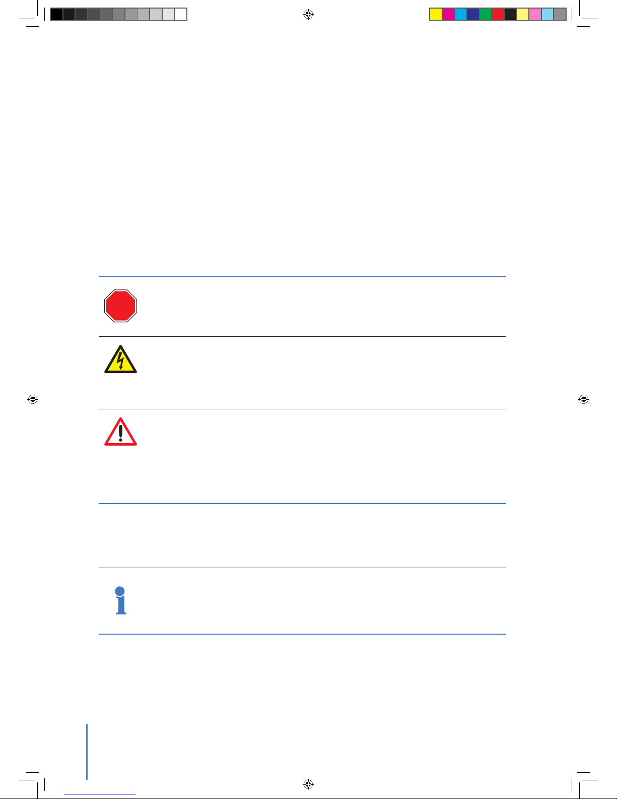
2.2 Symbols
2.1 Observations
2. Introduction
Only trained people may use this lift.
This manual must be available to staff at all times during installation, maintenance and operation.
Additional copies are available from the manufacturer upon request.
This manual, including, but not limited to, measurements, procedures, components, descriptions, instructions, recommendations and requirements, is subject to change without prior notice. Please check Avanti
website/manuals for the latest revisions of the manuals.
Any additional cost related to or arising from any changes in the manuals does not entitle Customer to any
form of compensation or other legal remedies.
The pictures and sketches in this manual may not reflect the product aesthetics, colours,
arrangement precisely. This has no impact on the function or safety.
!
STOP
!
Symbol Signal word Meaning Possible injury if not observed
Safety instructions
DANGER!
IMMEDIATE or
possibly imminent
danger:
Death or severe injury!
DANGER!
IMMEDIATE or
possibly imminent
danger of hazardous
voltage:
Death or severe injury!
CAUTION! Potentially hazardous
situation:
Light injury or material damage.
Additional instructions
ATTENTION!
Potentially dangerous
situation:
Damage to equipment or workplace
IMPORTANT!
Useful tips for optimum
working procedure
None
Reference to written
specification/documentation
AT00014349_Dolphin A-V164_Maintenance and Installation Manual E01R03.indd 6 6/11/2018 2:03:52 PM
7
Maintenance and Installation Manual
2.3 Cautions
Use and daily inspection of the service lift shall only
be performed by person who has gone through the
relevant training associated with the Avanti service
lift use and daily inspection and is in possession of a
valid (non expired) certificate for the task.
Installation and maintenance of the service lift shall
only be performed by Certified technicians.
Personnel must be at least 18 years of age.
The staff must be familiar with the relevant accident
prevention instructions and must have received
proper training in these.
Personnel are obliged to read and understand this
User’s Manual.
Personnel shall wear PFPE (safety helmet, full body
harness, shock absorber, lanyard and slider) at all
times.
A copy of the User’s Manual must be handed out
to the personnel and must always be available for
reference.
If more than one person is entrusted with one of
the above tasks, the employer shall appoint a
supervisor in charge of the operation.
Self-locking nuts must be used at all times. The
screw must extend from the nut by at least half
of the thread diameter. The nut may not be used once
it has become possible to loosen by hand!
If any damage or faults are found during operation,
or if circumstances arise which may jeopardize
safety: immediately interrupt the work in progress
and notify the supervisor or employer!
All tests/repairs of electrical installations may only
be performed by a certified technician.
All repairs to the traction, braking and supporting
systems may only be performed by a certified technician.
If any supporting parts are repaired or replaced,
the operational safety of the system must be tested
and verified by a certified technician.
Only original fault-free parts may be used.
Use of non-original parts will render the manufacturer’s warranty void and any type approval invalid.
No modification, extension or reconstruction of the
service lift is allowed without the manufacturer’s prior
written consent.
No warranty is provided against damage resulting
from reconstruction or modification of equipment or
use of non-original parts which are not approved by
the manufacturer.
Service lift must be inspected by a certified technician before first use.
Service lift must be inspected at least once a year
by a certified technician. In case of high operating
frequency or severe conditions of use, more frequent
inspection is required.
Service lift is designed for a lifetime of 25 years with
an operating frequency of approximately 10h/year
(250 h in total).
Service lift may not be used by persons who are
under the influence of alcohol or drugs which may
jeopardize working safety.
The service lift shall not be used in case of fire in the
tower.
Service lift shall ONLY be used when the turbine is
not generating power.
All wind farm site specific rules must be followed.
Service lift shall not be used during inclement weather, including wind speeds over 25 m/s (55.5 mph).
Avoid injury – follow all instructions!
Owner must verify the need for third party service lift inspections with the local
authority and comply with the standards
specified.
2.4 Terms and definitions
Terms Definitions
Certified technician
Person who has gone through the relevant training associated with the scheduled task from Avanti
or from a cer tified trainer and is in possession of a valid (non expired) certificate for the task.
User
Person who has gone through the relevant training associated with the Avanti service lift
use and daily inspection and is in possession of a valid (non expired) certificate for the task.
Manual descent
Action performed to descend the lift at a controlled speed without power supply by manually
opening the hoist electromagnetic brake. (Also manual no-power descent)
AT00014349_Dolphin A-V164_Maintenance and Installation Manual E01R03.indd 7 6/11/2018 2:03:52 PM
8
AVANTI Service Lif t for Wind Turbines
3. Installation
3.1 WTG integration requirements
WTG
component
General integration requirements
Service lift Dolphin A-V164
Power supply Ty pe 3 Phase + PE + N
1)
Voltage (50 Hz) 400 V/ 690 V
Voltage (60 Hz) 400 V/ 690 V
Fuses 16 A
Protection According to EN
602 04-1
Platforms Minimum clearance
around service lift
50 mm
2)
Evacuation
way
Means of evacuation
shall be provided
with a maximum
distance of
1100 mm
Platform
fences
Minimum height 110 0 m m
Compliant to
requirements of
standard
EN 14122-3
Fence door interlock system
Trapped key or
guard locking
Hoistway Maximum total
travel height
See note (3)
Maximum angle
between hoistway
and vertical axis
±5,3º
Top b e am Forces capable to
withstand
Upon request
from AVANTI
1) Note: Neutral applies only to 40 0 V.
2) Note: Up to a minimum value of 40 mm. af ter evaluation
and approval by Avanti
3) Note: With all options: 135 m. / Standard design: 160 m.
Depending on travel path, dimensions may need to be
larger in order to avoid collisions of travelling cable pulley
with platforms. Other dimensions are possible upon
request and design verification by AVANTI.
The WTG manufacturer shall put in place any other
means necessary to ensure the safe use of the service
lift according to AVANTI recommendations and its own
risk assessment for the integration that shall include
items which are not under AVANTI´s scope.
In the event of installation procedure divided into two
different stages and extension of travel path is needed
(e.g.: offshore configuration):
There is a first assembled onsite at harbor stage were
some of the lift components are preassembled by the
tower manufacturer. All the wire ropes have to be
tightened at provisional bottom platform and the extra
length coiled up in a secure manner to prevent damages
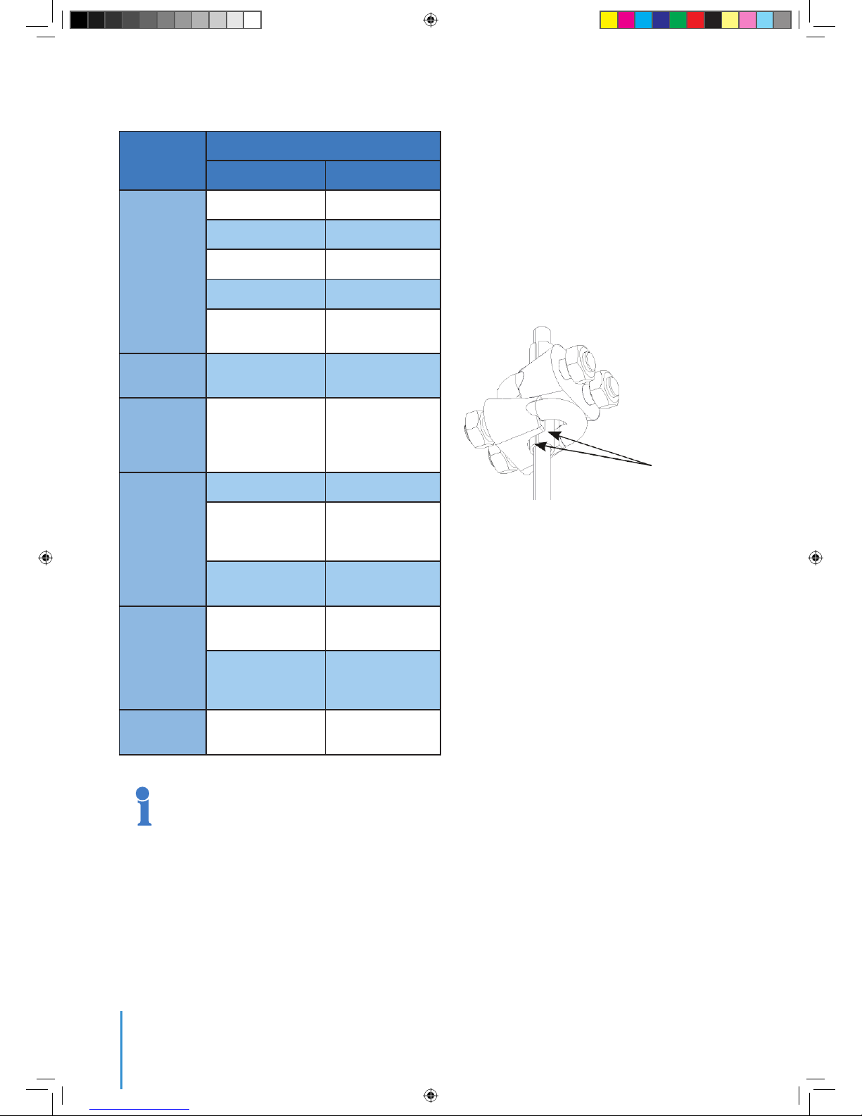
in them since they have to be used for the final extension. Half bushings must be installed to protect wire
ropes (traction, safety and guiding) before travelpath
extension.
The assembly of the tower to the offshore foundation
extending the operation of the service lift to the transition
piece (TP) will be undertaken in the second stage.
In this second stage, TP bottom platform will be the final
low travel end of the lift, and therefore when the tower is
located over the TP, the Control Box previously mounted
on first stage provisional bottom platform will be
disassembled and re-mounted on the TP Bottom
Platform.
When the travel path of the cabin is extended to TP
bottom platform, travelling cable and wire ropes need to
be longer, for this reason, these are previously ready
coiled on the first stage.
Half bushings
AT00014349_Dolphin A-V164_Maintenance and Installation Manual E01R03.indd 8 6/11/2018 2:03:52 PM
 Loading...