

Page 1
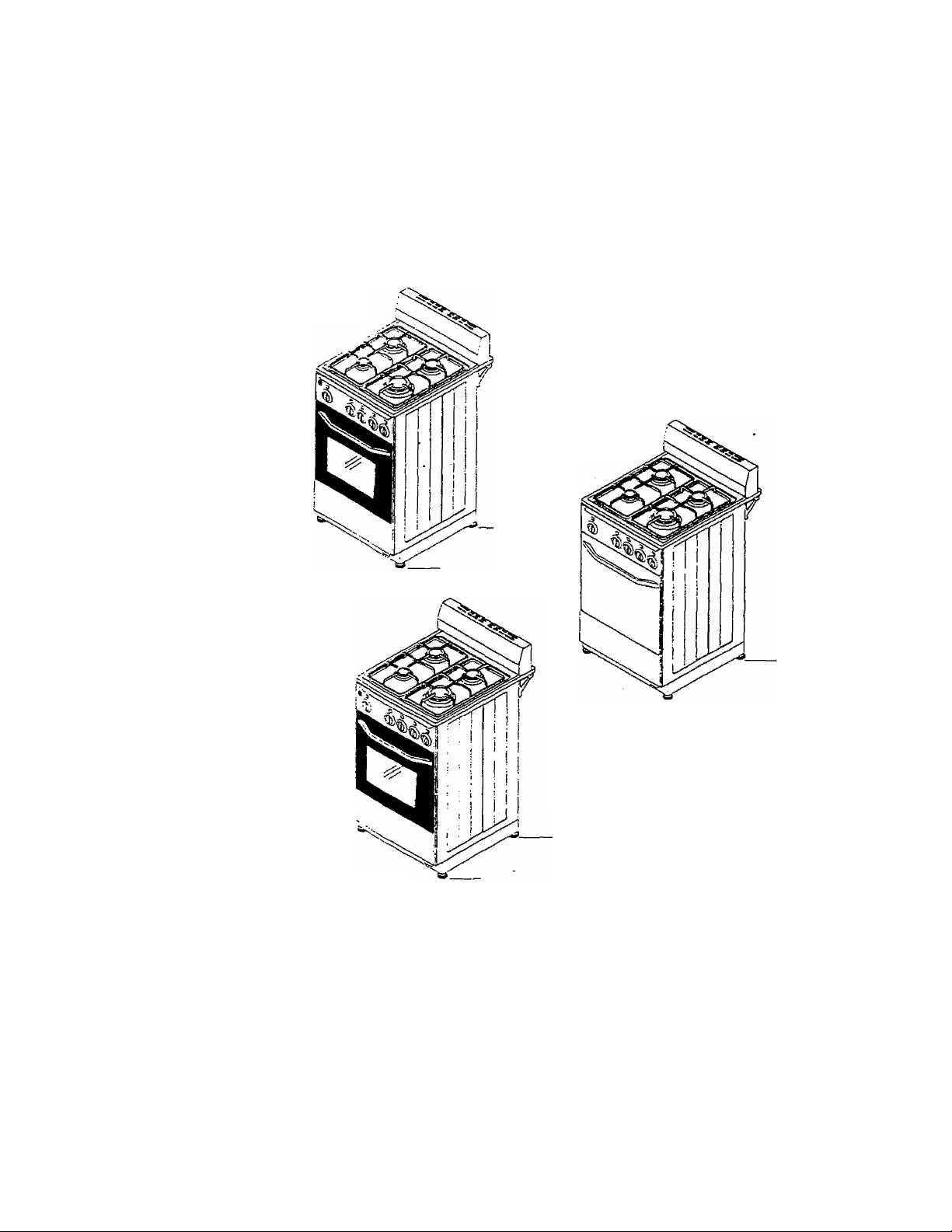
DG24CSS
GAS RANGE
INSTRUCTION MANUAL
G24AW
DG24CW
CAUTION:
BEFORE USE. PLEASE READ AND FOLLOW ALL SAFETY RULES AND OPERATING
INSTRUCTIONS '
Avanti has a policy of continuous .mprovement on its products and reserves the right to change materials and specifications without
notice. .
Avanti Products, A Division of The Mackle Co., Inc.
P.O. Box 520604 - Miami, Florida 33152
www.avantiproducts.com
ISOIIOBSiRO
Page 2

IMPORTANT SAFETY INSTRUCTIONS
Gas ranges have been thoroughly tested for safe and efficient operation. However, as with any
appliance, there are specific installation and safety precautions that must be followed to ensure safe and
satisfactory operation. Have your range installed by a qualified installer.
awarning-j;
To reduce the risk of fire, electrical shock, or injury when using your gas range, follow these
precautions:
• Read all instructions before using this appliance.
• Grounding Instructions
This appliance must be electrically grounded in accordance with local codes. In the event of
an electrical short circuit, grounding reduces the risk of an electrical shock. This appliance
is equipped with a three-prong cord with a ground plug. Do not, under any circumstances,
cut or remove the ground prong from the power cord supplied with this appliance. This
appliance must be plugged into an outlet that is properly grounded. Do not use an adapter
plug. Using an extension cord is not recommended. Consult a qualified electrician for any
questions as to whether your home or business has the proper electrical grounding
connections.
• Child Safety
An emphy appliance can be a dangerous attraction to a child. Never allow children to play
with or crawl inside the appliance. Remove the door, door gasket, latches, or lids before
storing or abandoning the appliance.
• Never clean the appliance with flammable liquids. The fumes can create a fire hazard or
explosion.
• Do not store or use gasoline or other flammable products in the vicinity of this appliance.
The fumes can create a fire hazard or explosion._______________________________________
______________________
_
A WARNING: If the information in this manual is not followed exactly, a
fire or explosion may result causing property damage, personal injury or
death. '
-Do not store or use gasoline or other flammable vapors and liquids in the vicinity of
this or any other appliance.
-WHAT TO DO IF YOU SMELL GAS
• Open windows. **
• Do not try to light any appliance.
• Do not touch any electrical switch; do not use any phone in your building.
• Immediately call your gas supplier from a neighbor’s phone. Follow the gas
supplier’s instructions.
• If you cannot reach your gas supplier, call the fire department.
- A qualified installer, service agency, or the gas supplier must perform installation
and service.
16C' * D35(R0
Page 3

WARNING
Tip Over Hazard
Connect anti-tip bracket to the floor.
Reconnect anti-tip bracket if the range is moved:
Do not push down on the open oven door.
Follow the installation instructions.
Do not let children climb, stand, or hang on the oven door.
Failure to do so can result in death, burns, or other injury.
A WARNING
• ALL RANGES
CAN TIP
v^y
(Si)
•INJURYTO PERSONS
COULD RESULT
- INSTALL ANTI-TIP
DEVICES PACKED
WITH RANGE
- SEE INSTALLATION
INSTRUCTIONS
SAFETY PRECAUTIONS
After prolonged use of a range, high floor temperatures may result. Many floor covering's will not
withstand this kind of use. Before installing your range on linoleum or any other synthetic floor
covering, make sure the floor covering can withstand 100'* without shrinking, warping or discoloring.
Do not install the range over carpeting unless a sheet of V4" thick plywood or similar insulator is
placed between the range and carpeting.
Do not leave children alone or unattended where a range is hot or in operation.
Never use your appliance for heating the room. Your oven and cooktop are not designed to heat your
kitchen. Top burners should not be operated without cookware.
Do not let cooking grease accumulate in or near the range.
Never pick up a flaming pan. Turn the controls off.
Smother a flaming pan on a surface unit by covering the pan completely with a well fitting lid.
Do not use water on grease fires. Flaming grease outside a pan can be put out by covering it with
baking soda, multipurpose dry chemical, or fire extinguisher. Flame in the oven can be smothered
completely by closing the oven door'and turnirtg the oven off or by using baking soda, multipurpose
dry chemical, or fire extinguisher.
Do not store or use combustable materials in an oven, broiler, storage drawer, or near the cooktbp.
Never wear loose fitting or hanging garments while using the appliance. Be careful when reaching for
items stored in cabinets over the cooktop. Flammable material could be ignited if brought in contact
with flames or hot oven surfaces and may cause severe burns.
Never leave the surface burners unattended at high flame settings.Boilovers cause smoking and
greasy spillovers may catch fire.
Adjust the top burner flame size so it does not extend beyond the edge of the cookware.Excessive
flame is hazardous.
3
!6011085/R0
Page 4

SAFETY PRECAUTIONS continued...
Use only dry pot hciders-moist or damp potholders on hot surfaces may result in burns from steam.
Do not let potholders come near open flames when lifting cookware.
Turn cookware hancies toward the side or back of the range without letting them extend over
adjacent burners, tc .minimize the possibility of burns.
Always turn the surface burners to OFF before removing cookware.
Never block the vents (air openings) of the range. They provide the air inlet and outlet that are
necessary for the ra.nge to operate properly with correct combustion.
Foods for frying should be as dry as possible. Frost on frozen foods or moisture on fresh foods can
cause hot fat to bubble up and over the sides of the pan. Use the least possible amount of fat for
effective shallow or beep-fat frying. Filling the pan too full of fat can cause spillovers when food is
added.
If a combination of oils or fats will be caused in frying, stir together before heating or as fats melt
slowly.
Always heat fat slowly and watch as it heats.
Use a deep-fat thermometer whenever possible to prevent overheating fat beyond the smoking point.
Never try to move a pan of hot fat; especially a deep fat fryer. Wait until the fat is cool.
When using glass cookware, make sure it is designed for top-of-range cooking.
Use proper pan size. Avoid pans that are unstable or easily tipped. Select cookware having fiat
bottoms large enough to properly contain food and avoid botlovers and spillovers.
Do not leave any kerns on the cooktop. The hot air from the vent may ignite flammable items and will
increase pressure ir closed containers, which may cause them to burst.
Do not use the oven as a storage area. Items stored in the oven can ignite.
Stand away from the range when opening the door of a hot oven. The hot air and steam that escape
can cause burns to hands, face, and eyes.
Keep the oven free тот grease buildup.
Place the oven shelves in the desired position while the oven is cool.
Do not heat unopened food containers. Pressure could build up and the container could burst,
causing an injury.
Do not use aluminum foil anywhere in the oven except as described in the manual. Misuse could
result in a fire hazarc or damage to the range.
When using cooking or roasting bags in the oven, follow the manufacturer instructions.
Use only glass cock.vare that is recommended for use in gas ovens.
When broiling, if meat is too close to the flame, the fat may ignite. Trim excess fat to prevent
excessive flare-ups
Never entirely cove.' э shelf with aluminum foil. This will disturb the heat circulation and result in poor
baking. '
Your oven temperature s controlled very accurateiy using an oven control system. It is recommended
that you operate the eve:" for a number of weeks to become familiar with your new oven’s performance.
To avoid possible corns, place the shelves in the correct position before you turn the oven on.
Close the oven doer Turn the oven set knob to the temperature you desire.
Check the food for ceneness at the minimum time on the recipe. Cook longer if necessary.
Turn the oven set kreb to off and then remove the food.
Stand away from the range when opening the door of a hot oven. The hot air and steam that escape
can cause burns tc "ands. face, and eyes.
'601108S/RO
Page 5

Table of Contents
Important Safety instructions
Installation Instructions
Before Using Your Gas range
Installation Requirements for Your Gas Range.
Material Requirements
Space Requirements
Gas Requirements
Electrical Requirements.
Installation of Your Gas range.
Leveling of Range _________
Anti-Tip Bracket Installation.
Electrical Connection
Mobile Home Installation
Operating Your Gas Range
Operating Your Surface Burners
To Light the Desired Surface Burner
Operabng Your Oven Burner
Using Your Oven
Oven Light
Using the Broiler Tray
Operating Your Broiler Burner.
Care and Maintenance
Removing The Oven Door for Cleaning
Cleaning the Oven
Cleaning the Knobs and Control Panel
Cleaning the Cooking Supports, Cooktop, Backguard, and Surface Burners
Helpful Hints___________________________________________________
Troubleshooting Guide.
Service For Your Gas range.
Your Avanti Products Warranty.
Help Us Help You
_____________________—
______
____________
__________^__________
___________________
________________________
____________
_____
________
_______________
_________
________
___________________
_____________
„
_
__
_
______
_
10
__
12
__12
_12
_13
_ 13
__ 13
_ 13
__14
__ 14
__14
_ 15
„16
_17
16011C85.RC
Page 6

INSTALLATION INSTRUCTIONS
aWARNING
HAVE THIS RANGE INSTALLED BY A QUALIFIED INSTALLER.
Improper installation, adjustment, alteration, services, or
maintenance can cause injury or property damage. Consult a
qualified installer, service agency, or the gas supplier.
Before Using Your Gas Range
• Remove the exterior and interior packing.
• Check to be sure you have all of the parts listed below:
• Oven Rack
■ Orifice Packet
• Anti-tip bracket
« 4 leveling legs
■ 2 cooking grids
■ 4 caps and 4 rings in the burner assembly
- 4 burner knobs
• 1 oven knob
■ Broiler Tray
• Clean the interior surface with lukewarm water using a soft cloth. (See “Cleaning” on
Page 13)
• Have the installer show you the location of the ranges gas shut-off valve and how to
shut it off if necessary.
• Have your range installed and properly grounded by a qualified installer in
accordance with the Installation Instructions.
• Do not attempt to repair or replace any part of your range unless it is specifically
recommended in this manual.
• Be sure your range is correctly adjusted by a qualified service technician or installer
for the type of gas (natural or UP) that is being used.
Installation Requirements for Your Gas Range
Material Requirements
• Gas line shutoff valve .
• 1/2" NPT male pipe thread for connection to pressure regulator
• L.P. Gas resistant pipe-joint compound
• AGA or CGA design-certified flexible metal connector (4-5 feet) or rigid gas supply line as
needed
• Insulated pad or t/2" plywood if range is installed over carpeting.
1601 lOSE/RO
Page 7
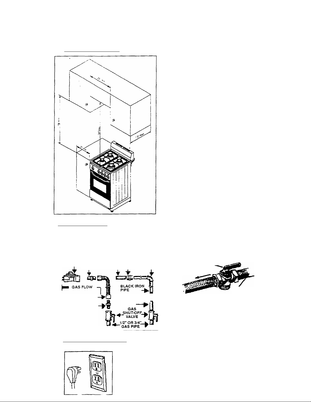
Space Requirements
0” to rear and 0” sides below
cooktop.
3” to sides from cooktop to 18'
above the level of cooking
surface.
30” to bottom of wall cabinets
over cooktop.
Range dimensions:
Width
Depth
Height
24”
24”
35”
Gas Requirements
TYPICAL CONNECTIONS
FLEXIBLE CONNECTOR HOOK UP RIGID PIPE HOOK UP
PRESSURE
REGULATOR UNION
FLEX CONNECTOR-
ADAPTER
ADAPTER NIPPLE |
UNION
NIPPLE
Electrical Requirements
120-VOLT. 60 HZ. 15 AMP MINIMUM
GAS SHUT OFF VALVE
MANUAL SHUT OFF VALVE
"OPEN" POSmON
TO RANGE
GAS
SUPPLY
16011C8£*Fi
Page 8
INSTALLATION OF YOUR GAS RANGE
aWARNING®
HAVE THIS RANGE INSTALLED BY A QUALIFIED INSTALLER.
Improper installation, adjustment, alteration, services, or
maintenance can cause injury or property damage. Consult a
qualified installer, service agency or the gas supplier.
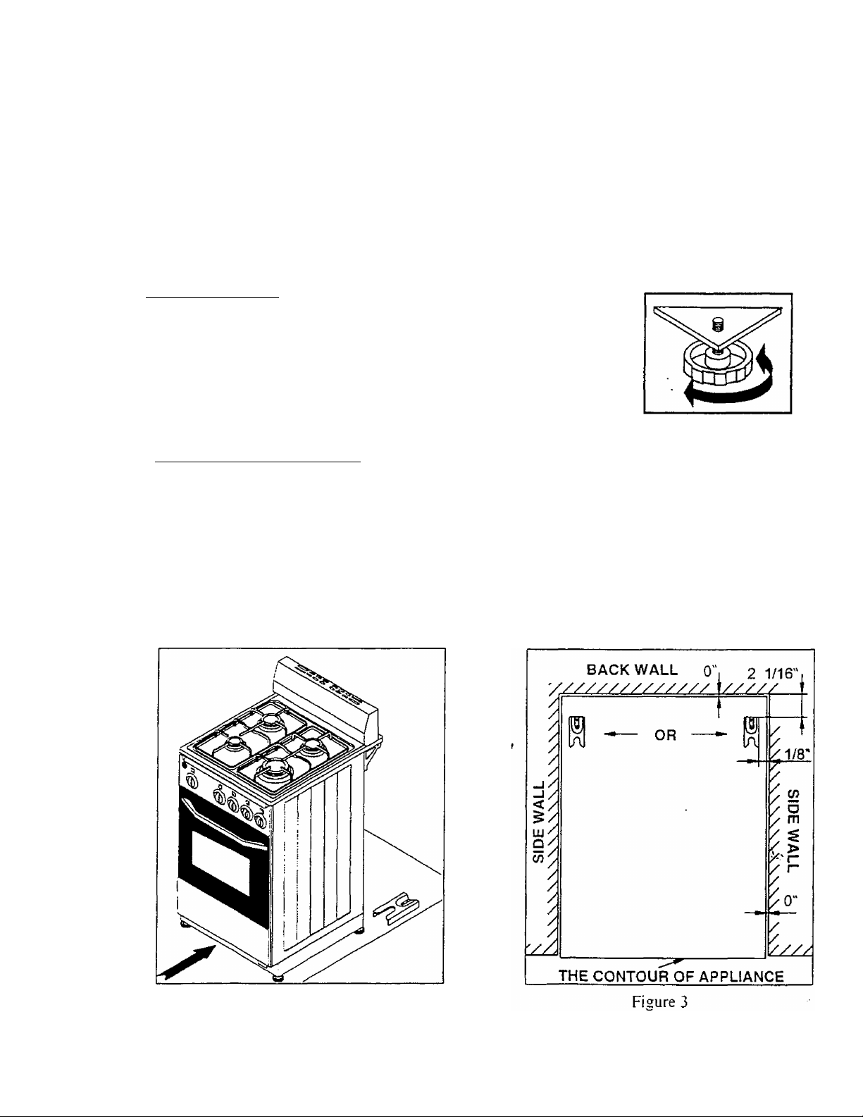
^ Leveling of Range
The range must be level to obtain proper cooking results. The screwed
leveling legs located on the corner brackets at the bottom of range
should be adjusted by turning them clockwise to make the range higher
or counter-clockwise to lower the range until the range is level (See
Figure 1). Use a level on the cookware supports to check the leveling of
the range.
Fi2ure 1
Anti-Tip Bracket Installation
To reduce the risk of tipping the appliance by abnormal usage or improper door loading, the
appliance must be secured by properly installing the anti-tip device packed with the
appliance.
1. Place the anti-tip bracket on the floor as shown in Figure 3. If there is no sidewall, the
dimension given as 1/8" will be the distance of right/left side of appliance to right/ieft side
of anti-tip bracket. Anti-tip bracket can be installed on either right or left side.
2. Mark the locations of 2 holes of anti-tip bracket on the floor.
3. Use a 5/16" masonry drill bit and insert plastic anchor.
4. Secure bracket to floor using screws supplied.
5. Slide appliance into position. (Figure 2)
Fieure 2
leCnOSEjRQ
Page 9
Electrical Connection
• Electrical connection must be made in accordance with local codes or in absence of
local codes, with the National Electrical Code, ANSllNFPA No.70-Latest Edition.
• Connect the 2-prong supply cord to a 120-volt. 60 Hz. 2-prong wall receptacle,
• Electrical connection must not interfere with gas connection.___________________
Warning
Improper use of the grounded plug can result in a risk of electrical shock. If the power
cord is damaged have it replaced by an authorized Avanti Products Service Center.
^ Mobile Home Installation
The installation of this range must conform with the Manufactured Home construction and
Safety Standard, Title 24 CFR. Part 3280 (formerly the Federal Standard for Mobile Home
Construction and Safety. Title 24, HUD (Part 280}} or. when such standard is not applicable, the
Standard for Manufactured. Home Installations. ANSI A 225.1 and Manufactured Home
Installations. Sites, and Communities ANSI/NFPA 501 A, or with local codes.
When this range is installed in a mobile home, it must be secured to the floor during transit. Any
method of securing the range is adequate as long as it conforms to the standards listed above.
Copies of the standards may be obtained from;
National Fire Protection Association
Batterymarch Park
Quincy, MA 02269
American Gas Association
1515 Wilson Blvd.
Arlington. VA 22209
OPERATING YOUR GAS RANGE
Before operating the unit, read this section thoroughly.
The first time the burners are used, a small amount of
smoke may be generated due to burning of grease on the
burners, especially on oven and broiler burners. VThis is not
dangerous. For that reason, the burners must be operated
without any cooking purpose for 10 minutes for the first
time. This range is equipped with an electric ignition
system to ignite the burners. Therefore, it must be
supplied with electricity. If any electric power failure
occurs, using a match can ignite the burners. A constant
supply of air is needed for combustion. Therefore, allow
sufficient ventilation into the room where the range is
placed.
Page 10

Manual Lighting Of The Oven Burner During Power Outage
You should place a lighted match next to the entrance of the burner hole. Depress the oven burner knob
and turn counter-clockwise. Keep the control knob depressed for 10 seconds after lighting. Check that
the burner is lit (Figure 5). Use extreme caution when lighting burners in this manner.
^ Operation of Surface Burners
There are 3 different types of surface burners with different size and heat output on the cook
top.
A rapid burner (Front Right)
Two semi-rapid burners (Back)
A simmer burner (Front Left)
A WARNING L-
DO NOT ATTEMPT TO OPERATE ANY SURFACE BURNER WITHOUT
INSTALLING IT. OTHERWISE. THERE IS A RISK OF EXPLOSION.
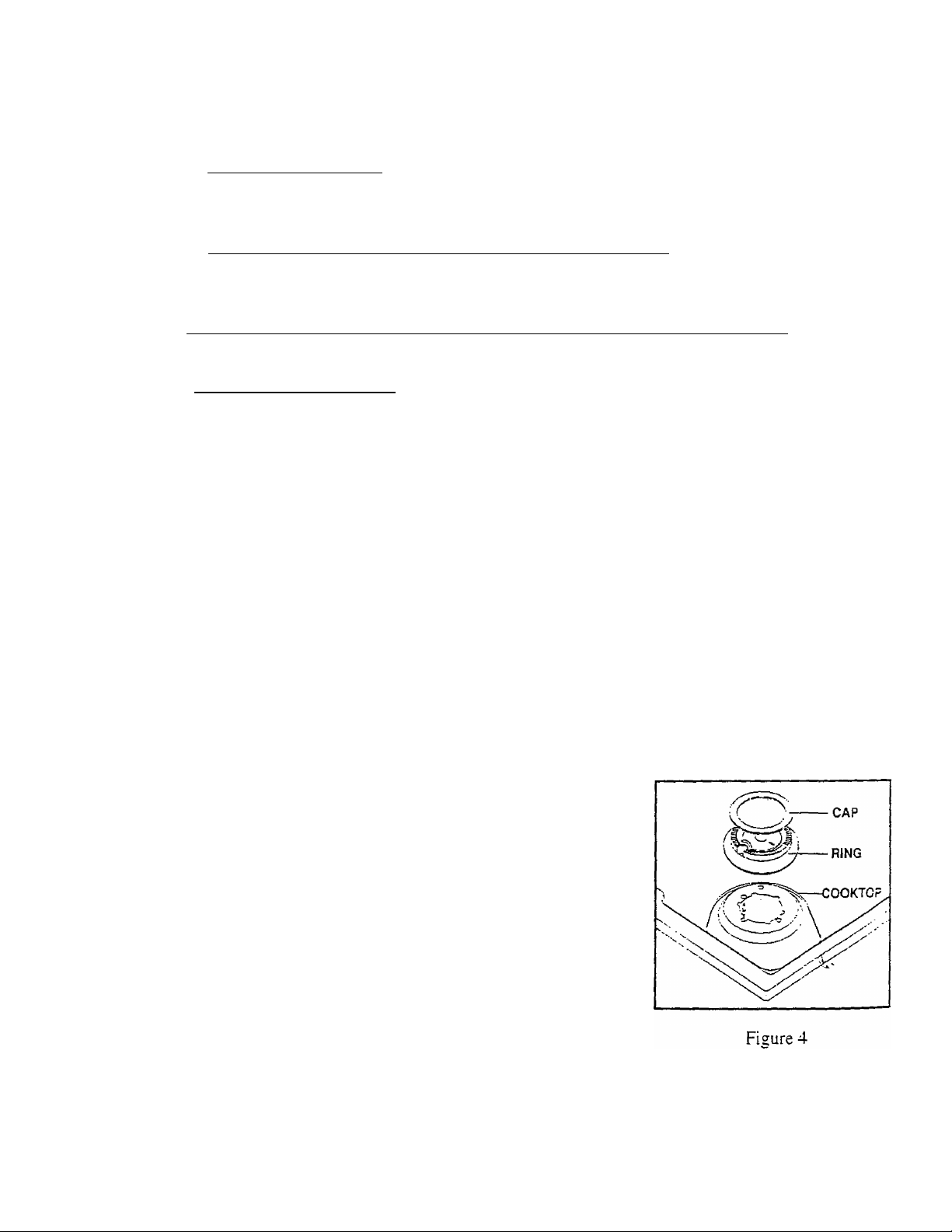
• First, the surface burners must be installed correctly, as seen in Figure 5.
• The ring and its cap must be in its place. The burners should be level with the surface of
the main top.
• The cookware supports must be in their places on the cook top. These plastic rings are
already in place and are used to prevent rocking as shown in Figure 6. Use stable
cookware with a fiat bottom and always place the utensils on the cookware supports before
lighting the burner.
• The surface burners are controlled by knobs located on control panel at front side of the
appliance, as seen in Figure 7.
• There is a symbol over the knob ofi the control panel to identify which knob controls which
burner. Also, there is a symbol indicator on the knobs, to aid in setting the burner to the
desired temperature.
10
r
l60n08SRO
Page 11

> To Light the Desired Surface Burner
• Push the control knob in.
• After the burner ignites, turn the knob counter-clockwise without releasing it to adjust the
flame size. Then release the knob.
• For maximum heat output, align the large flame symbol on the knob with the vertical line
on the control panel. In order to decrease the heat output, turn the knob in the direction of
the small flame symbol. For minimum heat output, align the small flame symbol on the
knob with the vertical line on the control panel.
• The amount of food being cooked, the amount of liquid, or the size of the pan should
determine the heat settings. Always position the utensil on the burner grate before
lighting the burner. For your safety, the flame should not extend beyond the sides of the
pan. Any flame larger than the bottom of the cookware is wasted and only heats the
handle.
• To turn the burner off. turn the knob clockwise until it reaches the (•) symbol.
• Before lighting a burner.
• Make sure all grates on the range are in place before using any.burner.
• After the burner ignites, turn the knob to adjust the flame size.' Watch the flame not the
knob, as you adjust the heat.
• In case of power failure.
• You can light the surface burners on your range with a match. Hold a lighted match to
the burner, and then turn the knob to the ON position. Use extreme caution when
lighting burners in this manner.
• Surface burners in use when an electrical power failure occurs will continue to operate
normally.
NOTE: The electrode of the spark igniter is exposed. When one burner is turned to ON, ail the
burners spark. Do not disassemble or clean around any burner while another burner is on. An
electric shock may result, which could cause you to knock over hot cookware.
Operating Your Oven Burner
• The oven is controlled by a knob located at left side of control panel. (See Figures 7 & 8)
• This knob has two functions.
■ To control oven burner.
» To control broiling burner.
• When the knob is turned in a counterclockwise direction, it controls the oven. When the
knob is turned in the clockwise direction, the broiler is engaged. Those burners do not
run simultaneously.
• The oven burner is controlled by a thermostat and has a flame failure device. The
numbers on the knob indicate the temperature in the center of oven cavity in degrees of
Fahrenheit.
. A WARNING S- The maximum amount of weight placed on to the oven shelf must not exceed 30 lbs.
11
15011C8&R0
Page 12

> Using Your Oven
• Open oven door to confirm nothing is stored in oven cavity and set racks to proper height.
• Push the oven knob in and turn it counter-clockwise to the desired temperature.
• Observe that the oven burner is lit. Wait for ten seconds for the heating of flame failure
device, then release the knob. Never pull up or out the bottom panel of the oven for
observation or operation of oven. Always make use of slots on the bottom panel of oven
for observation.
• It is usually necessary to preheat the oven. Close the oven door and wait for 10*20
minutes depending on desired temperature, then place food in the oven.
• When selected temperature is reached, the burner will maintain it.
• Do not forget that because the heat rises, the top of oven will always be hotter than the
bottom.
• After cooking time elapses, remove food and turn oven knob to OFF position, until you
hear a second click.
> Oven Light
The switch located at the extreme left of the control pane! turns the oven light on and off
(See Figure 7). When the button is depressed, the light will be on. (DG24CW / DG24CSS)
Using the Broiler tray
WRONG
Fi £ure 9
RIGHT
12
15O11C85;R0
Page 13

> operating Your Broiler Burner
The knob controlling the oven burner is also used for operating the broiler burner. (See Figure
9) When the knob is turned in clockwise direction, it controls the broiler.
When the knob is turned in the counter-clockwise direction, the oven is engaged.
Those burners do not run simultaneously. The broiling burner has one position. It is full on. The
burner cannot be set to other heat outputs.
To operate the broiler burner:
• Open oven door to confirm nothing is stored in oven cavity.
• Place food on a cold ungreased broiling pan and set rack to proper height.
A WARNING
The maximum amount of weight placed on to the
oven shelf must not exceed 30 lbs.
• Close the oven door.
• Push the oven knob forward. Ignition starts.
• Turn it in the clockwise direction to BROIL position without releasing the knob.
• Observe that the broiler burner is lit. Wait for ten seconds for the heating of flame failure
device, then release the knob.
• Broiling does not require preheating.
• All food should be turned at least once.
• When the food is cooked enough, remove the food and turn the knob to 'OFF' position.
CARE AND MAINTENANCE
The appliance should be cleaned regularly for long-term operating.
Make sure that all parts of the range are coo! before cleaning.
^ Removing the Oven Door for Cleaning
• Open the door fully.
• There is a small ring on each hinge. Pull the ring over the
claw-like hook, which is part of the hinge mechanism. Do
not forget to do this on both hinges before the next step.
(See Figure 10)
• Raise the door slightly and pull it straight out and away
from the oven. The door will come completely off.
• When replacing the door, locate it back g]to the hinge holes. Figure
Puli it down fully and slip the rings off the claw-like hooks.
• Close the door and make sure that it sits in place fully. If not, repeat all above steps. 'L'
^ Cleaning Your Oven
The oven door glass (G24CW and DG24CSS) should be cleaned regularly with a non-abrasive
liquid cleaner. Rinse with a damp cloth and then a dry one. The enameled and metal parts of
the oven should be cleaned with hot water and suitable liquid enamel cleaner.
Do not use harsh abrasive cleaners on the enameled panels.
13
160T1C85.ro
Page 14

^ Cleaning the Knobs and Control Panel
• Pull forward on the knobs to remove them.
• Wash in a water solution with a mild detergent mix. Do not use an abrasive cleaner or abrasive
action. Abrasive action will scratch away the knob markings.
• The control panel should be cleaned by using a damp cloth with mild detergent. Never rinse with
an abrasive cleaner or use abrasive action.
^ Cleaning the Cooking Supports. Cook top, Backauard and Surface Burners
• Utensil supports are made of enamel-coated steel.
• They can be cleaned at the sink with detergent or soap-filled scouring pads. They can also be put
in a dishwasher.
• The cooktop and backguard are also made of enamel-coated steel. They should be cleaned with
hot water and suitable liquid enamel cleaner.
• The aluminum burner rings may be damaged if soaked or put into a dishwasher. They should be
washed with a fine soapy wire wool.
• The burner caps are made of enameled sheet. It can be cleaned in the same manner as utensil
supports. It is very important that the burner is dry before replacing it in the range. A wet burner
will not allow the gas to ignite piroperly.
HELPFUL HINTS.,.
Aluminum; Medium-weight cookware is recommended because it heats quickly and evenly. Most foods,
brown evenly in an aluminum skillet. Use saucepans with tight-fitting lids when cooking with minimum
amounts of water.
Cast-iron: If heated slowly, most skillets will give satisfactory results.
Enameiware: Under some conditions, the enamel of some cookware may melt,
manufacturer's recommendations for cooking methods.
Glass: There are two types of glass cookware - those for oven use only and those for top-of-range
cooking (saucepans, coffee and teapots).
Heatproof Glass Ceramic; Can be used for either surface or oven cooking. It conducts heat very slowly
and cools very slowly. Check cookware manufacturer's direction to be sure it can be used on gas ranges.
Stainless Steel: This metal alone has poor heating properties and is usually combined wjth copper,
aluminum or other metals for improved heat distribution. Combination metal skillets generally work
satisfactorily if used at medium heat as the manufacturer recommends.
Stove top grills: Do not use stove top grills on your sealed gas burners. If you use the stove top grill on
the sealed gas burner it will cause incomplete combustion and can result in exposure to carbon monoxide
levels above allowable current standards. This can be hazardous to your health.
f
Follow cookware
к
Preheat the oven if the recipe calls for it. Preheat means bringing the oven up to the specified
temperature before putting the food in the oven. To preheat, set the oven at the correct temperature .(о/
10-20 minutes- selecting a higher temperature does not shorten preheat time. Preheating is necessa^
for good results when baking cakes, cookies, pastry, and breads. For most casseroles and roasts,
preheating is not necessary.
14
i6oncasRO
Page 15

You can solve many common appliance problems easily, saving you the cost of a possible service call.
■ Try the suggestions below to see if you can solve the problem before calling the servicer.
FIND YOUR
PROBLEM HERE
Surface burners do not light.
Flame burns halfway round.
Flame is orange.
Oven light does not work.
Oven or broiler does not heat.
Oven temperature is
inaccurate.
Nuisance sparking while oven
is in operation.
Oven burner cycles on and off.
Smoke or odor on initial oven
operation.
Range is not level.
PROBLEMS WITH YOUR APPLIANCE?
TROUBLESHOOTING GUIDE
POSSIBLE CAUSE
Surface control has not been
completely turned to the ON position.
Burner ports are clogged.
Burners not positioned properly.
V Range not set for appropriate gas
input.
V Pilot lights won't light due to power
failure.
Range power cord is disconnected
from the outlet.
❖ Burner ports are dogged. Use a small gauge wire or needle to open ports.
Moisture is present after cleaning. ❖ Lightly fan the flame and allow burner to operate until
Range is not set for appropriate gas
input.
❖ Dust particles in main line.
Range is not set for appropriate gas
input.
•:* Burned out or loose bulb.
Range is not set for appropriate gas
input.
Temperature control not set properly.
<• Pilot light will not light due to power
failure.
House fuse has blown or circuit
breaker has tripped.
Range cord is disconnected from
outlet.
V Oven capillary bulb not positioned
properly.
<* Temperature control not set properly.
Improper use of foil.
*:• Vent blocked.
Range not set for appropriate gas
incut.
Improperly grounded or reversed
polarity electrical outlet.
This is normal.
•:* This is normal. ■ •
't- Poor instatiation.
Weak or unstable floor.
V Push in and turn control to the ON position until burner
ignites, then turn control to desired flame setting.
Use a small gauge wire or needle to open ports.
Verify that the burners are positioned properly on the
orifice hoods and the burners are sitting flat on the burner
supponwith tabs engaged in slots.
❖ See range conversion section of this manual
•> Light pilots manually.
*> Be sure power cord is plugged into grounded outlet.
flame is full. OR dry burners thoroughly following
instructions in range ’Cleaning’ section.
*:* See range conversion section of this manual.
•> Allow burner to operate for a few minutes until flame turns
blue.
•> See range conversion section of this manual.
Tighten or replace oven :icht bulb.
See range conversion section of this manual.
❖ Make sure temperature control is set at desired
temperature.
❖ Light pilots manually.
•I* Check/reset circuit breaker and/or replace fuse. Do not
increase fuse capacity. If the problem is a circuit
overload, have it corrected by a qualified electrician.
<* Be sure the power cord is plugged into a grounded outlet
Verify that capillar/ bulb is snapped in clips straight 3"c
not touching sides or coated with oven cleaner or focc
❖ Make sure the temperature control knob is set a: t.ne
desired temperature.
•:* Keep foil clear of holes :n oven bottom anc off of even
racks.
f Keep vent at rear of backguard dear.
❖ See range conversion section in this manual.
•> Have outlet corrected cy a qualified electrician.
Place oven rack in center of oven. Place a.'Jeyel on :ne i
rack. Aejust leveling legs. ^ j
Be sure floor is level and can adequately support range ;
Contact carpenter to correct sagging or sloping floor, j
HOW TO FIX IT
i
1
Oven smokes excessively.
______________________
Kitchen cabinet misalignment may
make range appear to be unlevel.
Meat too close to broiler burner.
Meat not prepared properly.
15
Be sure cabinets are square and have sufficient room for |
range clearance. Contact cabinetmaker to correct |
problem. !
•> Reposition the broiler pan to provide more clearance !
between the meat and the oroiler burner !
Remove excess fat from meat. |
16C":25.R0
Page 16

SERVICE FOR YOUR GAS RANGE
We are proud of our customer service organization and the network of professional service
technicians that provide service on your Avanti appliances. With the purchase of your Avanti
appliance, you can have the confidence that if you ever need additional information or
assistance, the Avanti Products Customer Service team will be here for you. Just call us toll-
free.
AVANTI PRODUCTS CUSTOMER SERVICES
Product information
800-323-5029
Part Orders
800-220-5570
In-Home Repair Service
800-220-5570
Whatever your questions are about our
products, help is available.
You may order parts and accessories that
will be delivered directly to your home.
You may order these items by personal
check, money order, Master Card, or Visa.
An Avanti Products authorized service
center will provide expert repair service,
scheduled at a time that is convenient for
you. Our trained Servicers know your
appliance inside and out.
16
150110ebRO
Page 17

WARRANTY - GAS RANGE
LENGTH OF WARRANTY
FULL ONE-YEAR WARRANTY FROM
DATE OF PURCHASE ON ALL PARTS
EXCEPT GLASS PARTS
WE WILL PAY FOR
REPLACEMENT PARTS AND REPAIR
LABOR TO CORRECT DEFECTS IN
MATERIALS OR WORKMANSHIP.
SERVICE MUST BE PROVIDED BY AN
AUTHORIZED SERVICE COMPANY.
FULL 30-DAY WARRANTY FROM DATE
OF PURCHASE ON GLASS PARTS AND
FINISH OF PORCELAIN ENAMEL,
PAINTED OR BRIGHT METAL FINISHED
PARTS
WE WILL NOT PAY FOR
A. Service calls to;
1. Correct the installation of your range.
2. Instruct you how to use your range.
3. Replace house fuses or correct house wiring.
4. Replace owner-accessible light bulbs.
B. Pickup and delivery. Your range is designed to be repaired in the home.
C. Damage to your range caused by accident, misuse, fire, flood, acts of God, or use of products not
mentioned in this manual.
D. Repairs to parts or systems caused as a result of unauthorized modifications made to the
appliance.
E. Repairs when your range is used in other than normal, single-family household use.
REPLACEMENT PARTS AND REPAIR
LABOR TO CORRECT DEFECTS IN
MATERIAL OR WORKMANSHIP. SERVICE
MUST BE PROVIDED BY AN AUTHORIZED
SERVICE COMPANY.
_____________
AVANTl PRODUCTS SHALL NOT BE LIABLE FOR INCIDENTAL OR CONSEQUENTIAL
DAMAGES.
Some states do not allow the exclusion or limitation of incidental or consequential damages, so
this exclusion or limitation may not apply to you. This warranty gives you specific legal rights,
and you may also have other rights that vary from state to state.
This warranty is not valid outside the Continental United States.
17
:5O11C85iR0
Page 18

HELP US HELP YOU...
Read this guide carefully.
It is intended to help you operate and
maintain your new gas range properly.
Keep it handy to answer your questions.
If you don't understand something or you
need more help, please call:
Avanti Customer Service
800-220-5570
Keep proof of original purchase date (such
as your sales slip) with this guide to
establish the warranty period.
Write down the model and serial
numbers.
You'll find them on a plate located on the
left wail inside the gas range.
Please write these numbers here:
Date of Purchase
Mode! Number
Serial Number
Use these numbers in any correspondence
or service calls concerning your gas range.
If you received a damaged gas range,
immediately contact the dealer (or builder)
that sold you the gas range.
IF YOU NEED SERVICE f
We’re proud of our service and want you to
be pleased. If for some reason you are not
happy with the service you receive, here are
some steps to follow for further help.
FIRST, contact the people who serviced
your appliance. Explain why you are not
pleased, in most cases, this will solve the
problem.
Save time and money. Before you call for
service, check the Trouble Shooting Guide.
It lists causes of minor operating problems
that you can correct yourself.
NEXT, if you are still not pleased, write all
the details, including your telephone
number, to:
Customer Service
Avanti Products
10880 NW 30 Street
Miami, FL 33172
18
;3C1-:c0S;ro
Page 19

Installation Instructions
These instaictions are intended for a qualified installer only.
Converting Gas Type
This range arrives from factory, adjusted for use with Natural Gas. The setting is
indicated on the nameplate. It is important that the range is converted, if the factory
adjusted gas type is not desired.
To avoid electric shock that can cause personal injury or death, disconnect the appliance
from the electric outlet before servicing.
> Converting Pressure Regulator
The gas pressure regulator must be set for the
type of gas being used. The inlet pressure of the
gas supply shall be in accordance with the
nominal inlet pressure of the regulator used on
the range or 1/2 psi (3.5 kPa) pressure
maximum. On the factory setting for Natural Gas
operation, the pressure regulator will regulate the
pressure to 6 inches water column pressure.
When set for LP-Propane gas operation, it will
regulate the pressure to 10 inches water column
pressure.
To change the pressure regulator setting;
• Unplug the main supply cord of the range.
• Unscrew the cap on the pressure regulator
• Lift out cap and turn it over. If set for LP-Propane gas operation, the cap
must show ”LP”. if set for Natural Gas operation, the cap must show none.
• Place the cap on pressure regulator and tighten. (See Figure 1)
Figure I
Conversion of Burner Valves
• Unplug the main supply cord of the range.
• Remove burner control knobs from range by
pulling them out.
• Remove the screws on the front surface of ^
control panel.
• Remove two screws located on the bottom
surface of control panel.
• Pull out the control panel. .
• Using a small screwdriver, loosen or tighten
the screws located on each valve. If set for
LP-Propane gas operation, the screws must
be tightened fully. In the factory setting for
Natural Gas operation, the screws must be
loosened by turning them counterclockwise
• 3/4 turn.
• Replace the control panel and screws.
• Replace the control knobs. (See Figure 2)
Page 20

Converting Surface Burners
• Unplug the main supply cord of the range.
• Remove the rings of surface burners.
• Pul! up the burner rings with their caps and unscrew the orifices
using a 7mm-spanner socket.(See Figure 3)
• Use orifices located on the information card in a plastic bag at
lower rear side of the range. In order to choose the required
orifice for particular burner and gas type; see the mark located
on orifices and look at the information card.
• Screw each orifice to proper matching burner.
• Place the burner rings to their original locations. Be careful that
the burner rings are level with the surface of the main top.
• Keep the remaining orifices in their plastic bag for future use. (See Figure 3 and
Table 1)
BURNERS LP GAS ■ NATURAL GAS
RAPID 0.92
SEMI-rapid"
SIMMER
OVEN 0.90 1.32
BROILER*
Table 1 - Marks on orifices
0.65
0.50
0.90 1.32
1.40
0.97
0.75
Figure 3
Conversion of Oven Burner
• Unplug the main supply cord of the range.
• Open oven door.
• Remove the bottom panel of oven. Do this by pushing it backwards, then lifting the
front edge up and out as shown in Figure 4.
• Undo the screw, which holds the burner in place, and remove the burner
completely. (See figure 5)
• Loosen and remove the orifice at the bottom rear of oven. Using a
7mm-spanner socket. Replace the orifice supplied with the range.
For the mark of orifice, see Table 1.
• Loosen the retaining screw on the burner ring., If setting for LP-Propane gas
operation, slide the ring towards the burner to open the burner hole completely. In
the factory setting for Natural Gas operation, the ring must be located in a place
that maintains a gap of 1/6”. (See Figure 6)
• Replace the burner in the oven and replace the screw. Replace the bottom panel
of oven.
• Keep the remaining orifice in its plastic bag for future use.
Fieure 4
Figure 5
NG
Figure 6
Figure 7
1601107SRO
Page 21

Converting of Broiling Burner
• Unplug the main supply cord of the range.
• Remove the screw and washer holding the burner in place (See Figure 7).
• Pul) out the burner until it releases.
• Remove the orifice using a 7mm~spanner socket. Replace the orifice supplied with the
range. For the mark of orifice, see Table 1.
• Replace the burner and the guard in the oven. Replace the washer and tighten the screw.
Be sure that the guard sits completely in place while doing this.
• Keep the remaining orifice in its plastic bag for future use.
negulatof
Figure 8
> Gas Connection
Gas connection must be made in accordance with local codes
or in absence of local codes, with the National Fuel Gas Code,
ANSI Z223.1-Latest Edition.
Connect gas supply to regulator using a flexible connector, as
shown in Figure 8. Pressure regulator supplied with this range
has a 1/2-inch NPT female connection.
A manual shutoff, not supplied with this range, must be
installed In an accessible location outside of the range.
Use joint compound that is resistant to action of natural or
propane gas on all mate pipe threads.
Use supplied pressure regulator only.
Do not over tighten gas fitting when attaching to pressure
regulator. Over tightening may crack regulator.
Appliance and individual shutoff valve must be disconnected
from the gas supply piping system during any pressure testing
of that system at test pressures in excess of 1/2 psi (3.5 kPa).
Appliance must be isolated from gas supply piping system by loosening manual shutoff
valve during any pressure testing of the gas supply piping system at test pressures equal
to or less than 1/2 psi (3.5 kPa).
Gas supply pressure for checking regulator setting must be at least 1-inch water column
above manifold pressure shown on nameplate.
After final gas connection is made, turn on manual gas valve and test all connections in
gas supply piping and range for gas leaks.
In order to avoid property damage or serious personal injury, never use a lighted match.
If a leak is present, tighten joint or unscrew, apply more joint compound, tighten again
and retest connection for leak.
Adaptor
------
Fl«xibl»
3.'4" ServicB
Pipe Stub
Conn«ctOf
Adaptor
V
. || UmuM
, ) ähul 9tt
■ j Vitv.
> Electrical Connection
• Electrical connection must be made in accordance with local codes or in absence of local
codes, with the National Electrical Code, ANSlINFPA No.70-Latest Edition.
• Connect the 2-prong supply cord to a 120-volt, 60 Hz, 2-prong wall receptacle.
• Electrical connection must not interfere with gas connection. (See “Before installation”
user's guide)
Warning \ ^
Improper use of the grounded plug can result in a risk of electrical shock. If the power cord is
damaged have it replaced by an authorized Avanti Products service center.
______________________
16011O75/RO
Page 22

> Mobile Home Installation
The installation of this range must conform with the Manufactured Home construction and Safety
Standard, Title 24 CFR, Part 3280 {formerly the Federal Standard for Mobile Home
Construction and Safety. Title 24, HUD (Part 280)} or, when such standard is not
applicable, the Standard for Manufactured Home Installations, ANSI A 225.1 and
Manufactured Home Installations, Sites, and Communities ANSI/NFPA 501 A, or with
local codes.
When this range is installed in a mobile home, it must be secured to the floor during
transit. Any method of securing the range is adequate as tong as it conforms to the
standards listed above.
Copies of the standards may be obtained from:
‘National Fire Protection Association
Batterymarch Park
Quincy, MA 02269
‘American Gas Association
1515 Wilson Blvd.
Arlington, VA 22209
i6oiio7ano
Page 23

-V,
i £
Page 24

Page 25

80
79
Page 26

Spare Part List
page:
1 / 2
Cus comer
Customer Product Code
Product Code
Description
Exploded Drawing No
Revision
Valid Thru
Code
No
01999E01
1
02494S01
2
03100E11
3
03786H01
4
03303T01
5
04024T01
6
7 05010104
05040102 TFG\TFB\TFT LEVELING FOOT (SLACK)
8
05052506
9
05052510 CABLE PROTECTOR
10
05072513
11
05081005 TFB/TFG/TFR HICROSWITCH STOPPER
12
05096108
13
14
05096118 INNER GLASS SEAL
15
07011T01
16 07Q12T01
03117P TF321 OUTER CABINET BACK COVER
17
18
09767T01
09821T01
19
10016H01
20
21 10026T01
10160404
22
10170157 SPARKING PLUG WITH CABLE,440MM
23
24 10170158
10170206 SPARKING PLUG CABLE,1250MM
25
10170207 SPARKING PLUG CABLE,400MM
26
27 11010156
23
11010157
29 11010153
30 11010313
11010314
31
32
11010401
33 11010402
34 11010410
35 11010423 M6*0.75-0.90 INJECTOR r
35 11020728
37 11021314
38
11030413 TFG/B OVEN BURNER GAS DELIVERY PIPE PCS
39 11040503
40
11040504
41 11040507
42 11040503
43 11055132
44
11057132 OVEN BURNER .ADAPTOR
45 11060140 LARGE BURNER LOWER PART, .AESTHETIC
46 11061097 MEDIUM BURNER LOWER PART,AEST.HETIC
47
11062075
48 11273E11 TFG/B/R21 INNER OVEN BOTTOM COVER PCS
49 11560E11
50
51 12070C TFA-TFB INNER GLASS ASSEMBLY ELEMENT PCS
52
53
54
55
56
12020P
12143X01
12144T01
122S9P
12273P
12279?
Description Unit Quantity
TF3 4G USA PLATE
TFB21USA040 AVANTI CONTROL PANEL
TFB OVEN DOOR
TFG NARROW TYPE DRAWER BODY,WHITE PCS
TFB WIDE TYPE DRAWER COVER PCS
TFB/TFA LOWER STRIP FOR GLASS
TFG/TFB/TFA BUMPER FOR HANDLE
STRAIN RELIEF PCS
COOKING GRID PLUG
TFB OVEN DOOR SEALING
TFS-TFG OUTER CABINET RIGHT SIDE PANEL
TFB-TFG OUTER CABINET LEFT SIDE PANEL
TFB SUPPLEMENT BOTTOM PLINTH
TFB BASEMENT FRONT/ REAR ELEMENT
ANTI TIP BRACKET
TFA/B ALUMINIUM HANDLE
IGNITER
SPARKING PLUG WITH CABLS,200MM
LARGE BURNER UPPER PART {AESTHETIC/WITH
IGNITER)
MEDIUM BURNER UPPER PART (AESTHETIC/WITH
IGNITER)
SMALL BURNER UPPER PART (AESTHETIC/WITH
IGNITER)
TFG/TFB/TFR21 GRILL BURNER REFLECTOR
TFG/B21 GRILL BURNER GROUP(USA)
M5*0.75-0*50 INJECTOR
M6’'0.75-0.65 INJECTOR
MS'0.75-0.92 INJECTOR
OVEN&GRILL BURNER THERMOSTAT
TAP WITH THERMOSTAT(NG, GREEN PAINTED)
MALE NUT
CLAMPING .RING
CLAMPING RING
MALE NUT
TFG GRILL BURNER ADAPTOR(NG)
NEW AESTHETIC SMALL BUHNER LOWER PART
TFB21 INNER OVEN(USA)
TFG-TFB IGNITION SUPPORT ELEMENT PCS
TFG/3/U PLATE SUPPORT ELEMENT,RIGHT PCS
TFG/3/U PLATE SUPPORT ELEMENT,LEFT
TFG/B/R21 GRILL BURNER HEAT P.ROTECTOR
TFA/B/G/U HINGE SUPPORT ELEMENT,RIGHT
TFA/S/G/U HINGE SUPPORT ELEMENT.LEFT
AVANTI
DG2-ICW
TEB21USA04
U JQN 2000
PCS 1
PCS 1
PCS
PCS
PCS
PCS
PCS •
PCS .
PCS
PCS
PCS
PCS
PCS
PCS
PCS
PCS
PCS
PCS
PCS
PCS
PCS
PCS
PCS
PCS
PCS
PCS
PCS
PCS
PCS
PCS
PCS
PCS
PCS
PCS
PCS
PCS
PCS
PCS
PCS
PCS
PCS
PCS
PCS
PCS
PCS
PCS
PCS
PCS
1
1
1
1
2
4
1
1
4
4
1
1
1
1
1
1
2
1
1
1
2
2
1
1
1
2
1
1
1
1
2
1
2
1
1
1
4
4
3
2
1
1
2
1
1
1
1
2
1
1
1
1
1
Page 27

spare Part List
page;
2 / 2
Customer
Customer Product Code
Product Code
Description
Exploded Drawing No
Revision
Valid Thru
No Code
57 12756H07 TF3 DRAWER GUIDE WITH CONSOLE,RIGHT
58 12756H08
59 13010251
60 13010835
61 14520105 TFG/3/A KNOB SPRING
62 14560101 CLIP
63 14550103 THERMOSTAT CLIP
64 14560106
14560107
65
66 15050283 TFB BOTTOM STYRAPHOR
67
15050349
68 15050350 TFB/G SPLASH guard FRONT STYRAPHOR
69 15050353
70 15050354 TF3/G LEFT FRONT STYRAPHOR
71
15050360
72
15Q51E11
15062S11
73
74 15759501 ТГЗ SPLASH PLINTH (USA)
75 16011075
7 6 16011085 TFa2IUSA03/04/06AVANTI INSTRUCTION MANUAL
77 1504 1567
78 16041558
15099K53 SOURDILLION HOB TAP KNOB(PROFILE TYPE)
79
155 07N
80
81 17C10136 TF3/A INNER GRID
32 17020220
17098E11
83
84
17099211
17107211
85
17405N
86
17674N
87
88
90
91
94 18010206
95
96 23424519
97
98
99 6005:201
101 600-1401 TFG21 INNER ILLUMINATION BUTTON,PUSH ON-PUSH
17579N
17530N TF3 FRONT LEFT GAS DELIVERY PIPE PCS
89
1753 IN TFB FRONT RIGHT GAS DELIVERY PIPS PCS
17 5 52N
92 17592K01
93 i8o:o:oi
13755H02 TERMINAL BLOCK (1000 DS\3)
25004H73
60015408
100
60054303
Description
ТГЗ DRAWER GUIDE WITH CONSOLE,LEFT
TFS/G/A INNER GLASS LOW-E
TF3 I SOX GLASS PCS
MICRO SWITCH SPRING PCS
SEGMENT OF SPARKING PLUG
TFB/G SPLASH GUARD REAR STYRAPHOR PCS
TF3/G RIGHT SACK STYRAPHOR PCS
ТГЗ PLATE STYRFOR
TFG/3 OUTER TRAY PCS
TFG/B/A INKER TRAY
TFG21 INSTRUCTION MANUAL
TF3/G LOWER PART OF OVEN KNOB,WHITE PCS
TF3/G LOWER PART OF HOB KNOB PCS
OVEN TAP KNOB
TFB TWIN COOKING GRID
MEDIUM BURNER COVER (AESTHETIC)
SMALL BURNER COVER (AESTHETIC)
BIG BURNER COVER
TF321 GAS DELIVERY PIPE
TFG-321 GRILL BURNER GAS DELIVERY PIPE
ГГ5 SACK LEFT GAS DELIVERY PIPE
TFB BACK RIGHT GAS DELIVERY PIPS
TF3.'G/R OVEN BURNER GROUP PCS
TF3-TFG WIRE RACK SYSTEM FIXING NUT PCS
TF321 SPLASH PLINTH BACK COVER PCS
TF321USA04 AVANTI BOX
TF321 HIRING TREE PCS
POWER SUPPLY CORD PCS
OVEN LAMP,T300,15W,120-.130V
TOA41 MICRO SWITCH PCS
:AVANTI
:DG24CW
:TFB21USA04
:14 JUN 2000
Unit
PCS
PCS
PCS
PCS
PCS
PCS
PCS
PCS
PCS
PCS
PCS
PCS
PCS
PCS
PCS
PCS
PCS
PCS
PCS
PCS
PCS
PCS
PCS
PCS
PCS
PCS
PCS
PCS
PCS
PCS
Quantity
i.
1
1
1
1
5
1
2
4
3
1
1
1
1
1
1
1
1
1
1
1
1
4
4
1
i
2
2
1
1
1
1
1
1
1
1
2
1
I
1
1
1
1
4
1
6102:336 TF3.TFG/TFR 0.30 INJ. HOB TAP
102
61C 2 3 3 37 TF3.TFG/TFR 0.39 INJ. HOB TAP
103
6102:338
104
61021104 TFG21 GAS REGULATOR
105
61040603 LOWER SEAL FOR TAP (TFG/B/S)
106
68020107
107
108
68C20200
6302:300
109
TF3/TFG/TFR 0.45 INJ. HOB TAP
RIGHT HINGE PCS
LEFT HINGE
HINGE BUSHING PCS
PCS
PCS
PCS
PCS
PCS
PCS
L
2
1
1
4
1
1
2
Page 28

Warranty Information
Thank you for purchasing this fine Avanti product. Please fill out this card and return it within
■ 100 days of purchase and receive these
important benefits:
Confirm your warranty:
Your prompt product registration confirms your right to the protection available under the
terms and conditions of your Avanti warranty.
Protect your product:
We will keep the model number and date of purchase of your new Avanti product on file
to help you refer to this information in the event of an insurance claim such as fire or
theft.
■ Promote better products:
We value your input. Your responses will help us develop products designed to best
meet your future needs.
-(detach here)-
Avanti Registration Card
Name
Address
City
Area Code Phone Number
State
Zip
Did You Purchase An Additional Warranty:
□Extended GFood Loss DNone
Reason For Choosing This Avanti Product:
Please indicate the most important factors
that influenced your decision to purchase
this product.
□ Price
□Product Features
□Avanti Reputation
□Product Quality
□Salesperson Recommendation
□Friend/Relative Recommendation
□Warranty
□other
_______________
Model # Serial #
Date Purchased
Occupation
Store/Dealer Name
As Your Primary Residence. Do You:
□Own GRent
Your Age:
□uhder 18 □ 18-25 G26-30
□31-35 G36-50 GoverSO
Marital Status:
□Married GSingle
Is This Product Used In The:
□Home GBusiness
How Did You Learn About This Product;'
□Advertising
□in Store Demo
□other
Comments
_____
□Product Features
□Personal Demo
16020062/RO
 Loading...