

Page 1
^
-
-----------------------
ei_iTE
GAS RANGE
INSTRUCTION MANUAL
Model Number:
DG200W
DG240W
CAUTION:
BEFORE USE, PLEASE READ AND FOLLOW ALL SAFETY RULES AND OPERATING
INSTRUCTIONS.
Avanti has a policy of continuous improvement on its products and reserves the right to
change materials and specifications without notice.
Avanti Products, A Division of The Mackle Co., Inc.
P.O. Box 520604 - Miami, Florida 33152
www.avantiproducts.com
Page 2
WARNING
• ALL RANGES CAN TIP
• INJURY TO PERSON COULD RESULT
• INSTALL ANTI-TIP DEVICE PACKED
WITH RANGE
• SEE INSTALLATION INSTRUCTIONS
WARNING: IF THE INFORMATION IN THIS MANUAL IS NOT
FOLLOWED EXACTLY, A FIRE OR EXPLOSION MAY RESULT
CAUSING PROPERTY DAMAGE, PERSONAL INJURY, OR DEATH.
In theiyicinity. of this; Or a
Do npt;tiy tc);:ilght ^ ^
Do not tQU^^ rany aiectridai switch; do not use any phone in your
♦ Immodiiitpilv nail voEir n?iR siinnilfir from a neiQHbor’s phone.
a qualjfied installefi;
sen/ica' agendy, or the gaa supplien
Page 3

CONTENTS
TABLE OF CONTENTS
Parts & Features........................................................................................................... 4-5
Before Using Your Gas Range........................................................................................ 6
Precautions And Recommendations............................................................................ 7-8
How To Use Top Burners........................................................................................... 9-10
How To Use The Gas Oven..................................................................................... 11-14
Care And Maintenance............................................................................................. 15-17
Trouble Shooting Guide................................................................................................. 18
Service........................................................................................................................... 19
Warranty......................................................................................................................... 20
Page 4
PARTS & FEATURES
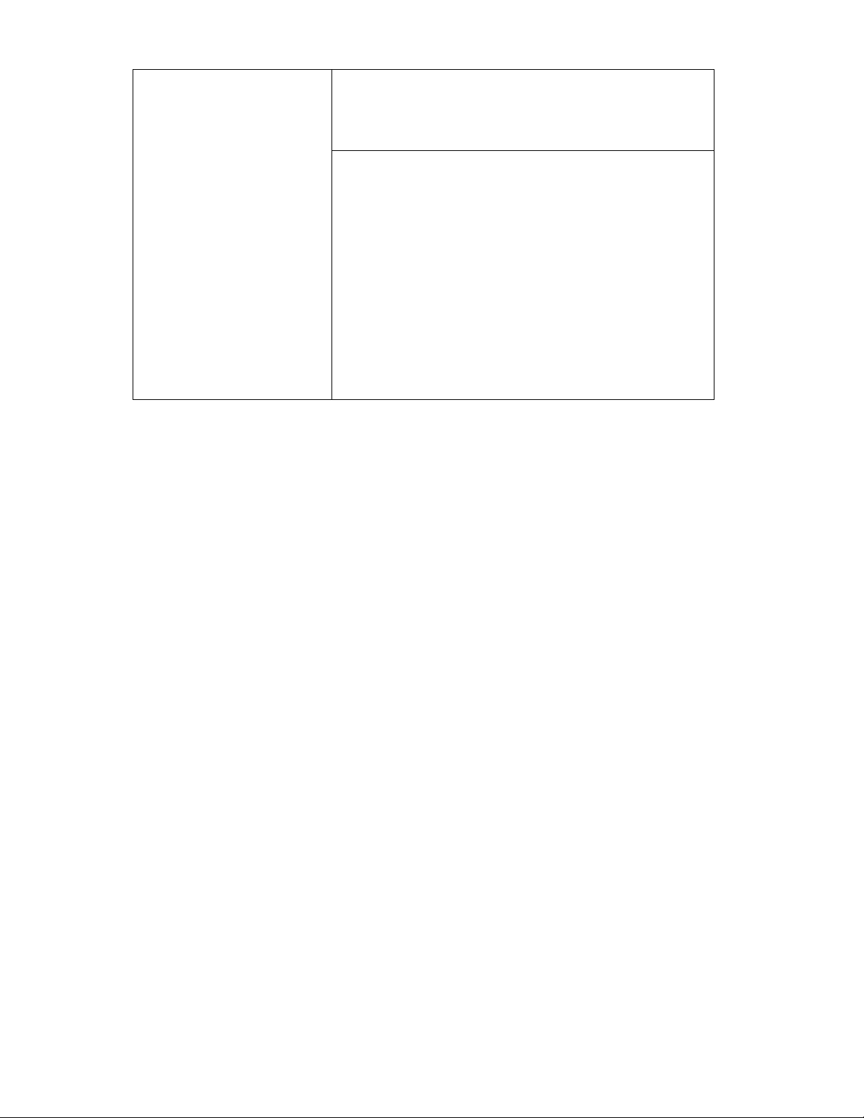
Figure 1
12 4
1. Cooktop
2. Control panel
3. Door handle
4. Oven light
5. Backguard
6. Leveling legs
7. Removable storage drawer
8. Rating plate
9. Oven vent
10. Glass oven door
11. Anti-tip bracket
12. Broil burner
13. Broiling pan
14. Oven shelves
15. Bake burner
Page 5
PARTS & FEATURES
COOKING HOB
1. Auxiliary burner (AUX) - 3500 BTU/hr
2. Left semi-rapid burner (SR) - 6000 BTU/hr
3. Right semi-rapid burner (SR) - 6000 BTU/hr
4. Rapid burner (R) - 10000 BTU/hr
Note:
- The electric gas-lighting device Is incorporated into the
knobs.
: CAUTION^
Lif .the;
Г;:ЙЙетрЬ^
piGasappilances; produce'heat: and: humid ity; in 1Ьё;ёрУ1гопт-;
rment iin!which- '' "T'iV.'.T';'!
i; ;Ёпзиге^^Ьа1ТЬе:;ср6к1пд::^егёёч
...............
......
^
___
at [thb icdritfol kriob laind. wait:: aL least i:: minute:! before
-,г. "vi-
:CAUTION:
,!паЙопё)Лоса!-с'оЬ .-Or-- - \ 7 .= 77:->7.
f= =m
■
у ::л :: -
77.: 7;::
Figure 2
• ■ , -. T . -:.Г:
(
VF7 771X v69i
77';;;7.;7-
■■ T'- ir.-
'77'7:77-::
7: :■ '
: ■ ;
Л " Л:7
■ .
Щх
7:7-'"!7:'77'
■■■:
7Ш7::77;-7
И;:4;
л
CONTROL PANEL
CONTROLS DESCRIPTION Cooking hob controls:
5. Front left burner (1) control knob
6. Rear left burner (2) control knob
7. Rear right burner (3) control knob oo
8. Front right burner (4) control knob
Oven controls:
9. Oven light push button
10. Gas oven/gas broil burner control knob
Ш:
ШМ:" э»\^^
.. 7 = Wj
oo
•o
•o
oo
oo
o«
Упя
Figure 3
Т?\ Ий'
ом^^Г7
Page 6

BEFORE USING YOUR GAS RANGE
WARNING!!
HAVE THIS RANGE INSTALLED BY A QUALIFIED INSTALLER.
Improper installation, adjustment, alteration, services, or maintenance can cause injury
or property damage. Consult a qualified installer, service agency, or the gas supplier.
Before Using Your Gas Range
/ Remove the exterior and interior packing.
/ Remove the protective film on steel and aluminium parts
/ Check to be sure you have all of the parts listed below:
• Orifice Packet
• Anti-tip bracket
• 4 leveling legs
• 2 cooking grids
• 4 caps and 4 bases in the burner assembly
• 5 burner knobs
• 1 push button
• Broiler Tray
/ Clean the interior surface with lukewarm water using a soft cloth.
/ Have the installer show you the location of the ranges gas shut-off valve and how to shut
it off if necessary.
/ Have your range installed and properly grounded by a qualified installer in accordance with
the Installation Instructions.
/ Do not attempt to repair or replace any part of your range unless it is specifically
. recommended in this manual.
/ Be sure your range is correctly adjusted by a qualified service technician or installer for the
type of gas (natural or LP) that is being used.
/ Do not remove permanently affixed labels, warnings, or plates from the product. This may
void the warranty.
/ The installer should leave these instructions with the consumer who should retain for local
inspector’s use and for future reference.
/ Please observe all local and national codes and ordinances.
: Th|s appliance is designedi and manufactured solely fori the cooking of domestic (house
hold) food arid 'is: not sujt^.le for any non domestic application and therefore should not;
; be used in'b eorrirnercial envirortmenLT ^ -r : - ; V; ;;;;:: :
rpnmeht; i.e. a samlibbrnme^^ Comrhunal environrpbht ’ ; ■
Read the instructions carefully before installing and using the appliance.
CAUTION: this appliance must only be installed in a permanently ventilated room in
compliance with the applicable regulations.
I It ;|s advised td I^Hbw these inMm
/ Clean the interior of the oven \with cloth soaked in water and detergent (neutral, then
diry;:c^efu!Îy.;:^
; ; / Furnish the interior of the oven by insert shelves and tray.:
/:-Turn.the even dn; to-the-maximum .teimperat^
; ; ■ - from the i oven burner. The same operation should be followed for broil burner, ^ : : ■
Page 7

PRECAUTIONS & RECOMMENDATIONS
IMPORTANT PRECAUTIONS AND RECOMMENDATIONS
After having unpacked the appliance, check to ensure that it is not damaged and that the
oven door closes correctly. In case of doubt, do not use it and consult your supplier or a
professionafly qualified technician.
Packing elements (i.e. plastic bags, polystyrene foam, nails, packing straps, etc.) should not
be left around within easy reach of children, as these may cause serious injuries.
The packaging material is recyclable and is marked with the recycling symbol ¿Ci.
/ Do not attempt to modify the technical characteristics of the appliance as this may cause
danger to users.
/ Do not carry out cleaning or maintenance operations on the appliance without having
previously disconnected it from the electric power supply.
/ If you should decide not to use this appliance any longer (or decide to substitute an older
model), before disposing of it, it is recommended that it be made inoperative in an appro
priate manner in accordance to health and environmental protection regulations, ensur
ing in particular that all potentially hazardous parts be made harmless, especially in rela
tion to children who could play with unused appliances.
Remove the door before disposal to prevent entrapment.
/ After use, ensure that the knobs are in OFF position.
/ Do not allow children or other unqualified people to use the appliance without your super
vision.
/ During and after use of the range, certain parts will become very hot. Do not touch hot
parts.
/ Keep children away from the range when it is in use.
/ Some appliances are supplied with a protective film on steel and aluminium parts. This
film must be removed before using the appliance.
/ Fire risk! Do not store flammable material in the oven or in the bottom drawer.
/ Make sure that electrical cables connecting other appliances in the proximity of the range
cannot come into contact with the hob or become entrapped in the oven door.
/ Do not line the oven walls top and bottom with aluminium foil. Do not place shelves, pans,
backing trays broil tray or other cooking utensils on the base of the oven chamber.
^ The manufacturer declines all liability for injury to persons or damage to property caused
by incorrect or improper use of the appliance.
/ To avoid any possible hazard, the appliance must be installed by qualified personnel only.
Any repairs by unqualified persons may result in electric shock or short circuit. In order to
avoid possible injuries to your body or to the appliance, do not attempt any repairs by
yourself. Such work should be carried out by qualified service personnel only.
^ Danger of burns! The oven and cooking accessories may become very hot during oper
ation. Make sure children are kept out of reach and warn them accordingly. To avoid burns
use kitchen clothes and gloves when handling hot parts or utensils.
/ Stand away from the range when opening oven door. Hot air or steam which escapes can
cause burns to hands, face, and/or eyes.
/ Never clean the oven with a high-pressure steam cleaning device, as it may provoke a
short circuit.
/ This appliance is intended for use in your household. Never use the appliance for any
other purpose!
IMPORTANT PRECAUTIONS AND RECOMMENDATIONS FOR USE OF ELECTRICAL APPLIANCES
Use of any electrical appliance implies the necessity to follow a series of fundamental rules.
In particular;
/■ Never touch the appliance with wet hands or feet;
/ Do not operate the appliance barefooted;
/ Do not allow children or disabled people to use the appliance without your supervision.
The manufacturer cannot be held responsible for any damages caused by improper, incorrect
or unreasonable use of the appliance.
Page 8

PRECAUTIONS & RECOMMENDATIONS
GENERAL INFORMATION
WARNING!!
1. This appliance shall not be used for space heating. This information is based on
safety considerations,
2. All openings in the wall behind the appliance and in the floor under the appliance
shall be sealed.
3. Keep appliance area clear and free from combustible materials, gasoline, and other
flammable vapors.
4. Do not obstruct the flow of combustion and ventilation air.
5. Disconnect the electrical supply to the appliance before servicing.
6. When removing appliance for cleaning and/or service;
A. Shut off gas at main supply.
B. Disconnect AC power supply,
C. Disconnect gas line to the inlet pipe.
D. Carefully remove the range by pulling outward.
CAUTION: Range is heavy; use care in handling.
7. The misuse of oven door (e.g. stepping, sitting, or leaning on them) can result in
potential hazards and/or injuries.
8. When installing or removing the range for service, a rolling lift jack should be used.
Do not push against any of the edges of the range in an attempt to slide it into
or out of the installation. Pushing or pulling a range {rather than using a lift jack)
also increases the possibility of bending the leg spindles or the internal coupling
connectors.
WARNING!!
ELECTRICAL GROUNDING INSTRUCTIONS
FOR PERSONAL SAFETY, THIS APPLIANCE MUST BE PROPERLY GROUNDED.
This appliance is equipped with a three-prong grounding plug for your protection
against shock hazard and should be plugged directly into a properly grounded socket.
Do not cut or remove the grounding prong from the plug.
Do not under any circumstances cut or remove the third (ground) prong from
the power plug.
Electrical installation should comply with national and local codes.
REPLACEMENT PARTS
Only authorized replacement parts may be used in performing service on the range.
Replacement parts are available from factory authorized parts distributors. Contact
the nearest AVANTI parts distributor in your area.
Page 9

HOW TO USE THE TOP BURNERS
GAS BURNERS
Gas flow to the burners is adjusted by turning the knobs which control the valves.
Turning the knob so that the indicator line points to the symbols printed on the panel
achieves the following functions:
Off = Closed valve
= maximum rate
LO = minimum rate
The maximum aperture position permits rapid boiling of liquids, whereas the minimum
aperture position allows simmer warming of food or maintaining boiling conditions of
liquids.
To reduce the gas flow to minimum, rotate the knob further anti-clockwise to point the
indicator towards the [Q position.
Other intermediate operating adjustments can be achieved by positioning the
indicator between the maximum and minimum aperture positions, and never between
the maximum aperture and Off positions.
=V;;i:W;BiWheh^thq:rariige;is;npibeihg!d^bdpetthe;:gasikn^
; ;and also olpse the ga^ ‘sh ut-bif-yaiydi placed: ph!theimain; gas aupiplyr line/i’
Figure 4
oo
•o
Off
LIGHTING GAS BURNERS
In order to light the burner, you must:
1 - Turn the knob in an anti-clockwise direction up to the ¿<f|| position (maximum
rate), push in and hold the knob until the flame has been lit.
The sparks produced by the lighter situated inside the relative burner will light the
flame.
In the event that the local gas supply conditions makes it difficult to light the burn
er in ixflj position, try again with the knob in [Q position.
If there is no mains electrical supply, bring a lighted match close to the burner.
2 - Adjust the gas valve to the desired position.
To re-light the burner, return the knob to the Off position and repeat the operations for
lighting.
TherangP bebomes vep/
; Keep children weli bjirt of
Figure 5
OFf
Page 10

Figure 6
HOW TO USE THE TOP BURNERS
CHOICE OF BURNER {fig. 6)
The symbols printed on the panel above the gas knobs indicate the correspondence
bet\ween the knob and the burner.
The most suitable burner is to be chosen according to the diameter and volume capac
ity of the container to be warmed.
It is important that the diameter of the pots or pans suitably match the heating poten
tial of the burners in order not to jeopardise the efficiency of the burners, bringing about
a waste of gas fuel.
A small diameter pot or pan placed on a large burner does not necessarily mean that
boiling conditions are reached quicker.
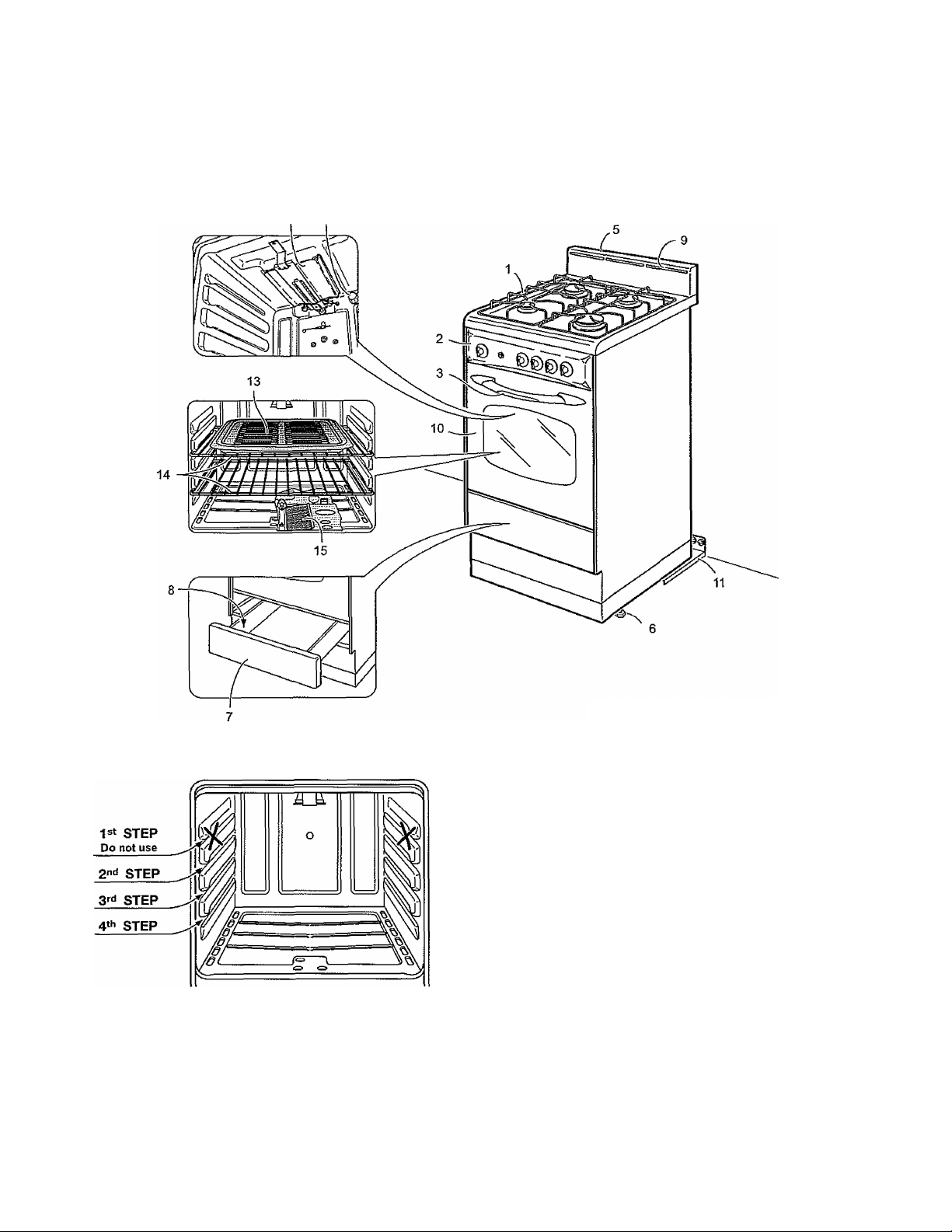
DIAMETERS OF PANS WHICH MAY BE USED ON THE TOP BURNERS
BURNER
Auxiliary
Semirapid 6“ 19/64 (16 cm)
Rapid 9" 7/16 (24 cm)
Do not use pans with concave or convex bases
MINIMUM MAXIMUM
4“ 23/32 (12 cm)
5" 1/2 (14 cm)
9" 7/16 (24 cm)
10" 15/64 (26 cm)
10
Figure 7
Make sure that the handles of cookware
do not stick out over the edge of the
range, to avoid them being knocked
over by accident. This also makes It
more difficult for children to reach the
cooking vessels.
Page 11

HOW TO USE THE GAS OVEN
GENERAL FEATURES
The gas oven is provided with two burners:
a) Oven burner, mounted on the lower part of the oven (12000 BTU/hr)
b) Broil burner, mounted on the upper part of the oven (8500 BTU/hr).
USING THE OVEN FOR THE FIRST TIME
It is advised to follow these instructions:
— Insert shelves and tray.
— Turn the oven on to the maximum temperature (position 550"*^) eliminate
possible traces of grease from the oven burner. The same operation should be
followed for broil burner (knob on position BROIL^.
— Switch off the electrical supply, let the oven cool down, then clean the interior
of the oven with cloth soaked in water and detergent (neutral) then dry carefully..
OVEN BURNER
It carries out normal “oven cooking".
The gas flow to the burner Is regulated by a thermostat which allow to maintain the oven
temperature constant.
The control of the temperature is assured by a thermostatic probe positioned inside the
oven.
The probe must be always kept in its housing, in a clean condition, as an incorrect posi
tion or encrustment may cause an alteration in the control of the temperature.
irAttentio'n
ye^ihqtrd urjn^^
■ijKeep^childrenia^
The door is; hot, use the handle.
VÉRYIMPQRTÁNT;^ ; ;
îàtwaYs;witti;Î^id
Figure 8
O
Off
OVEN THERMOSTAT
The numbers printed on the control panel (fig. 8) indicate the increasing oven tempera
ture value (“F). To regulate the temperature, set the chosen number onto the control
knob indicator.
The position BROIL* serves only to turn on the broil burner.
N.B. When the range ismpt being used;set the;gas knobs to their (Jff positions
aiidiajs№M^^liheiga^;shqt“Cpyalyei^laG^
GAS OVEN SETTING
Number printed
on the knob
Temperature
in “F
200
250
300
350
400
450
500
550
Corresponding
temperature
in X
93
121
149
177
204
232
260
288
11
Page 12

HOW TO USE THE GAS OVEN
Figure 9
Figure 10
IGNITION OF THE OVEN BURNER
The thermostat allows the automatic control of the temperature.
The gas delivery to the oven burner is controlled by a two way thermostatic tap (oven
and broil burners) with flame-failure device.
To light the oven burner operate as follows:
1) Open the oven door to its full extent.
WARNING: Risk of explosion! The oven door nrust be open during this opera
tion.
2) Lightly press and turn the thermostat knob anti-clockwise (fig, 9) to max position
550^
3) Press the knob right down to prime the electric ignition. Keep the knob pressed.
In case of power interuption, press the knob and immediately approach a lighted
match to the opening “A" (fig, 10).
Never continue this operation for more than 15 seconds. If the burner has still
not ignited, wait for about 1 minute prior to repeating the ignition.
4) Wait about 10/15 seconds after the burner lighting before releasing the knob (time of
priming of the valve).
5) Close the oven door slowly and adjust the burner according to the power required.
If the flame extinguishes for any reason, the safety valve will automatically shut off the
gas supply to the burner.
To re-light the burner, first turn the oven control knob to position Off , wait for at least
1 minute and then repeat the lighting procedure.
Attention: the oven door becomes very hot during operation,
keepchijdre^
OVEN COOKING
Before introducing the food, preheat the oven to the desired temperature.
For a correct preheating operation, it is advisable to remove the tray from the oven and
introduce it together with the food, when the oven has reached the desired temperature.
Check the cooking time and turn off the oven 5 minutes before the theoretical time to
recuperate the stored heat.
12
Page 13

HOW TO USE THE GAS OVEN
IGNITION OF THE BROIL BURNER
The broil burner generates the infra-red rays for broiling.
To light the broil burner operate as follow:
1 ) Open the oven door to the full extent.
WARNING: Risk of explosion! The oven door must be open during this
operation.
2) Lightly press and turn the thermostat knob clockwise to the BROIL* position
(fig. 11).
3) Press the knob right down to prime the electric ignition. Keep the knob pressed.
In case of power interuption, press the knob and put a lighted match to the right
and left side of the burner (fig. 12).
Never continue this operation for more than 15 seconds. If the burner has still
not ignited, wait for about 1 minute prior to repeating the ignition.
4) Wait about 10/15 seconds after the burner lighting before releasing the knob (time
of priming of the valve).
5) Close the oven door slowly.
If the flame extinguishes for any reason, the safety valve will automatically shut off the
gas supply to the burner.
To re-light the burner, first turn the oven control knob to position Off , wait for at least
1 minute and then repeat the lighting procedure.
: Attention :|th&ìoyen;fdp.iòin!^^^
rkeep children away. ^
Figure 11
Off
OVEN LIGHT
The range is equipped with a tight that illuminates the oven to enable visually controlling
the food that is cooking.
This light is controlled by a push button on the control pane) (Fig. 13).
Figure 13
13
Page 14

HOW TO USE THE GAS OVEN
Figure 14
Figure 15
BROILING
Very important: the broil burner must always be used with the oven door closed.
- Position the shelf on the second level from the top (fig. 14).
- Turn on the broil burner, as explained in the preceding paragraphs and let the broil
burner preheat for about 5 minutes with the door dosed.
- Place the food to be cooked above the broiling pan.
- introduce the broiling pan in the oven (fig. 15). The broiling pan should be placed
above the shelf and it should be centered with the broil burner (fig. 14).
Do not broil without using the broiling pan.
Important: Use always suitable protective gloves when inserting/removing the
broiling pan, shelves, pans on other cooking utensils from the oven.
Page 15

CARE & MAINTENANCE
Figure 18
À WARNING
tr
Electrical Shock Hazard
Plug into a grounded 3-prong
outlet,
Do not remove ground prong.
Do not use an adapter.
Failure to follow these instructions
can result in death, fire, or
electrical shock.
Figure 19
GENERAL RECOMANDATION
✓ Important; Before any operation of cleaning and maintenance disconnect the
appliance from the electrical supply.
/ It is advisable to clean when the appliance is cold and especially for cleaning the
enamelled parts.
/ Avoid leaving alkaline or acidic substances (lemon juice, vinegar, etc.) on the
surfaces.
/ Avoid using cleaning products with a chlorine or acidic base.
The oven must always be cleaned after every use. using suitable products and
keeping in mind that its operation for 3D minutes on the highest temperature
eliminates most grime reducing it to ashes.
ENAMELLED PARTS
/ All the enamelled parts must be cleaned with a sponge and soapy water only or
other non-abrasive products.
/ Dry preferably with a chamois leather.
If acid substances such as lemon juice, tomato conserve, vinegar etc. are left on
the enamel for a long time they will etch it, making it opaque.
STAINLESS STEEL ELEMENTS
/ Stainless steel parts must be rinsed with water and dried with a soft and clean
cloth or with a chamois leather.
/ For difficult dirt, use a specific non-abrasive product available commercially or a
little hot vinegar.
/ Note: regular use could cause discolouring around the burners, because of
the high flame temperature.
WARNING
VERY IMPORTANT
Before any operation of maintenance
disconnect the appliance from the
electrical mains supply.
Dp hbt "use ysteaifri jeti c
ibeciausé; tlipjyhunrd
; inlilti^te; ; intd i ïhe : appli^
it dangerous.
INSIDE OF OVEN
This must be cleaned regularly.
With the oven warm, wipe the inside walls with a cloth soaked in very hot soapy water
or another suitable product.
GAS VALVES
In the event of operating faults in the gas valves, call the Service Department.
REPLACING THE OVEN LIGHT
Before any maintenance is started involving electrical parts of the appliance, it must be
disconnected from the power supply.
- Let the oven cavity and the broil burner cool down;
- Switch off the electrical supply:
- Remove the protective cover;
- Unscrew and replace the bulb with a new one suitable for high temperatures (300“C570°F) having the following specifications: 120V 60 Hz, 15W, E14
- Refit the protective cover.
NOTE: Oven bulb replacement is not covered by your guarantee.
15
Page 16

CARE & MAINTENANCE
BURNERS AND GRIDS
These parts can be removed and
cleaned \vith appropriate products.
/ After cleaning, the burners and their
flame distributors must be well dried
and correctly replaced.
It is very important to check that the
burner flame distributor and the cap
has been correctly positioned - failure
to do so can cause serious problems.
■ / In appliances with electric ignition
keep the electrode dean so that the
sparks always strike.
^ Note: To avoid damage to the elec
tric ignition do not use it when the
burners are not in place.
CORRECT REPLACEMENT OF THE BURNERS
It is very important to check that the
burner flame spreader “F" and the cap
“C" have been correctly positioned (see
figs. 20 and 21).
Failure to do so can cause serious
problems.
in appliances with electric ignition, check
that the electrode “S” (fig. 20) is always
clean to ensure trouble-free sparking.
The ignition plug must be very
carefully cleaned.
Figure 20
Figure 22
Figure 21
OVEN SHELF INSTALLATION AND REMOVAL
The oven shelves are provided with a secu
rity block to prevent accidental extraction.
They must be inserted operating as per
figure 22.
To pull them out remove shelf in the
inverse order.
Keep attention to insert the shelves cor
rectly (see side figure).
OVEN DOOR
The internal glass of the oven door can be
easily removed for cleaning by unscrew
ing the two lateral fixing screws (fig. 23).
REMOVABLE STORAGE DRAWER
The drawer (fig. 24) comes out like a
normal drawer.
To remove the drawer open and lift it.
Do riot store flammable material in
the oven or m the bottom drawer.
Figure 23 Figure 24
76
Page 17

CARE & MAINTENANCE
REMOVING THE OVEN DOOR
Type A
To facilitate oven cleaning, it is possible to remove the door.
Please follow the instructions carefully:
— Open the door completely.
— Push down the lever “L" and, keeping it in this position, slowly close the door in order
to block the hinge (fig. 25a).
— Grip the door (as indicated in fig. 25b) and, while dosing it, release the two hinges
as shown in fig. 25c.
— Rest the door on a soft surface.
Figure 25b
DOOR ASSEMBLY
— Grip the door with your hands placed
near the hinges and raise the levers
“H" with your forefingers (fig. 25c)
— Insert the hinges in their position until
levers “H" are hooked.
— Open the door completely to obtain
the release of levers “L”.
REMOVING THE OVEN DOOR
Type B
The oven door can easily be removed as follows:
- Open the door to the full extent (fig. 26a).
- Attach the retaining rings to the hooks on the left and right hinges (fig. 26b).
~ Hold the door as shown in fig. 26.
- Gently close the door and withdraw the lower hinge pins from their location (fig. 26c).
— Withdraw the upper hinge pins from their location (fig. 26d).
— Rest the door on a soft surface.
— To replace the door, repeat the above steps in reverse order.
Figure 25a
Figure 26a
Figure 26c
Figure 26d Figure 26
77
Page 18

TROUBLE SHOOTING GUIDE
PROBLEMS WITH YOUR APPLIANCE?
You can solve many common appliance problems easily, saving you the cost of a possible service call.
Try the suggestions below to see if you can solve the problem before calling the servicer.
Surface control has not been completely
turned to the ON position.
Burner ports are ciogged.
Surface burners do not light.
Flame burns halfway round.
Flame is orange.
Oven light does not work. Burned out or loose bulb
Oven or broiler does not heat.
Oven temperature is inaccurate.
Smoke or odor on initiai oven
operation.
Range is not level.
Oven smokes excessively.
Burners not positioned properly.
Range not set for appropriate gas input.
Piiot lights won't light due to power failure.
Range power cord is disconnected from the
outlet.
Burner ports are clogged.
Moisture is present after cleaning.
Range is not set for appropriate gas input.
Dust particles in main line.
Range is not set for appropriate gas input.
Range is not set for appropriate gas input.
Temperature control not set properly.
Pilot light will not light due to power failure.
House fuse has blown or circuit breaker has
tripped.
Range cord is disconnected from outlet.
Oven capillary bulb not positioned properly.
Temperature control not set properly.
Improper use of foil.
Vent blocked.
Range not set for appropriate gas input.
This is normal.
Poor installation.
Weak or unstable floor.
Kitchen cabinet misalignment may make
range appear to be unlevel.
Meat too close to broiler burner.
Meat not prepared properly.
Push in and turn control to the ON position until burner ignites,
then turn control to desired flame setting.
Use a small gauge wire or needle to open ports.
Verify that the burners are positioned properly on the orifice
hoods and the burners are sitting flat on the burner support
with tabs engaged in slots.
See range conversion section of installation manual.
Light pilots manually.
Be sure power cord is plugged into grounded outlet.
Use a small gauge wire or needle to open ports.
Lightly fan the flame and allow burner to operate until flame is
full. OR dry burners thoroughly following instructions in range
“Cleaning” section.
See range conversion section of installation manual.
Allow burner to operate for a few minutes until flame turns blue.
See range conversion section of installation manual.
Tighten or replace oven light bulb.
See range conversion section of installation manual.
Make sure temperature control is set at desired temperature.
Light pilots manually.
Check/reset circuit breaker and/or replace fuse. Do not
increase fuse capacity. If the problem is a circuit overload,
have it corrected by a qualified electrician.
Be sure the power cord is plugged into a grounded outlet.
Verify that capillary bulb is snapped in dips straight and not
touching sides or coated with oven cleaner or food.
Make sure the temperature control knob is set at the desired
temperature.
Keep foil dear of holes in oven bottom and off of oven sides.
Keep vent on backguard clear.
See range conversion section of installation manual.
Place oven rack in center of oven. Place a level on the rack.
Adjust leveling legs.
Be sure floor is level and can adequately support range.
Contact carpenter to correct sagging or sloping floor.
Be sure cabinets are square and have sufficient room for range
clearance. Contact cabinetmaker to correct problem
Reposition the broiler pan to provide more clearance between
the meat and the broiler burner
Remove excess fat from meat.
18
Page 19

SERVICE
SERVICE FOR YOUR GAS RANGE
We are proud of our customer service organization and the network of professional ser
vice technicians that provide service on your Avanti appliances. With the purchase of
yourAvanti appliance, you can have the confidence that if you ever need additional inforroation or assistance, the Avanti Products Customer Service team will be here for you.
Just call us toll-free.
AVANTI PRODUCTS CUSTOMER SERVICES
Product Information
800-323-5029
Part Orders
800-220-5570
In-Home Repair Service
800-220-5570
Whatever your questions are about our prod
ucts, help is available.
You may order parts and accessories that will
be delivered directly to your home. You may
order these items by personal check, money
order. Master Card, or Visa.
An Avanti Products authorized service center
will provide expert repair service, scheduled at
a time that is convenient for you. Our trained
Servicers know your appliance inside and out.
19
Page 20

WARRANTY - GAS RANGE
WARRANTY
LENGTH OF WARRANTY
FULL ONE-YEAR WARRANTY FROM
DATE OF PURCHASE ON ALL PARTS
EXCEPT GLASS PARTS
IN RENTAL OR COMMERCIAL USE,
THE WARRANTY PERIOD IS 90 DAYS.
FULL 30-DAY WARRANTY FROM DATE
OF PURCHASE ON GLASS PARTS AND
FINISH OF PORCELAIN ENAMEL,
PAINTED OR BRIGHT METAL FINISHED
PARTS.
WE WILL PAY FOR
REPLACEMENT PARTS AND REPAIR
LABOR TO CORRECT DEFECTS IN
MATERIALS OR WORKMANSHIP.
SERVICE MUST BE PROVIDED BY AN
AUTHORIZED SERVICE COMPANY.
REPLACEMENT PARTS AND REPAIR
LABOR TO CORRECT DEFECTS IN
MATERIAL OR WORKMANSHIP.
SERVICE MUST BE PROVIDED BY AN
AUTHORIZED SERVICE COMPANY.
WE WILL NOT PAY FOR
A. Service calls to:
1. Correct the installation of your range.
2. Instruct you how to use your range,
3. Replace house fuses or correct house wiring.
4. Replace owner-accessible light bulbs.
B. Pickup and delivery. Your range is designed to be repaired in the home.
C. Damage to your range caused by accident, misuse, fire, flood, acts of God. or
use of products not mentioned in this manual.
D. Repairs to parts or systems caused as a result of unauthorized modifications
made to the appliance.
E. Repairs when your range is used in other than normal, single-family household
use.
AVANTI PRODUCTS SHALL NOT BE LIABLE FOR INCIDENTAL OR
CONSEQUENTIAL DAMAGES.
Some states do not allow the exclusion or limitation of incidental or consequential dam
ages. so this exclusion or limitation may not apply to you. This warranty gives you spe
cific legal rights, and you may also have other rights that vary from state to state.
This warranty is not valid outside the Continental United States.
The manufacturer cannot be held responsible for possible inaccuracies due to printing or transcription errors in
the present booklet.
The manufacturer reserves the right to make all modifications to its products deemed necessary for manufacture
or commerciai reasons at any moment and without prior notice, without jeopardising the essentia! functional and
safety characteristics of the appliances.
Cod. 1102675 -62
r-.
co
 Loading...