

Page 1
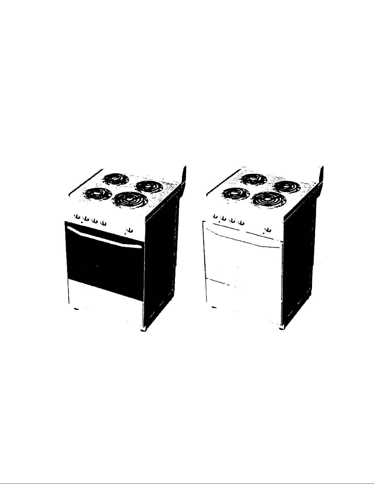
24” Electric Freestanding Range
Instruction Manuai
DER24 CW
ER24AW/ DER24CW / DER24CSS
ER24 AW
CAUTION:
BEFORE USE, PLEASE READ AND FOLLOW ALL SAFETY RULES AND
OPERATING INSTRUCTIONS. SAVE THESE INSTRUCTIONS FOR LATER USE.
Avanti has a policy of continuous improvement on its products and reserves the right to change materials and specifications without notice.
Avanti Products, A Division of The Mackle Co., Inc.
P.O. Box 520604 - Miami, Florida 33152
www.avantiproducts.com
IMU I I2<i/Rl>
Page 2

Cus tomer
Customer Product Code
Product Code
Description
Exploded Drawing No
Valid Thru
AVANTI
DER24 CW
TFB1SUSA02
:TFS18USA02
; 16 NOV 200 0
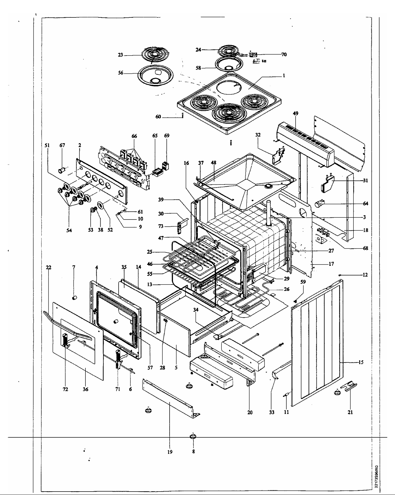
No
Code Description
1
01540E01
2
024 1 7502
3
0302 1 107 TEBIS F'JNNEL
A
03100E1 1
5
03786H31
6
O4024T01
7
05010104
3
05040102
9 05053002
10 05053003
11 05072507
12 05072521
ТГВ18 PLATE
TFB13USA02 AVANTI CONTROL PANEL
TFB OVEN DOOR
TFB VilDE TYPE DRAWER, WHITE
TFB/TFA LOWER STRIP FOR GLASS
TFG/TFB/TFA BUMPER FOR HANDLE
TFG\TFB\TFT LEVELING FOOT (BLACK)
TFG/B/R/A SIGNAL LAWP CONTACT
SIGNAL LAMP CONTACT{SIGNALLUX)
BUMPER FOR drawer (BLACK)
TFG/BIS BUMPER FOR PLATE
13 05096108 TFB OVEN DOOR SEALING
14
05096113
И
07048T01
16
07049TQ1
17
08 122P
18
08123P
19 09767T01
20
09821T01
21 10016H01
22
10026T01
23 10110530
24 10110531
25 10110532
26 10110533
27
11536EU
29
12070C
29
12278P
12279P
30
31 12350T01
32 12351T01
33 12755H07
34 12756H08
35 13010251
36 13010835
37 14030202
38 14520105
14560103
39
40 15050233
41 15050350
42 15050354
43
15050360
44
15050368
45 15050369
46
15051E11
47
15062E11
48
15093E11
49
15761S01
50 16011126
51
16041575
5 2
16041576
53 16C99H2 L
INNER GLASS SEAL
TFU CABINET RIGHT SIDE PANEL H.O HOB COVER
TFU CABINET LEFT SIDE PANEL W.O. HOB COVER
TFB18 BACK INNER COVER
TFB18 OUTER CABINET BACK COVER
TFB SUPPLEMENT BOTTOM PLINTH
TFB BASEMENT FRONT/ REAR ELEMENT PCS 2
ANTI TIP BRACKET
TFA/B ALUMINIUM HANDLE
DIA.180 BURNER 208/240V, 1580/2100W
DIA.145 BURNER 208/240V, 940/1250W
USA TYPE GRILL TUBE HEATER,240V 2300W
USA TYPE LOWER TUBE HEATER,240V 2000W
TFB18 INNER OVEN
TFA-TFB INNER GLASS ASSEMBLY ELEMENT PCS
TFA/B/G/U HINGE SUPPORT ELEMENT,RIGHT PCS
TFA/B/G/U HINGE SUPPORT ELEMENT,LEFT
TFG/B18 RIGHT CONSOLE PCS
TFG/B18 LEFT CONSOLE PCS I
TFB DRAWER GUIDE WITH CONSOLE,RIGHT
TFB DRAWER GUIDE WITH CONSOLE,LEFT
TFB/G/A_INNER GLASS LOW-E PCS
TFB INOX GLASS
TFG/B18 PLATE SUPPORTING BAR
TFG/B/A KNOB SPRING PCS
THERMOSTAT CLIP PCS
TFB BOTTOM STYRAPHOR PCS
TF8/G SPLASH GUARD FRONT STYRAPHOR
TF3/G LEFT FRONT STYRAPHOR
TFB PLATE STYRFOR PCS
TFB/TFG18 RIGHT BACK STYRAPHOR
TFB/TFG18 LEFT BACK STYRAPHOR
TFG/B OUTER TRAY
TFG/B/A INNER TRAY
TFB18 SPLASH TRAY
TFB18 AVANTI SPLASH PLINTH
TFB18 AVANTI INSTRUCTION MANUAL
TFG/B LOWER PART OF HOB KNOB,WHITE
TFB/G LOWER PART OF FUNCTION KNOB
TFA/B/G OVEN SWITCH KNOB WITH
SEGMENT(PROFILE Z TYPE,WHITE)
54 16099H22
55
56
57
58
59
17010147
13009?
13C10101
18010?
18020211 TFG/BIS PLATE HINGE
60 18020212
2 0 00 IH SIGNAL LAMP WIRING
61
62 23392S02
6 3
27002H34
60u50b0i
6 4
65
60060332
TFA/B/G HOB/TIMER SWITCH KNOB WITH SEGMENT TF3 INNER GRID
8" REFLECTOR BOWL
TFB-TFG WIRE RACK SYSTEM FIXING NUT
6" REFLECTOR BOWL
TFG/B18 PLATE LOCK PIN
TF318USA02 AVANTI BOX
TFBia USA CABLE GROUP
OVEN LAi'lt'
OVEN SWITCH 250V T150
66« 60054414 SWITCH 240V\13A\
67
60071401
TFG21 INNER ILLUMINATION BUTTON,PUSH ON-PUSH PCS
OFF
68 60093605
60120913
69
60140407
70
68020107
71
72 68020200
USA TYPE TERMINAL BOX PCS
THERMOSTAT
USA TYPE BURNER CONNECTOR CLIPS
RIGHT HINGE
LEFT HINGE
Unit
Quantity
PCS
PCS
PCS
PCS
PCS
PCS
PCS
PCS
PCS
PCS
PCS
PCS
PCS
PCS
PCS 1
PCS 1
PCS 1
PCS
PCS 1
PCS 1
PCS 1
PCS 1
PCS 3
PCS
PCS
PCS
PCS
PCS
PCS
PCS
PCS
PCS
PCS
PCS
PCS
PCS
PCS
PCS
]_
PCS
PCS
PCS
PCS
PCS i
PCS 4
PCS 1
PCS 1
PCS 2
PCS
PCS
PCS
PCS
PCS i
PCS
PCS
----PCS
PCS
PCS
PCS
PCS
PCS
■p
1
1
1
1
1
1
2
4
2
2
2
1
1
1
1
1
1
2
1
1
1
1
1
i
1
1
5
I
1
1
1
1
1
1
1
1
1
4
1
3
2
2
2
1
4
1
1
1
4
1
1
Page 3
Page 4

Warranty Information
Thank you for purchasing this fine Avanti product. Please fill out this card and return it within
100 days of purchase and receive these
important benefits;
Confirm your warranty:
Your prompt product registration confirms your right to the protection available under the
terms and conditions of your Avanti warranty.
Protect your product:
We will keep the model number and date of purchase of your new Avanti product on file
to help you refer to this information in the event of an insurance claim such as fire or
theft.
Promote better products:
We value your input. Your responses will help us develop products designed to best
meet your future needs.
-(detach here)-
Avanti Registration Card
Name
Address
City
State Zip
Area Code Phone Number
Did You Purchase An Additional Warranty:
□Extended DFood Loss GNone
Reason For Choosing This Avanti Product:
Please indicate the most important factors
that influenced your decision to purchase
this product.
□ Price
□Product Features
□Avanti Reputation
□Product Quality
□Salesperson Recommendation
□Friend/Relative Recommendation
□Warranty
□Other
_____________________________________
Model #
Date Purchased
Occupation
As Your Primary Residence. Do You:
□Own GRent
Your Age:
□under 18 G18-25
□31-35 G36-50
Marital Status:
□Married GSingle
Is This Product Used In The:
□Home ' OBusiness
How Did You Learn About This Product:
□Advertising
□ In Store Demo
□Other__
Comments
Serial #
Store/Dealer Name
□26-30
□over 50
□Product Features
□Personal Demo
_____
16020062/R0
Page 5

TABLE OF CONTENTS
{MPORTANT SAFETY iNSTRUCTiONS........................................................................................3
GETTING TO KNOW YOUR RANGE.............................................................................................6
INSTALLATION INSTRUCTIONS...................................................................................................7
Cabinet Dimensions.....................................................................................................................7
Product Dimensions.....................................................................................................................8
Electrical Requirements...............................................................................................................8
Electrical Connection................................................................................................................. 9
Levelling of Range.....................................................................................................................10
Anti-Tip Bracket Installation....................................................................................................... 10
OPERATING YOUR RANGE....................................................................................................... 11
Using the Surface Units.............................................................................................................11
Cookware tips.............................................................................................................................12
Using the Oven..........................................................................................................................12
Bake......................................................................................................................... :
Broil............................................................................................................................................13
Oven Rack
Oven Light (available on some models).....................................................................................13
CARE AND CLEANING OF YOUR RANGE
Surface Units and Reflector Bowls.............................................................................................14
Lift-up Cooktop...........................................................................................................................14
Lift-off Oven Door.......................................................................................................................15
Lift-off the Drawer (available on some models)
Control Panel and Knobs...........................................................................................................15
Oven Vent.................................................................................................................................. 15
Metal Parts
Painted Surfaces........................................................................................................................16
Enamelled Cooktop, Cavity, Broiler Tray...................................................................................16
Glass Window (available on some models)...............................................................................16
TROUBLESHOOTING................................................................................................................. 17
WARRANTY..................................................................................................................................18
.................................................................................................................................13
.................................................................................
.........................................................................
................................................................................................................................16
.................
12
14
15
IWil 1
Page 6
IMPORTANT SAFETY INSTRUCTIONS
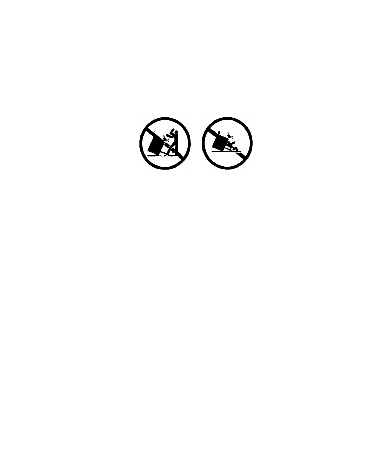
WARNING:
ALL RANGES CAN TIP AND INJURY COULD RESULT. TO PREVENT ACCIDENTAL TIPPING
OF THE RANGE ATTACH IT TO FLOOR BY INSTALLING ANTLTIP BRACKET SUPPLIED. If the
range is moved, reconnect anti-tip bracket. To check if the anti-tip bracket is installed properly,
remove the storage drawer and inspect the rear levelling legs. Make sure it fits securely into the
slot.
CAUTION:
DO NOT STORE ITEMS OF INTEREST TO CHILDREN IN CABINETS ABOVE A RANGE OR ON
THE BACKGUARD OF THE RANGE - children climbing on the range to reach items could be
seriously injured.
CAUTION:
DO NOT TOUCH SURFACE UNITS, HEATING ELEMENTS, INTERIOR SURFACES OF OVEN
OR AREAS NEAR UNITS - Surface units and heating elements may be hot even though they are
dark in color. Areas near surface and interior surfaces of oven may become hot enough to cause
burns. During and after use, do not touch,or let clothing or other flammable materials contact
surface units or areas near units untill they have had sufficient time to coll. Other surfaces of the
appliance may become hot enough to cause burns - for example oven door and window of oven
door.
Genera!
Electric ranges have been thoroughly tested for safe and efficient operation. However, as with any
appliance, there are specific installation and safety precautions that must be followed to ensure
safe and satisfactory operation.
• Read all instructions before using the range.
• Use this appliance only for its intended use as described in this manual.
• Be sure your appliance is properly installed and grounded by a qualified technician in
accordance with the Installation Instructions.
• Do not repair or replace any part of the appliance unless specifically recommended in the
manual. All other servicing should be referred to a qualified technician.
• After prolonged use of your range, high floor temperatures may result. Many floor coverings
will not withstand this kind of use. Before installing your range on linoleum or any other
synthetic floor covering, make sure the floor covering can withstand 100°C without shrinking,
warping or discoloring.
Continued on next page
iNH i
Page 7

Do not install the range over carpeting unless a sheet of ’л" thick plywood or similar insulator is
■placed between the range and carpeting.
Do not leave children alone or unattended where a range is hot or in operation.
Never use your appliance for heating the room. Your oven and cooktop are not designed to
heat your kitchen. The surface unit should not be operated without cookware.
Do not let cooking grease accumulate in or near the range.
Never pick up a flaming pan. Turn the controls off.
Do not use water on grease fires. Flaming-grease outside a pan can be put out by covering it
with baking soda, multipurpose dry chemical, or fire extinguisher. Flame in the oven can be
smothered completely by closing the oven door and turning the oven off or by using baking
soda, multipurpose dry chemical, or fire extinguisher.
Do not store or use combustible materials in an oven, storage drawer, or near the cooktop.
Never wear loose fitting or hanging garments while using the appliance. Be careful when
reaching for items stored in cabinets over the cooktop. Flammable material could be ignited if
brought in contact with the surface units or hot oven surfaces and may cause severe burns.
Use only dry pot hoiders-moist or damp potholders on hot surfaces.may result in burns from
steam. Do not let potholder touch hot heating elements. Do not use a towel or other bulky
cloth.
Always turn the surface units to OFF before removing cookware.
Never leave surface units unattended at high heat settings. Boilover causes smoking and
greasy spillovers that may ignite.
Use proper pan size. This appliance is equipped with surface units of different size. Select
utensils having fiat bottoms large enough to cover the surface unit heating element. The use of
undersized utensils will expose a portion of the heating element to direct contact and may
result in ignition of clothing. Proper relationship of utensii to heating element will also improve
efficiency.
Make sure reflector pans are in place. Absence of these pans during cooking may subject
wiring or components underneath to damage.
Do not use aluminium foil to line surface unit reflector pans. Installation of these liners may
result in a risk of electric shock, or fire.
Do not soak removable heating elements. They should never be immersed in water.
Utensii handles should be turned inward and not extend over adjacent surface units. To reduce
the risk of burns, ignition of flammable materials, and spillage due to unintentional contact with
utensil, the handle of a utensii should be positioned so that it is turned inward, and does not
extend over adjacent surface units.
Foods for frying should be as dry as possible. Frost on frozen foods or moisture on fresh foods
can cause hot fat to bubble up and over the sides of the pan. Use the least possible amount of
fat for effective shallow or deep fat frying. Overloading the pan with fat can cause spillovers
when food is added.
If oils or fats will be combined when frying, stir them together before heating as fats melt
slowly.
Always heat fat slowly and watch as it heats.
Use a deep-fat thermometer whenever possible to prevent overheating fat beyond the smoking
point.
Never try to move a pan of hot fat, especially a deep fat fryer. Wait until the fat is cool.
When using glass cookware, make sure it is designed for top-of-range cooking.
Do not leave any items on the cooktop. The hot air from the vent may ignite flammable items
_and will increase pressure in closed containers, which may cause them to burst.
Do not use the oven as a storage area. Items stored in the oven can igniie.
Continued on next page
iw)i n:wRi>
Page 8

Stand away from the range when opening the door of a hot oven. The hot air and steam that
escape can cause burns to hands, face, and eyes.
Keep the oven free from grease buildup.
Keep oven vent ducts unobstructed.
Place the oven shelves in the desired position while the oven is cool. If the rack must be
moved while oven is hot, do not let potholder contact hot heating element in oven.
Do not heat unopened food containers. Pressure could build up and the container could burst,
causing ah injury.
Do not use aluminium foil anywhere in the oven except as described in the manual. Misuse
could result in a fire hazard or damage to the range.
When using cooking or roasting bags in the oven, follow the manufacturer instructions.
Use only glass cookware that is recommended for use in electric ovens.
Never entirely cover a shelf with aluminium foil. This will disturb the heat circulation and result
in poor baking.
To eliminate the risk of burns or fire by reaching over heated surface units, cabinet storage
space located above the surface units should be avoided. If cabinet storage is to be provided,
the risk can be reduced by installing a range hood that projects horizontally a minimum of 5
inches beyond the bottom of cabinets.
- SAVE THESE INSTRUCTION
Page 9

GETTING TO KNOW YOUR RANGE
This section contains the illustration of your range in order to make you familiar with your electric
range.
Backguard
Cooktop
Oven Vent
S" Burner with
Reflector Bowl
Back Panel
Control Panel
Oven Ooor
Enamelled Sheet Metal
[Model ER24AW)
Side Panel
Over Ooor Hinge
Anti-tip Bracket
Removable Storage Drawer
Kick Panel (Model OER24CW)
Kick Panel (Model ER24AW)
Rating Plate
Levelling Leg
Page 10

INSTALLATION INSTRUCTIONS
Cabinet Dimensions
A qualified technician must install this range. Make sure you have everything necessary for correct
installation, it is the installer’s responsibility to comply with installation clearances specified on the
rating plate. It is located on the bottom frame below the storage drawer panel or front panel.
Cabinet opening dimensions that are shown below must be used. Given dimensions are minimum
clearances.
Ihtll!
Page 11

Product Dimensions
40" to 40.79"
overall height
Electricai Requirements
This appliance must be properly installed and grounded by a qualified technician in accordance
with the National Electrical Code ANSI/NFPA No. 70 (latest edition) and local electrical code
requirements.
This appliance may be connected by means of permanent “Hard Wiring” or “Power Supply
Cord Kit”.
Power supply cord is not supplied, but is available through your local electric supply house.
Use only 3-conductor or 4-conductor UL listed range cord rated at 40 amps with 125/250V
minimum voltage range. These cords may be provided with strain relief or conduit connector.
The range must be connected to the proper electricai voltage and frequency as specified on
the rating plate.
The range can be connected directly to the fused disconnect (or circuit breaker box^ through
flexible, armoured or non-metallic sheathed, copper cable (with grounding wire). Allow two to
three feet of slack in the line so that it can be moved if servicing is ever necessary.
8
iwii; ;>
Page 12

Eiecthca! Connection
3-Wire Power Cord instaliation
See Figure 1.
1-
Remove the back panel.
2-
Assemble the strain relief in
the hole on bracket.
Insert the power cord through
3-
the strain relief and tighten.
4-
Allow enough slack to easily
attach the cord terminals to the
terminal block.
5-
Remove the 3 wire terminal
nuts and washers from the
terminal block.
Plug the terminal holes of
6-
power cord. The neutral or
ground wire of the power cord
must be connected to the
neutral terminal located in the
center of terminal block. The
power leads must be connected to the outside terminals
Plug washers and tighten nuts securely.
7-
Assemble the back panel.
8-
4-Wire Power Cord Instatlation
See Figure 2.
1-
Remove the back panel.
Assemble the strain relief in
2-
the hole on bracket.
Insert the power cord through
3-
the strain relief and tighten.
Allow enough slack to easily
4-
attach the cord terminals to the
terminal block.
Remove the 3 wire terminal
5-
nuts and washers from the
terminal block.
6-
Remove the ground strap from
the frame of range and
terminal by removing its screw
and cutting it as shown in
figure 2.
Plug the terminal holes of power cord. The neutral wire of the power cord must be
7-
connected to the neutral terminal located in the center of terminal block. The ground wire of
the power cord must be attached to the frame of range buy using the green coloured
grounding screw. The power leads must be connected to the outside terminals.
8- Plug washers and tighten nuts securely.
9- Assemble the back panel.
Cut Ground Strap
Terminal Block
Neutral Wire
Power Wires
Bracket
Figure 2
Grounding Screw
Grounding Wire
Power Cord
Page 13

Levelling of Range
The range must be level to obtain proper operating. The
screw type leveling legs located on the corners at bottom of
range should be adjusted by turning them clockwise to make
the range higher or counter-clockwise to lowec the range until
the range is level (See Figure 3). Use a level on surface units
to check the levelling of the range.
Anti-Tip Bracket instaiiation
To reduce the risk of tipping the appliance by abnormal usage or improper door loading, the
appliance must be secured by properly installing the anti-tip device packed with the appliance.
1 - Place the anti-tip bracket on the
floor as shown in Figure 4. Antitip bracket can be installed on
either right or left side.
2- Mark the locations of 2 holes of
anti-tip bracket on the floor.
3- Use a 5/16" masonry drill bit and
insert plastic anchor.
4- Secure bracket to floor using
screws supplied.
5- Slide appliance into position
(See Figure 5).
NOTE; IF RANGE IS RELOCATED,
THE BRACKET MUST BE REMOVED
AND INSTALLED IN NEW LOCATION.
install the anti-tip bracket either left or right side.
‘The contour line of front pane! of appliance
10
Figure 4
IfxM 1
Page 14

OPERATING YOUR RANGE
This section describes how you will use the features of your new range. Before operating your
range, read this section thoroughly.
A slight odor and smoke are normal when a new cooktop and an oven are used for the first time. It
is caused by the heating of new parts and insulating materials and will disappear in a short time.
Therefore, we suggest you to operate each surface units, bake and then broil element without any
cooking purpose for 10 minutes.
Your range is equipped with two different sizes of surface units. Three of them are 6” and one of
them 8" in size. The surface controls are easily operated. Simply push in and turn in either
direction. When the element is energized, the indicator marked top {See in Figure 6) glows when
one or more of the elements is turned on.
The control switch has a variety of heat settings from low to high. The
range of heat is increased by turning the knob to "HI", decreased by
turning the knob to "LO".
The solid dot in the surface unit marker shows which surface unit is
turned on by that knob (See Figure 7).
The following table shows the recommended settings for usage of
surface element.
Settings
HI
5-HI
LO-4
LO
Recommended Usage
To start foods cooking
To bring liquids to a boil
To hold a rapid boilTo fry chicken or partakes
For gravy, pudding and icing
To cook large amounts of
vegetables
To keep food cooking after starting it
on a higher setting
To keep food warm until ready to
servR
______________
______________
------------------------------------
11
Page 15

Cookware tips
The physical characteristics of pots and pans influence the performance of any cooking systems.
Therefore, emphasis must be placed on the importance of using proper cookware.
V Use cooking vessels with flat bottoms and tight fitting lids to conserve energy and shorten
cooking times.
2- Only certain types of glass, glass/ceramic, ceramic, earthenware or other glazed utensils
are suitable for cooktop. Manufacturers suggest using low to medium heat selections when
using glass cookware.
3- Pan size should match the element size. A slightly larger pan covers the entire element and
prevents spillovers from contacting the heat surface and burning in. Using a smaller pan
than the element is a waste of energy.
4- To avoid spattering and to maximize efficiency,’ pan bottoms should be clean and dry
before coming in contact with the elements.
5- Wipe spills off the elements with a damp cloth as soon as they cool to cut down on clean
up time. Be sure the control is off.
If a surface unit stays red for a long time, the bottom of the pan is not flat enough or is too small for
the surface unit. Prolonged usage of incorrect utensils could result in damage to the surface unit,
cooktop, wiring and surrounding areas. To prevent damage use correct utensil, start cooking on HI
and turn control down to continue cooking.
Never leave an empty utensil, or one which has boiled dry, on a hot surface unit. The utensil could
overheat and damage the utensil or surface unit.
Always be sure that ail control knobs are turned to OFF and the indicator light is OFF when you
are not cooking.
Using the Oven
You can use your range for bake and broil. For that reason, the oven has two different heating
elements.
Bake
In bake function, only the lower hidden heating element is operated. You can turn it on
the knob located on the extreme right of control panel. The heating element for baking
by the thermostat. You can easily set different heating levels by
turning the knob clockwise. The thermostat adjusts the
temperature of cavity from warm (approximately 150 F) to 500
F depending on your setting (See Figure 8). During the
operating, oven indicator light is turned on and off. When
desired temperature is obtained, the light is off and when
desired temperature is not obtained, it will stay on.
In order to bake, use the following steps.
1 - Place the rack in the correct position, before turn the oven
on.
2- Turn the oven knob to the temperature you desire
3- Check food for doneness at minimum time on recipe. Cook
longer if necessary.
4- Turn the oven knob to OFF and then remove the food.
by using
is controlled
For. best cooking results, always remember that hot air must
circulate around the pans in the oven so that even heat reaches
12
IW11112WW
Page 16

al parts of the oven. Therefore, place the pans in the center of oven and allow at least 2” space
between pan and the surface of cavity.
Broil
For broiling, upper heating element is activated by turning the oven control knob clockwise to
BROIL position (See Figure 8). Although the broil function has only one temperature setting, the
thermostat maintains the heating level fixed. Therefore, oven indicator light is turned on and during
broiling. Follow these instructions for broiling:
1-
Piace the meat on broiler grid in broiler
pan. Always use the grid so that fat drips
into the broiler pan; otherwise the juices
may catch on fire.
2-
Position the rack on the desired shelf
position. Put broiler tray on the rack.
Close the oven door.
34-
Turn the oven control knob to BROIL.
When broiling is finished, turn the oven
5-
control knob to OFF.
Always remember that when the oven is hot, outside surfaces of the range get hot.
Oven Rack
The rack is designed with stop-locks so that when placed
correctly on the rack supports, they will stop before
coming completely out from the oven, and will not tilt
when removing food from or placing food on them.
When placing cookware on the rack, pull the rack out to
the bump on the rack support (See Figure 10). Place the
cookware on the rack, then slide the rack back into the
oven.
To remove the rack from the oven, pull it to towards you,
tilt the front end upward and pull it out.
Oven Light (available on some models)
During cooking, you can observe the food without opening the oven door with
the oven light help. This saves energy.
In order to activate the light, push the LAMP button located at the extreme left of
the control panel (See Figure 11). To turn the light off, push the lamp button
again.
13
1ЫЧ I IZfvRII
Page 17

CARE AND CLEANING of YOUR RANGE
Your range is designed for easy care. This will help to keep it looking and operating like new many
years.
Surface Units and Reflector Bowls
Removing:
1 - Make sure ail surface units are off and
cool before removing surface units and ^
reflector bowls.
2- Lift the edge of unit, opposite the
receptacle, just enough to clear the
reflector bowl.
3- Pull the surface unit straight away from
the receptacle.
4- Lift out the reflector bowl
Replacing:
1- Make sure all surface units are off and cool
before removing surface units and reflector
bowls. .
2- Line up openings in the reflector bowl with
the surface unit receptacle.
3- Hold the surface unit as level as possible
with the terminal just started into the
receptacle. Push the surface unit terminal
into the receptacle.
4- When terminal is pushed into the receptacle
as far as it will go. push down the edge of
the surface unit opposite the receptacle.
Note: Do not immerse burners in water.
Surface Unit
Receptacle
Reflector Bowl
Figure 12
Lift-up Cooktop
You can reach the beneath of
cooktop for cleaning purpose by lifting
up the cooktop. In order to do:
1-
Hold the cooktop from front left
and right corners of cooktop and
pull it up.
After lifting the cooktop high
2-
enough, locate the support rod
and put it into place as shown in
figure 13.
Leave the cooktop on the tip of
3-
support rod.
4-
Wipe with warm soapy water. Use a soapy steel-wool pad on heavily soiled areas.
To lower the cooktop, lift cooktop holding from the front edge. Replace the support rod to its
5-
previous place. Lower the cooktop in its place. During replacing the cooktop, be sure that the
front edge of cooktop covers the upper edge of control panel.
Note: Do not drop the cooktop. Personal injury or damage to the cooktop frame could result
14
iNti.
Page 18

Lift-Off Oven Door
The oven door, glass or
enamelled sheet can be easily
removed for oven cleaning.
To remove it:
1- Open the door fully.
2- There is a small ring on
each hinge (See Figure
15). Pull the ring over the
claw-like hook, which is
part of the hinge
mechanism. Do not forget
to do this on both hinges
before the next step.
3- Raise the door slightly and
pull it straight out and
away from the oven. The
door will come completely
off.
To replace it:
1-
Position the hinges in the hinge slots on
oven frame.
2-
Hold the door horizontal and place both
small forms on oven frame.
3-
Slip the rings off the claw-like hooks.
4-
Close the door and make sure that it sits in
place fully, if not, repeat all above steps.
Lift-off the Drawer (available on some
models)
For cleaning, you can remove the drawer by
pulling it out until the stop point and lifting it up
(See Figure 17). Never store any flammable
material in the drawer.
Control Panel and Knobs
Clean up any spills or spatters with a damp
cloth. Remove heavier soil with warm, soapy
water. Clean the control panel with a mild
liquid dish detergent and a soft cloth. Rub
control panel lightly.
Oven Vent
The oven is vented through an opening at the
rear of the cooktop (See Figure 14). Never
cover the opening with aluminium foil or any
other material. This would prevent the oven
vent from working properly.
15
i«Mi i;wR4
Page 19

Metai Parts
Do not use steel wool abrasives, ammonia or commercial oven cleaners. To safely clean surfaces;
wash rinse and then dry with a soft cloth.
Painted Surfaces
Painted surfaces include the sides, the control panel, drawer or front panel and backguard. Clean
these with soap and water or a vinegar and water solution.
Enamefied Cooktopj Cavity, Broiler Tray
To clean the cooktop, cavity and broiler tray, use detergent and warm water. Rinse and polish with
a dry cloth. Never clean the broil element.
Glass Window (available on some models)
To clean the oven door inside and outside glass, use a glass cleaner. Rinse and polish with a dry
cloth.
16
iwii
Page 20

TROUBLESHOOTING
Problem
Surface units will not maintain a
roiling boil or frying rate is not
fast enough
Foods cook slowly
Surface units do not operate
Control knobs will not turn
Oven light does not work
Oven does not work
Food does not broil properly
Food does not bake properly
Possible Cause
• You must use pans that are absolutely flat,
• Pan bottoms should closely match the diameter of the
surface unit selected.
• Improper cookware being used.
• You have blown a household fuse or tripped a circuit
breaker
• The surface units are not plugged in all the way.
• You have not set the control knobs correctly.
• If it is a surface unit control knob, you are not pushing in
before turning.
• If it is oven control knob, you are trying to turn the knob to
wrong direction.
• Light bulb is loose or defective
• Switch operating oven light is broken
• You have blown a household fuse or tripped a circuit
. breaker
• You have not set the control knobs correctly.
• The oven control knob not set at BROIL.
• Improper rack position being used.
• Cookware is not suited for broiling.
• Oven thermostat is defective.
• The oven control knob does not set properly.
• Rack position is incorrect.
• Incorrect cookware or cookware of improper size is being
used.
• Oven thermostat is defective.
17
iw)i I i;^RM
Page 21

WARRANTY
LENGTH OF WARRANTY
FULL ONE-YEAR WARRANTY FROM
DATE OF PURCHASE ON ALL PARTS
EXCEPT GLASS PARTS
WE WILL PAY FOR
REPLACEMENT PARTS AND REPAIR
LABOR TO CORRECT DEFECTS IN
MATERIALS OR WORKMANSHIP.
SERVICE MUST BE PROVIDED BY AN
AUTHORIZED SERVICE COMPANY.
FULL 30-DAY WARRANTY FROM DATE
OF PURCHASE ON GLASS PARTS AND
FINISH OF PORCELAIN ENAMEL,
PAINTED OR BRIGHT METAL FINISHED
PARTS
WE WILL NOT PAY FOR
REPLACEMENT PARTS AND REPAIR
LABOR TO CORRECT DEFECTS IN
MATERIAL OR WORKMANSHIP. SERVICE
MUST BE PROVIDED BY AN AUTHORIZED'
SERVICE COMPANY.
A. Service calls to:
1. Correct the installation of your range.
2. Instruct you how to use your range.
• 3. Replace house fuses or correct house wiring.
4. Replace owner-accessible light bulbs.
B. Pickup and delivery. Your range is designed to be repaired in the home.
C. Damage to your range caused by accident, misuse, fire, flood, acts of God, or use of products not
mentioned in this manual.
D. Repairs to parts or systems caused as a result of unauthorized modifications made to the
appliance.
E. Repairs when your range is used in other than normal, single-family household use.
AVANTI PRODUCTS SHALL NOT BE LIABLE FOR INCIDENTAL OR CONSEQUENTIAL
DAMAGES.
Some states do not allow the exclusion or limitation of incidental or consequential damages, so
this exclusion or limitation may not apply to you. This warranty gives you specific legal rights, and
you may also have other rights that vary from state to state.
This warranty is not valid outside the continental United States.
Printed in TURKEY
18
iNii ii;wRi>
 Loading...