


VT-737SP
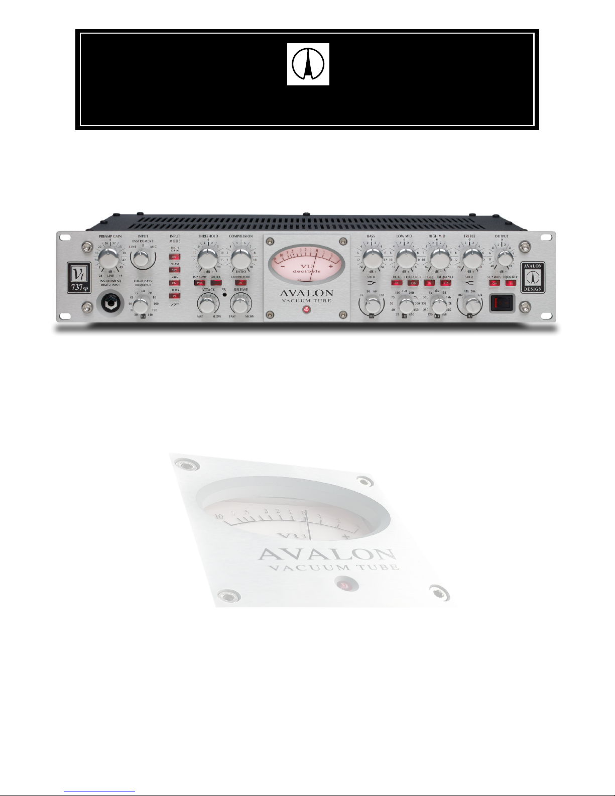
VT-737SP
Pure Class A Mono Vacuum Tube / Discrete
Preamplifier, Opto-compressor & Equalizer
Operation Manual
© 2016 Avalon Industries Incorporated. Release 2.0
D ESIGNAVA LON
P
URE
C
LASS
A M
USIC
R
ECORDING
S
YSTEMS

VT-737SP
Avalon Industries, Inc., 3715 Cahuenga Blvd, Studio City, CA 91604
Tel: 949-492-2000 www.avalondesign.com
Operation Manual


Table of Contents
1.0 Introduction . . . . . . . . . . . . . . . . . . . . . .5
1.1 Overview . . . . . . . . . . . . . . . . . . . . .6
1.2 Features . . . . . . . . . . . . . . . . . . . . . .7
1.3 Unpacking and Inspection . . . . . . . . .8
2.0 Quick Start-up . . . . . . . . . . . . . . . . . . . . .9
2.1 Setup Guide . . . . . . . . . . . . . . . . .10
2.2 Tips . . . . . . . . . . . . . . . . . . . . . .11
3.0 Safety and Grounding . . . . . . . . . . . . .12
3.1 Safety Instructions . . . . . . . . . . . .12
3.2 Grounding Instructions . . . . . . . . .12
3.3 AC Voltage Selection . . . . . . . . . .13
3.4 Rack Mounting and Cooling . . . . .14
3.5 Turn-on Procedure . . . . . . . . . . . .14
4.0 Operation and Controls . . . . . . . . . . . .15
4.1 Rear Panel Description . . . . . . . .18
4.2 Connections . . . . . . . . . . . . . . . .18
4.3 Unbalanced Operation . . . . . . . .19
4.4 Using the Vt-737sp . . . . . . . . . .19
4.4.1 Using the Mic Preamplifier. . . . .19
4.4.2 Using the Opto-compressor . . . .20
4.4.3 Linking Two Vt-737sp’s . . . . . . .21
4.4.4 Using the Equalizer . . . . . . . . . .21
4.4.5 Using the Side Chain . . . . . . . . .22
4.4.6 De-essing Vocals . . . . . . . . . . . .22
5.0 Applications . . . . . . . . . . . . . . . . . . . .23
5.1 Typical Setups . . . . . . . . . . . . . . .23
5.1.1 Recording . . . . . . . . . . . . . . . . .23
5.1.2 Mixdown - Tape Based . . . . . . .24
5.1.3 Mixdown - DAW . . . . . . . . . . . . .24
5.1.4 Mixdown / Mastering - DAW . . . .24
5.1.5 Mastering - Tape Based . . . . . . .24
5.2 Application Settings . . . . . . . . . . . . .24
5.2.1 Vocals . . . . . . . . . . . . . . . . . . . . . .25
5.2.2 Vocals with De-ess . . . . . . . . . . . .26
5.2.3 Bass Guitar . . . . . . . . . . . . . . . . . .27
5.2.4 Acoustic Guitar . . . . . . . . . . . . . . .28
5.2.5 Electric Guitar . . . . . . . . . . . . . . . .29
5.2.6 Acoustic Piano . . . . . . . . . . . . . . .30
5.2.7 Snare Drum . . . . . . . . . . . . . . . . . .31
5.2.8 Kick Drum. . . . . . . . . . . . . . . . . . . .32
5.2.9 Drum Overheads/Cymbals . . . . . .33
6.0 Basics . . . . . . . . . . . . . . . . . . . . . . . . . . .34
6.1 Impendance . . . . . . . . . . . . . . . . . . .34
6.2 Balanced vs. Unbalanced . . . . . . . .34
6.3 Cables and Connectors . . . . . . . . . .35
6.4 Microphones . . . . . . . . . . . . . . . . . . .35
6.5 Preamplifiers. . . . . . . . . . . . . . . . . . .36
6.6 Compression . . . . . . . . . . . . . . . . . .37
6.7 Equalization . . . . . . . . . . . . . . . . . . .38
7.0 FAQs (Frequently Asked Questions) . . . . . .39
8.0 Trouble Shooting . . . . . . . . . . . . . . . . . . .42
9.0 Service and Contact Infomation . . . . . . .42
10.0 Technical Information . . . . . . . . . . . . . .45
10.1 Recall Sheets . . . . . . . . . . . . . . . .46
10.2 Block Diagram . . . . . . . . . . . . . . . .47
10.3 Vt-737 (purple) vs. Vt-737sp . . . . .48
11.0 Warranty . . . . . . . . . . . . . . . . . . . . . . . . .48
11.1 Returns . . . . . . . . . . . . . . . . . . . . .49
12.0 Safety Standards . . . . . . . . . . . . . . . . . .49
Appendix A - Glossary . . . . . . . . . . . . . . . . . .50

Page 5Avalon Vt-737sp Operation Manual
1.0 Introduction
Welcome to Avalon and the world of Pure Class
A music recording systems. The Vt-737sp is an
extremely powerful, versatile and musical
direct recording path for combining the essetial
elements needed for professional music
recording: Class A vacuum tube preamplifier,
vacuum tube opto-compressor and discrete
parametric equalizer.
The Vt-737sp provides the recording professional with a versatile high-quality recording
channel, capable of amplifying, controlling, and
shaping a signal from its source and delivering
the signal directly to the audio recorder or DAW
(ditigal audio workstation) input, completely
bypassing the mixing console and its sonic
limitations.
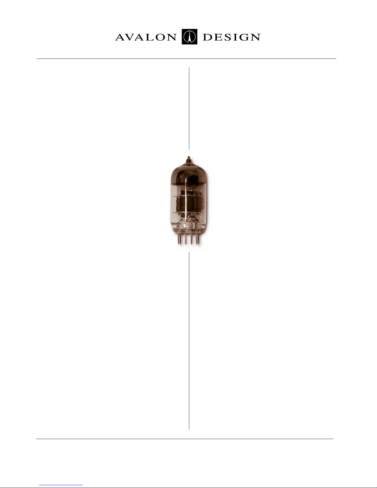
The Vt-737sp features a pure and minimal
signal path design utilizing advanced features
of high voltage, four dual triode vacuum tubes
and 100% discrete Class A circuit topologies.
The Vt-737sp combines a transformer-coupled,
dual vacuum tube preamplifier with a tube
opto-compressor and a high-voltage, discrete
Class A four-band parametric equalizer.
Twenty-two sealed silver relays provide
hard-wire bypass and multiple routing options
for total creative control and minimum signal
degradation. The output line driver combines
a dual triode vacuum tube with a low noise,
discrete high-voltage to current converter and
a balanced DC coupled output amplifier.
These elements along with many others in
the Vt-737sp provide pure balanced and
musical sound, extreme low-end definition
and amazing headroom.
The Vt-737sp is hand built in the U.S.A using
only the finest active and passive electronic
components available. Many of these parts
have been custom-manufactured exclusively
for Avalon.
A “no compromise” approach in every stage
of design and production ensures that the
Vt-737sp will give many years of dependable
high-quality service.
Introduction
Page 6 Avalon Vt-737sp Operation Manual
Introduction
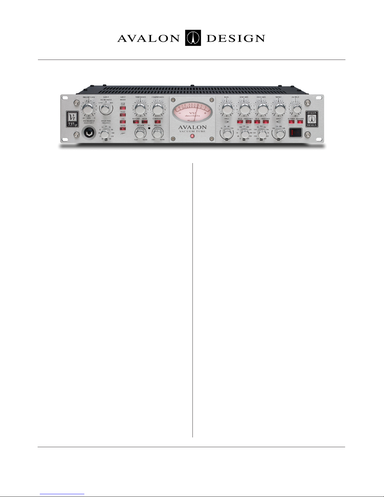
1.1 Overview
The Vt-737sp combines three essential fuctions
needed for professional recording: preamplifier,
compressor and equalizer. The Vt-737sp is
designed to completely bypass the mixing
board during input to deliver the purest and
cleanest signal possible to your recording
device. It works wonderfully for recording
directly into a digital device giving the signal a
richer and fuller sound. Each function of the
Vt-737sp can be used separately either as
a preamp, a compressor, or an equalizer,
or all functions can be combined in many
different ways for ultimate creativity and
unique new sounds.
The Vt-737sp preamplifier is a high
voltage vacuum tube design that can be
used for all types of microphones, direct
instruments such as guitars and basses,
and for line level devices such as keyboards,
mixing boards, recorders or DAWs. Three
different devices can be plugged into the
Vt-737sp simultaneously and can be easily
selected with the input mode switch on the
front panel. The microphone input has continuously variable gain from 0dB to +58dB including selectable 48 volt phantom power. A high
impendance (one megohm) input directly into
the vacuum tube circuit through an unbalanced
1/4” jack located on the front panel is used for
directly recording electric guitars or basses.
The compressor of the Vt-737sp utilizes twin
triode class-A vacuum tube circuitry with an
optical attenuator used as the gain reduction
element. The continuously variable threshold
level, compression ratio, attack, and release
controls can be easily adjusted to achieve a
variety of useful dynamic effects, from soft
compression to hard-knee limiting.
The choice of gain reduction level or input level
can be monitored on the VU meter. The compressor can be positioned either before or after
(pre or post) the equalizer giving even further
sonic flexibility. (Normal is pre EQ)
An added feature of the Vt-737sp is its
side-chain fuction for frequency selective compression capabilities. When the side-chain
switch is engaged, the two mid-band filters of
the equalizer section are inserted into the
compressor’s control circuit path, allowing
for frequency-sensitive dynamics control.
The wide frequency-range filters allow for
a variety of compression actions including
de-essing (sibilance control), or limited fr equency- range tightening and spectral
control.
A 1/4” unbalanced Stereo Link jack is also
provided on the rear of the unit to link two
Vt-737sp’s together for stereo operation.
The Vt-737sp equalizer is a 100% discrete high
voltage class A four-band parametric equalizer,
using both variable-active and switched-passive filter topologies. The TREBLE control is a
smooth, passive shelving type filter selectively
switched at 10kHz, 15kHz, 20kHz, and 32kHz
with +/-20dB of amplitude control. The BASS
control is also a passive shelf filter with selectable bands centered at 15Hz, 30Hz, 60Hz, and
150Hz. It also has +/-24dB of amplitude control. The Low Mid bandis an active peak/dip
filter, continuously variable from 30Hz to
450Hz. The x10 switch shifts the frequency
range from 300Hz to 4.5kHz, overlapping the
bands to give a possible range of 30Hz to
4.5kHz.
It has +/-16dB amplitude control and a
high/low Q (bandwidth) swtich which musically
sharpens the filter’s response from a Q of 0.2
(wide) to 0.85 (medium). The High Mid band
filter section is of the same type and covers a
frequency band of 200Hz to 2.8kHz. With the
X10 switch engaged, the filter covers the 2kHz
to 28kHz range. A high/low Q switch changes
the bandwidth in the same way as the Low Mid
band.
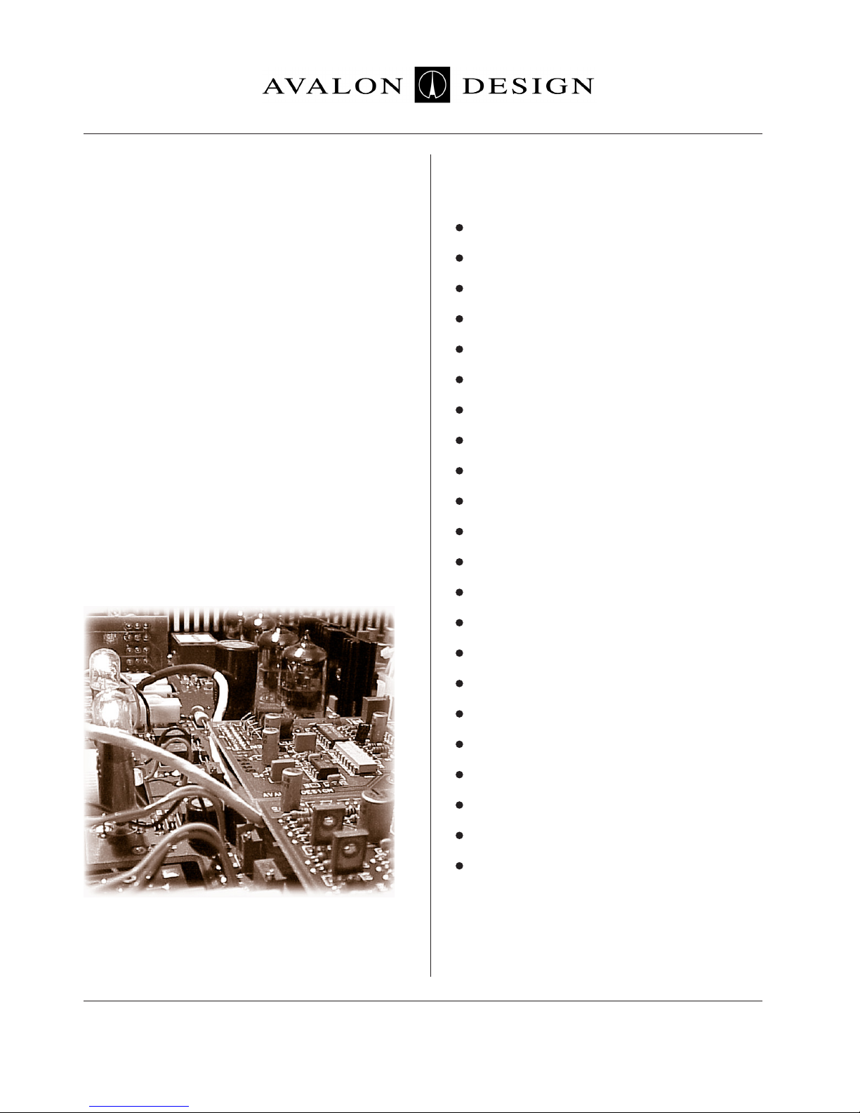
The output stage of the Vt-737sp is another
twin-triode vacuum tube stage driving a
balanced low-noise Class A DC-coupled
output amplifier. This stage includes an output
level control to give the final level adjustment
before leaving the unit via an XLR connector.
Inside view of Vt-737sp
1.2 Features
• Natural balanced musical performance
•
100% discrete pure Class A operation
•
Three simultaneously available inputs
•
Vacuum tube opto-compressor
•
Four-Band active-passive equalizer
•
Two-band EQ side-chain filter
•
Variable high-pass filter on all inputs
•
Twenty-two silver relays for signal routing
•
True hard-wired Bypass
•
Low noise, better than -90dB
•
High operating headroom +30dB
•
Fully balanced operation
•
Advanced microphone transformer
•
High-Z one megohm instrument input
•
Balanced line input +36dB
•
Tube-discrete balanced output amplifier
•
4 military grade dual triode vacuum tubes
•
High voltage signal path
•
2U nineteen inch welded steel chassis
•
Swtichable AC power supply 100-240V
•
150W toroidal shielded power transformer
•
Discrete soft-start DC power regulators
Avalon Vt-737sp Operation Manual Page 7
Introduction
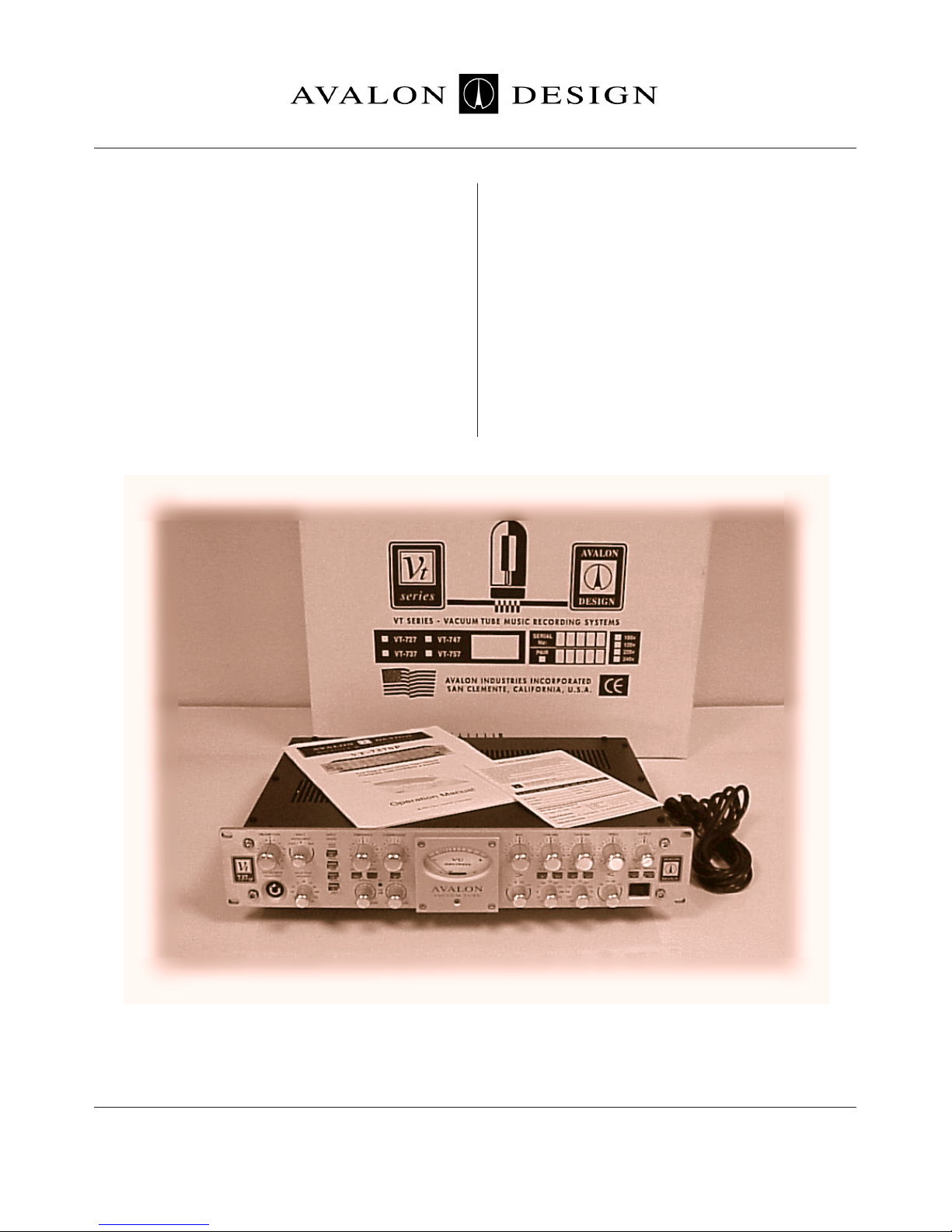
1.3 Unpacking and Inspection
Your Vt-737sp was packed carefully at the
factory. Check to make sure that the shipping
carton contains the following items:
1. Vt-737sp
2. Power cable
3. Warranty card
4. Operation Manual
Keep the packaging materials in case you need
to ship your unit for warranty service.
Note: Your must fill out and send in your warranty card in order to receive warranty and
technical support. If you have not already filled
out your warranty card please take the time to
do so now.
Vt-737sp contents and packing
Page 8 Avalon Vt-737sp Operation Manual
Introduction
Page 9
figure 2.0 Quick Start up
Avalon Vt-737sp Operation Manual
2.0 Quick Start-up
The following chapter is designed to help you
get started using your Vt-737sp right away
without having to read the entire manual. Make
sure however to take time to read the manual
at a later date as there are many safety aspects
and features of the Vt-737sp that will not be
discussed here.
If you are familiar with this type of equipment
you can also familiarize yourself with your
Vt-737sp and the functions with the Quick
Start-up Guide on page 10.
Note: The Vt-737sp is an extremely high
performance piece of musical equipment.
Every setting has great potential for creating
new and innovative musical sounds.
Do not be afraid of turning the knobs to
their full extreme positions!
Hook it up, turn it on and play:
1. Check on the rear of your unit that the power
supply is set for your local AC voltage. (120V in
U.S.) Refer to chapter 3.3 page 13 for details.
2. Plug in the AC power cable and connect
your microphone to the XLR input of the
Vt-737sp or an Instrument to the 1/4” jack on
the front panel. If your microphone needs
phantom power, push in the button labeled
+48V. Switch the input selector knob to indicate which input you are using (mic for the
microphone input, instrument for instrument
input, or line for line input). Connect the XLR
output to your recording device, powered
speaker or monitoring system.
3. Turn on the power and wait for one minute
while the soft-start procedure commences.
You may hear a relay click at about 45 seconds. During the soft-start procedure, the
Vt-737sp is in hard-wire bypass mode and will
pass signal, but the controls will not work.
For optimum performance, allow 30 minutes
for the Vt-737sp to fully warm up.
4. With all switches in the dis-engaged (non-illuminated) position, put signal through the
Vt-737sp with the input device you are using.
Adjust the output control on the right hand side
of the unit to check basic operation.
5. Now you are ready to start pressing switches and turning knobs! Let your ears guide your
sounds.
The Quick Set-Up Guide on the following page
gives a brief description of the switches and
controls on the Vt-737sp.
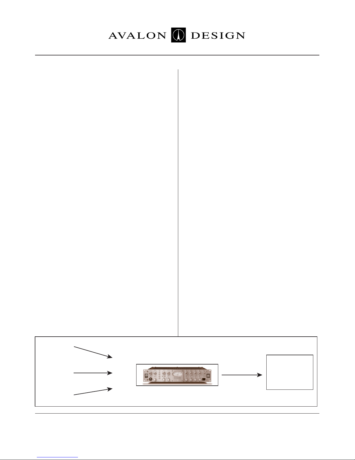
Mixing Console
or
Monitoring
System
Vt-737sp
Microphone
Instrument
Line Signal
-OR-
-OR-
Output
Input
Hi-Z
Instrument
Input
Mic Input
Line Input
Quick Start-up
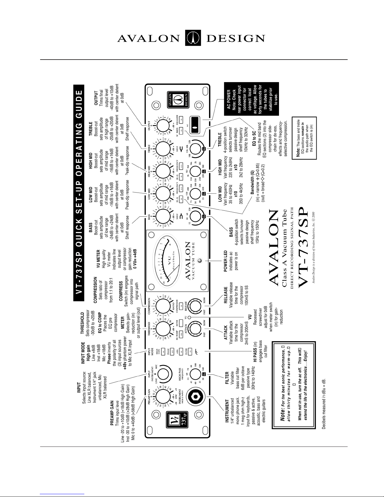
2.1 Set-up Guide
Page 10 Avalon Vt-737sp Operation Manual
Quick Start-up

Page 11Avalon Vt-737sp Operation Manual
2.2 Tips
UNITY LEVEL - The VT-737sp is calibrated so
that unity level is 0dB VU=+4dBu output.
PREAMP GAIN - Use the preamp gain control
as a gain control, not a level control. Turning up
the PREAMP GAIN will drive the tubes harder
for different tonality.
OUTPUT - Use the output control as the
overall level control.
EQ->COMP - Inserts the four band parametric
EQ before the compressor in the signal path.
SC-MID - Engages the built in side-chain. The
frequencies boosted in the Mids of the EQ will
be routed to the compressor control circuit (not
in the audio path) so that those frequencies are
compressed more than the overall program;
great for de-essing.
2.3 Tutorial - Using it all
The following is a tutorial that will quickly get
you familiar with all of the functions of the
Vt-737sp. Follow the steps below and in a few
minutes you will have used all of the functions
of the Vt-737sp.
Start by plugging a line level signal (CD player,
stereo keyboard, submix output, etc) into the
LINE INPUT in the rear of your Vt-737sp. If possible, run directly out of the Vt-737sp to monitors bypassing the console or mixing board.
Choose a musical selection, loop, patch,
sample or instrument with wide dynamic and
frequency range so you can experiment with
the compressor and equalizer.
Set all push button switches to their disengaged or non-illuminated position.
1. INPUT - Set to 0 center position. Adjust
OUTPUT control to set monitoring level.
2. HIGH GAIN - Press in and out to get a feel
for the sound of the high gain switch. Leave it
non-illuminated.
3. EQUALIZER - Press in equalizer switch and
familiarize yourself with the four band parametric band equalizer. Adjust the TREBLE Hz
frequency selector switch to 10K. Turn the
TREBLE knob up and down. You are now
boosting all frequencies at and above 10k.
Experiment with 15k, 20k, and 32k positions.
Leave the TREBLE level control at center 0
position. The BASS controls only the shelf is
in the opposite direction. So if you boost the
BASS at 60Hz you are boosting everything at
and below 60Hz.
Turn up the HIGH MID to +16. (Turn down the
OUTPUT if needed). Turn the corresponding
Hz knob directly below HIGH MID to 1k. This
means you are boosting the frequencies at
and around 1k by +16dB. Press in HI-Q. This
means your bandwidth around the 1k frenquencies is narrower or more focussed on 1k.
Now press in the X10 (read “times ten”)
switch. Now you are boosting the frequencies
at 10k (1k x 10 + 10k).
The LOW MID controls operate in the same
manner as the HI MID but cover a lower range
of frequencies.
Push the EQUALIZER swtich out (off) and
leave the EQ settings as they are (boosting
10kHz by +16dB).
Quick Start-up
3.0 Safety and Grounding
The following chapter describes how to safely
install your Vt-737sp for optimal sonic performance.
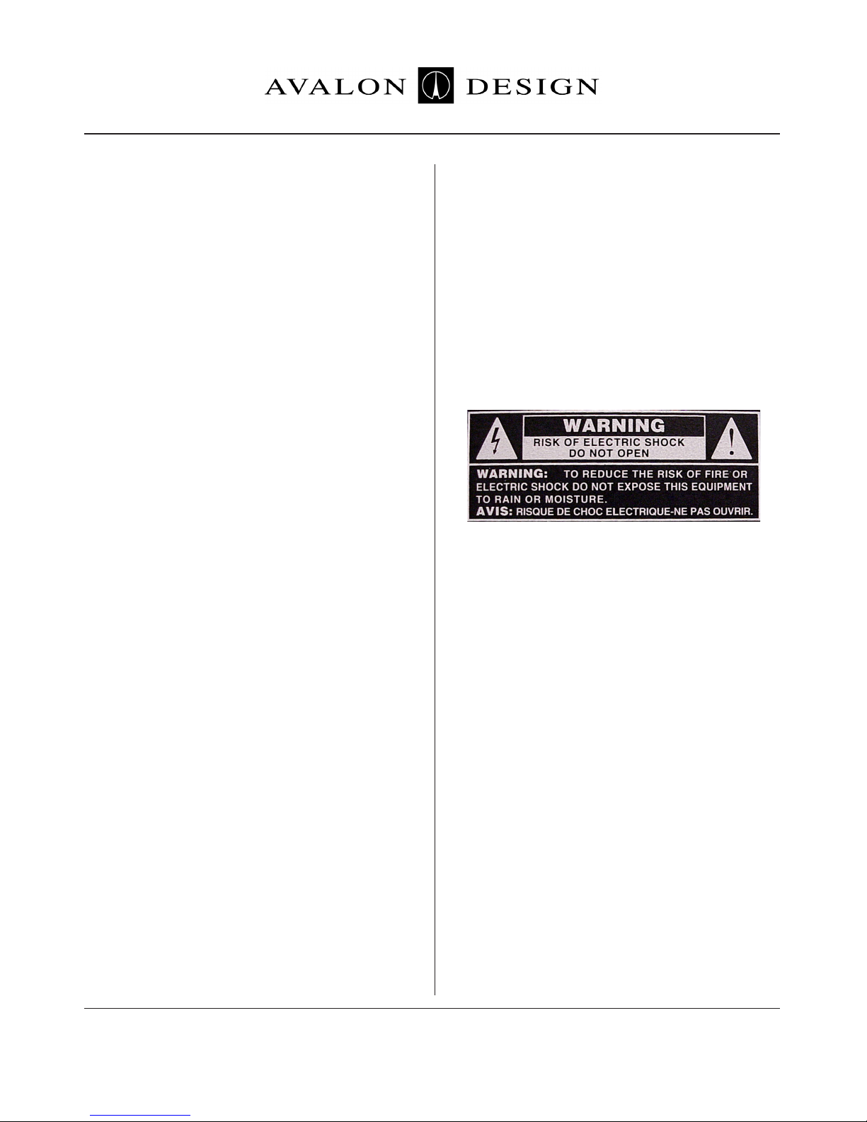
3.1 Safety Instructions
This unit contains voltages that can cause serious injury or death. Do not operate with the
covers removed.
Improper connection of the equipment-grounding cable can result in a risk of electric shock.
Check with a qualified electrician or serviceman
if you are in doubt about your electrical power
or ground connection. The Vt-737sp is for use
with an AC supply as selected by the AC voltage selector (located within the AC inlet on the
rear of the chassis). Voltages are
100-120-220-240VAC +/-0.5%, 50-60Hz at 75
watts.
3.2 Grounding Instructions
Always connect the Vt-737sp to a grounded
AC power circuit.
If the unit should malfunction or become “live”,
the chassis ground will provide the path of least
resistance for electric current to reduce the risk
of fatal shock.
4. COMPRESSOR - Press in the COMPRESSOR switch and turn the main compression
controls to the following:
COMPRESSION - full clockwise (20:1)
THRESHOLD - full counter clockwise (-30dB)
ATTACK - full counter clockwise (Fast)
RELEASE - full clockwise (Slow)
This is full compression with fast attack and
slow release. You can probably hear the compressor “pumping” or “breathing”. Play with
the compression controls to get a feel for the
compressor.
Leave the controls at full compression with fast
attack and fast release.
5. EQ->COMP - Press in EQUALIZER switch
(boosting 10kHz by +16dB). Press EQ->COMP
switch to insert the EQ before the compressor
in the signal path. This compresses the filtered
or “equalized” signal.
6. Press in SC->MIDS. You are now routing the
10K frequencies that were being boosted into
the compressor. This will compress the previsously boosted 10kHz frequencies more than
the other frequencies. Experiment now with the
HIGH MID level control to adjust the compression at 10kHz.
Now you have full compression, with fast
attack and slow release, and frequencies at
10K going into the side chain being compressed more than the overall signal.
You have now used all of the functions in the
Vt-737sp. The combinations, colors, and tones
are endless. For more details on each specific
control and fuction please refer to Chapter 4,
Operations and Controls (page 15).
Safety and
Grounding
Page 12 Avalon Vt-737sp Operation Manual
This product is equipped with an AC power
inlet and must be connected to a three-wire
grounded plug.
The AC power cable must be plugged into an
appropriate outlet that is correctly installed
and grounded in accordance with all local electrical safety codes and ordinances.
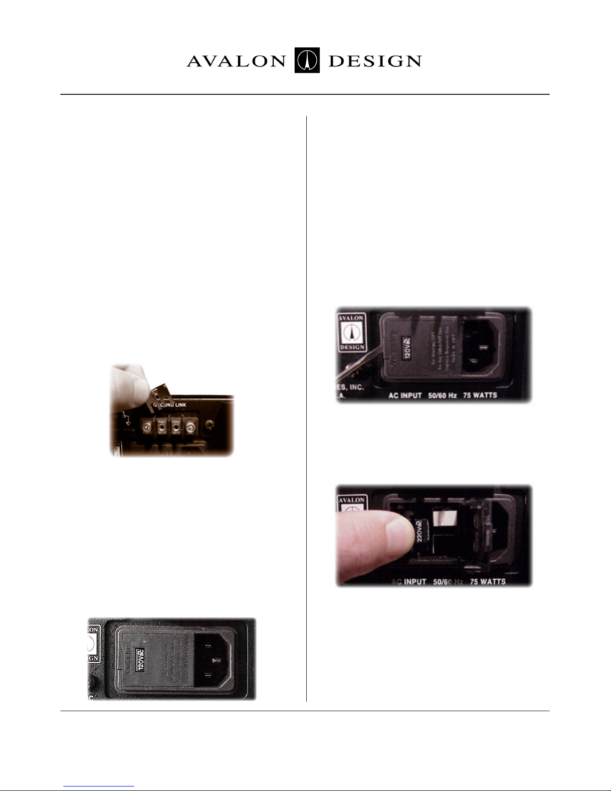
If hum or ground-buzz is induced into the
system, remove the rear-mounted
GROUND-LINK. This is ground-link isolates
the AC chassis ground from the audio ground.
When the LINK is removed, the AC ground
remains connected to the chassis via the AC
inlet connector and provides a direct path for
any electrical fault or dangerous condition.
Warning! No ground adaptor should ever be
used with this unit.
3.3 AC Voltage Selection
Before connecting the Vt-737sp to the AC
supply, check the OPERATING VOLTAGE
located on the rear of the chassis in the AC
inlet connector.
Voltages available are 100-120-220-240VAC
+/-0.5% 50-60Hz at 75 watts (USA used
120V).
To change the AC voltage for your location:
1. Make sure there is no AC power cable connected to the AC inlet.
2. Insert a small flat-head screwdriver tip into
the voltage selector cavity. Carefully lift-open
the hinged cover from left to right.
3. Rotate the selector wheel to show the
correct voltage for your location, then push the
wheel firmly into the mounting tabs.
4. Press the voltage selector cover snap-shut,
check correct AC voltage in window.
5. Connect the grounded AC power cable.
Safety and
Grounding
Page 13Avalon Vt-737sp Operation Manual

3.4 Rack Mounting and Cooling
The Vt-737sp is designed to be mounted in a
standard 19” equipment rack. As vacuum tubes
and Class A circuitry generate heat, it is highly
recommended that an additional rack space
above and below the unit be kept empty to
allow for adequate cooling. Avalon Design has
developed 1U ventilation panels (VP-1) specfically to keep your rack-mounted gear cool.
Be sure that the top and bottom of the unit is
not obstruced and air is allowed to flow easily
through the chassis. If the unit is not
rack-mounted, be sure to place supports under
the unit to allow air to pass underneath. Never
leave any obstruction on top of the unit (such as
papers or books) blocking ventilation slots.
Also, be sure that the heat sink mounted on the
rear panel of the chassis has adequate clearance from the equipment enclosure and any
adjacent equipment. In electronic equipment,
excessive heat is the cause of most component
failures. A little extra precaution to ensure
proper ventilation can help avoid equipment
Always use all four front panel-mounting
holes when mounting the Vt-737sp in a rack
enclosure. If not shipped in its original packing, the Vt-737sp should be transported in a
floating-type shock-mounted flight case.
Although the Vt-737sp is well shielded against
moderate electrical and magnetic feilds, care
should be taken to avoid areas that are in
proximity to large motor or power transformers. Locations near sources of high RFI (radio
frequency interference) such as computers or
digital effects devices should also be avoided.
Because of the microphonic nature of vacuum
tubes, areas of extreme vibration or sound
levels should also be avoided.
3.5 Turn-on Procedure
The Vt-737sp is designed with a “soft-start”
feature that slowly brings the unit to life when
the unit is powered on. This feature ensures
that there is no strain on the electronic components when it is activated. It takes approximately 45 seconds for the unit to go through
the “soft-start” turn-on procedure.
When the Vt-737sp is switched off or during
the “soft-start” turn-on procedure, it is in hard
wire bypass mode and the unit will pass signal
utlizing a hard wire relay but none of the controls will operate (line in to line out).
Allow the unit to warm up for at least thirty
minutes prior to use. This allows the components time to come up to temperature and
stabilize before recording begins.
It is recommended that the unit be turned
off during periods of “non-use” greater
than 4 hours.
Safety and
Grounding
Page 14
Avalon VP-1 vent panels
Avalon Vt-737sp Operation Manual
Operation and
Controls
Page 15Avalon Vt-737sp Operation Manual
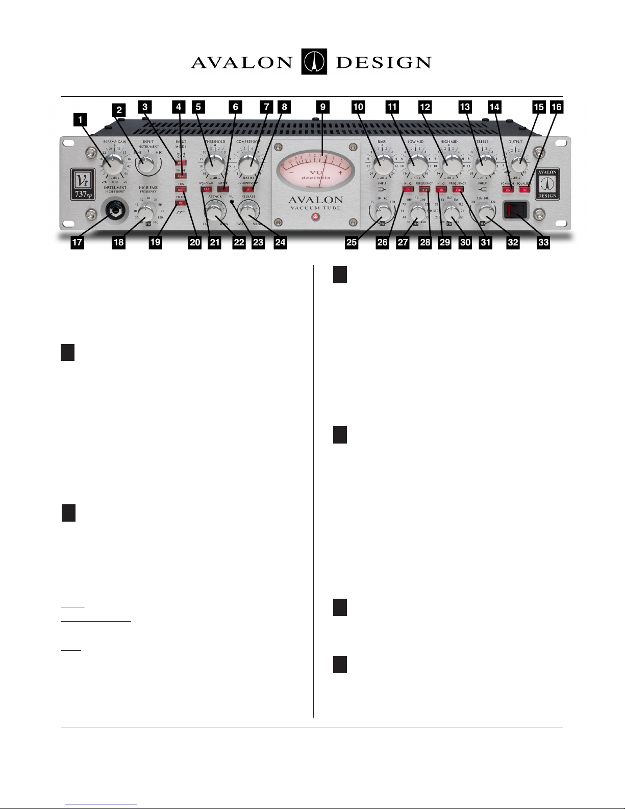
4.0 Operation and Controls
The following chapter describes the details of
your Vt-737sp and how to operate each function.
Continuously variable rotary control adjusts
input level of signal. This control will drve the
tubes harder to get more tube tone into the
preamp. The input has +36dB of headroom
before overload. You can use this control at minimum and maximum levels for different sounds
and colors. This control is a carefully configured
dual level control and does not change the feedback of the tubes.
3-position rotary switch that selects between
LINE, INSTRUMENT, or MIC input sources. This
switch corresponds to the following physical
input connections on the Vt-737sp:
LINE - XLR input on back labeled LINE
INSTRUMENT - 1/4” input jack on the front
panel labeled INTSRUMENT HIGH-Z INPUT
MIC - XLR input on back labeled MICROPHONE
All three input sources may be connected simultaneously but only the source that is selected
by the INPUT switch is active.
Boosts overall gain of the input/preamplifier
section by +8dB in Line mode and +18dB in Mic
or Instrument modes. The HIGH GAIN switch
fuctions with any selected INPUT position. This
extra signal boost can be effectively used in
conjunction with the OUTPUT control to overdrive the vacuum tube stages. Various effects,
from soft tube overdrive to all out distortion can
be achieved.
Reverses the output polarity. This feature
allows all three inputs the option of phase
reversal. Experiment with the phase switch to
defeat phase cancellation and create musical
effects.
The Vt-737sp always operates in “true phase”
from the input source to the output jack, whether bypassed or in-line (ie., a positive voltage on
input pin 2 yields a positive voltage on output
pin 2).
This control sets compressor threshold level.
Continuously variable from -30dB to +20dB.
When engaged the VU meter monitors the gain
reduction of the compressor. When disengaged, the VU meter monitors output level.
3 HIGH GAIN
4 PHASE
5 THRESHOLD
6 METER
2 INPUT
1 PREAMP GAIN

Operation and
Controls
Page 16 Avalon Vt-737sp Operation Manual
Sets the compression ratio. Continuously variable from 1:1 to 20:1.
When switch is engaged, the compressor is
inserted into the signal path. When disengaged, the compressor section is hard
bypassed by a sealed silver-contact relay.
Can be selected with the METER switch to
indicate either output level (non-illuminated) or
compressor gain reduction (illminated). The VU
meter’s needle is also speed sensitive for measuring gain reduction. This helps in setting the
ATTACK and RELEASE of the compressor
Sets amplitude (cut/boost)of bass band. Variable +/-16dB, with center detent.
Sets amplitude (cut/boost) of low mid band.
Variable +/-20dB with center detent.
Sets amplitude of high mid band. Variable
+/-16dB, center detent.
Sets amplitude (cut/boost) of shelving treble
frequency band. Variable +/-20dB with center
detent.
Inserts both of the mid band filter sections of
the equalizer into the compressors’ control
path, allowing for frequency-selective compression applications (e.g. de-essing vocals).
Adjusts the final output level. Variable -45dB to
+10dB, with center detent at 0 dBu.
Inserts equalizer into signal path. When disengaged, equalizer section is hard wire bypassed
by a sealed silver-contact relay.
1/4” unbalanced phone jack. High impendance
input selected when INPUT is in INSTRUMENT
position. Also known as D.I. (direct input. Instruments such as electric guitars and basses can
be directly plugged into this jack via a standard
shielded guitar cable.
Continuously variable rotary control that varies
the cut-off frequency of a passive high-pass
filter on the output of the preamp section. This
simple, smooth filter rolls off the low-end
frequencies and works well for reducing room
rumble, muddiness or microphone handling
noise.
Engages the preamp high pass frequency filter.
When the FILTER switch is not engaged, the
filter is hard wire bypassed.
48V phantom power is applied to microphone
input XLR. Both pins 2 and 3 carry 48V. Phantom power is necessary for most condenser
microphones that do not have their own external power supply.
A microphone that requires phantom power
will not work unless the +48V switch is
engaged.
8 COMPRESSOR
9 VU METER
10 BASS
11 LOW MID
12 HIGH MID
13 TREBLE
14 SC->MIDS
7 COMPRESSION (RATIO)
15 OUTPUT
16 EQUALIZER
17 INSTRUMENT (HIGH-Z INPUT)
18 HIGH PASS FREQUENCY
19 FILTER
20 +48v
Switches the signal so that the equalizer section is before the compressor. This gives flexibility to achieve different sounds. Putting the
EQ before the compressor will give the signal
a more squashed or tighter sound than if the
EQ follows the compressor.
Varies attack time of compressor from 2ms to
200ms.
Recessed screwdriver adjustment for setting
of 0dB on the VU meter when set to read the
compressor’s gain reduction.
To calibrate meter: Wait about 30 mintues
affter switching the unit on allowing components to sufficiently warm up to opertating
temperature. While there is no signal going
into the Vt-737sp, press in the METER switch
and make sure the compressor is bypassed
(non-illuminated). Adjust so that the needle on
the VU meter lines up with zero.
Engages the preamp high pass frequency
filter. When the FILTER switch is not engaged,
the filter is hard wire bypassed.
4-position switch selects shelving frequency
of the passive BASS band. Setting selections
are 15Hz, 20Hz, 60hz, and 150Hz.
When engaged, narrows the bandwidth of the
low-mid band frequency selected from an
approximate Q of 0.2 to 0.85.
Switches the signal so that the equalizer section is before the compressor. This gives flexibility to achieve different sounds. Putting the
EQ before the compressor will give the signal
a more squashed or tighter sound than if the
EQ follows the compressor.
Push-button switch when engaged (illuminated “X10”), multiplies the normally covered Hz
frequency band )30Hz to 450Hz) by ten (300Hz
to 4k5Hz).
Push button switch when engaged (illuminated
“IN”), narrows the bandwidth of the Hz
high-mid band selected, from a Q of approximately 0.2 to 0.85.
Sets center frequency of high mid filter section. Continuously variable from 200Hz to
2k8Hz (or 2kHz to 28KHz in X10 mode).
When engaged (illuminated X10), multiplies
the normally covered frequency band (200Hz
to 2k8Hz) by ten (2kHz to 28kHz).
4-position switch selects shelving frequency
of the passive TREBLE band. Setting selections are 10kHz, 15kHz, 20kHz, and 32kHz.
Turns the power on and off. Allow approximately 60 seconds from the time you turn on
the power switch for the Vt-737sp to complete
the entire soft start turn on procedure. For
more details on the soft start procedure please
refer to Chapter 3.5 Turn-on Procedure (page
21 EQ->COMP
27 Hz (LOW MID)
28 FREQUENCY X10 (LOW MID)
29 FREQUENCY X10 (LOW MID)
30 Hz (HIGH MID)
31 FREQUENCY X10 (HIGH MID)
32 HZ (TREBLE)
33 AC Power Switch
22 ATTACK
23 VU METER (0dB calibration screw)
24 RELEASE
25 Hz (BASS)
26 HI-Q (LOW MID)
Operation and
Controls
Page 17Avalon Vt-737sp Operation Manual
 Loading...