


Vashon Avanti DVS FS
Vashon
(Avanti DVS FS)
¥ Freestanding Direct Vent
¥ Residential or Mobile Home
¥ Natural Gas or Propane
- - Contact local building or
fire officials about
restrictions and
installation inspection
requirements in your area.
- - Save these instructions
WARNING: If the information in this manual is not followed exactly, a fire or explosion may result
causing property damage, personal injury or loss of life.
- Do not store or use gasoline or other flammable vapors and liquids in the vicinity of this or any other
appliance.
- WHAT TO DO IF YOU SMELL GAS
¥ Do not try to light any appliance.
¥ Do not touch any electrical switch; do not use any phone in your building.
¥ Immediately call gas supplier from a neighborÕs phone. Follow the gas supplierÕs instructions.
¥ If you cannot reach your gas supplier, call the fire department.
- Installation and service must be performed by a qualified installer, service agency or the gas supplier.
- April, 1999 -
Listed
10850 117th Place N.E. Kirkland, WA 98033
$10.00 93508102
ANSI Z21.44, ANSI Z21.11.1a-1993,
CAN/CGA 1-2.19-M81, CAN/CGA 2.17-M91,
U.L. 307b-1995, ANSI Z21.50-1996/CGA-2.22-M96
Tested to :
2 Safety Precautions
¥ IF YOU SMELL GAS:
* Do not light any appliance
* Extinguish any open flame
* Do not touch any electrical switch or plug or unplug anything
* Open windows and vacate building
* Call gas supplier from neighborÕs house, if not reached, call fire department
¥ This unit must be installed by a qualified installer to prevent the possibility of an
explosion. Your dealer will know the requirements in your area and can inform you of
those people considered qualified. The room heater should be inspected before use
and at least annually by a qualified service person. More frequent cleaning may be
required due to excessive lint from carpeting, bedding material, etc.
¥ The instructions in this manual must be strictly adhered to. Do not use makeshift
methods or compromise in the installation. Improper installation will void the warranty
and safety listing.
Ok
THIS CONTROL
HAS BEEN
CONVERTED FOR
NATURAL GAS
THIS CONTROL
HAS BEEN
CONVERTED TO
LP
¥ Contact your local building
officials to obtain a permit
and information on any
installation restrictions or
inspection requirements in
your area. Notify your
insurance company of this
heater as well.
¥ It is imperative that control
compartments, screens, or
circulating air passageways
of the heater be kept clean
and free of obstructions.
These areas provide the air
necessary for safe
operation.
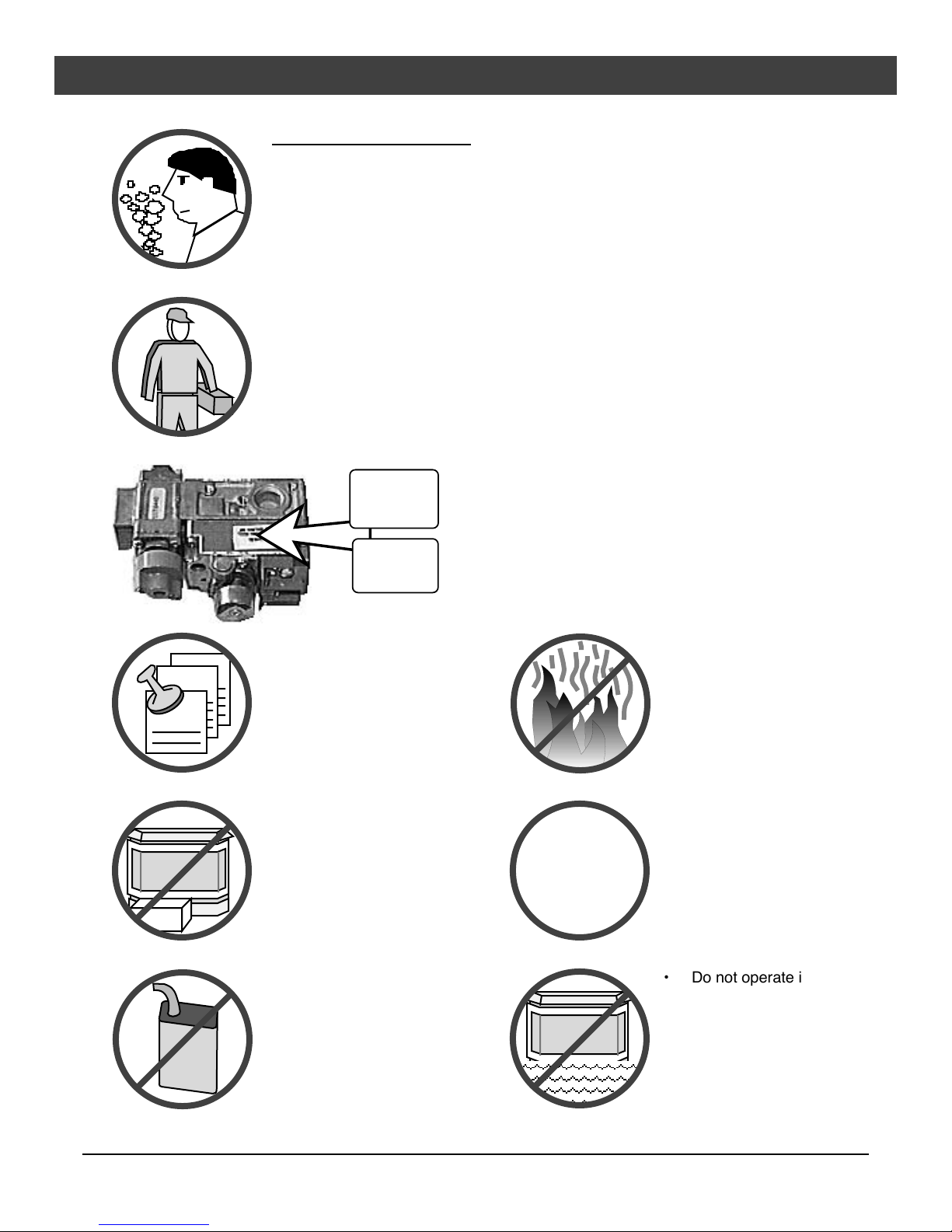
¥ This heater is either approved for natural gas (NG) or
propane (LP). Burning the incorrect fuel will void the
warranty and safety listing and may cause an extreme
safety hazard. Check the label above the gas control
valve to make sure it matches the fuel being used.
Direct questions about the type of fuel used to your
dealer.
¥ If the flame becomes sooty,
dark orange in color, or
extremely tall, do not
operate the heater. Call
your dealer and arrange for
proper servicing.
¥ Do not operate the heater if
it is not operating properly in
any fashion or if you are
uncertain. Call your dealer
for a full explanation of your
?
heater and what to expect.
¥ Do not store or use gasoline
or other flammable liquids in
the vicinity of this heater.
Gas
¥ Keep all furniture or other
combustible items at least
36Ó away from the front of
the heater.
Travis Industries 93508102 091002
¥ Do not operate if any portion
of the heater was
submerged in water or if any
corrosion occurs.

Safety Precautions 3
¥ Do not place clothing or
other flammable items on or
near the heater. Because
this heater can be controlled
by a thermostat there is a
possibility of the heater
turning on and igniting any
items placed on or near it.
¥ The door (glass) should only
be opened while lighting the
pilot or conducting service.
Damaged glass must be
replaced.
¥ Any safety screen or guard
removed for servicing must
be replaced prior to
operating the heater.
¥ Operate the heater
according to the instructions
included in this manual.
¥ If the main burners do not
start correctly turn the gas
off at the gas control valve
and call your dealer for
service.
¥ Light the heater using the
built-in piezo igniter. Do not
use matches or any other
external device to light your
heater.
¥ Never remove, replace,
modify or substitute any part
of the heater unless
instructions are given in this
manual. All other work must
be done by a trained
technician. DonÕt modify or
replace orifices.
¥ Allow the heater to cool
before carrying out any
maintenance or cleaning.
¥ The pilot flame must contact
the thermopile and
thermocouple (see the
illustration to the left). If it
does not, turn the gas
control valve to ÒOFFÓ and
call your dealer.
¥ This unit is not for use with
solid fuel
¥ Do not place anything inside
the firebox (except the
included fiber logs).
¥ If the fiber logs become
damaged, replace with
Travis Industries log set.
¥ Do not touch the hot
surfaces of the heater.
Educate all children of the
danger of a hightemperature heater. Young
children should be
supervised when they are in
the same room as the
heater.
¥ Instruct everyone in the
house how to shut gas off to
the appliance and at the gas
main shutoff valve. The gas
main shutoff valve is usually
next to the gas meter or
propane tank and requires a
wrench to shut off.
This
Manual
¥ Do not throw this manual
away. This manual has
important operating and
maintenance instructions
that you will need at a later
time. Always follow the
instructions in this manual.
¥ Plug the heater into a 120V
grounded electrical outlet.
Do not remove the
grounding plug.
¥ DonÕt route the electrical
cord in front of, over, or
under the heater
¥ Travis Industries, Inc.
grants no warranty,
implied or stated, for
the installation or
maintenance of your
heater, and assumes
no responsibility of any
consequential
damage(s).
Travis Industries 93508102 091002

4 Table of Contents
Introduction
Introduction......................................................1
Important Information .........................................1
Safety Precautions
Safety Precautions ............................................2
Specifications
Installation Options............................................5
Features ..........................................................5
Heating Specifications........................................5
Dimensions.......................................................5
Electrical Specifications (for optional blower)...........5
Fuel.................................................................5
Installation
Installation Warnings..........................................6
Packing List......................................................6
Installation Preparation.......................................6
Stove Clearances ..............................................6
Mobile Home Requirements..................................6
Heater Placement Requirements...........................7
Floor Protection Requirements..............................7
Gas Line Installation...........................................7
Gas Inlet Pressure ........................................7
Vent Requirements.............................................8
Approved Vent Configurations..............................9
Restrictor Position.........................................9
Elbows........................................................9
Measuring Vent Lengths.................................9
Vertical TermÕs with (or without) 2 45¡ Elbows ......10
Horizontal Terminations..................................11
Vertical TermÕs with Two 90¡ Elbows ..................12
Horizontal Vent Termination Requirements..............13
Vertical Vent Termination Requirements .................13
Finalizing the Installation.....................................14
Opening the Door...............................................16
Log Set and Coal Installation................................17
Operation
Safety Notice....................................................18
Location of Controls ...........................................18
Starting the Pilot Flame .......................................19
Starting the Heater for the First Time......................20
Turning the Heater On and Off ..............................20
Adjusting the Flame Height...................................20
Adjusting the Blower Speed..................................21
Normal Operating Sounds....................................21
Maintenance
Cleaning Your Heater..........................................22
Yearly Service Procedure....................................22
Troubleshooting Steps........................................23
How this Heater Works........................................24
Wiring Diagram ..................................................25
Safety Label
Safety Label .....................................................26
Warranty
Warranty..........................................................27
Optional Equipment & Addenda
LP Conversion Instructions..................................28
Blower .............................................................32
Thermostat.......................................................34
Remote Thermostat............................................35
Gold Door .........................................................35
Gold Grill..........................................................36
Firebrick...........................................................36
Index
Index...............................................................38
Travis Industries 93508102 091002

Specifications 5
Installation Options:
¥ Freestanding Stove
¥ Residential or Mobile Home
¥ Horizontal or Vertical Vent
Features:
¥ Works During Power Outages
¥ Realistic ÒWood FireÓ Look
¥ Optional Thermostat or Remote Control
¥ Variable-Rate Heat Output
¥ Optional Blower
Heating Specifications:
Approximate Heating Capacity (in square feet)*............500 - 1,500 with Blower, 500 to 1,200 Without
Input from Low to High (in BTUÕs per hour).................................................15,500 to 31,000
Steady State Efficiency............................................................................up to 80%
AFUE......................................................................................................70%
¥ Heating capacity will vary depending on the homeÕs floor plan, degree of insulation, and the outside
temperature.
** Efficiency rating is a product of thermal efficiency rating determined under continuous operation independent
of installed system. To measure the net BTUÕs, multiply the BTU input by the efficiency percentage.
Dimensions:
The starter
section is 1-1/2"
above the top.
4-3/4"
Measure
Clearances to
the Stove Top
28-5/8"
Weight: 165
Lbs.
22-1/8"
15-5/8"
Electrical Specifications (for optional blower)
Electrical Rating.........................................................115 Volts, 1.3 Amps, 60 Hz (150 watts on high)
Fuel:
This heater is shipped in natural gas (NG) configuration but may be converted to propane (LP) using
the included LP conversion kit. The sticker on top of the gas control valve will verify the correct fuel.
Travis Industries 93508102 091002
6 Installation (for qualified installers only)
S
C
Installation Warnings
! Failure to follow all of the requirements may result in property damage, bodily injury, or even death.
! This heater must be installed by a qualified installer who has gone through a training program for the
installation of direct vent gas appliances.
! This appliance must be installed in accordance with all local codes, if any; if not, follow current ANSI
Z223.1 or NFPA 54 in the USA or the current CGA B149 in Canada.
! In Manufactured or Mobile Homes this appliance must be installed to the applicable Mobile Home
Standards: CAN/CSA Z240 MH, the Manufactured Home Construction and Safety Standard, Title 24
CFR, Criteria for Manufactured Home Installations, Sites and Communities, and/or ANSI/NFPA 501A.
This appliance may be installed in Manufactured Housing only after the home is site located.
! This appliance is designed for natural gas or propane (LP). Check the sticker on top of the gas control
valve.
! All exhaust gases must be vented outside the structure of the living-area. Combustion air is drawn from
outside the living-area structure.
! Notify your insurance company before hooking up this appliance.
! The requirements below are divided into sections - all requirements must be met simultaneously.
Packing List
¥ Vashon (Avanti DVS FS) ¥ OwnerÕs Manual ¥ Log Set with Embers ¥ Propane Conversion Kit
Installation Preparation
HINT: If converting to LP, convert the appliance prior to installation.
HINT: Install the logs last - they are fragile.
HINT: When determining the location of the stove, locate the wall studs (for horizontal penetrations)
and ceiling trusses (for vertical penetrations). You may wish to adjust the stove position
slightly to ensure the vent does not intersect with a framing member.
HINT: Fumes and smoke from the paint curing and oil burning off the steel may occur the first time
you start this heater. This is normal. We recommend you open windows to vent the room.
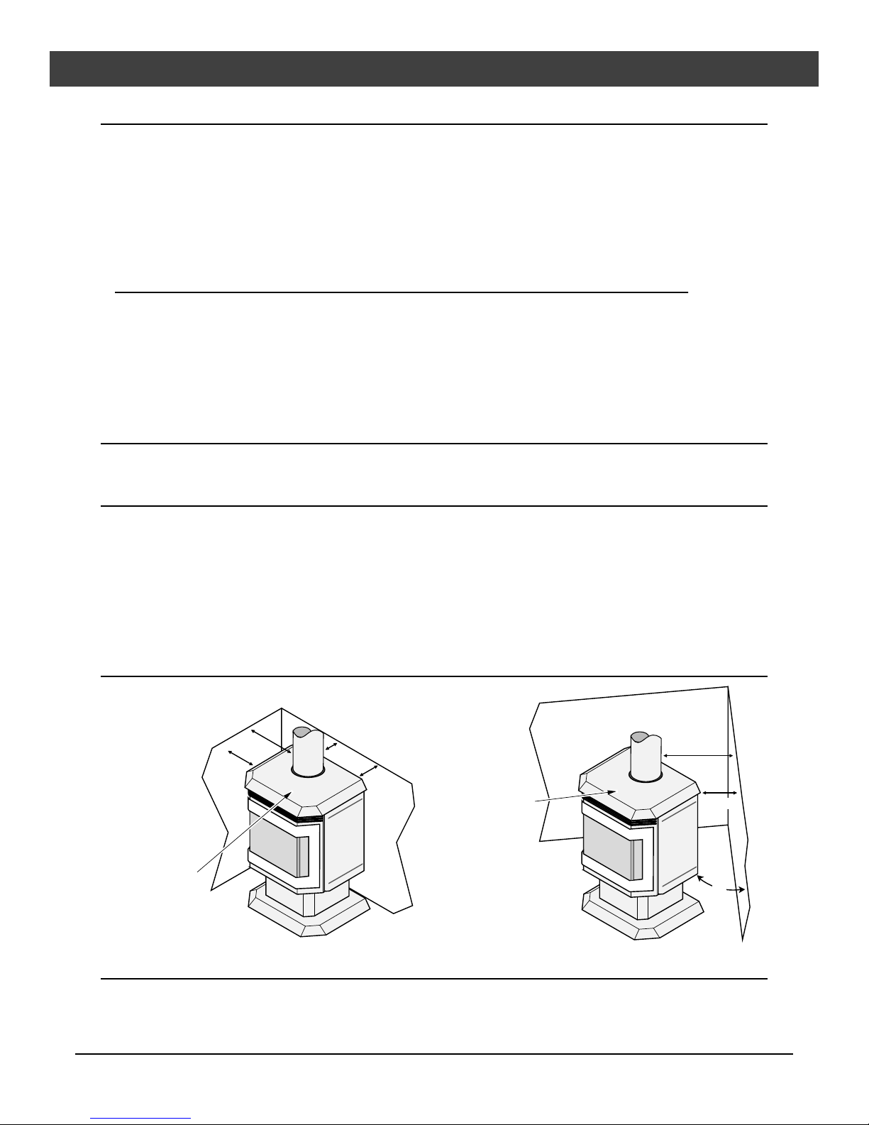
Stove Clearances
traight
Installations
10"
Min.
With this clearance
the vent is 6-3/8Ó from
the back wall, 17-7/8Ó
from the side wall.
Measure
Clearances to
the Stove Top
5" Min.
orner
Installations
Measure
Clearances to
the Stove Top
With this clearance, the vent
is 12-7/8Ó from the wall.
5" Min.
45¡
Mobile Home Requirements
¥ When the stove is installed in a mobile home, it must be bolted to the floor and the
appliance grounded (use the optional blower with a grounded circuit or other suitable
grounding method - current ANSI/NFPA 70 or CSA C22.1).
Travis Industries 93508102 091002
Installation (for qualified installers only) 7
Heater Placement Requirements
¥ Heater must be installed on a level surface capable of supporting the heater and vent
¥ Due to the high temperature of the heater, it should be located out of traffic and away from
furniture and draperies. Heater must be placed so no combustibles are within, or can
swing within 36Ó of the front of the heater (e.g. drapes, doors)
? When placed in a location where the floor to ceiling height is under 7 feet, the installation
is considered an alcove and must meet the following requirements:
¥ The alcove floor to ceiling height must be at least 58Ó tall
¥ The alcove must not be more than 45Ó deep before the ceiling returns to 7Õ
¥ The alcove must be at least 42Ó wide
¥ The heater must not be placed so the vents below or above the door, along the sides of
heater, or along the back of the heater can become blocked.
Floor Protection Requirements
¥ When the stove is installed directly on carpeting, vinyl or other combustible material other
than wood flooring or a high pressure laminate wood floor, the stove must be installed on
a metal or wood protection panel extending the full width and depth of the heater
(Minimum 22-1/8Ó wide by 15-5/8Ó deep).
Gas Line Installation
! The gas line must be installed in accordance with all local codes, if any; if not, follow
current ANSI Z223.1 or NFPA 54 in the USA and the current CGA B149 in Canada.
! The heater and gas control valve must be disconnected
from the gas supply piping during any pressure testing of
that system at test pressures in excess of 1/2 psig (3.45
kPA). For pressures under 1/2 psig (3.45 kPA), isolate
the gas supply piping by closing the manual shutoff
valve.
¥ This heater is designed for natural gas but can be
converted to propane. Check the sticker on the top of
the gas control valve to verify the correct fuel is used.
¥ Leak test all gas line joints and the gas control valve prior
to and after starting the heater.
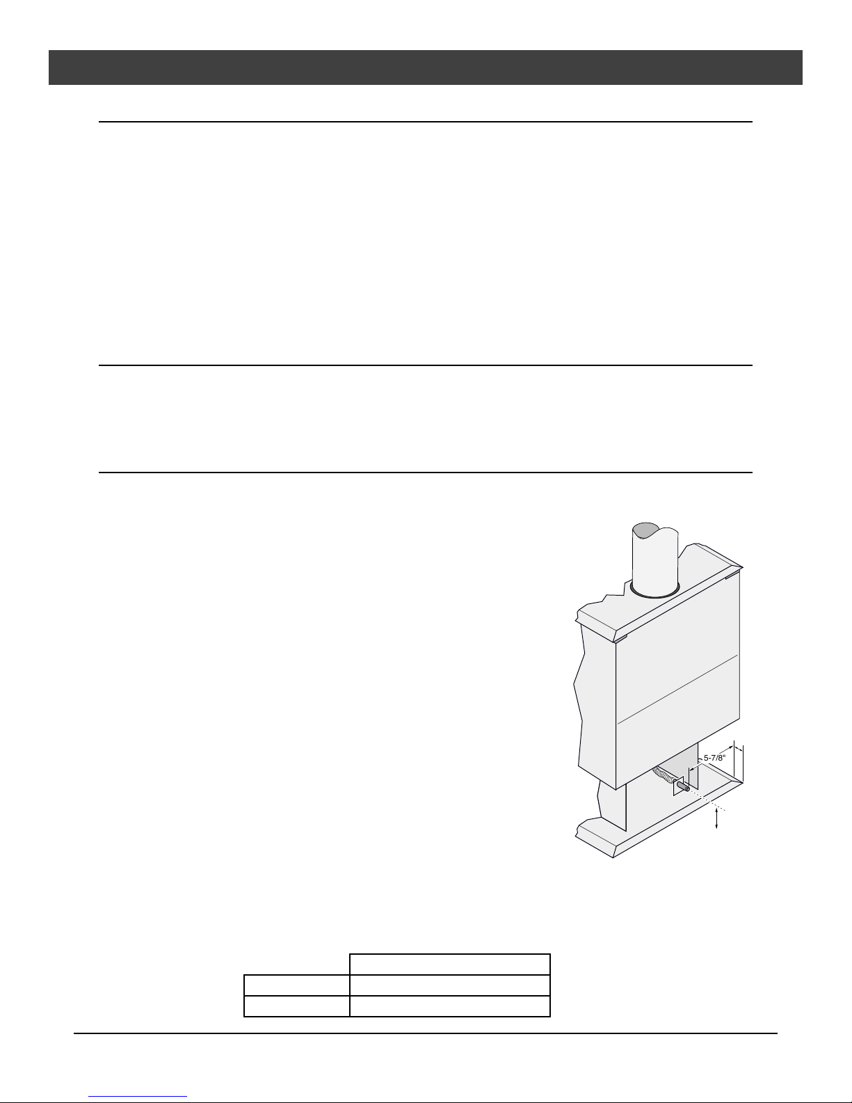
¥ The gas inlet accepts a 3/8Ó F.P.T. Fitting
¥ The location of the gas inlet is shown below
¥ A manual shutoff valve is required for installation (it must
be located within 3Õ (910 mm) of the heater)
Gas Inlet Pressure
¥ With the heater off, the inlet pressure must meet the
requirements listed in the table below
? If the pressure is not sufficient, make sure the piping used is large enough and the total
gas load for the residence does not exceed the amount supplied.
? The supply regulator (the regulator that attaches directly to the residence inlet or to the
propane tank) should supply gas at the suggested input pressure listed below. Contact
the local gas supplier if the regulator is at an improper pressure.
Standard Input Pressure
Natural Gas 7Ó W.C. (1.74 Kpa)
Propane 11Ó W.C. (2.73 Kpa)
1/4"
5-7/8"
3"
Travis Industries 93508102 091002
8 Installation (for qualified installers only)
Vent Requirements
! Always maintain the required 1Ó (25 mm) clearance (air space) to combustible materials to prevent a fire
hazard. Do not fill air spaces with insulation.
! The gas appliance and vent system must be vented directly to the outside of the building, and never
be attached to a chimney serving a separate solid fuel or gas-burning appliance. Each direct vent gas
appliance must use itÕs own separate vent system.
Altitude Considerations
This heater has been tested at altitudes
ranging from sea level to 8,000 feet
(2,400 M). In this testing we have found
that the heater, with its standard orifice,
burns correctly with just an air shutter
adjustment.
! Failure to adjust the air shutter properly
may lead to improper combustion which
can create a safety hazard. Consult your
dealer or installer if you suspect an
improperly adjusted air shutter.
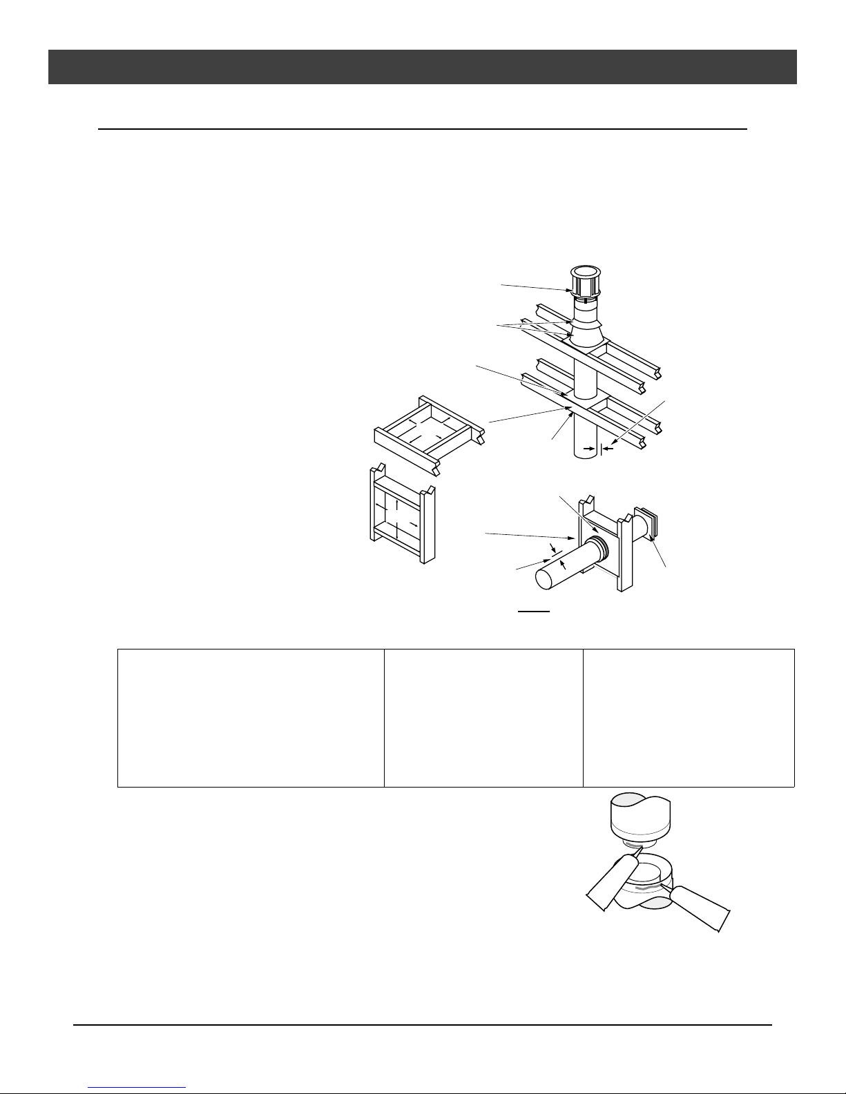
¥ When the vent passes through a wall,
a wall thimble is required. When the
vent passes through a ceiling, a
support box or firestop is required.
When the vent passes through the
roof, a roof flashing and storm collar
are required. Follow the instructions
Use a roof flashing and storm collar
whenever passing through the roof
(Duravent Part #953 & #943 or #943S)
Vertical Termination
(Duravent Part # 991)
Use a firestop spacer whenever
passing through a ceiling
(Duravent Part #963)
Minimum framing
for fire stop
8-5/8"
(220 mm)
8-5/8"
(220 mm)
Minimum
Framing for
wall thimble
Use a support box
on exposed vent
Use a wall thimble
whenever passing
through a wall
(Duravent Part #942)
Vertical Vent
Requirements
Maintain a minimum 1"
(25 mm) clearance from
vent to any combustible
(vent is 6 5/8" (170 mm)
diameter)
Horizontal Vent
Requirements
provided with the vent (from
Duravent¨) for installing these items.
Maintain a minimum 1" (25 mm)
clearance from vent to any combustible
(vent is 6 5/8" (170 mm) diameter)
Horizontal Termination
(Duravent Part #984)
¥ Use Model GS Direct Vent manufactured by Simpson Dura-Vent only (or the Chimney Conversion Kit
- see Addendum #2). Follow the installation instructions included with the vent. For the nearest
Simpson Dura-Vent supplier, call (800) 835-4429. Part numbers and descriptions are listed below.
Straight Lengths
908B 6Ó Pipe Length, Black (interior)
907B 9Ó Pipe Length, Black (interior)
906 12Ó Pipe Length, Galvanized
906B 12Ó Pipe Length, Black (interior)
904 24Ó Pipe Length, Galvanized
904B 24Ó Pipe Length, Black (interior)
903 36Ó Pipe Length, Galvanized
903B 36Ó Pipe Length, Black (interior)
902 48Ó Pipe Length, Galvanized
902B 48Ó Pipe Length, Black (interior)
911B 11Ó to 14 5/8Ó Pipe, Adjustable, Black (interior)
¥ Apply high-temperature silicone to the inner and outer pipe before
assembling the sections (on the male, upper section). This seals the
inner pipe from the outer pipe. Slide the sections together and turn 1/4
turn until the sections lock in place. Install three metal screws through
each joint to lock the outer section in place (see the instructions included
Vent Terminations
981 Snorkel Termination (36Ó rise)
(for basement installations)
982 Snorkel Termination (14Ó rise)
(for basement installations)
984 Horizontal Square Termination
950 Vinyl Siding Standoff
991 Vertical Termination
Elbows
990 90¥ Elbow
990B 90¥ Elbow, Black (interior)
945 45¡ Elbow
945B 45¡ Elbow, Black (interior)
Penetration, Support Parts
942 Wall Thimble
940 Optional Wall Thimble Cover
941 Cathedral Ceiling Support Box
943 Flashing, 0/12 to 6/12 Roof Pitch
943S Flashing, 7/12 to 12/12 Roof
Pitch
953 Storm Collar
963 Ceiling Firestop
988 Wall Strap
Apply a 1/8" (3 mm)
bead of hightemperature silicone
to the inner and
outer pipe. The
silicone must seal
the inner pipe from
the outer pipe.
with the vent for further details).
NOTE: You may screw the first section of vent to the appliance.
Silicone
Silicone
¥ Horizontal sections require a 1/4Ó rise every 12Ó of travel
+ Exterior Vent Diameter = 6-5/8Ó , Inner Vent Diameter = 4Ó
¥ Horizontal sections require non-combustible support every 36Ó (e.g.: use plumbing tape)
Travis Industries 93508102 091002
Installation (for qualified installers only) 9
Approved Vent Configurations
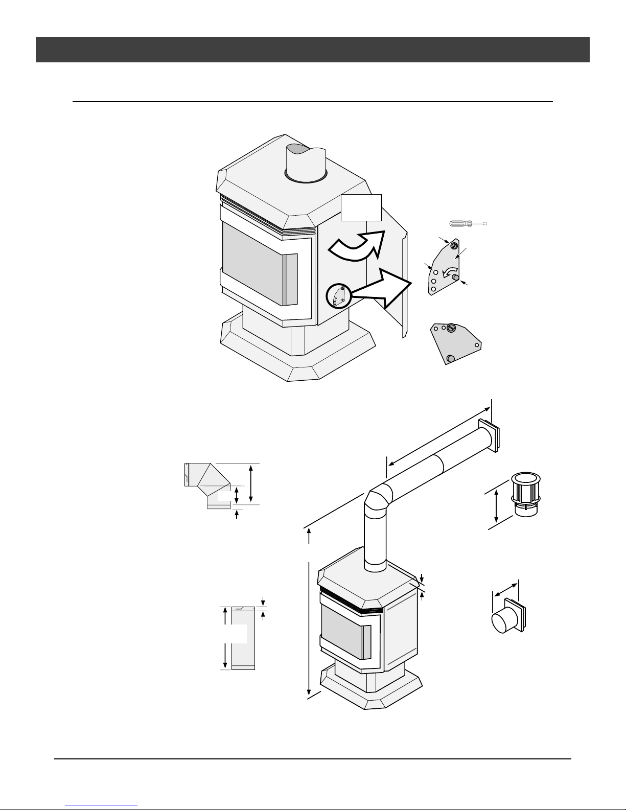
Restrictor Position
¥ A vent restrictor is built
into the appliance to
control the flow rate of
exhaust gases. This
ensures proper flames
for the wide variety of
vent configurations. The
restrictor consists of a
butterfly valve in the air
inlet and an adjustment
plate with index holes
used to hold the valve in
a fixed position.
Depending upon the
vent configuration, you
may be required to adjust
the restrictor position.
The charts for approved
vent configurations
describe which position
the vent restrictor must
be in.
Elbows
¥ 2 Elbow
maximum
(two 45¡ or
two 90¡, not one
45¡ and one 90¡)
Measuring
Vent Lengths
Elbows add 3" to the length of
the vent system.
Side
View
9-5/8"
3"
1-1/2"
1
Swing the
right side
door open.
Vent Height is
calculated to the
top of the vent on
horizontal
terminations and
to the top of the
termination on
vertical
terminations.
To Adjust the Restrictor:
Determine the correct restrictor position (see the charts
under "Approved Vent Configurations" - the stock
position is #1). Swing the left access panel open.
NOTE:
Position #1 is the
fully open position
Vent Horizontal Run
(measure from the closest
edge of the starter section to
the end of the termination)
Remove the screw with a 1/4"
2
nutdriver (or screwdriver).
Rotate the adjustment plate
3
counter-clockwise until the correct
index hole is above the pivot point.
Insert the screw into the correct
4
index hole and tighten.
1/4" Nutdriver
Screw
Index
Holes
The four holes on the restrictor
plate correspond to the four
restrictor positions.
This restrictor is
in Position #2.
12-3/8" tall with
1-1/2" of overlap
Adjustment
1
2
3
4
Pivot
Point
Plate
Vent sections overlap each
other by 1-1/2"
Vent Length
(3', 4', etc.)
Travis Industries 93508102 091002
1-1/2"
Vent
Height
8-3/4" wide with 1-1/2"
to 3-3/8" of overlap
The starter
section is 1-1/2"
above the top
10 Installation (for qualified installers only)
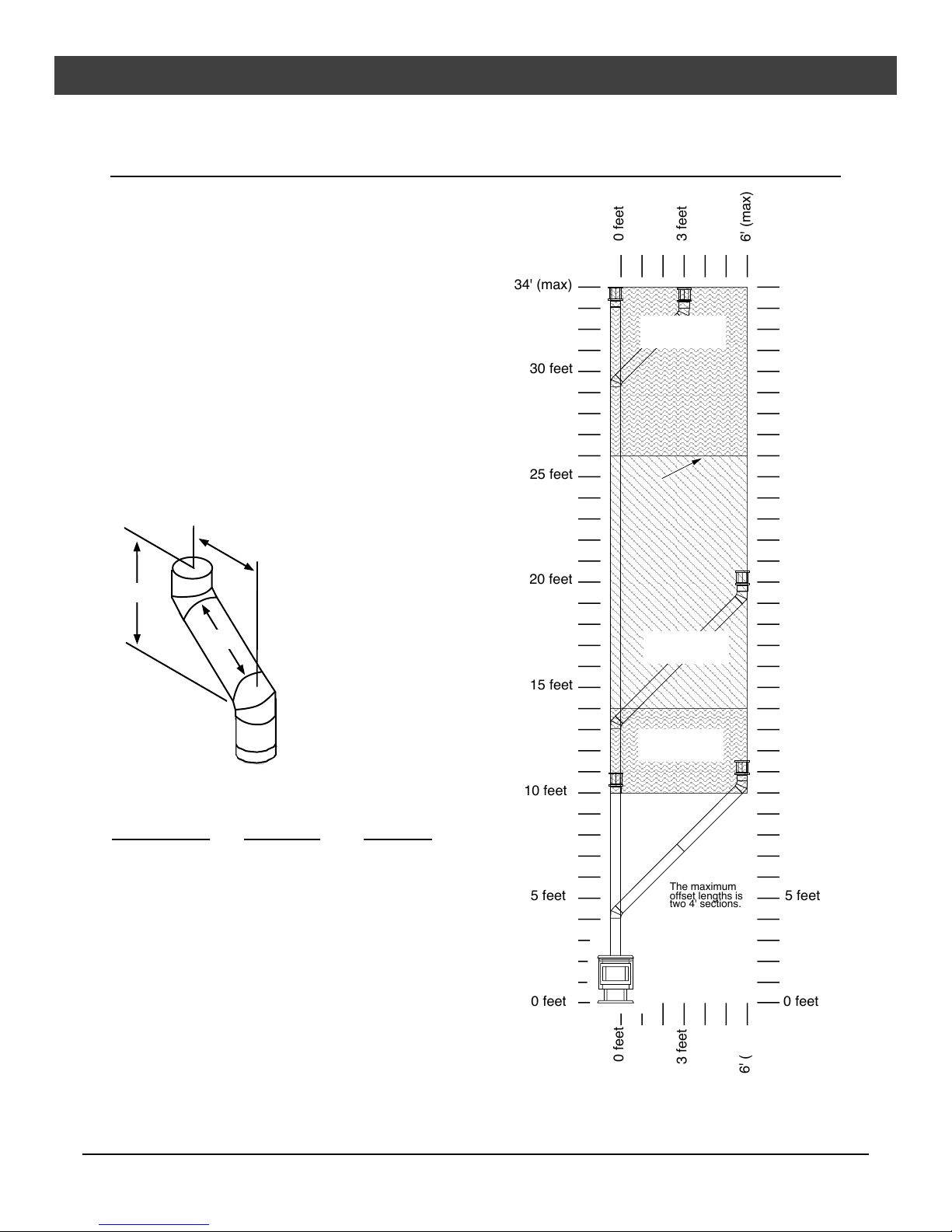
Approved Venting Configurations for Vertical Terminations with
(or without) Two 45¡ Elbows
¥ 10Õ Minimum System Height
(with or without offsets)
¥ 34Õ Maximum System Height
¥ 6Õ Maximum Offset
¥ The termination must fall within the shaded area
shown in the chart. Use the indicated restrictor
position.
¥ If using offsets, use the table below to calculate
the vertical rise and horizontal offset
Horizontal
Offset
Vertical
Rise
Offset
Length
34' (max)
30 feet
25 feet
20 feet
0 feet
3 feet
Restrictor
Position # 4
NOTE:
Restrictor positions
are based upon lab
tests. The ideal
restrictor position
may vary slightly,
especially when the
termination is near a
demarkation line.
Restrictor
Position # 3
6' (max)
34' (max)
30 feet
25 feet
20 feet
15 feet
15 feet
Restrictor
Position # 2
10 feet
Offset Length
Hor. Offset
10 feet
Vert. Rise
None 5Ó 1Õ
1Õ Section 1Õ 1Õ 7Ó
5 feet
2Õ Section 1Õ 9Ó 2Õ 4Ó
The maximum
offset lengths is
two 4' sections.
5 feet
3Õ Section 2Õ 5Ó 3Õ
4Õ Section 3Õ 2Ó 3Õ 8Ó
4Õ + 1Õ Section 3Õ 9Ó 4Õ 4Ó
0 feet
0 feet
4Õ + 2Õ Section 4Õ 6Ó 5Õ
4Õ + 3Õ Section 5Õ 2Ó 5Õ 9Ó
4Õ + 4Õ Section 6Õ 6Õ 9Ó
0 feet
3 feet
6' (max)
Travis Industries 93508102 091002
Installation (for qualified installers only) 11
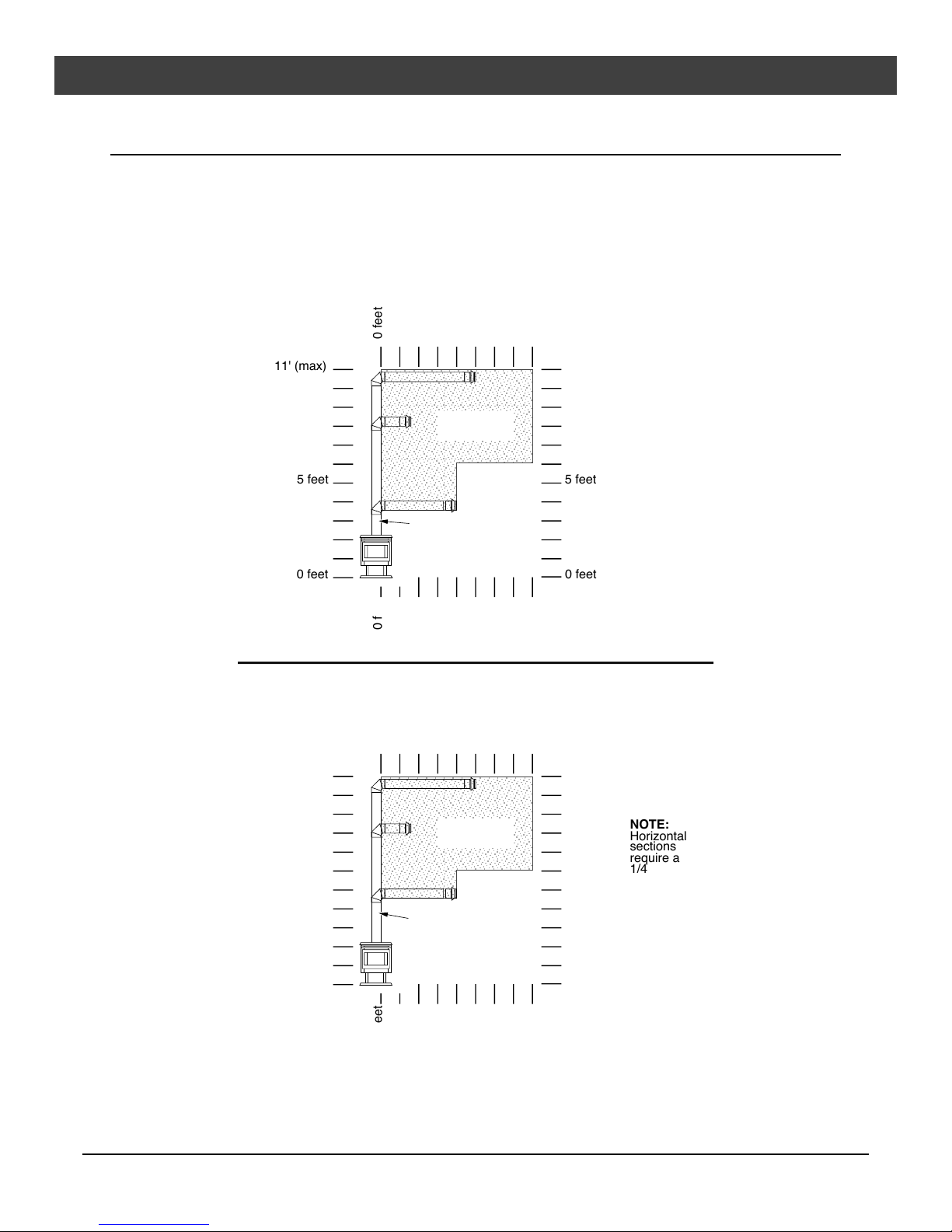
Approved Venting Configurations with a Horizontal Termination
¥ If using a Snorkel Termination (14Ó or 36Ó) add the snorkel height to the vertical height (snorkel
terminations are used primarily for basement installations).
¥ The termination must fall within the shaded area shown in the chart. Use the indicated restrictor
position.
Natural Gas
0 feet
11' (max)
5 feet
0 feet
0 feet
Propane (LP)
0 feet
11' (max)
Position # 1
Min. 1'
Vertical
Section
5 feet
Restrictor
5 feet
5 feet
8' (max)
11' (max)
5 feet
0 feet
8'(max)
8' (max)
11' (max)
NOTE:
Horizontal
sections
require a
1/4" rise
every 12" of
travel.
5 feet
0 feet
Travis Industries 93508102 091002
0 feet
Position # 1
Min. 2'
Vertical
Section
Restrictor
5 feet
5 feet
0 feet
8'(max)
NOTE:
Horizontal
sections
require a
1/4" rise
every 12" of
travel.

12 Installation (for qualified installers only)
Approved Venting Configurations for Vertical Terminations with
Two 90¡ Elbows
¥ The termination must fall within the shaded area shown in the chart. Use the indicated restrictor
position.
34' (max)
30 feet
25 feet
20 feet
15 feet
0 feet
5 feet
Position # 4
Restrictor
Position # 3
Restrictor
NOTE:
Restrictor positions are
based upon lab tests.
The ideal restrictor
position may vary
slightly, especially when
the termination is near a
demarkation line.
10 feet
16'(max)
34' (max)
30 feet
25 feet
20 feet
15 feet
10 feet
(min.)
5 feet
0 feet
Travis Industries 93508102 091002
NOTE:
Horizontal sections require a 1/4" (6 mm)
rise every 12" (300 mm) of travel.
0 feet
5 feet
(1.5 M)
(3 M)
10 feet
10 feet
(min.)
5 feet
0 feet
(4.9 M)
16'(max)
 Loading...