


 Loading...
Syncro® CS 9286-8e Solution
User Guide
Version 3.0
November 2014
DB15-001017-02
DB15-001017-02

Syncro CS 9286-8e Solution User Guide
November 2014
For a comprehensive list of changes to this document, see the Revision History.
Corporate Headquarters |
Website |
|
San Jose, CA |
globalsupport.pdl@avagotech.com |
www.lsi.com |
800-372-2447 |
|
|
Avago, Avago Technologies, the A logo, LSI, Storage by LSI, CacheCade, CacheVault, Dimmer Switch, MegaRAID, MegaRAID Storage Manager, and Syncro are trademarks of Avago Technologies in the United States and other countries. All other brand and product names may be trademarks of their respective companies.
Data subject to change. Copyright © 2013–2014 Avago Technologies. All Rights Reserved.

Syncro CS 9286-8e Solution User Guide |
Table of Contents |
November 2014 |
|
Table of Contents
Chapter 1: Introduction . . . . . . . . . . . . . . . . . . . . . . . . . . . . . . . . . . . . . . . . . . . . . . . . . . . . . . . . . . . . . . . . . . . . . . . . . . . . . . . . . . . . . . . . . . . . . . . . . . . . . . . . . 5
1.1 Concepts of High-Availability DAS . . . . . . . . . . . . . . . . . . . . . . . . . . . . . . . . . . . . . . . . . . . . . . . . . . . . . . . . . . . . . . . . . . . . . . . . . . . . . . . . . . . . . . . . . . . . . . . . . . . 5
1.2 HA-DAS Terminology . . . . . . . . . . . . . . . . . . . . . . . . . . . . . . . . . . . . . . . . . . . . . . . . . . . . . . . . . . . . . . . . . . . . . . . . . . . . . . . . . . . . . . . . . . . . . . . . . . . . . . . . . . . . . . . 6
1.3 Syncro CS 9286-8e Solution Features . . . . . . . . . . . . . . . . . . . . . . . . . . . . . . . . . . . . . . . . . . . . . . . . . . . . . . . . . . . . . . . . . . . . . . . . . . . . . . . . . . . . . . . . . . . . . . . . 6
1.4 Hardware Compatibility . . . . . . . . . . . . . . . . . . . . . . . . . . . . . . . . . . . . . . . . . . . . . . . . . . . . . . . . . . . . . . . . . . . . . . . . . . . . . . . . . . . . . . . . . . . . . . . . . . . . . . . . . . . . . 7
1.5 Overview of the Cluster Setup and Configuration . . . . . . . . . . . . . . . . . . . . . . . . . . . . . . . . . . . . . . . . . . . . . . . . . . . . . . . . . . . . . . . . . . . . . . . . . . . . . . . . . . . . 7
1.6 Performance Considerations . . . . . . . . . . . . . . . . . . . . . . . . . . . . . . . . . . . . . . . . . . . . . . . . . . . . . . . . . . . . . . . . . . . . . . . . . . . . . . . . . . . . . . . . . . . . . . . . . . . . . . . . 7
Chapter 2: Hardware and Software Setup . . . . . . . . . . . . . . . . . . . . . . . . . . . . . . . . . . . . . . . . . . . . . . . . . . . . . . . . . . . . . . . . . . . . . . . . . . . . . . . . . . . . . . . . 9
2.1 Syncro CS 9286-8e Two-Server Cluster Hardware Setup . . . . . . . . . . . . . . . . . . . . . . . . . . . . . . . . . . . . . . . . . . . . . . . . . . . . . . . . . . . . . . . . . . . . . . . . . . . . . 10 2.2 Cabling Configurations . . . . . . . . . . . . . . . . . . . . . . . . . . . . . . . . . . . . . . . . . . . . . . . . . . . . . . . . . . . . . . . . . . . . . . . . . . . . . . . . . . . . . . . . . . . . . . . . . . . . . . . . . . . . 15
Chapter 3: Creating the Cluster . . . . . . . . . . . . . . . . . . . . . . . . . . . . . . . . . . . . . . . . . . . . . . . . . . . . . . . . . . . . . . . . . . . . . . . . . . . . . . . . . . . . . . . . . . . . . . . . . 18
3.1 Creating Virtual Drives on the Controller Nodes . . . . . . . . . . . . . . . . . . . . . . . . . . . . . . . . . . . . . . . . . . . . . . . . . . . . . . . . . . . . . . . . . . . . . . . . . . . . . . . . . . . . . |
18 |
3.1.1 Creating Shared or Exclusive VDs with the WebBIOS Utility . . . . . . . . . . . . . . . . . . . . . . . . . . . . . . . . . . . . . . . . . . . . . . . . . . . . . . . . . . . . . . . . . . . |
18 |
3.1.2 Creating Shared or Exclusive VDs with StorCLI . . . . . . . . . . . . . . . . . . . . . . . . . . . . . . . . . . . . . . . . . . . . . . . . . . . . . . . . . . . . . . . . . . . . . . . . . . . . . . . . |
21 |
3.1.3 Creating Shared or Exclusive VDs with MegaRAID Storage Manager . . . . . . . . . . . . . . . . . . . . . . . . . . . . . . . . . . . . . . . . . . . . . . . . . . . . . . . . . . . |
22 |
3.1.3.1 Unsupported Drives . . . . . . . . . . . . . . . . . . . . . . . . . . . . . . . . . . . . . . . . . . . . . . . . . . . . . . . . . . . . . . . . . . . . . . . . . . . . . . . . . . . . . . . . . . . . . . . . . . |
24 |
3.2 HA-DAS CacheCade Support . . . . . . . . . . . . . . . . . . . . . . . . . . . . . . . . . . . . . . . . . . . . . . . . . . . . . . . . . . . . . . . . . . . . . . . . . . . . . . . . . . . . . . . . . . . . . . . . . . . . . . . |
24 |
3.3 Creating the Cluster in Windows . . . . . . . . . . . . . . . . . . . . . . . . . . . . . . . . . . . . . . . . . . . . . . . . . . . . . . . . . . . . . . . . . . . . . . . . . . . . . . . . . . . . . . . . . . . . . . . . . . . |
27 |
3.3.1 Prerequisites for Cluster Setup . . . . . . . . . . . . . . . . . . . . . . . . . . . . . . . . . . . . . . . . . . . . . . . . . . . . . . . . . . . . . . . . . . . . . . . . . . . . . . . . . . . . . . . . . . . . . . . |
27 |
3.3.1.1 Clustered RAID Controller Support . . . . . . . . . . . . . . . . . . . . . . . . . . . . . . . . . . . . . . . . . . . . . . . . . . . . . . . . . . . . . . . . . . . . . . . . . . . . . . . . . . . . |
27 |
3.3.1.2 Enable Failover Clustering . . . . . . . . . . . . . . . . . . . . . . . . . . . . . . . . . . . . . . . . . . . . . . . . . . . . . . . . . . . . . . . . . . . . . . . . . . . . . . . . . . . . . . . . . . . . |
27 |
3.3.1.3 Configure Network Settings . . . . . . . . . . . . . . . . . . . . . . . . . . . . . . . . . . . . . . . . . . . . . . . . . . . . . . . . . . . . . . . . . . . . . . . . . . . . . . . . . . . . . . . . . . . |
28 |
3.3.2 Creating the Failover Cluster . . . . . . . . . . . . . . . . . . . . . . . . . . . . . . . . . . . . . . . . . . . . . . . . . . . . . . . . . . . . . . . . . . . . . . . . . . . . . . . . . . . . . . . . . . . . . . . . . |
29 |
3.3.3 Validating the Failover Cluster Configuration . . . . . . . . . . . . . . . . . . . . . . . . . . . . . . . . . . . . . . . . . . . . . . . . . . . . . . . . . . . . . . . . . . . . . . . . . . . . . . . . . |
29 |
3.4 Creating the Cluster in Red Hat Enterprise Linux (RHEL) . . . . . . . . . . . . . . . . . . . . . . . . . . . . . . . . . . . . . . . . . . . . . . . . . . . . . . . . . . . . . . . . . . . . . . . . . . . . . |
30 |
3.4.1 Prerequisites for Cluster Setup . . . . . . . . . . . . . . . . . . . . . . . . . . . . . . . . . . . . . . . . . . . . . . . . . . . . . . . . . . . . . . . . . . . . . . . . . . . . . . . . . . . . . . . . . . . . . . . |
30 |
3.4.1.1 Configure Network Settings . . . . . . . . . . . . . . . . . . . . . . . . . . . . . . . . . . . . . . . . . . . . . . . . . . . . . . . . . . . . . . . . . . . . . . . . . . . . . . . . . . . . . . . . . . . |
30 |
3.4.1.2 Install and Configure the High Availability Add-On Features . . . . . . . . . . . . . . . . . . . . . . . . . . . . . . . . . . . . . . . . . . . . . . . . . . . . . . . . . . . . |
31 |
3.4.1.3 Configure SELinux . . . . . . . . . . . . . . . . . . . . . . . . . . . . . . . . . . . . . . . . . . . . . . . . . . . . . . . . . . . . . . . . . . . . . . . . . . . . . . . . . . . . . . . . . . . . . . . . . . . . |
32 |
3.4.2 Creating the Cluster . . . . . . . . . . . . . . . . . . . . . . . . . . . . . . . . . . . . . . . . . . . . . . . . . . . . . . . . . . . . . . . . . . . . . . . . . . . . . . . . . . . . . . . . . . . . . . . . . . . . . . . . . |
32 |
3.4.3 Configure the Logical Volumes and Apply GFS2 File System . . . . . . . . . . . . . . . . . . . . . . . . . . . . . . . . . . . . . . . . . . . . . . . . . . . . . . . . . . . . . . . . . . |
33 |
3.4.4 Add a Fence Device . . . . . . . . . . . . . . . . . . . . . . . . . . . . . . . . . . . . . . . . . . . . . . . . . . . . . . . . . . . . . . . . . . . . . . . . . . . . . . . . . . . . . . . . . . . . . . . . . . . . . . . . . |
34 |
3.4.5 Create a Failover Domain . . . . . . . . . . . . . . . . . . . . . . . . . . . . . . . . . . . . . . . . . . . . . . . . . . . . . . . . . . . . . . . . . . . . . . . . . . . . . . . . . . . . . . . . . . . . . . . . . . . . |
35 |
3.4.6 Add Resources to the Cluster . . . . . . . . . . . . . . . . . . . . . . . . . . . . . . . . . . . . . . . . . . . . . . . . . . . . . . . . . . . . . . . . . . . . . . . . . . . . . . . . . . . . . . . . . . . . . . . . |
36 |
3.4.7 Create Service Groups . . . . . . . . . . . . . . . . . . . . . . . . . . . . . . . . . . . . . . . . . . . . . . . . . . . . . . . . . . . . . . . . . . . . . . . . . . . . . . . . . . . . . . . . . . . . . . . . . . . . . . . |
40 |
3.4.8 Mount the NFS Resource from the Remote Client . . . . . . . . . . . . . . . . . . . . . . . . . . . . . . . . . . . . . . . . . . . . . . . . . . . . . . . . . . . . . . . . . . . . . . . . . . . . . |
41 |
3.5 Creating the Cluster in SuSE Linux Enterprise Server (SLES) . . . . . . . . . . . . . . . . . . . . . . . . . . . . . . . . . . . . . . . . . . . . . . . . . . . . . . . . . . . . . . . . . . . . . . . . . . |
41 |
3.5.1 Prerequisites for Cluster Setup . . . . . . . . . . . . . . . . . . . . . . . . . . . . . . . . . . . . . . . . . . . . . . . . . . . . . . . . . . . . . . . . . . . . . . . . . . . . . . . . . . . . . . . . . . . . . . . |
41 |
3.5.1.1 Prepare the Operating System . . . . . . . . . . . . . . . . . . . . . . . . . . . . . . . . . . . . . . . . . . . . . . . . . . . . . . . . . . . . . . . . . . . . . . . . . . . . . . . . . . . . . . . . |
41 |
3.5.1.2 Configure Network Settings . . . . . . . . . . . . . . . . . . . . . . . . . . . . . . . . . . . . . . . . . . . . . . . . . . . . . . . . . . . . . . . . . . . . . . . . . . . . . . . . . . . . . . . . . . . |
42 |
3.5.1.3 Connect to the NTP Server for Time Synchronization . . . . . . . . . . . . . . . . . . . . . . . . . . . . . . . . . . . . . . . . . . . . . . . . . . . . . . . . . . . . . . . . . . . |
44 |
3.5.2 Creating the Cluster . . . . . . . . . . . . . . . . . . . . . . . . . . . . . . . . . . . . . . . . . . . . . . . . . . . . . . . . . . . . . . . . . . . . . . . . . . . . . . . . . . . . . . . . . . . . . . . . . . . . . . . . . |
45 |
3.5.2.1 Cluster Setup . . . . . . . . . . . . . . . . . . . . . . . . . . . . . . . . . . . . . . . . . . . . . . . . . . . . . . . . . . . . . . . . . . . . . . . . . . . . . . . . . . . . . . . . . . . . . . . . . . . . . . . . . |
45 |
3.5.3 Bringing the Cluster Online . . . . . . . . . . . . . . . . . . . . . . . . . . . . . . . . . . . . . . . . . . . . . . . . . . . . . . . . . . . . . . . . . . . . . . . . . . . . . . . . . . . . . . . . . . . . . . . . . . |
50 |
3.5.4 Configuring the NFS Resource with STONITH SBD Fencing . . . . . . . . . . . . . . . . . . . . . . . . . . . . . . . . . . . . . . . . . . . . . . . . . . . . . . . . . . . . . . . . . . . . |
50 |
3.5.4.1 Install NFSSERVER . . . . . . . . . . . . . . . . . . . . . . . . . . . . . . . . . . . . . . . . . . . . . . . . . . . . . . . . . . . . . . . . . . . . . . . . . . . . . . . . . . . . . . . . . . . . . . . . . . . . |
50 |
3.5.4.2 Configure the Partition and the File System . . . . . . . . . . . . . . . . . . . . . . . . . . . . . . . . . . . . . . . . . . . . . . . . . . . . . . . . . . . . . . . . . . . . . . . . . . . . |
50 |
3.5.4.3 Configure stonith_sbd Fencing . . . . . . . . . . . . . . . . . . . . . . . . . . . . . . . . . . . . . . . . . . . . . . . . . . . . . . . . . . . . . . . . . . . . . . . . . . . . . . . . . . . . . . . |
51 |
3.5.5 Adding NFS Cluster Resources . . . . . . . . . . . . . . . . . . . . . . . . . . . . . . . . . . . . . . . . . . . . . . . . . . . . . . . . . . . . . . . . . . . . . . . . . . . . . . . . . . . . . . . . . . . . . . . |
53 |
3.5.6 Mounting NFS in the Remote Client . . . . . . . . . . . . . . . . . . . . . . . . . . . . . . . . . . . . . . . . . . . . . . . . . . . . . . . . . . . . . . . . . . . . . . . . . . . . . . . . . . . . . . . . . . |
56 |
Avago Technologies
- 3 -

Syncro CS 9286-8e Solution User Guide |
Table of Contents |
November 2014 |
|
Chapter 4: System Administration . . . . . . . . . . . . . . . . . . . . . . . . . . . . . . . . . . . . . . . . . . . . . . . . . . . . . . . . . . . . . . . . . . . . . . . . . . . . . . . . . . . . |
. . . . . . . . . . 57 |
4.1 High Availability Properties . . . . . . . . . . . . . . . . . . . . . . . . . . . . . . . . . . . . . . . . . . . . . . . . . . . . . . . . . . . . . . . . . . . . . . . . . . . . . . . . . . . . . . . . . . . . . |
. . . . . . . . . . . 57 |
4.2 Understanding Failover Operations . . . . . . . . . . . . . . . . . . . . . . . . . . . . . . . . . . . . . . . . . . . . . . . . . . . . . . . . . . . . . . . . . . . . . . . . . . . . . . . . . . . . . |
. . . . . . . . . . . 58 |
4.2.1 Understanding and Using Planned Failover . . . . . . . . . . . . . . . . . . . . . . . . . . . . . . . . . . . . . . . . . . . . . . . . . . . . . . . . . . . . . . . . . . . . . . . |
. . . . . . . . . . . 60 |
4.2.1.1 Planned Failover in Windows Server 2012 . . . . . . . . . . . . . . . . . . . . . . . . . . . . . . . . . . . . . . . . . . . . . . . . . . . . . . . . . . . . . . . . . . |
. . . . . . . . . . . 60 |
4.2.1.2 Planned Failover in Windows Server 2008 R2 . . . . . . . . . . . . . . . . . . . . . . . . . . . . . . . . . . . . . . . . . . . . . . . . . . . . . . . . . . . . . . . |
. . . . . . . . . . . 61 |
4.2.1.3 Planned Failover in Red Hat Enterprise Linux . . . . . . . . . . . . . . . . . . . . . . . . . . . . . . . . . . . . . . . . . . . . . . . . . . . . . . . . . . . . . . . |
. . . . . . . . . . . 63 |
4.2.2 Understanding Unplanned Failover . . . . . . . . . . . . . . . . . . . . . . . . . . . . . . . . . . . . . . . . . . . . . . . . . . . . . . . . . . . . . . . . . . . . . . . . . . . . . . . |
. . . . . . . . . . . 63 |
4.3 Updating the Syncro CS 9286-8e Controller Firmware . . . . . . . . . . . . . . . . . . . . . . . . . . . . . . . . . . . . . . . . . . . . . . . . . . . . . . . . . . . . . . . . . . . . |
. . . . . . . . . . . 64 |
4.4 Updating the MegaRAID Driver . . . . . . . . . . . . . . . . . . . . . . . . . . . . . . . . . . . . . . . . . . . . . . . . . . . . . . . . . . . . . . . . . . . . . . . . . . . . . . . . . . . . . . . . . |
. . . . . . . . . . . 64 |
4.4.1 Updating the MegaRAID Driver in Windows Server 2008 R2 . . . . . . . . . . . . . . . . . . . . . . . . . . . . . . . . . . . . . . . . . . . . . . . . . . . . . . . . |
. . . . . . . . . . . 65 |
4.4.2 Updating the MegaRAID Driver in Windows Server 2012 . . . . . . . . . . . . . . . . . . . . . . . . . . . . . . . . . . . . . . . . . . . . . . . . . . . . . . . . . . . |
. . . . . . . . . . . 67 |
4.4.3 Updating the Red Hat Linux System Driver . . . . . . . . . . . . . . . . . . . . . . . . . . . . . . . . . . . . . . . . . . . . . . . . . . . . . . . . . . . . . . . . . . . . . . . . |
. . . . . . . . . . . 68 |
4.4.4 Updating the SuSE Linux Enterprise Server 11 Driver . . . . . . . . . . . . . . . . . . . . . . . . . . . . . . . . . . . . . . . . . . . . . . . . . . . . . . . . . . . . . . |
. . . . . . . . . . . 68 |
4.5 Performing Preventive Measures on Disk Drives and VDs . . . . . . . . . . . . . . . . . . . . . . . . . . . . . . . . . . . . . . . . . . . . . . . . . . . . . . . . . . . . . . . . . |
. . . . . . . . . . . 69 |
Chapter 5: Troubleshooting . . . . . . . . . . . . . . . . . . . . . . . . . . . . . . . . . . . . . . . . . . . . . . . . . . . . . . . . . . . . . . . . . . . . . . . . . . . . . . . . . . . . . . . . . . . . . . . . . . . . 70
5.1 Verifying HA-DAS Support in Tools and the OS Driver . . . . . . . . . . . . . . . . . . . . . . . . . . . . . . . . . . . . . . . . . . . . . . . . . . . . . . . . . . . . . . . . . . . . . . . . . . . . . . . 70 5.2 Confirming SAS Connections . . . . . . . . . . . . . . . . . . . . . . . . . . . . . . . . . . . . . . . . . . . . . . . . . . . . . . . . . . . . . . . . . . . . . . . . . . . . . . . . . . . . . . . . . . . . . . . . . . . . . . . 71 5.2.1 Using WebBIOS to View Connections for Controllers, Expanders, and Drives . . . . . . . . . . . . . . . . . . . . . . . . . . . . . . . . . . . . . . . . . . . . . . . . . . . 71 5.2.2 Using WebBIOS to Verify Dual-Ported SAS Addresses to Disk Drives . . . . . . . . . . . . . . . . . . . . . . . . . . . . . . . . . . . . . . . . . . . . . . . . . . . . . . . . . . . 72 5.2.3 Using StorCLI to Verify Dual-Ported SAS Addresses to Disk Drives . . . . . . . . . . . . . . . . . . . . . . . . . . . . . . . . . . . . . . . . . . . . . . . . . . . . . . . . . . . . . 73 5.2.4 Using MegaRAID Storage Manager to Verify Dual-Ported SAS Addresses to Disk Drives . . . . . . . . . . . . . . . . . . . . . . . . . . . . . . . . . . . . . . . . 74 5.3 Understanding CacheCade Behavior During a Failover . . . . . . . . . . . . . . . . . . . . . . . . . . . . . . . . . . . . . . . . . . . . . . . . . . . . . . . . . . . . . . . . . . . . . . . . . . . . . . 74
5.4 Error Situations and Solutions . . . . . . . . . . . . . . . . . . . . . . . . . . . . . . . . . . . . . . . . . . . . . . . . . . . . . . . . . . . . . . . . . . . . . . . . . . . . . . . . . . . . . . . . . . . . . . . . . . . . . . 75 5.5 Event Messages and Error Messages . . . . . . . . . . . . . . . . . . . . . . . . . . . . . . . . . . . . . . . . . . . . . . . . . . . . . . . . . . . . . . . . . . . . . . . . . . . . . . . . . . . . . . . . . . . . . . . . 76 5.5.1 Error Level Meaning . . . . . . . . . . . . . . . . . . . . . . . . . . . . . . . . . . . . . . . . . . . . . . . . . . . . . . . . . . . . . . . . . . . . . . . . . . . . . . . . . . . . . . . . . . . . . . . . . . . . . . . . . 76
Revision History . . . . . . . . . . . . . . . . . . . . . . . . . . . . . . . . . . . . . . . . . . . . . . . . . . . . . . . . . . . . . . . . . . . . . . . . . . . . . . . . . . . . . . . . . . . . . . . . . . . . . . . . . . . . . . . 79
Avago Technologies
- 4 -

Syncro CS 9286-8e Solution User Guide |
Chapter 1: Introduction |
November 2014 |
Concepts of High-Availability DAS |
Chapter 1: Introduction
This document explains how to set up and configure the hardware and software for the Syncro® CS 9286-8e high-availability direct-attached storage (HA-DAS) solution.
The Syncro CS 9286-8e solution provides fault tolerance capabilities as a key part of a high-availability data storage system. The Syncro CS 9286-8e solution combines redundant servers, LSI® HA-DAS RAID controllers, computer nodes, cable connections, common SAS JBOD enclosures, and dual-ported SAS storage devices.
The redundant components and software technologies provide a high-availability system with ongoing service that is not interrupted by the following events:
The failure of a single internal node does not interrupt service because the solution has multiple nodes with cluster failover.
An expander failure does not interrupt service because the dual expanders in every enclosure provide redundant data paths.
A drive failure does not interrupt service because RAID fault tolerance is part of the configuration.
A system storage expansion or maintenance activity can be completed without requiring an interruption of service because of redundant components, management software, and maintenance procedures.
1.1Concepts of High-Availability DAS
In terms of data storage and processing, High Availability (HA) means a computer system design that ensures a high level of operational continuity and data access reliability over a long period of time. High-availability systems are critical to the success and business needs of small and medium-sized business (SMB) customers, such as retail outlets and health care offices, who cannot afford to have their computer systems go down. An HA-DAS solution enables customers to maintain continuous access to and use of their computer system. Shared direct-attached drives are accessible to multiple servers, thereby maintaining ease of use and reducing storage costs.
A cluster is a group of computers working together to run a common set of applications and to present a single logical system to the client and application. Failover clustering provides redundancy to the cluster group to maximize up-time by utilizing fault-tolerant components. In the example of two servers with shared storage that comprise a failover cluster, when a server fails, the failover cluster automatically moves control of the shared resources to the surviving server with no interruption of processing. This configuration allows seamless failover capabilities in the event of planned failover (maintenance mode) for maintenance or upgrade, or in the event of a failure of the CPU, memory, or other server failures.
Because multiple initiators exist in a clustered pair of servers (nodes) with a common shared storage domain, there is a concept of device reservations in which physical drives, drive groups, and virtual drives (VDs) are managed by a selected single initiator. For HA-DAS, I/O transactions and RAID management operations are normally processed by a single Syncro CS 9286-8e controller, and the associated physical drives, drive groups, and VDs are only visible to that controller. To assure continued operation, all other physical drives, drive groups, and VDs are also visible to, though not normally controlled by, the Syncro CS controller. This key functionality allows the Syncro CS solution to share VDs among multiple initiators as well as exclusively constrain VD access to a particular initiator without the need for SAS zoning.
Node downtime in an HA system can be either planned and unplanned. Planned node downtime is the result of management-initiated events, such as upgrades and maintenance. Unplanned node downtime results from events that are not within the direct control of IT administrators, such as failed software, drivers, or hardware. The Syncro CS 9286-8e solution protects your data and maintains system up-time from both planned and unplanned node downtime. It also enables you to schedule node downtime to update hardware or firmware, and so on. When you bring one controller node down for scheduled maintenance, the other node takes over with no interruption
of service.
Avago Technologies
- 5 -

Syncro CS 9286-8e Solution User Guide |
Chapter 1: Introduction |
November 2014 |
HA-DAS Terminology |
1.2HA-DAS Terminology
This section defines some additional important HA-DAS terms.
Cache Mirror: A cache coherency term that describes the duplication of write-back cached data across two controllers.
Exclusive Access: A host access policy in which a VD is only exposed to, and accessed by, a single specified server.
Failover: The process in which the management of drive groups and VDs transitions from one controller to the peer controller to maintain data access and availability.
HA Domain: A type of storage domain that consists of a set of HA controllers, cables, shared disk resources, and storage media.
Peer Controller: A relative term to describe the HA controller in the HA domain that acts as the failover controller.
Server/Controller Node: A processing entity composed of a single host processor unit or multiple host processor units that is characterized by having a single instance of a host operating system.
Server Storage Cluster: An HA storage topology in which a common pool of storage devices is shared by two computer nodes through dedicated Syncro CS 9286-8e controllers.
Shared Access: A host access policy in which a VD is exposed to, and can be accessed by, all servers in the HA domain.
Virtual Drive (VD): A storage unit created by a RAID controller from one or more physical drives. Although a virtual drive can consist of multiple drives, it is seen by the operating system as a single drive. Depending on the RAID level used, the virtual drive might retain redundant data in case of a drive failure.
1.3Syncro CS 9286-8e Solution Features
The Syncro CS 9286-8e solution supports the following HA features.
Server storage cluster topology, enabled by the following supported operating systems:
—Microsoft® Windows Server® 2008 R2
—Microsoft Windows Server 2012
—Red Hat® Enterprise Linux® 6.3
—Red Hat Enterprise Linux 6.4
—SuSE® Linux Enterprise Server 11 SP3
—SuSE Linux Enterprise Server 11 SP2
Clustering/HA services support:
—Microsoft failover clustering
—Red Hat High Availability Add-on
—SuSE High Availability Extensions
Dual-active HA with shared storage
Controller-to-controller intercommunication over SAS
Write-back cache coherency
CacheCade® 1.0 (Read)
Shared and exclusive VD I/O access policies
Operating system boot from the controller (exclusive access)
Controller hardware and property mismatch detection, handling, and reporting
Global hot spare support for all volumes in the HA domain
Planned and unplanned failover modes
CacheVault® provides cache cached data protection in case of host power loss or server failure
Avago Technologies
- 6 -

Syncro CS 9286-8e Solution User Guide |
Chapter 1: Introduction |
November 2014 |
Hardware Compatibility |
Full MegaRAID® features, with the following exceptions.
—T10 Data Integrity Field (DIF) is not supported.
—Self-encrypting drives (SEDs) and full disk encryption (FDE) are not supported.
—CacheCade 2.0 (write back) is not supported.
—Dimmer Switch® is not supported.
—SGPIO sideband signaling for enclosure management is not supported.
1.4Hardware Compatibility
The servers, disk drives, and JBOD enclosures that you use in the Syncro CS 9286-8e solution must be selected from the list of approved components that LSI has tested for compatibility. Refer to the web page for the compatibility lists at http://www.lsi.com/channel/support/pages/interoperability.aspx.
1.5Overview of the Cluster Setup and Configuration
Chapter 2 and Chapter 3 describe how to install the hardware and software so that you can use the fault tolerance capabilities of HA-DAS to provide continuous service in event of drive failure or server failure, expand the
system storage.
Chapter 2 describes how to install the Syncro CS 9286-8e controllers and connect them by cable to an external drive enclosure. In addition, it lists the steps required after controller installation and cable connection, which include the following:
Configure the drive groups and the virtual drives on the two controllers
Install the operating system driver on both server nodes.
Install the operating system on both server nodes, following the instructions from the manufacturer
Install StorCLI and MegaRAID Storage Manager™ utilities
Chapter 3 describes how to perform the following actions while using a supported OS:
Install and enable the cluster feature on both servers.
Set up a cluster under the supported operating systems
Configure drive groups and virtual drives
Create a CacheCade 1.0 virtual drive as part of a Syncro CS 9286-8e configuration.
1.6Performance Considerations
SAS technology offers throughput-intensive data transfers and low latency times. Throughput is crucial during failover periods where the system needs to process reconfiguration activity in a fast, efficient manner. SAS offers a throughput rate of 124 Gb/s over a single lane. SAS controllers and enclosures typically aggregate four lanes into an x4-wide link, giving an available bandwidth of 48 Gb/s across a single connector, which makes SAS ideal for
HA environments.
Syncro CS controllers work together across a shared SAS Fabric to achieve sharing, cache coherency, heartbeat monitoring and redundancy by using a set of protocols to carry out these functions. At any point in time, a particular VD is accessed or owned by a single controller. This owned VD is a termed a local VD. The second controller is aware of the VD on the first controller, but it has only indirect access to the VD. The VD is a remote VD for the second controller.
Avago Technologies
- 7 -

Syncro CS 9286-8e Solution User Guide |
Chapter 1: Introduction |
November 2014 |
Performance Considerations |
In a configuration with multiple VDs, the workload is typically balanced across controllers to provide a higher degree of efficiency.
When a controller requires access to a remote VD, the I/Os are shipped to the remote controller, which processes the I/O locally. I/O requests that are handled by local VDs are much faster than those handled by remote VDs.
The preferred configuration is for the controller to own the VD that hosts the clustered resource (the MegaRAID Storage Manager utility shows which controller owns this VD). If the controller does not own this VD, it must issue a request to the peer controller to ship the data to it, which affects performance. This situation can occur if the configuration has been configured incorrectly or if the system is in a failover situation.
NOTE |
Performance tip: You can reduce the impact of I/O shipping by |
|
locating the VD or drive groups with the server node that is primarily |
|
driving the I/O load. Avoid drive group configurations with multiple |
|
VDs whose I/O load is split between the server nodes. |
MegaRAID Storage Manager has no visibility to remote VDs, so all VD management operations must be performed locally. A controller that has no direct access to a VD must use I/O shipping to access the data if it receives a client data request. Accessing the remote VD affects performance because of the I/O shipping overhead.
NOTE |
Performance tip: Use the MegaRAID Storage Manager utility to verify |
|
the correct resource ownership and load balancing. Load balancing is |
|
a method of spreading work between two or more computers, |
|
network links, CPUs, drives, or other resources. Load balancing is used |
|
to maximize resource use, throughput, or response time. Load |
|
balancing is the key to ensuring that client requests are handled in a |
|
timely, efficient manner. |
Avago Technologies
- 8 -

Syncro CS 9286-8e Solution User Guide |
Chapter 2: Hardware and Software Setup |
November 2014 |
|
Chapter 2: Hardware and Software Setup
This chapter describes how to set up the hardware and software for a Syncro CS 9286-8e solution with two controller nodes and shared storage. For this implementation, you use two standard server modules with Syncro CS 9286-8e controllers that provide access to disks in one or more JBOD enclosures for reliable, high-access redundancy.
The LSI Syncro CS 9286-8e controller kit includes the following items:
Two Syncro CS 9286-8e controllers
Two CacheVault Flash Modules 03 (CVFM03) (pre-installed on the controllers)
Two CacheVault Power Modules 02 (CVPM02)
Two CVPM02 mounting clips and hardware
Two CVPM02 extension cables
Two low-profile brackets
Syncro CS 9286-8e Controller Quick Installation Guide
Syncro CS Resource CD
The hardware configuration for the Syncro CS 9286-8e solution requires the following additional hardware that is not included in the kit:
Two server modules from the approved compatibility list from LSI. The servers must include network cards.
One or more JBOD enclosures with SAS disk drives from the approved compatibility list from LSI.
A monitor and a pointing device for each server node.
Network cabling and SAS cabling to connect the servers and JBOD enclosures.
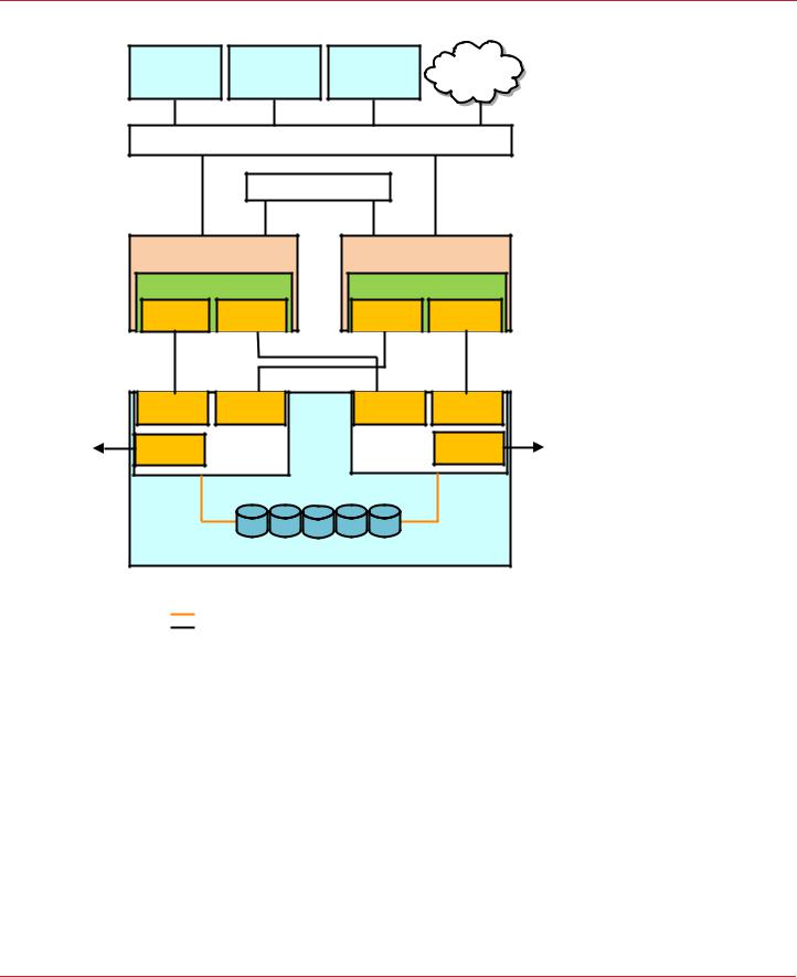
The following figure shows a high-level diagram of a Syncro CS 9286-8e solution connected to a network.
Avago Technologies
- 9 -
Syncro CS 9286-8e Solution User Guide |
Chapter 2: Hardware and Software Setup |
November 2014 |
Syncro CS 9286-8e Two-Server Cluster Hardware Setup |
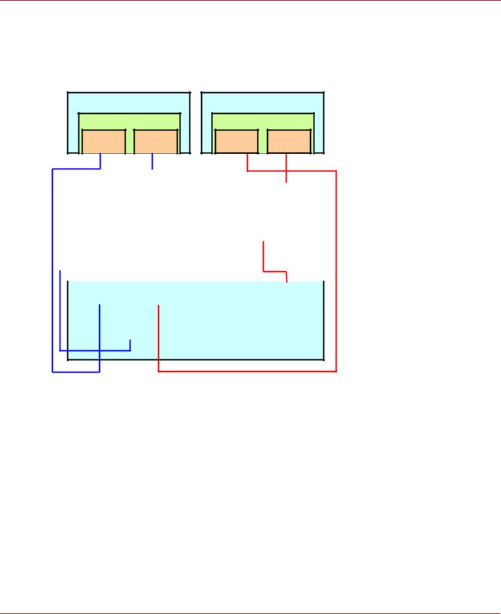
Figure 1 Two-Server Syncro CS 9286-8e Configuration
I3#3) |
I3#3) |
I3#3) |
.ETWORK |
|
#LIENT WITHT |
#LIENT WITHT |
#LIENT WITHT |
||
$.3.3ERVER |
||||
!PPLICATIONS |
!PPLICATIONS |
!PPLICATIONS |
||
|
3XEOLF /RFDO$UHD 1HWZRUN /$1
3ULYDWH /$1
6HUYHU 1RGH$ |
6HUYHU 1RGH % |
&KDVVLV |
&KDVVLV |
3YNCRO #3R E |
3YNCRO #3R E |
||
4OP |
"OTTOM |
4OP |
"OTTOM |
#ONNECTOR |
#ONNECTOR |
#ONNECTOR |
#ONNECTOR |
#ONNECTOR |
|
#ONNECTOR |
|
#ONNECTOR |
|
%XPANDER !
#ONNECTOR |
|
%XPANDER "
#ONNECTOR |
|
#ONNECTOR |
|
([WHUQDO-%2' 6$6 'ULYH (QFORVXUH
.OTE %XPANDER ! CONNECTS!TO 0ORTT! OF THE 3!3 DRIVES |
|
%XPANDER " CONNECTS"TO 0ORTT" OF THE 3!3 DRIVES |
|
3!3!3INGLE ,ANES |
|
3!3!&OURU,ANES |
? |
2.1Syncro CS 9286-8e Two-Server Cluster Hardware Setup
Follow these steps to set up the hardware for a Syncro CS 9286-8e configuration.
1.Unpack the Syncro CS 9286-8e controllers and the CVPM02 modules from the kit, and inspect them for damage.
If any components of the kit appear to be damaged, or if any items are missing from the kit, contact your LSI support representative.
2.Turn off the power to the server units, disconnect the power cords, and disconnect any network cables.
3.Remove the covers from the two server units.
Refer to the server documentation for instructions on how to do this.
4.Review the Syncro CS 9286-8e jumper settings and change them if necessary. Also note the location of the two external Mini-SAS SFF8088 connectors J1A4 and J1B1.
You usually do not need to change the default factory settings of the jumpers. The following figure shows the location of the jumpers and connectors on the controller board.
Avago Technologies
- 10 -
Syncro CS 9286-8e Solution User Guide |
Chapter 2: Hardware and Software Setup |
November 2014 |
Syncro CS 9286-8e Two-Server Cluster Hardware Setup |
The CVFM03 module comes preinstalled on the Syncro CS controller; however, the module is not included in the following figure so that you can see all of the connectors and headers on the controller board. Figure 3 and Figure 4 show the controller with the CVFM03 module installed.
Figure 2 Syncro CS 9286-8e Jumpers and Connectors
J1A1 |
J1A3 |
J2A1 J2A2 |
J2A4 |
|
|
J4A1 |
J4A2 |
J5A1 |
J6A1 |
|||||||||||
|
|
|
|
|
|
|
|
|
|
|
|
|
|
|
|
|
|
|
|
|
|
|
|
|
|
|
|
|
|
|
|
|
|
|
|
|
|
|
|
|
|
|
|
|
|
|
|
|
|
|
|
|
|
|
|
|
|
|
|
|
|
|
|
|
|
|
|
|
|
|
|
|
|
|
|
|
|
|
|
|
|
|
|
|
|
|
|
|
|
|
|
|
|
|
|
|
|
|
|
|
|
|
|
|
|
|
|
|
|
|
|
|
|
|
|
|
|
|
|
|
|
|
|
|
|
Ports
J1A4 0 - 3
J1B1 |
Ports |
J5B1 |
|
4 - 7 |
3_00922-01
J2B1
In the figure, Pin 1 is highlighted in red for each jumper.
The following table describes the jumpers and connectors on the Syncro CS 9286-8e controller.
Table 1 Syncro CS 9286-8e Controller Jumpers
Jumper/ |
Type |
Description |
|
Connector |
|||
|
|
||
|
|
|
|
J1A4 |
External SFF-8088 4-port SAS connector |
In the cabling figures later in this chapter, this connector is called the |
|
|
|
"top" connector. |
|
|
|
|
|
J1B1 |
External SFF-8088 4-port SAS connector |
In the cabling figures later in this chapter, this connector is called the |
|
|
|
"bottom" connector. |
|
|
|
|
|
J1A1 |
Write-Pending LED header |
2-pin connector |
|
|
|
Connects to an LED that indicates when the data in the cache has yet to |
|
|
|
be written to the storage devices. Used when the write-back feature |
|
|
|
is enabled. |
|
|
|
|
|
J1A3 |
Global Drive Fault LED header |
2-pin connector |
|
|
|
Connects to an LED that indicates whether a drive is in a fault condition. |
|
|
|
|
|
J2A1 |
Activity LED header |
2-pin connector |
|
|
|
Connects to an LED that indicates activity on the drives connected to |
|
|
|
the controller. |
|
|
|
|
|
J2A2 |
Advanced Software Options Hardware Key |
3-pin header |
|
|
header |
Enables support for the Advanced Software Options features. |
|
|
|
||
|
|
|
|
J2A4 |
I2O Mode jumper |
2-pin connector |
|
|
|
Installing this jumper causes the RAID controller to run in I2O mode. |
|
|
|
The default, recommended mode of operation is without the shunt and |
|
|
|
running in Fusion mode. |
|
|
|
|
|
J4A1 |
Serial EEPROM |
2-pin connector |
|
|
|
Provides controller information, such as the serial number, revision, and |
|
|
|
manufacturing date. The default is no shunt installed. |
|
|
|
|
Avago Technologies
- 11 -
Syncro CS 9286-8e Solution User Guide |
Chapter 2: Hardware and Software Setup |
November 2014 |
Syncro CS 9286-8e Two-Server Cluster Hardware Setup |
Table 1 Syncro CS 9286-8e Controller Jumpers (Continued)
Jumper/ |
Type |
Description |
|
Connector |
|||
|
|
||
|
|
|
|
J4A2 |
LSI Test header |
Reserved for Avago use. |
|
|
|
|
|
J5A1 |
Serial UART connector for the expander |
Reserved for Avago use. |
|
|
|
|
|
J6A1 |
Serial UART connector for the expander |
Reserved for Avago use. |
|
|
|
|
5.Ground yourself, and then place the Syncro CS controller on a flat, clean, static-free surface.
NOTE |
If you want to replace a bracket, refer to "Replacing Brackets" on |
|
MegaRAID SAS+SATA RAID Controllers Quick Installation Guide |
|
for instructions. |
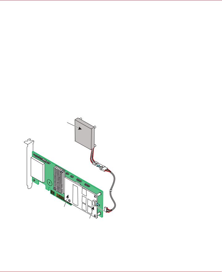
6.Take the cable included with the kit, and insert one end of it into the 9-pin connector on the remote CVPM02 module, as shown in the following figure.
NOTE |
The CVPM02 module is a super-capacitor pack that provides power for |
|
the cache offload capability to protect cached data in case of host |
|
power loss or server failure. |
Figure 3 Connecting the Cable to the Remote CVPM02 Module
CVPM02
Module
3_01853-00
CVFM03
Module
J2A1
7.Mount the CVPM02 module to the inside of the server chassis, as shown in Figure 4. Refer to the server documentation to determine the exact method of mounting the module.
NOTE |
Because server chassis design varies from vendor to vendor, no |
|
standard mounting option exists for the CVPM02 module that is |
|
compatible with all chassis configurations. Authorized resellers and |
|
chassis manufacturers might have recommendations for the location |
Avago Technologies
- 12 -
Syncro CS 9286-8e Solution User Guide |
Chapter 2: Hardware and Software Setup |
November 2014 |
Syncro CS 9286-8e Two-Server Cluster Hardware Setup |
of the power module to provide the most flexibility within various environments.
8.Make sure that the power to the server is still turned off, that the power cords are unplugged, and that the chassis is grounded and has no AC power.
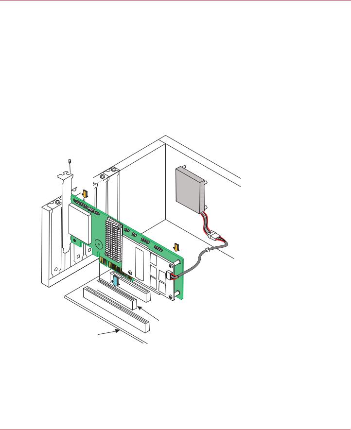
9.Insert the Syncro CS 9286-8e controller into a PCI Express® (PCIe®) slot on the motherboard, as shown in the following figure.
Press down gently, but firmly, to seat the Syncro CS 9286-8e controller correctly in the slot.
NOTE |
The Syncro CS 9286-8e controller is a PCIe x8 card that can operate in |
|
x8 or x16 slots. Some x16 PCIe slots support only PCIe graphics cards; |
|
if you install a Syncro CS 9286-8e in one of these slots, the controller |
|
will not function. Refer to the motherboard documentation for |
|
information about the configuration of the PCIe slots. |
Figure 4 Installing the Syncro CS 9286-8e Controller and Connecting the Cable
Bracket

 Screw
Screw
Press
Here
Press
Here
3_01852-00
PCIe Slot
Edge of
Motherboard
10.Secure the controller to the computer chassis with the bracket screw.
11.Insert the other 9-pin cable connector on the cable into the J2A1 connector on the CVFM03 module, as shown in Figure 3.
12.Repeat step 5 to step 11 to install the second Syncro CS 9286-8e controller in the second server module.
13.Install SAS disk drives in the JBOD enclosure or enclosures.
NOTE |
In a Syncro CS configuration, the expanders in the JBOD enclosure |
|
must have two four-lane IN ports. As an option, the expanders can be |
Avago Technologies
- 13 -

Syncro CS 9286-8e Solution User Guide |
Chapter 2: Hardware and Software Setup |
November 2014 |
Syncro CS 9286-8e Two-Server Cluster Hardware Setup |
configured with a third four-lane port to connect to other cascaded expanders, as shown in Figure 1. JBOD enclosures with dual expanders can support split mode or unified mode. For fault-tolerant cabling configurations, you typically configure the JBOD enclosure in unified mode. (Check with the JBOD enclosure vendor to determine the appropriate settings.)
Refer to the drive documentation to determine any pre-installation configuration requirements. Be sure to use SAS disk drives that are listed on the approved list from LSI. (To view this list, follow the URL listed in Section 1.4, Hardware Compatibility.)
14.If necessary, install network boards in the two server modules and install the cabling between them.
15.Reinstall the covers of the two servers.
16.Install the two server modules and the JBOD enclosure in an industry-standard cabinet, if appropriate, following the manufacturer’s instructions.
17.Use SAS cables to connect the two external connectors on the Syncro CS 9286-8e controller to the JBOD enclosure or enclosures. See Figure 2 to view the location of the external connectors.
See Section 2.2, Cabling Configurations, for specific cabling instructions for one or two JBOD enclosures.
18.Reconnect the power cords and turn on the power to the servers and the JBOD enclosure or enclosures.
Follow the generally accepted best practice by turning on the power on to the JBOD enclosure before you power the two servers. If you power the servers before you power the JBOD enclosure, the servers might not recognize the disk drives.
When the servers boot, a BIOS message appears. The firmware takes several seconds to initialize. The configuration utility prompt times out after several seconds. The second portion of the BIOS message shows the Syncro CS 9286-8e number, firmware version, and cache SDRAM size. The numbering of the controllers follows the PCI slot scanning order used by the host motherboard.
19.Configure the drive groups and the virtual drives on the two controllers.
For specific instructions, see Section 3.1, Creating Virtual Drives on the Controller Nodes. You can use the WebBIOS, StorCLI, or MegaRAID Storage Manager configuration utilities to create the groups and virtual drives.
20.Install the operating system driver on both server nodes.
You must install the software drivers first, before you install the operating system.
You can view the supported operating systems and download the latest drivers for the Syncro CS controllers from the LSI website at http://www.lsi.com/support/Pages/download-search.aspx. Access the download center, and follow the steps to download the appropriate driver.
Refer to the MegaRAID SAS Device Driver Installation User Guide on the Syncro CS Resource CD for more information about installing the driver. Be sure to review the readme file that accompanies the driver.
21.Install the operating system on both server nodes, following the instructions from the operating system vendor. Make sure you apply all of the latest operating system updates and service packs to ensure proper functionality. You have two options for installing the operating system for each controller node:
—Install it on a private volume connected to the system-native storage controller. The recommended best practice is to install the operating system on this private volume because the disks in the clustering configuration cannot see this volume. Therefore, no danger exists of accidentally overwriting the operating system disk when you set up clustering.
—Install it on an exclusive virtual drive connected to the Syncro CS 9286-8e controller. exclusive host access is required for a boot volume so the volume is not overwritten accidentally when you create virtual drives for data storage. For instructions on creating exclusive virtual drives using the WebBIOS utility, see Section 3.1.1, Creating Shared or Exclusive VDs with the WebBIOS Utility.
NOTE |
The Syncro CS 9286-8e solution does not support booting from a |
|
shared operating system volume. |
Avago Technologies
- 14 -
Syncro CS 9286-8e Solution User Guide |
Chapter 2: Hardware and Software Setup |
November 2014 |
Cabling Configurations |
22.Install StorCLI and MegaRAID Storage Manager for the Windows® and Linux operating systems following the installation steps outlined in the StorCLI Reference Manual and MegaRAID SAS Software User Guide on the Syncro CS Resource CD.
2.2Cabling Configurations
This section has information about initially setting up a Syncro CS configuration with one or two JBOD enclosures. It also explains how to add a second JBOD enclosure to an operational single-JBOD configuration without interrupting service on the configuration.
System throughput problems can occur if you use the wrong kind of SAS cables. To minimize the potential for problems, use high-quality cables that meet SAS 2.1 standards and that are less than 6 meters long. See the list of approved cables and vendors on the web link listed at the end of Section 1.4, Hardware Compatibility.
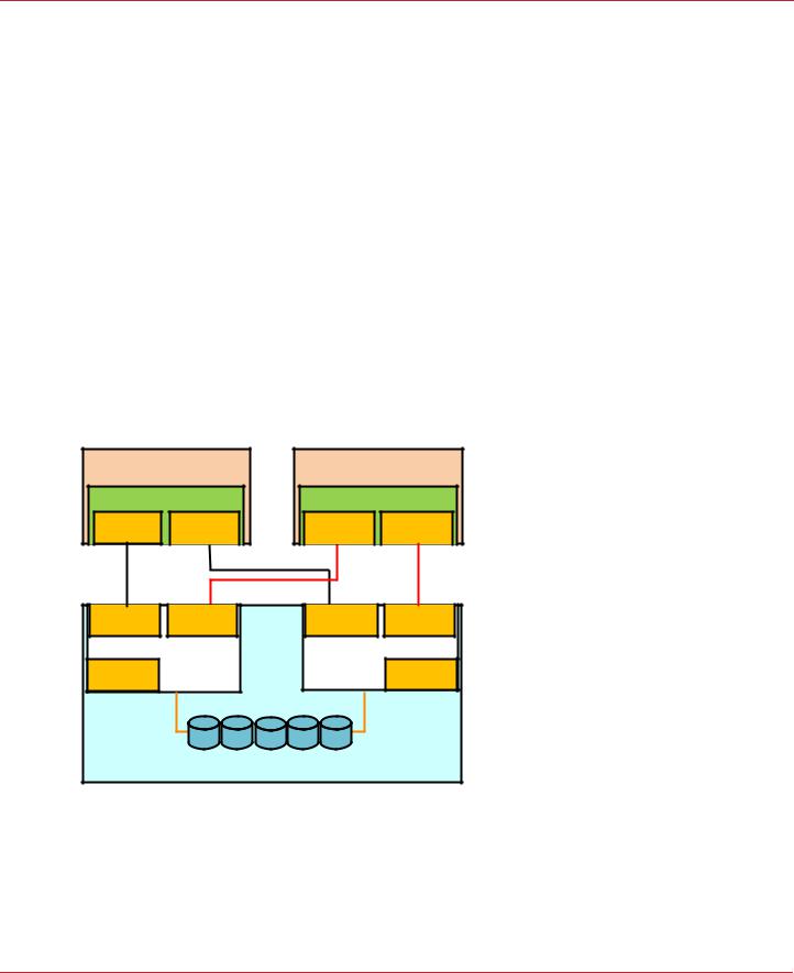
The following figure shows the SAS cable connections for a two-controller-node configuration with a single JBOD enclosure.
NOTE |
In the figures in this section, Top Connector means the external |
|
connector closest to the bracket screw support end of the controller |
|
bracket (connector J1A4 in Figure 2). Bottom Connector means the |
|
other external connector (connector J1B1 in Figure 2). |
Figure 5 Two-Controller-Node Configuration with Single JBOD Enclosure
6HUYHU 1RGH$ |
6HUYHU 1RGH % |
&KDVVLV |
&KDVVLV |
3YNCRO #3R E |
3YNCRO #3R E |
||
4OP |
"OTTOM |
4OP |
"OTTOM |
#ONNECTOR |
#ONNECTOR |
#ONNECTOR |
#ONNECTOR |
#ONNECTOR |
#ONNECTOR |
|
|
#ONNECTOR |
%XPANDER ! |
|
|
||
|
#ONNECTOR |
#ONNECTOR |
|
|
%XPANDER " |
#ONNECTOR |
|
|
||
|
([WHUQDO-%2' 6$6 'ULYH (QFORVXUH
?
The cross-connections between the controllers provide redundant paths that safeguard against expander, cable, or expander failure.
To retain consistent device reporting, the corresponding port numbers for both controllers must be connected to a common enclosure expander. In this example, the top connector on each controllers is connected to Expander A and the bottom connector on each controller is connected to Expander B.
Avago Technologies
- 15 -
Syncro CS 9286-8e Solution User Guide |
Chapter 2: Hardware and Software Setup |
November 2014 |
Cabling Configurations |
The following figure shows the SAS cable connections for a two-controller-node configuration with two JBOD enclosures.
NOTE |
To save space, the figure does not show the disk drives that are in the |
|
JBOD enclosures. |
Figure 6 Two-Controller-Node Configuration with Dual JBOD Enclosures
6HUYHU 1RGH$ |
|
6HUYHU 1RGH % |
|
6\QFUR &6 H |
6\QFUR &6 H |
||
4OP |
"OTTOM |
4OP |
"OTTOM |
#ONNECTOR |
#ONNECTOR |
#ONNECTOR |
#ONNECTOR |
|
|
|
|
|
|
|
|
|
|
|
|
|
|
|
|
|
|
|
#ONNECTORE |
|
#ONNECTORE |
|
#ONNECTOR |
|
|
#ONNECTORE |
|
||||||
|
|
)N |
|
)N |
|
)N |
|
|
)N |
|
||||||
|
|
|
([SDQGHU$ |
|
|
([SDQGHU % |
|
|||||||||
|
|
|
|
#ONNECTORE |
|
|
|
#ONNECTOR |
|
|
||||||
|
|
|
|
|
/UT |
|
|
|
/UT |
|
|
|||||
|
|
|
|
|
|
|
|
|
|
|
|
|
|
|
|
|
|
|
|
|
|
|
|
|
'ULYH (QFORVXUH$ |
|
|
|
|||||
|
|
|
|
|
|
|
|
|
|
|
|
|
||||
|
|
|
|
|
|
|
|
|
|
|
|
|
|
|
|
|
|
|
#ONNECTORE |
|
#ONNECTORE |
|
#ONNECTORE |
|
|
#ONNECTORE |
|
||||||
|
|
)N |
|
)N |
|
)N |
|
|
)N |
|
||||||
|
|
|
|
|
|
|
|
|
|
|
|
|
|
|||
|
|
|
([SDQGHU$ |
|
|
([SDQGHU % |
|
|||||||||
|
|
|
|
#ONNECTOR |
|
|
|
#ONNECTOR |
|
|
||||||
|
|
|
|
/UT |
|
|
|
/UT |
|
|
|
|||||
|
|
|
|
|
|
|
|
|
|
|
|
|
|
|
|
|
'ULYH (QFORVXUH %
?
The recommended method shown in the preceding figure is preferable to simply daisy-chaining a second JBOD enclosure from the single-JBOD configuration shown in Figure 5, because a single power failure in the first JBOD enclosure could interrupt all data access. Instead, connect the second Syncro CS controller envisioning the JBOD enclosures in reverse order. The resulting top-down/bottom-up cabling approach shown in the preceding figure is preferred because it assures continued access to operating drives if either of the JBOD enclosures fails or is removed.
The following figure shows how to hot-add a second JBOD enclosure to an existing two-server cluster without interrupting service on the HA configuration.
NOTE |
To save space, the figure does not show the disk drives that are in the |
|
JBOD enclosures. |
Avago Technologies
- 16 -

Syncro CS 9286-8e Solution User Guide |
Chapter 2: Hardware and Software Setup |
November 2014 |
Cabling Configurations |
Figure 7 Adding a Second JBOD Enclosure – Redundant Configuration
6HUYHU 1RGH$ |
|
6HUYHU 1RGH % |
|
6\QFUR &6 H |
6\QFUR &6 H |
||
4OP |
"OTTOM |
4OP |
"OTTOM |
#ONNECTOR |
#ONNECTOR |
#ONNECTOR |
#ONNECTOR |
|
|
|
|
|
|
|
|
|
|
|
|
|
|
|
|
#ONNECTOR |
|
#ONNECTOR |
|
#ONNECTOR |
|
#ONNECTOR |
|
||||||
|
)N |
|
)N |
|
)N |
|
)N |
|
||||||
|
([SDQGHU$ |
|
|
|
([SDQGHU % |
|
||||||||
|
|
#ONNECTOR |
|
|
|
|
#ONNECTOR |
|
|
|||||
|
|
|
/UT |
|
|
|
|
/UT |
|
|
||||
|
|
|
|
|
|
|
|
|
|
|
|
|
|
|
|
|
|
|
|
|
|
'ULYH (QFORVXUH$ |
|
|
|
|
|||
|
|
|
|
|
|
|
|
|
|
|
|
|
||
|
|
|
|
|
|
|
|
|
|
|
|
|
|
|
|
|
#ONNECTOR |
|
|
#ONNECTOR |
|
#ONNECTOR |
|
#ONNECTOR |
|
||||
|
|
)N |
|
|
)N |
|
)N |
|
)N |
|
||||
|
|
|
|
|
|
|
|
|
|
|
|
|||
|
|
|
([SDQGHU$ |
|
|
([SDQGHU % |
|
|||||||
|
|
|
#ONNECTOR |
|
|
|
#ONNECTOR |
|
|
|||||
|
|
|
|
/UT |
|
|
|
/UT |
|
|
||||
|
|
|
|
|
|
|
|
|
|
|
|
|
|
|
'ULYH (QFORVXUH %
|
|
?
The steps for adding the second JBOD enclosure are as follows:
1.Connect a link from connector 2 on Expander B of JBOD enclosure A to connector 1 on expander B of JBOD enclosure B.
2.Disconnect the link from connector 1 on expander A of JBOD enclosure A and reconnect it to connector 1 on expander A of JBOD enclosure B.
3.Disconnect the link from connector 0 on expander A of JBOD enclosure A and reconnect it to connector 0 on expander A of JBOD enclosure B.
4.Connect the link from connector 2 on expander A of JBOD enclosure B to connector 0 on expander A of JBOD enclosure A.
Avago Technologies
- 17 -

Syncro CS 9286-8e Solution User Guide |
Chapter 3: Creating the Cluster |
November 2014 |
Creating Virtual Drives on the Controller Nodes |
Chapter 3: Creating the Cluster
This chapter explains how to set up HA-DAS clustering on a Syncro CS 9286-8e configuration after the hardware is fully configured and the operating system is installed.
3.1Creating Virtual Drives on the Controller Nodes
This section describes that next step in setup, which is creating VDs on the controller nodes.
The HA-DAS cluster configuration requires a minimum of one shared VD to be used as a quorum disk to enable the operating system support for clusters. Refer to the MegaRAID SAS Software User Guide for information about the available RAID levels and the advantages of each one.
As explained in the instructions in the following sections, VDs created for storage in an HA-DAS configuration must be shared. If you do not designate them as shared, the VDs are visible only from the controller node from which they were created.
You can use the WebBIOS pre-boot utility to create the VDs. You can also use the LSI MegaRAID Storage Manager (MSM) utility or the StorCLI utility to create VDs after the OS has booted. Refer to the MegaRAID SAS Software User Guide for complete instructions on using these utilities.
3.1.1Creating Shared or Exclusive VDs with the WebBIOS Utility
To coordinate the configuration of the two controller nodes, both nodes must be booted into the WebBIOS pre-boot utility. The two nodes in the cluster system boot simultaneously after power on, so you must rapidly access both consoles. One of the systems is used to create the VDs; the other system simply remains in the pre-boot utility. This approach keeps the second system in a state that does not fail over while the VDs are being created on the
first system.
NOTE |
The WebBIOS utility cannot see boot sectors on the disks. Therefore, |
|
be careful not to select the boot disk for a VD. Preferably, unshare the |
|
boot disk before doing any configuration with the pre-boot utility. To |
|
do this, select Logical Drive Properties and deselect the Shared |
|
Virtual Disk property. |
Follow these steps to create VDs with the WebBIOS utility.
1.When prompted during the POST on the two systems, use the keyboard to access the WebBIOS pre-boot BIOS utility (on both systems) by pressing Ctrl-H.
Respond quickly, because the system boot times are very similar and the time-out period is short. When both controller nodes are running the WebBIOS utility, follow these steps to create RAID 5 arrays.
NOTE |
To create a RAID 0, RAID 1, or RAID 6 array, modify the instructions to |
|
select the appropriate number of disks. |
2.Click Start.
3.On the WebBIOS main page, click Configuration Wizard, as shown in the following figure.
Avago Technologies
- 18 -

Syncro CS 9286-8e Solution User Guide |
Chapter 3: Creating the Cluster |
November 2014 |
Creating Virtual Drives on the Controller Nodes |
Figure 8 WebBIOS Main Page
The first Configuration Wizard window appears.
4.Select Add Configuration and click Next.
5.On the next wizard screen, select Manual Configuration and click Next. The Drive Group Definition window appears.
6.In the Drives panel on the left, select the first drive, then hold down the Ctrl key and select more drives for the array, as shown in the following figure.
Figure 9 Selecting Drives
7.Click Add To Array, click ACCEPT, and click Next.
Avago Technologies
- 19 -
Syncro CS 9286-8e Solution User Guide |
Chapter 3: Creating the Cluster |
November 2014 |
Creating Virtual Drives on the Controller Nodes |
8.On the next screen, click Add to SPAN, and then click Next.
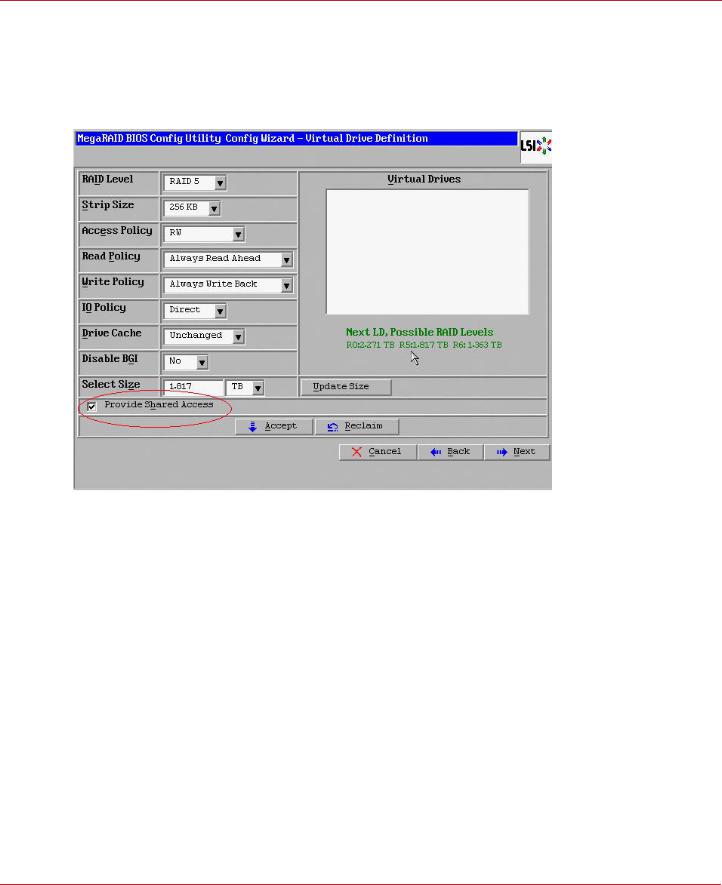
9.On the next screen, click Update Size.
10.Select Provide Shared Access on the bottom left of the window, as shown in the following figure. Alternatively, deselect this option to create an exclusive VD as a boot volume for this cluster node.
Figure 10 Virtual Drive Definition
The Provide Shared Access option enables a shared VD that both controller nodes can access. If you uncheck this box, the VD has a status of exclusive, and only the controller node that created this VD can access it.
11.On this same page, click Accept, and then click Next.
12.On the next page, click Next.
13.Click Yes to accept the configuration.
14.Repeat the previous steps to create the other VDs.
As the VDs are configured on the first controller node, the other controller node’s drive listing is updated to reflect the use of the drives.
15.When prompted, click Yes to save the configuration, and click Yes to confirm that you want to initialize it.
16.Define hot spare disks for the VDs to maximize the level of data protection.
NOTE |
The Syncro CS 9286-8e solution supports global hot spares and |
|
dedicated hot spares. Global hot spares are global for the cluster, not |
|
for a controller. |
17. When all VDs are configured, reboot both systems as a cluster.
Avago Technologies
- 20 -
Syncro CS 9286-8e Solution User Guide |
Chapter 3: Creating the Cluster |
November 2014 |
Creating Virtual Drives on the Controller Nodes |
3.1.2Creating Shared or Exclusive VDs with StorCLI
The Storage Command Line Tool, StorCLI, is the command-line management utility for MegaRAID, that you can use to create and manage VDs. StorCLI can run in any directory on the server. The following procedure assumes that a current copy of the 64-bit version of StorCLI is located on the server in a common directory as the StorCLI executable and the commands are run with administrator privileges.
1. At the command prompt, run the following command: storcli /c0/vall show
The c0 parameter presumes that there is only one Syncro CS 9286-8e controller in the system or that these steps reference the first Syncro CS 9286-8e controller in a system with multiple controllers.
The following figure shows some sample configuration information that appears in response to the command.
Figure 11 Sample Configuration Information
The command generates many lines of information that scroll down in the window. You must use some of this information to create the shared VD.
2.Find the Device ID for the JBOD enclosure for the system and the Device IDs of the available physical drives for the VD that you will create.
In the second table in the preceding figure, the enclosure device ID of 252 appears under the heading EID, and the device ID of 0 appears under the heading DID. Use the scroll bar to find the device IDs for the other physical drives for the VD.
Detailed drive information, such as the drive group, capacity, and sector size, follows the device ID in the table and is explained in the text below the table.
3.Create the shared VD using the enclosure and drive device IDs with the following command line syntax:
Storcli /c0 add vd rX drives=e:s
The HA-DAS version of StorCLI creates, by default, a shared VD that is visible to all cluster nodes.
Avago Technologies
- 21 -

Syncro CS 9286-8e Solution User Guide |
Chapter 3: Creating the Cluster |
November 2014 |
Creating Virtual Drives on the Controller Nodes |
The following notes explain the command line parameters.
—The /c0 parameter selects the first Syncro CS 9286-8e controller in the system.
—The add vd parameter configures and adds a VD (logical disk).
—The rX parameter selects the RAID level, where X is the level.
—The opening and closing square brackets define the list of drives for the VD. Each drive is listed in the form enclosure device ID: [slot]drive device ID.
NOTE |
To create a VD that is visible only to the node that created it (such as |
|
creating a boot volume for this cluster node), add the |
|
[ExclusiveAccess] parameter to the command line. |
For more information about StorCLI command line parameters, refer to the MegaRAID SAS Software User Guide.
3.1.3Creating Shared or Exclusive VDs with MegaRAID Storage Manager
Follow these steps to create VDs for data storage with MegaRAID Storage Manager. When you create the VDs, you assign the Share Virtual Drive property to them to make them visible from both controller nodes. This example assumes you are creating a RAID 5 redundant VD. Modify the instructions as needed for other RAID levels.
NOTE |
Not all versions of MegaRAID Storage Manager support HA-DAS. |
|
Check the release notes to determine if your version of MegaRAID |
|
Storage Manager supports HA-DAS. Also, see Section 5.1, Verifying |
|
HA-DAS Support in Tools and the OS Driver. |
1.In the left panel of the MegaRAID Storage Manager Logical pane, right-click the Syncro CS 9286-8e controller and select Create Virtual Drive from the pop-up menu.
The Create Virtual Drive wizard appears.
2.Select the Advanced option and click Next.
3.In the next wizard screen, select RAID 5 as the RAID level, and select unconfigured drives for the VD, as shown in the following figure.
Figure 12 Drive Group Settings
Avago Technologies
- 22 -
Syncro CS 9286-8e Solution User Guide |
Chapter 3: Creating the Cluster |
November 2014 |
Creating Virtual Drives on the Controller Nodes |
4.Click Add to add the VD to the drive group.
The selected drives appear in the Drive groups window on the right.
5.Click Create Drive Group. Then click Next to continue to the next window. The Virtual Drive Settings window appears.
6.Enter a name for the VD.
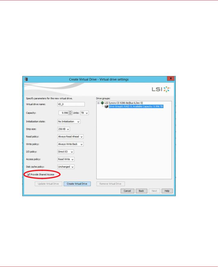
7.Select Always Write Back as the Write policy option, and select other VD settings as required.
8.Select the Provide Shared Access option, as shown in the following figure.
NOTE |
If you do not select Provide Shared Access, the VD is visible only from |
|
the server node on which it is created. Leave this option unselected if |
|
you are creating a boot volume for this cluster node. |
Figure 13 Provide Shared Access Option
9.Click Create Virtual Drive to create the virtual drive with the settings you specified. The new VD appears in the Drive groups window on the right of the window.
10.Click Next to continue.
The Create Virtual Drive Summary window appears, as shown in the following figure.
Avago Technologies
- 23 -

Syncro CS 9286-8e Solution User Guide |
Chapter 3: Creating the Cluster |
November 2014 |
HA-DAS CacheCade Support |
Figure 14 Create Virtual Drive Summary
11.Click Finish to complete the VD creation process.
12.Click OK when the Create Virtual Drive - complete message appears.
3.1.3.1Unsupported Drives
Drives that are used in the Syncro CS 9286-8e solution must selected from the list of approved drives listed on the LSI website (see the URL in Section 1.4, Hardware Compatibility). If the MegaRAID Storage Manager (MSM) utility finds a drive that does not meet this requirement, it marks the drive as Unsupported, as shown in the following figure.
Figure 15 Unsupported Drive in MegaRAID Storage Manager
3.2HA-DAS CacheCade Support
The Syncro CS 9286-8e controller includes support for CacheCade 1.0, a feature that uses SAS SSD devices for read caching of frequently accessed read data. When a VD is enabled for the CacheCade feature, frequently read data regions of the VD are copied into the SSD when the CacheCade algorithm determines the region is a good candidate. When the data region is in the CacheCade SSD volume, the firmware can service related reads from the faster-access SSD volume instead of the higher-latency VD. The CacheCade feature uses a single SSD to service multiple VDs.
Avago Technologies
- 24 -
Loading...