

Page 1

Syncro® CS 9361-8i and Syncro CS 9380-8e
Controllers
User Guide
Version 2.0
November 2014
55410-00, Rev. B
Page 2

Syncro CS 9361-8i and Syncro CS 9380-8e Controllers User Guide
November 2014
For a comprehensive list of changes to this document, see the Revision History.
Corporate Headquarters Email Website
San Jose, CA globalsupport.pdl@avagotech.com www.lsi.com
Avago, Avago Technologies, the A logo, LSI, and Storage by LSI, CacheCade, CacheVault, MegaRAID, MegaRAID
Storage Manager, SafeStore, and Syncro are trademarks of Avago Technologies in the United States and other
countries. All other brand and product names may be trademarks of their respective companies.
Data subject to change. Copyright © 2014 Avago Technologies. All Rights Reserved.
Page 3

Syncro CS 9361-8i and Syncro CS 9380-8e Controllers User Guide
November 2014
Table of Contents
Table of Contents
Chapter 1: Introduction . . . . . . . . . . . . . . . . . . . . . . . . . . . . . . . . . . . . . . . . . . . . . . . . . . . . . . . . . . . . . . . . . . . . . . . . . . . . . . . . . . . . . . . . . . . . . . . . . . . . . . . . . 4
1.1 Concepts of High-Availability DAS . . . . . . . . . . . . . . . . . . . . . . . . . . . . . . . . . . . . . . . . . . . . . . . . . . . . . . . . . . . . . . . . . . . . . . . . . . . . . . . . . . . . . . . . . . . . . . . . . . . 4
1.2 HA-DAS Terminology . . . . . . . . . . . . . . . . . . . . . . . . . . . . . . . . . . . . . . . . . . . . . . . . . . . . . . . . . . . . . . . . . . . . . . . . . . . . . . . . . . . . . . . . . . . . . . . . . . . . . . . . . . . . . . . 5
1.3 Syncro CS 9361-8i and Syncro CS 9380-8e Solution Features . . . . . . . . . . . . . . . . . . . . . . . . . . . . . . . . . . . . . . . . . . . . . . . . . . . . . . . . . . . . . . . . . . . . . . . . . 5
1.4 Hardware Compatibility . . . . . . . . . . . . . . . . . . . . . . . . . . . . . . . . . . . . . . . . . . . . . . . . . . . . . . . . . . . . . . . . . . . . . . . . . . . . . . . . . . . . . . . . . . . . . . . . . . . . . . . . . . . . . 6
1.5 Overview of the Hardware Installation, Cluster Setup, and Configuration . . . . . . . . . . . . . . . . . . . . . . . . . . . . . . . . . . . . . . . . . . . . . . . . . . . . . . . . . . . . . 7
1.6 Performance Considerations . . . . . . . . . . . . . . . . . . . . . . . . . . . . . . . . . . . . . . . . . . . . . . . . . . . . . . . . . . . . . . . . . . . . . . . . . . . . . . . . . . . . . . . . . . . . . . . . . . . . . . . . 7
Chapter 2: Hardware and Software Setup . . . . . . . . . . . . . . . . . . . . . . . . . . . . . . . . . . . . . . . . . . . . . . . . . . . . . . . . . . . . . . . . . . . . . . . . . . . . . . . . . . . . . . . . 9
2.1 Syncro CS 9361-8i Controller Kit . . . . . . . . . . . . . . . . . . . . . . . . . . . . . . . . . . . . . . . . . . . . . . . . . . . . . . . . . . . . . . . . . . . . . . . . . . . . . . . . . . . . . . . . . . . . . . . . . . . . . 9
2.2 Syncro CS 9361-8i Cluster-in-a-Box Hardware Setup . . . . . . . . . . . . . . . . . . . . . . . . . . . . . . . . . . . . . . . . . . . . . . . . . . . . . . . . . . . . . . . . . . . . . . . . . . . . . . . . 10
2.3 Syncro CS 9380-8e Controller Kit . . . . . . . . . . . . . . . . . . . . . . . . . . . . . . . . . . . . . . . . . . . . . . . . . . . . . . . . . . . . . . . . . . . . . . . . . . . . . . . . . . . . . . . . . . . . . . . . . . . 19
2.4 Syncro CS 9380-8e Two-Server Cluster Hardware Setup . . . . . . . . . . . . . . . . . . . . . . . . . . . . . . . . . . . . . . . . . . . . . . . . . . . . . . . . . . . . . . . . . . . . . . . . . . . . . 21
2.5 Syncro CS Cluster-in-a-Box Software Setup . . . . . . . . . . . . . . . . . . . . . . . . . . . . . . . . . . . . . . . . . . . . . . . . . . . . . . . . . . . . . . . . . . . . . . . . . . . . . . . . . . . . . . . . . 29
Revision History . . . . . . . . . . . . . . . . . . . . . . . . . . . . . . . . . . . . . . . . . . . . . . . . . . . . . . . . . . . . . . . . . . . . . . . . . . . . . . . . . . . . . . . . . . . . . . . . . . . . . . . . . . . . . . . 30
Avago Technologies
- 3 -
Page 4

Syncro CS 9361-8i and Syncro CS 9380-8e Controllers User Guide
November 2014
Chapter 1: Introduction
This document explains how to set up and configure the hardware and the software for the Syncro® CS 9361-8i and
the Syncro 9380-8e high-availability direct-attached storage (HA-DAS) solution.
The Syncro CS solution provides fault tolerance capabilities as a key part of a high-availability data storage system.
This solution combines redundant servers, LSI® HA-DAS RAID controllers, computer nodes, cable connections,
common SAS enclosures, and dual-ported SAS storage devices.
The redundant components and software technologies provide a high-availability system with ongoing service that is
not interrupted by the following events:
The failure of a single internal node does not interrupt service because the solution has multiple nodes with
cluster failover.
An expander failure does not interrupt service because the dual expanders in every enclosure provide redundant
data paths.
A drive failure does not interrupt service because RAID fault tolerance is part of the configuration.
A system storage expansion or maintenance activity can be completed without requiring an interruption of
service because of redundant components, management software, and maintenance procedures.
Concepts of High-Availability DAS
Chapter 1: Introduction
1.1 Concepts of High-Availability DAS
In terms of data storage and processing, High Availability (HA) means a computer system design that ensures a high
level of operational continuity and data access reliability over a long period of time. High-availability systems are
critical to the success and business needs of small and medium-sized business (SMB) customers, such as retail outlets
and health care offices, who cannot afford to have their computer systems go down. An HA-DAS solution enables
customers to maintain continuous access to and use of their computer system. Shared direct-attached drives are
accessible to multiple servers, thereby maintaining ease of use and reducing storage costs.
A cluster is a group of computers working together to run a common set of applications and to present a single logical
system to the client and application. Failover clustering provides redundancy to the cluster group to maximize up-time
by utilizing fault-tolerant components. In the example of two servers with shared storage that comprise a failover
cluster, when a server fails, the failover cluster automatically moves control of the shared resources to the surviving
server with no interruption of processing. This configuration allows seamless failover capabilities in the event of
planned failover (maintenance mode) for maintenance or upgrade, or in the event of a failure of the CPU, memory, or
other server failures.
The Syncro CS solution is specifically designed to provide HA-DAS capabilities for a class of server chassis that include
two server motherboards in one chassis. This chassis architecture is often called a cluster in a box (CiB).
Because multiple initiators exist in a clustered pair of servers (nodes) with a common shared storage domain, there is a
concept of device reservations in which physical drives, drive groups, and virtual drives (VDs) are managed by a
selected single initiator. For HA-DAS, I/O transactions and RAID management operations are normally processed by a
single Syncro CS controller, and the associated physical drives, drive groups, and VDs are only visible to that controller.
To assure continued operation, all other physical drives, drive groups, and VDs are also visible to, though not normally
controlled by, the Syncro CS controller. This key functionality allows the Syncro CS solution to share VDs among
multiple initiators as well as exclusively constrain VD access to a particular initiator without the need for SAS zoning.
Node downtime in an HA system can be either planned and unplanned. Planned node downtime is the result of
management-initiated events, such as upgrades and maintenance. Unplanned node downtime results from events
that are not within the direct control of IT administrators, such as failed software, drivers, or hardware. The Syncro CS
9361-8i solution protects your data and maintains system up-time from both planned and unplanned node
downtime. It also enables you to schedule node downtime to update hardware or firmware, and so on. When you
Avago Technologies
- 4 -
Page 5

Syncro CS 9361-8i and Syncro CS 9380-8e Controllers User Guide
November 2014
bring one controller node down for scheduled maintenance, the other node takes over with no interruption
of service.
1.2 HA-DAS Terminology
This section defines some additional important HA-DAS terms.
Cache Mirror: A cache coherency term describing the duplication of write-back cached data across two
controllers.
Exclusive Access: A host access policy in which a VD is only exposed to, and accessed by, a single specified server.
Failover: The process in which the management of drive groups and VDs transitions from one controller to the
peer controller to maintain data access and availability.
HA Domain: A type of storage domain that consists of a set of HA controllers, cables, shared disk resources, and
storage media.
Peer Controller: A relative term to describe the HA controller in the HA domain that acts as the failover controller.
Server/Controller Node: A processing entity composed of a single host processor unit or multiple host processor
units that is characterized by having a single instance of a host operating system.
Server Storage Cluster: An HA storage topology in which a common pool of storage devices is shared by two
computer nodes through dedicated Syncro CS controllers.
Shared Access: A host access policy in which a VD is exposed to, and can be accessed by, all servers in the HA
domain.
Virtual Drive (VD): A storage unit created by a RAID controller from one or more physical drives. Although a
virtual drive can consist of multiple drives, it is seen by the operating system as a single drive. Depending on the
RAID level used, the virtual drive might retain redundant data in case of a drive failure.
Chapter 1: Introduction
HA-DAS Terminology
1.3 Syncro CS 9361-8i and Syncro CS 9380-8e Solution Features
The Syncro CS solution for these controllers supports the following HA features.
Server storage cluster topology, enabled by the following supported operating systems:
— Microsoft® Windows Server®2008 R2
— Microsoft Windows Server 2008 R2 SP1
— Microsoft Windows Server 2012
— Microsoft Windows Server 2012 R2
— Microsoft Windows Storage Server 2012
— Microsoft Windows Storage Server 2012 R2
— Red Hat® Enterprise Linux 6.3
— Red Hat Enterprise Linux 6.4
— CentOS® 6.5
— SuSE® Linux Enterprise Server 11 SP3
— SuSE Linux Enterprise Server 11 SP2
Clustering/HA services support:
— Microsoft failover clustering
— Red Hat High Availability Add-on
— SuSE High Availability Extensions
Dual-active HA with shared storage
Avago Technologies
- 5 -
Page 6

Syncro CS 9361-8i and Syncro CS 9380-8e Controllers User Guide
November 2014
Controller-to-controller intercommunication over SAS
Write-back cache coherency
Shared and exclusive VD I/O access policies
Operating system boot from the controller (exclusive access)
Controller hardware and property mismatch detection, handling, and reporting
Global hot spare support for all volumes in the HA domain
Planned and unplanned failover modes
CacheVault® modules to provide cache cached data protection in case of host power loss or server failure
Full MegaRAID® features, with the following exceptions.
— CacheCade® is not supported.
— Dimmer switch is not supported.
— SGPIO sideband signaling for enclosure management is not supported.
— SATA drives are not supported.
— SSD drives that do not support SCSI-3 persistent reservations (PR) for the VDs are not supported.
— System/JBOD physical drives are not supported (that is, the individual physical drives are not exposed to the
operating system).
— Drives that are directly attached to the controller (not through an expander device) are not supported.
— Cluster-active reconstruction operations (RAID-Level Migration or Online Capacity Expansion) are not
supported.
— Patrol Read operations that were in progress do not resume after failover.
— Firmware-level node incompatibility details are not reported for non-premium features.
— The Maintain Pd Fail History feature is not supported. This feature, which is available in the WebBIOS utility
and the MegaRAID Command Tool, maintains the history of all drive failures.
— Cache memory recovery is not supported for I/O shipped commands. I/O shipping occurs when a cluster
node has a problem in the I/O path, and the I/O from that cluster node is shipped to the other cluster node.
— Battery backup units are not supported.
— HA-DAS does not support configuration of a global hot spare (GHS) when no VDs exist on the two nodes.
Configuring a GHS when no VDs exist on the two nodes and then rebooting both nodes can cause problems.
Chapter 1: Introduction
Hardware Compatibility
1.4 Hardware Compatibility
The servers, disk drives, and optional enclosures you use in the Syncro CS solution must be selected from the list of
approved components that LSI has tested for compatibility. Refer to the web page for the compatibility lists at
http://www.lsi.com/channel/support/pages/interoperability.aspx.
NOTE The Syncro CS solution requires the use of SAS SSD drives that support
SCSI-3 persistent reservations (PR) for the VDs. The compatibility list
shows the SAS SSD drives that meet the HA-DAS requirements.
Avago Technologies
- 6 -
Page 7

Syncro CS 9361-8i and Syncro CS 9380-8e Controllers User Guide
November 2014
Overview of the Hardware Installation, Cluster Setup, and Configuration
Chapter 1: Introduction
1.5 Overview of the Hardware Installation, Cluster Setup, and Configuration
Chapters 2 describes how to install the hardware and software so that you can use the fault tolerance capabilities of
HA-DAS to provide continuous service in event of drive failure or server failure and expand the system storage
Chapter 2 documents how to connect the CacheVault modules, and then install the Syncro CS controllers and the
remote mount boards in the CiB enclosure. In addition, it lists the steps required after controller installation and cable
connection, which include the following:
Configure the drive groups and the virtual drives on the two controllers
Install the operating system driver on both server nodes
Install the operating system on both server nodes, following the instructions from the manufacturer
Install StorCLI and MegaRAID Storage Manager™ utilities
Refer to the 12Gb/s MegaRAID SAS Software User Guide at http://www.lsi.com/downloads/ for information about
running the configuration utilities.
Refer to the Syncro CS 9361-8i and Syncro CS 9380-8e Solution User Guide at http://www.lsi.com/downloads/ for the
procedures used to perform the following actions after the hardware is fully configured and the operating system is
installed:
Install and enable the Cluster feature on both servers.
Set up a cluster under the supported operating systems
Configure drive groups and virtual drives
1.6 Performance Considerations
SAS technology offers throughput-intensive data transfers and low latency times. Throughput is crucial during
failover periods where the system needs to process reconfiguration activity in a fast, efficient manner. SAS offers a
throughput rate of 12 Gb/s over a single lane. SAS controllers and enclosures typically aggregate 4 lanes into an x4
wide link, giving an available bandwidth of 48 Gb/s across a single connector, which makes SAS ideal for HA
environments.
Syncro CS controllers work together across a shared SAS link to achieve sharing, cache coherency, heartbeat
monitoring and redundancy by using a set of protocols to carry out these functions. At any point in time, a particular
VD is accessed or owned by a single controller. This owned VD is a termed a local VD. The second controller is aware of
the VD on the first controller, but it has only indirect access to the VD. The VD is a remote VD for the second controller.
In a configuration with multiple VDs, the workload is typically balanced across controllers to provide a higher degree
of efficiency.
When a controller requires access to a remote VD, the I/Os are shipped to the remote controller, which processes the
I/O locally. I/O requests that are handled by local VDs are much faster than those handled by remote VDs.
The preferred configuration is for the controller to own the VD that hosts the clustered resource (the MegaRAID
Storage Manager utility shows which controller owns this VD). If the controller does not own this VD, it must issue a
request to the peer controller to ship the data to it, which affects performance. This situation can occur if the
configuration has been configured incorrectly or if the system is in a failover situation.
NOTE Performance tip: You can reduce the impact of I/O shipping by
locating the VD or drive groups with the server node that is primarily
driving the I/O load. Avoid drive group configurations with multiple
VDs whose I/O load is split between the server nodes.
Avago Technologies
- 7 -
Page 8

Syncro CS 9361-8i and Syncro CS 9380-8e Controllers User Guide
November 2014
MSM has no visibility to remote VDs, so all VD management operations must be performed locally. A controller that
has no direct access to a VD must use I/O shipping to access the data if it receives a client data request. Accessing the
remote VD affects performance because of the I/O shipping overhead.
NOTE Performance tip: Use the MSM utility to verify correct resource
ownership and load balancing. Load balancing is a method of
spreading work between two or more computers, network links, CPUs,
drives, or other resources. Load balancing is used to maximize
resource use, throughput, or response time. Load balancing is the key
to ensuring that client requests are handled in a timely,
efficient manner.
Chapter 1: Introduction
Performance Considerations
Avago Technologies
- 8 -
Page 9

Syncro CS 9361-8i and Syncro CS 9380-8e Controllers User Guide
November 2014
Chapter 2: Hardware and Software Setup
This chapter explains how to set up the hardware and software for the Syncro CS 9361-8i solution and the Syncro CS
9380-8e solution with two controller nodes and shared storage. For this implementation, use a Cluster-in-a-Box (CiB)
configuration in which the two server nodes with Syncro CS controllers and the shared disk drives are installed and
connected inside a single CiB enclosure.
The Syncro CS cluster-in-a-box (CiB) system design combines two servers and a common pool of direct attached
drives within one custom-designed enclosure. After you initially set it up, the CiB system design simplifies the
deployment of two-node clusters because all components and connections are contained in one closed unit.
The Syncro CS cluster-in-a-box configuration requires a specially designed server and storage chassis that includes
two Syncro CS controller boards and multiple SAS drives selected from the LSI disk compatibility list (see the URL in
Section 1.4, Hardware Compatibility).
2.1 Syncro CS 9361-8i Controller Kit
The LSI Syncro CS 9361-8i controller kit includes the following items:
— Two Syncro CS 9361-8i controllers
— Two CacheVault Flash Modules 04 (CVFM04) (pre-installed on the controllers)
— Two CacheVault Power Modules 02 (CVPM02)
— Two CacheVault Power Module mounting clips and hardware
— Two CacheVault Power Module extension cables
— Two low-profile brackets
— Syncro CS 9361-8i and Syncro CS 9380-8e Controllers Getting Started Guide
Chapter 2: Hardware and Software Setup
Syncro CS 9361-8i Controller Kit
The Syncro CS 9361-8i controllers in the kit include the CacheVault Module Kit LSICVM02, which consists of a
CacheVault Flash Module 04 (CVFM04), a CacheVault Power Module 02 (CVPM02), a clip, and a cable.
The CVFM04 module is an Open NAND Flash Interface (ONFI) flash module that is pre-installed on the Syncro CS
controller. The CVFM04 module provides cache off-load capability to protect cached data in case of host power loss or
server failure.
The CVPM02 module is a super-capacitor pack that provides power for the backup of your data in case of host power
loss or server failure. The CVPM02 module provides both capacitor charge maintenance and capacitor health
monitoring functions similar to those of an intelligent battery backup unit.
If a power failure occurs, the CVPM02 module unit provides power to transfer the cache memory contents from DRAM
to a nonvolatile flash memory array on the CVFM04 module the next time the controller is power on. Cached data can
then be written to the storage devices.
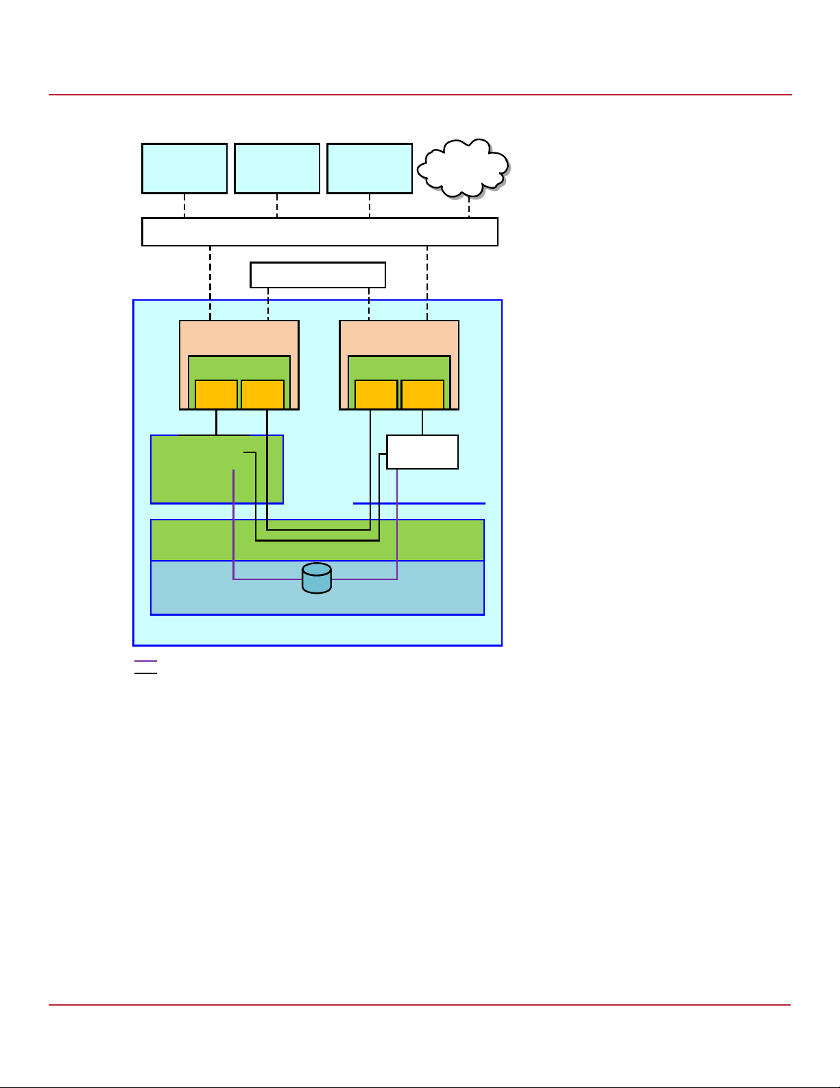
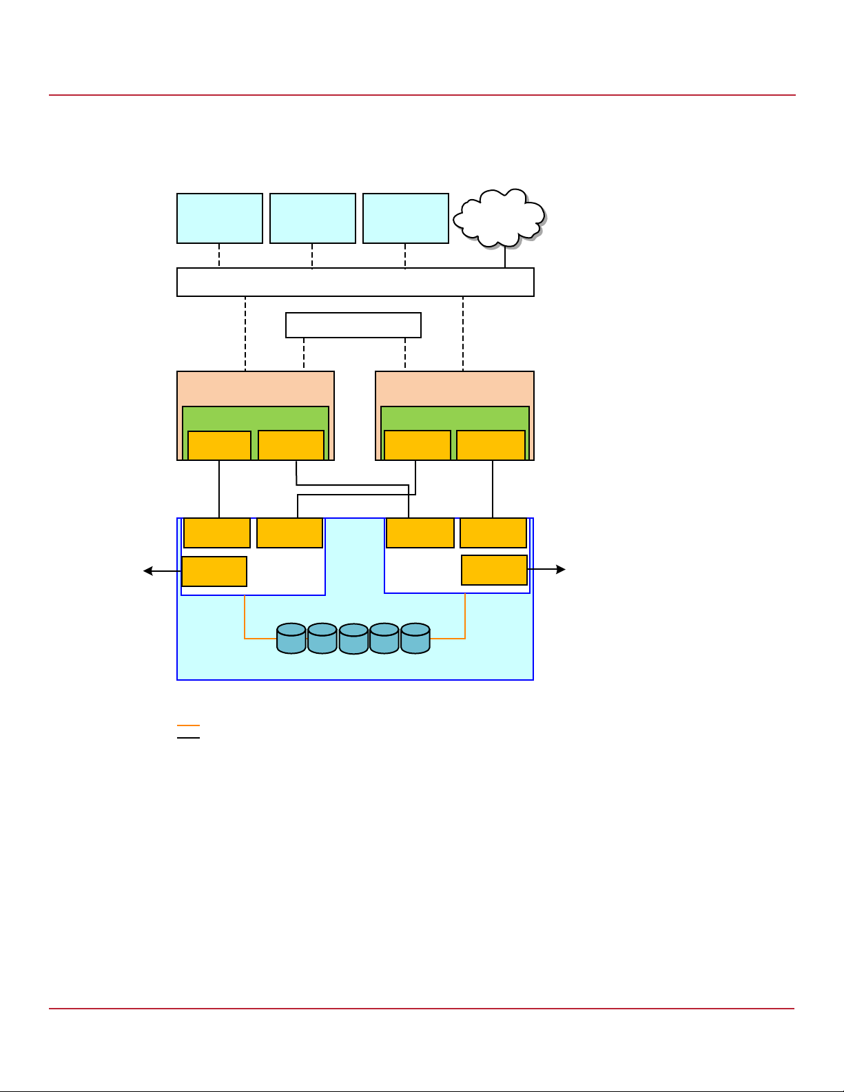
The following figure shows a high-level diagram of a CiB Syncro CS 9361-8i CiB configuration connected to a network.
The diagram includes the details of the SAS interconnections.
NOTE The CB220 Quanta CIBs midplane has two SAS 8088 connectors. You
can connect cables from these connectors to the enclosure external
storage modules (ESMs). You should connect two cables from each
port to the two ESM modules (one cable to a module) present in the
storage enclosure.
Avago Technologies
- 9 -
Page 10
Syncro CS 9361-8i and Syncro CS 9380-8e Controllers User Guide
November 2014
Figure 1 CiB Syncro CS 9361-8i Configuration
Syncro CS 9361-8i Cluster-in-a-Box Hardware Setup
Chapter 2: Hardware and Software Setup
L6&6,
&OLHQWZLWK
$SSOLFDWLRQV
6HUYHU1RGH
3RUWV
&L%([SDQGHU
%RDUG
L6&6,
&OLHQWZLWK
$SSOLFDWLRQV
L6&6,
&OLHQWZLWK
$SSOLFDWLRQV
3XEOLF/RFDO$UHD1HWZRUN/$1
3ULYDWH/$1
0RGXOH
L
3RUWV
&L%'ULYH%DFNSODQH
6HUYHU1RGH
L
3RUWV
1HWZRUN
'166HUYHU
0RGXOH
3RUWV
([SDQGHU([SDQGHU
&L%([SDQGHU
%RDUG
6$6'XDO3RUWHG'ULYHV
&OXVWHULQD%R[&KDVVLV
6$66LQJOH/DQHV
6$6)RXU/DQHV
B
2.2 Syncro CS 9361-8i Cluster-in-a-Box Hardware Setup
Follow these steps to set up the hardware for a Syncro CS 9361-8i CiB configuration. The setup procedure might be
somewhat different for CiB models from different vendors, so be sure to also read the CiB manufacturer’s
documentation.
NOTE The Syncro CS solution includes two Syncro CS controllers, so you
must perform the installation procedure for both controllers, one in
each server module inside the CiB enclosure.
1. Unpack the controller kit in a static-free environment and check the contents. Remove the components from the
antistatic bags and inspect them for damage. If any components are missing or damaged, contact LSI or your
Syncro CS OEM support representative.
2. Turn off power to the CiB enclosure, if necessary, and unplug the power cords from the power supply. Remove the
cover from the CiB.
Avago Technologies
- 10 -
Page 11

Syncro CS 9361-8i and Syncro CS 9380-8e Controllers User Guide
November 2014
CAUTION Before you install the Syncro CS controllers, make sure that the CiB
enclosure is disconnected from the power and from any networks.
3. Review the Syncro CS connectors and the jumper settings and change them if necessary.
You usually do not need to change the default factory settings of the jumpers. The following figure shows the
location of the jumpers and connectors on the controller board.
The CVFM04 module comes pre-installed on your Syncro CS 9361-8i controller; however, the module is not
attached in the following figure so that you can see all of the connectors and headers on the controller. Figure 5,
Figure 6, and Figure 7 show the controller with the CVFM04 module installed.
In the figure, Pin 1 is highlighted in red for each jumper.
Figure 2 Layout of the Syncro CS 9361-8i Controller
Syncro CS 9361-8i Cluster-in-a-Box Hardware Setup
Chapter 2: Hardware and Software Setup
J4B1
J1A2
J1A4
J1B1
3_01679-02
J2B4
J5B1
J6B1
J6B5
J5A1
J6B7
J6B2
J6B3
J6B6
J6B4
Avago Technologies
- 11 -
Page 12

Syncro CS 9361-8i and Syncro CS 9380-8e Controllers User Guide
November 2014
The following table describes the jumpers and connectors on the Syncro CS 9361-8i controller.
Table 1 Syncro CS 9361-8i Controller Jumpers and Connectors
Syncro CS 9361-8i Cluster-in-a-Box Hardware Setup
Chapter 2: Hardware and Software Setup
Jumper/
Connector
J1A2
J1A4
IPMI-style I
IPMI-style I
2
C connector for Ports 4 to 7
2
C connector for Ports 0 to 3
Typ e Description
J1B1 Individual PHY and drive fault indication
header
Ports 0 to 3
Ports 4 to 7
YH YH
DN
3257
3-pin connector
Supports SCSI Enclosure Services (SES) over I
2
C backplane cable.
I
2
C through an internal
3-pin connector
Supports SES over I
2
C through an internal I2C backplane cable.
2x8-pin header
Connects to an LED that indicates whether a drive is in a fault
condition. One LED exists per port. When lit, each LED indicates
the corresponding drive has failed or is in the Unconfigu-Bad state.
The LEDs function in a direct-attach configuration (no SAS
expanders exist). Direct attach is defined as a maximum of one
drive connected directly to each port.
The J5A1 connector on the MegaRAID SAS 9361-4i RAID controller
is a single internal port connector.
3257
-%
B
J2B4 Standard edge card connector The interface between the RAID controller and the host system.
Along with the PCIe
the board and an I
® interface, this connector provides power to
2
C interface connected to the I2C bus for the
Intelligent Platform Management Interface (IPMI).
J4B1 CacheVault Flash Module (ONFI) interface 70-pin connector
Connects the RAID controller to a flash module.
J5A1 Dual x4 SAS Port 0 through Port 7 internal
connector
Two SFF-8643 mini-SAS HD-4i internal connectors
Connects the controller by cable to SAS drives .
J5B1 LSI Test header 2-pin connector
Reserved for LSI use.
Avago Technologies
- 12 -
Page 13

Syncro CS 9361-8i and Syncro CS 9380-8e Controllers User Guide
November 2014
Table 1 Syncro CS 9361-8i Controller Jumpers and Connectors (Continued)
Syncro CS 9361-8i Cluster-in-a-Box Hardware Setup
Chapter 2: Hardware and Software Setup
Jumper/
Connector
J6B1 Advanced software options hardware key
header
Typ e Description
3-pin header
Enables support for selected advanced features, such as Recovery,
FastPath, and SafeStore™ disk encryption.
Refer to the MegaRAID Advanced Software Options Hardware Key
Quick Installation Guide for more information.
J6B2 Default Serial boot ROM (SBR) header 2-pin connector
Reserved for LSI use.
J6B3 Global hard disk drive (HDD) activity LED
header
2-pin connector
Connects to an LED that indicates activity on the drives connected
to the controller.
YH YH
DN
-%
B
J6B4 On-board Serial Universal Asynchronous
Receiver/Transmitter (UART) connector
4-pin connector
Reserved for LSI use.
J6B5 Global drive fault LED header 2-pin connector
Connects to an LED that indicates whether a drive is in a fault
condition
YHYH
DN
-%
B
J6B6 Complex programmable logic device (CPLD)
header
6-pin connector
Reserved for LSI use.
J6B7 Cache write pending header 2-pin connector.
Connector for an LED mounted on the system enclosure. The LED
indicates that the data in the cache has yet to be written to the
YHYH
DN
storage devices.
-%
B
Avago Technologies
- 13 -
Page 14

Syncro CS 9361-8i and Syncro CS 9380-8e Controllers User Guide
November 2014
4. Ground yourself and then place the Syncro CS controller and the remote mount board on a flat, clean, static-free
surface.
NOTE If you want to replace a bracket, refer to the Replacing Brackets on
MegaRAID SAS+SATA RAID Controllers Quick Installation Guide at
http://www.lsi.com/downloads/ for instructions.
5. Perform the following steps to attach the clip to a BBU-BRACKET-05 remote mount board.
a. With the remote mount board on a flat, clean, static-free surface, ground yourself, and make sure that the
system is grounded.
b. Remove the mounting clip and the remote mount board module from the package.
c. Place the clip and the remote mount board module front-side-up on a flat, clean, static-free surface.
d. Hold the clip so the screw holes on the clip line up with the screw holes on the remote mount board, as
shown in the following figure.
Figure 3 Installing the Clip on the Remote Mount Board
Syncro CS 9361-8i Cluster-in-a-Box Hardware Setup
Chapter 2: Hardware and Software Setup
A
A
Clip
A
3_00895b-00
e. Secure the clip to the three screw holes with the screws and the nuts.
The screws thread through the front of the clip and the remote mount board.
NOTE Center the screwdriver carefully to avoid stripping the screw heads. Do
not over-tighten the screws.
Avago Technologies
- 14 -
Page 15

Syncro CS 9361-8i and Syncro CS 9380-8e Controllers User Guide
November 2014
6. Perform the following steps to attach the CVPM02 module to the clip.
a. Ground yourself, and make sure that the system is grounded.
b. Remove the CVPM02 module from the package.
c. Place the CVPM02 module front-side-up on a flat, clean, static-free surface.
d. Press the CVPM02 module into the clip until the module clicks firmly into place, as shown in the following
figure.
Figure 4 Attaching the CVPM02 Module to the Clip
A
Syncro CS 9361-8i Cluster-in-a-Box Hardware Setup
Chapter 2: Hardware and Software Setup
Clip
CacheVault
Power Module
3_01275b-00
Avago Technologies
- 15 -
Page 16
Syncro CS 9361-8i and Syncro CS 9380-8e Controllers User Guide
November 2014
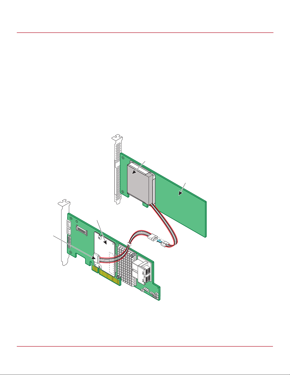
7. Follow these steps to connect the CVFM04 module on your Syncro CS controller by cable to the remote CVPM02
module.
NOTE The CVFM04 modules come pre-installed on the Syncro CS 9361-8i
controllers.
a. Place the controller on a flat, clean, static-free surface.
b. Ground yourself, and make sure that the system is grounded.
c. Remove the cable that is included in the box.
The cable has a 9-pin connector on one end and a 6-pin connector on the other.
d. Insert the 9-pin connector on the cable into the 9-pin J1 connector on the CVFM04 module, as shown in the
following figure.
e. Insert the 6-pin connector into the 6-pin connector on the cable from the remote CVPM02 module.
Align the cable connectors to make sure that they are connected correctly.
Figure 5 Connecting the CVFM04 Module by Cable to the Remote CVPM02 Module
Syncro CS 9361-8i Cluster-in-a-Box Hardware Setup
Chapter 2: Hardware and Software Setup
CacheVault
Power Module 02
(CVPM02)
J1
Remote Mount
Board
CacheVault
Flash Module 04
(CVFM04)
3_01657-04
Avago Technologies
- 16 -
Page 17
Syncro CS 9361-8i and Syncro CS 9380-8e Controllers User Guide
November 2014
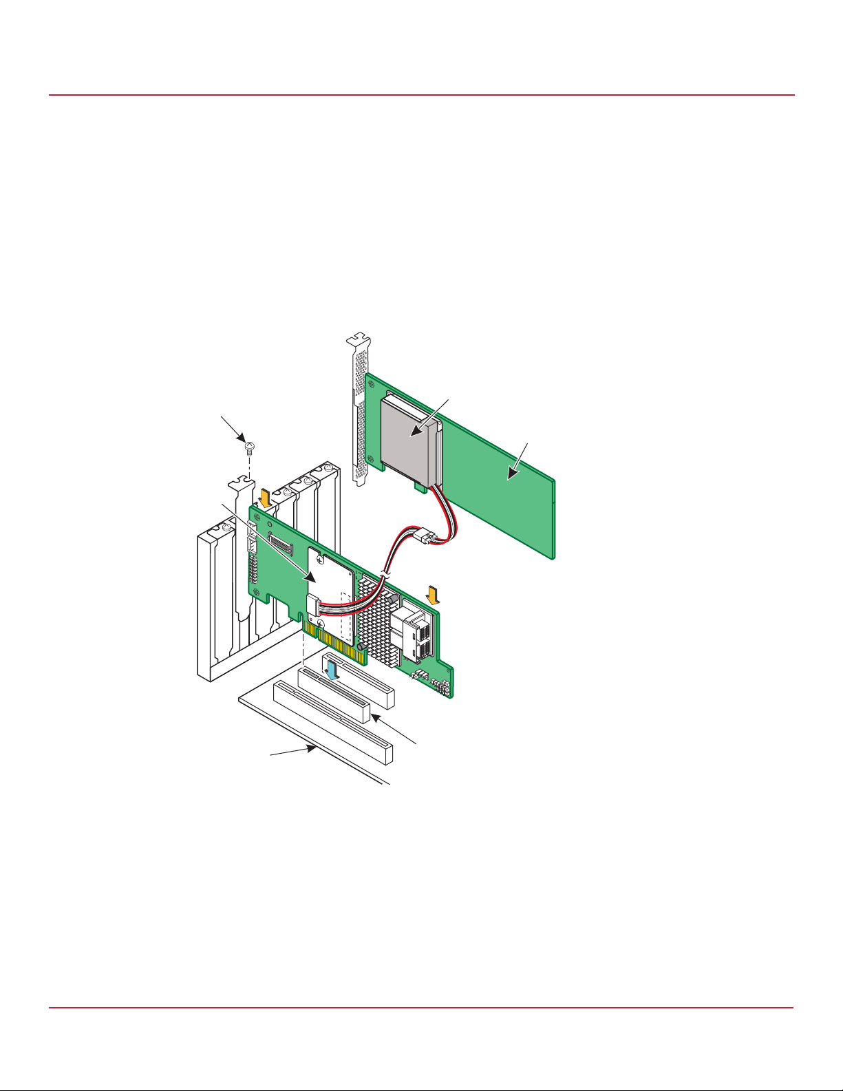
8. Follow these steps to reinstall your Syncro CS 9361-8i controller in a PCIe slot on the motherboard.
a. Make sure that the power to the chassis is still turned off, the power cords are unplugged, and the chassis is
grounded and has no AC power.
b. Install the controller in a PCIe slot on the motherboard, as shown in the following figure.
NOTE Some PCIe slots support only PCIe graphics cards; a controller installed
in one of these slots will not function. Refer to your computer
documentation for information about the PCIe slot.
c. Press down gently, but firmly, to seat the card correctly in the slot.
d. Secure the controller to the computer chassis with the bracket screw.
Figure 6 Reinstalling the Controller
Bracket
Screw
Syncro CS 9361-8i Cluster-in-a-Box Hardware Setup
Chapter 2: Hardware and Software Setup
CacheVault
Power Module 02
(CVPM02)
Remote Mount
Board
CacheVault
Flash Module 04
(CVFM04)
3_01658-04
Motherboard
Edge of
Press
Here
Press
Here
PCIe Slot
Avago Technologies
- 17 -
Page 18
Syncro CS 9361-8i and Syncro CS 9380-8e Controllers User Guide
November 2014
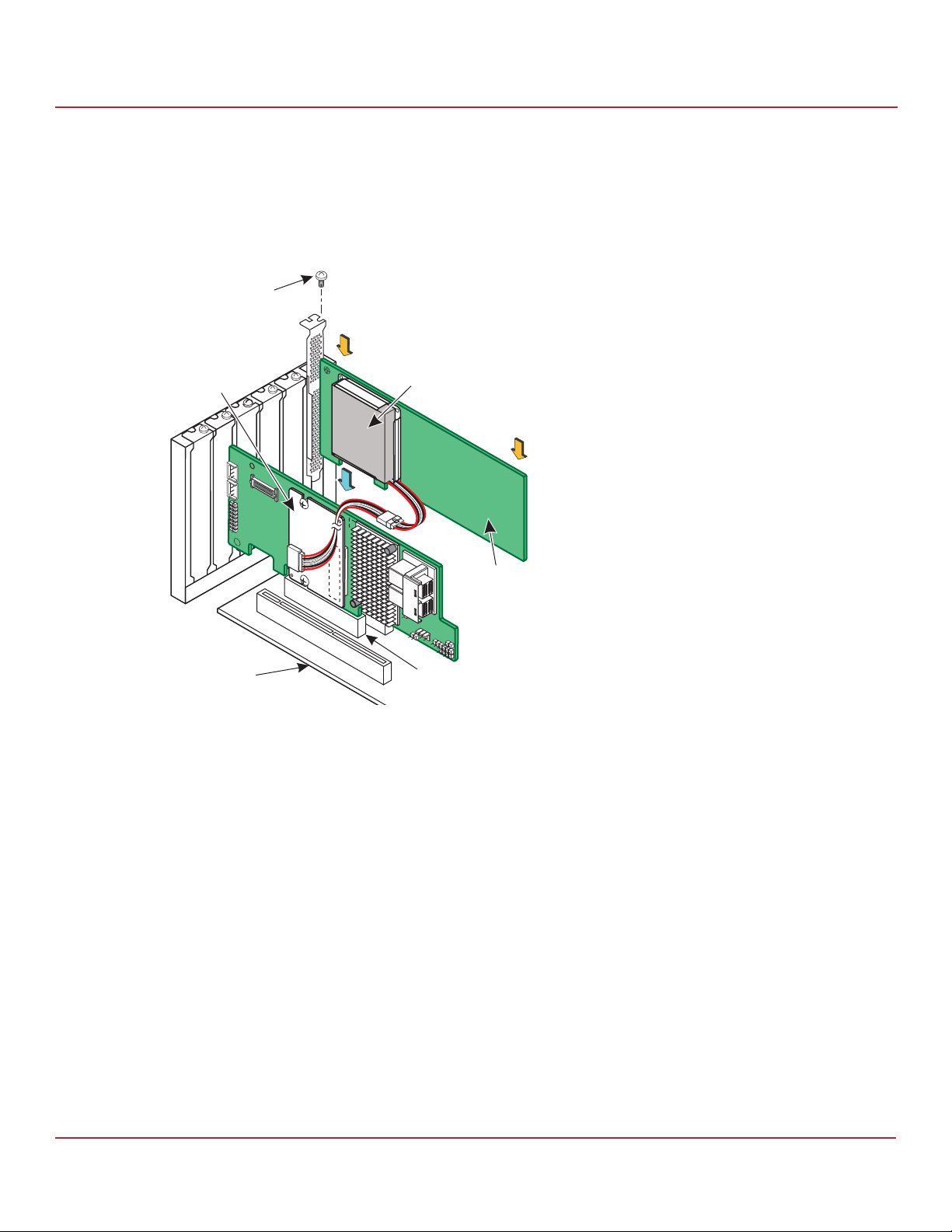
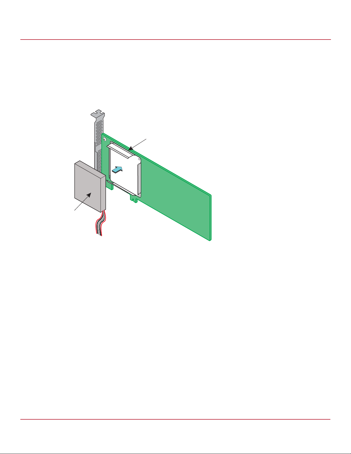
9. Follow these steps to install the remote mount board on the motherboard.
a. Insert the remote mount board in a PCIe slot on the motherboard, as shown in the following figure
b. Press down gently, but firmly, to seat the board correctly in the slot.
c. Use the bracket screw to secure the remote mount board to the system chassis.
Figure 7 Installing the Remote Mount Board
Bracket
Screw
Press
Here
CacheVault
Flash Module 04
(CVFM04)
Syncro CS 9361-8i Cluster-in-a-Box Hardware Setup
Chapter 2: Hardware and Software Setup
CacheVault
Power Module 02
(CVPM02)
Press
Here
Remote Mount
Board
3_01659-04
Edge of
Motherboard
PCIe Slot
10. Repeat step 4 to step 9 to install the second Syncro CS controller and the CVPM02 module in the second server
module of the CiB enclosure.
11. If necessary, install SAS disk drives in the CiB enclosure.
NOTE Drives that are used in the LSI Syncro CS solution must be selected
from the compatibility list that LSI maintains on its website. See the
URL for this compatibility list in Section 1.4, Hardware Compatibility.
12. Use SAS cables to connect the internal connectors of the Syncro CS controllers to SAS devices in the CiB
enclosure. Refer to the CiB manufacturer’s documentation for information on connecting SAS cables.
NOTE CiB chassis manufacturers determine the availability and
configuration of external JBOD storage expansion connections. Refer
to the instructions from the CiB vendor on how to properly configure
SAS cable connections for external JBOD enclosures, if your CiB chassis
offers this capability. Also, see the LSI hardware compatibility list at the
UL listed in Section 1.4, Hardware Compatibility.
Avago Technologies
- 18 -
Page 19

Syncro CS 9361-8i and Syncro CS 9380-8e Controllers User Guide
November 2014
13. Reinstall the cover of the CiB enclosure and reconnect the power cords. Turn on the power to the CiB enclosure.
The firmware takes several seconds to initialize. During this time, the controllers scan the ports.
Refer to the 12Gb/s MegaRAID SAS Software User Guide at http://www.lsi.com/downloads/ for information about
running the configuration utilities and installing the software drivers.
Refer to the Syncro CS 9361-8i and Syncro CS 9380-8e Solution User Guide at http://www.lsi.com/downloads/ for the
procedures used to create the HA-DAS cluster configuration after the hardware is fully configured and the
operating system is installed.
2.3 Syncro CS 9380-8e Controller Kit
The LSI Syncro CS 9380-8e controller kit includes the following items:
— Two Syncro CS 9380-8e controllers
— Two CacheVault Flash Modules 04 (CVFM04) (pre-installed on the controllers)
— Two CacheVault Power Modules 02 (CVPM02)
— Two CVPM02 mounting clips and hardware
— Two CVPM02 extension cables
— Two low-profile brackets
— Syncro CS 9361-8i and Syncro CS 9380-8e Controllers Getting Started Guide
Chapter 2: Hardware and Software Setup
Syncro CS 9380-8e Controller Kit
The hardware configuration for the Syncro CS 9380-8e solution requires the following additional hardware that is not
included in the kit:
— Two server modules from the LSI-approved compatibility list. The servers must include network cards.
— One or more JBOD enclosures with SAS disk drives from the LSI-approved compatibility list.
— A monitor and mouse for each server node.
— Network cabling and SAS cabling to connect the servers and JBOD enclosures.
Avago Technologies
- 19 -
Page 20
Syncro CS 9361-8i and Syncro CS 9380-8e Controllers User Guide
November 2014
The following figure shows a high-level diagram of a Syncro CS 9380-8e solution connected to a network and to a
single enclosure.
Figure 8 Two-Server Syncro CS 9380-8e Configuration with Single Enclosure
Chapter 2: Hardware and Software Setup
Syncro CS 9380-8e Controller Kit
L6&6,
&OLHQWZLWK
$SSOLFDWLRQV
L6&6,
&OLHQWZLWK
$SSOLFDWLRQV
3XEOLF/RFDO$UHD1HWZRUN/$1
6HUYHU1RGH$
&KDVVLV
6\QFUR&6H
7RS
&RQQHFWRU
&RQQHFWRU&RQQHFWRU
&RQQHFWRU
%RWWRP
&RQQHFWRU
([SDQGHU$
3ULYDWH/$1
L6&6,
&OLHQWZLWK
$SSOLFDWLRQV
6HUYHU1RGH%
&KDVVLV
6\QFUR&6H
7RS
&RQQHFWRU
&RQQHFWRU
&RQQHFWRU&RQQHFWRU
&RQQHFWRU
([SDQGHU%
1HWZRUN
'166HUYHU
%RWWRP
([WHUQDO-%2'6$6'ULYH(QFORVXUH
1RWH ([SDQGHU$FRQQHFWVWR3RUW$RIWKH6$6GULYHV
([SDQGHU%FRQQHFWVWR3RUW%RIWKH6$6GULYHV
6$66LQJOH/DQHV
6$6)RXU/DQHV
Avago Technologies
B
- 20 -
Page 21
Syncro CS 9361-8i and Syncro CS 9380-8e Controllers User Guide
November 2014
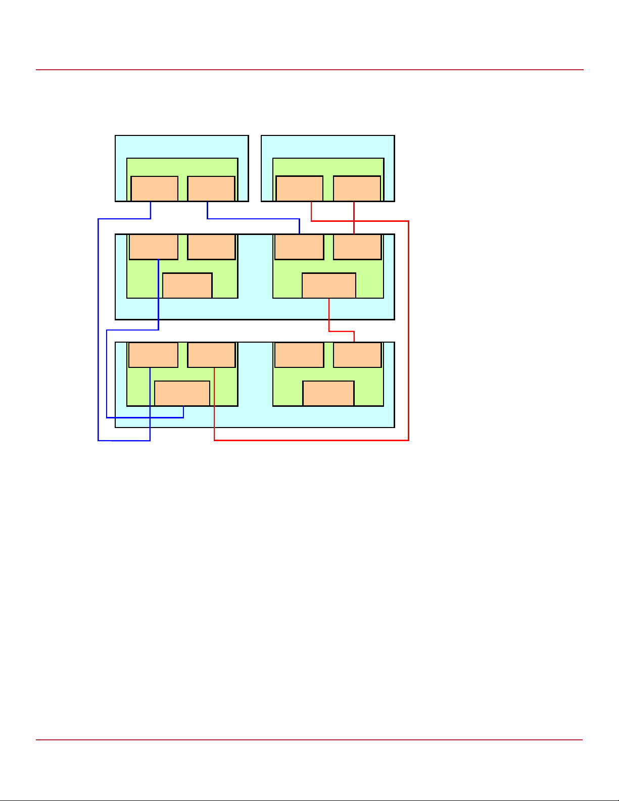
The following figure shows a high-level diagram of a Syncro CS 9380-8e solution with the controllers connected to
multiple enclosures.
Figure 9 Two-Server Syncro CS 9380-8e Configuration with Multiple Enclosures
Syncro CS 9380-8e Two-Server Cluster Hardware Setup
Chapter 2: Hardware and Software Setup
6HUYHU1RGH$
6\QFUR&6H
7RS
&RQQHFWRU
&RQQHFWRU
,Q
([SDQGHU$
&RQQHFWRU
2XW
&RQQHFWRU
,Q
([SDQGHU$
&RQQHFWRU
2XW
%RWWRP
&RQQHFWRU
&RQQHFWRU
,Q
'ULYH(QFORVXUH$
&RQQHFWRU
,Q
'ULYH(QFORVXUH%
6HUYHU1RGH%
6\QFUR&6H
7RS
&RQQHFWRU
&RQQHFWRU
,Q
([SDQGHU%
&RQQHFWRU
2XW
&RQQHFWRU
,Q
([SDQGHU%
&RQQHFWRU
2XW
%RWWRP
&RQQHFWRU
&RQQHFWRU
,Q
&RQQHFWRU
,Q
B
2.4 Syncro CS 9380-8e Two-Server Cluster Hardware Setup
Perform the following steps to set up the hardware for a Syncro CS 9380-8e configuration.
1. Unpack the Syncro CS 9380-8e controllers and the CVPM02 modules from the kit and inspect them for damage.
If any components of the kit appear to be damaged, or if any items are missing from the kit, contact your LSI
Customer and Technical Support representative.
2. Turn off the power to the server units, disconnect the power cords, and disconnect any network cables.
3. Remove the covers from the two server units.
Refer to the server documentation for instructions on how to do this.
4. Review the Syncro CS 9380-8e jumper settings and change them if necessary. Also note the location of the
external Mini-SAS SFF8644 connector J1A12.
You usually do not need to change the default factory settings of the jumpers. The following figure shows the
location of the jumpers and connectors on the controller board.
The CVFM04 module comes pre-installed on the Syncro CS controller; however, the module is not included in the
following figure so that you can see all of the connectors and headers on the controller board. Figure 13,
Figure 14, and Figure 15 show the controller with the CVFM04 module installed.
Avago Technologies
- 21 -
Page 22

Syncro CS 9361-8i and Syncro CS 9380-8e Controllers User Guide
November 2014
In the figure, Pin 1 is highlighted in red for each jumper.
Figure 10 Card Layout for the Syncro CS 9380-8e Controller
Syncro CS 9380-8e Two-Server Cluster Hardware Setup
Chapter 2: Hardware and Software Setup
J1A11 J4A1J1A5
J1A8
J1A12
J1B2
J1B4
J1B3
J1A6
J1B1
3_02175-03
J2B4
The following table describes the jumpers and the connectors on the Syncro CS 9380-8e controller.
Table 2 Syncro CS 9380-8e Jumpers and Connectors
Jumper/
Connector
J1A5 Default Serial boot ROM (SBR) header 2-pin connector
J1A6 Global drive fault LED header 2-pin connector
YH YH
DN
Typ e Description
Reserved for LSI use.
Connects to an LED that indicates activity on the drives connected to
the controller.
-$
B
J1A8 CPLD header 5-pin connector
Reserved for LSI use.
Avago Technologies
- 22 -
Page 23

Syncro CS 9361-8i and Syncro CS 9380-8e Controllers User Guide
November 2014
Table 2 Syncro CS 9380-8e Jumpers and Connectors (Continued)
Syncro CS 9380-8e Two-Server Cluster Hardware Setup
Chapter 2: Hardware and Software Setup
Jumper/
Connector
J1A11 Global hard disk drive (HDD) activity LED
header
Typ e Description
2-pin connector
Connects to an LED that indicates activity on the drives connected to
the controller.
YH YH
DN
-$
B
J1A12 SAS Port 0 through Port 7 external
connector
J1B1 Advanced software options hardware key
header
Two SFF-8644 mini-SAS HD-4e external connectors
Connects the controller by cable to an enclosure containing SAS drives.
3-pin header
Enables support for selected advanced features, such as Recovery,
FastPath, and SafeStore™ disk encryption.
Refer to the MegaRAID Advanced Software Options Hardware Key Quick
Installation Guide for more information.
J1B2 Cache write pending header 2-pin connector.
Connector for an LED mounted on the system enclosure. The LED
indicates that the data in the cache has yet to be written to the
YH YH
DN
storage devices.
-%
B
J1B3 LSI Test header 2-pin connector
Reserved for LSI use.
J1B4 On-board Serial Universal Asynchronous
Receiver/Transmitter (UART) connector
4-pin connector
Reserved for LSI use.
J2B4 Standard edge card connector The interface between the RAID controller and the host system.
Along with the PCIe interface, this connector provides power to the
board and an I
2
C interface connected to the I2C bus for the Intelligent
Platform Management Interface (IPMI).
J4A1 CacheVault Flash Module (ONFI) interface 80-pin connector
Connects the RAID controller to a flash module.
5. Ground yourself and then place the Syncro CS controller on a flat, clean, static-free surface.
NOTE If you want to replace a bracket, refer to the Replacing Brackets on
MegaRAID SAS+SATA RAID Controllers Quick Installation Guide at
http://www.lsi.com/downloads/ for instructions.
Avago Technologies
- 23 -
Page 24

Syncro CS 9361-8i and Syncro CS 9380-8e Controllers User Guide
November 2014
6. Perform the following steps to attach the clip to a BBU-BRACKET-05 remote mount board.
a. With the remote mount board on a flat, clean, static-free surface, ground yourself, and make sure that the
system is grounded.
b. Remove the mounting clip and the remote mount board module from the package.
c. Place the clip and the remote mount board module front-side-up on a flat, clean, static-free surface.
d. Hold the clip so the screw holes on the clip line up with the screw holes on the remote mount board, as
shown in the following figure.
e. Secure the clip to the three screw holes with the screws and the nuts.
The screws thread through the front of the clip and the remote mount board.
NOTE Center the screwdriver carefully to avoid stripping the screw heads. Do
not over-tighten the screws.
Figure 11 Installing the Clip on the Remote Mount Board
A
Syncro CS 9380-8e Two-Server Cluster Hardware Setup
Chapter 2: Hardware and Software Setup
Clip
A
A
3_00895b-00
Avago Technologies
- 24 -
Page 25
Syncro CS 9361-8i and Syncro CS 9380-8e Controllers User Guide
November 2014
7. Perform the following steps to attach the CVPM02 module to the clip.
a. Ground yourself, and make sure that the system is grounded.
b. Remove the CVPM02 module from the package.
c. Place the CVPM02 module front-side-up on a flat, clean, static-free surface.
d. Press the CVPM02 module into the clip until the module clicks firmly into place, as shown in the following
figure.
Figure 12 Attaching the CVPM02 Module to the Clip
A
Syncro CS 9380-8e Two-Server Cluster Hardware Setup
Chapter 2: Hardware and Software Setup
Clip
CacheVault
Power Module
3_01275b-00
Avago Technologies
- 25 -
Page 26

Syncro CS 9361-8i and Syncro CS 9380-8e Controllers User Guide
November 2014
8. Follow these steps to connect the CVFM04 module on your Syncro CS controller by cable to the remote CVPM02
module.
NOTE The CVFM04 modules come pre-installed on the Syncro CS 9380-8e
controllers.
a. Place the controller on a flat, clean, static-free surface.
b. Ground yourself, and make sure that the system is grounded.
c. Remove the cable that is included in the box.
The cable has a 9-pin connector on one end and a 6-pin connector on the other.
d. Insert the 9-pin connector on the cable into the 9-pin J1 connector on the CVFM04 module, as shown in the
following figure.
e. Insert the 6-pin connector into the 6-pin connector on the cable from the remote CVPM02 module.
Align the cable connectors to make sure that they are connected correctly.
Figure 13 Connecting the CVFM04 Module by Cable to the Remote CVPM02 Module
CacheVault
Power Module 02
(CVPM02)
Syncro CS 9380-8e Two-Server Cluster Hardware Setup
Chapter 2: Hardware and Software Setup
3_02396-01
CacheVault
Flash Module 04
(CVFM04)
Remote Mount
Board
J1
Avago Technologies
- 26 -
Page 27

Syncro CS 9361-8i and Syncro CS 9380-8e Controllers User Guide
November 2014
9. Follow these steps to reinstall your Syncro CS 9380-8e controller in a PCIe slot on the motherboard.
a. Make sure that the power to the chassis is still turned off, the power cords are unplugged, and the chassis is
grounded and has no AC power.
b. Install the controller in a PCIe slot on the motherboard, as shown in the following figure.
NOTE Some PCIe slots support only PCIe graphics cards; a controller installed
in one of these slots will not function. Refer to your computer
documentation for information about the PCIe slot.
c. Press down gently, but firmly, to seat the card correctly in the slot.
d. Secure the controller to the computer chassis with the bracket screw.
Figure 14 Reinstalling the Controller
Bracket
Screw
Press
Here
Flash Module 04
CacheVault
(CVFM04)
CacheVault
Power Module 02
(CVPM02)
Syncro CS 9380-8e Two-Server Cluster Hardware Setup
Remote Mount
Chapter 2: Hardware and Software Setup
Board
3_02397-00
Edge of
Motherboard
Press
Here
PCIe Slot
Avago Technologies
- 27 -
Page 28

Syncro CS 9361-8i and Syncro CS 9380-8e Controllers User Guide
November 2014
10. Follow these steps to install the remote mount board on the motherboard.
a. Insert the remote mount board in a PCIe slot on the motherboard, as shown in the following figure
b. Press down gently, but firmly, to seat the board correctly in the slot.
c. Use the bracket screw to secure the remote mount board to the system chassis.
Figure 15 Installing the Remote Mount Board
Bracket
Screw
CacheVault
Flash Module 04
(CVFM04)
Press
Here
CacheVault
Power Module 02
(CVPM02)
Remote Mount
Board
Syncro CS 9380-8e Two-Server Cluster Hardware Setup
Chapter 2: Hardware and Software Setup
Press
Here
3_02398-00
Edge of
Motherboard
PCIe Slot
11. Repeat step 4 to step 10 to install the second Syncro CS controller and the CVPM02 module in the second server
module of the CiB enclosure.
12. If necessary, install SAS disk drives in the CiB enclosure.
NOTE Drives that are used in the LSI Syncro CS solution must be selected
from the compatibility list that LSI maintains on its website. See the
URL for this compatibility list in Section 1.4, Hardware Compatibility.
13. Use SAS cables to connect the internal connectors of the Syncro CS controllers to SAS devices in the CiB
enclosure. Refer to the CiB manufacturer’s documentation for information on connecting SAS cables.
NOTE CiB chassis manufacturers determine the availability and
configuration of external JBOD storage expansion connections. Refer
to the instructions from the CiB vendor on how to properly configure
SAS cable connections for external JBOD enclosures, if your CiB chassis
offers this capability. Also, see the LSI hardware compatibility list at the
UL listed in Section 1.4, Hardware Compatibility.
14. Reinstall the cover of the CiB enclosure and reconnect the power cords. Turn on the power to the CiB enclosure.
The firmware takes several seconds to initialize. During this time, the controllers scan the ports.
Avago Technologies
- 28 -
Page 29

Syncro CS 9361-8i and Syncro CS 9380-8e Controllers User Guide
November 2014
Refer to the 12Gb/s MegaRAID SAS Software User Guide at http://www.lsi.com/downloads/ for information about
running the configuration utilities and installing the software drivers.
Refer to the Syncro CS 9361-8i and Syncro CS 9380-8e Solution User Guide at http://www.lsi.com/downloads/ for the
procedures used to create the HA-DAS cluster configuration after the hardware is fully configured and the
operating system is installed.
2.5 Syncro CS Cluster-in-a-Box Software Setup
Perform the following steps to set up the software for a Syncro CS CiB configuration.
1. Configure the drive groups and the virtual drives on the two controllers.
For specific instructions, refer to the Syncro CS 9361-8i and Syncro CS 9380-8e Solution User Guide at
http://www.lsi.com/downloads/. You can use the WebBIOS, StorCLI, or MegaRAID Storage Manager configuration
utilities to create the groups and virtual drives.
2. Install the operating system driver on both server nodes.
You must install the software driver first, before you install the operating system.
You can view the supported operating systems and download the latest drivers for the Syncro CS controllers from
the LSI website at http://www.lsi.com/support/Pages/download-search.aspx. Access the download center, and
follow the steps to download the appropriate driver.
Refer to the MegaRAID SAS Device Driver Installation User Guide at http://www.lsi.com/downloads/ for more
information about installing the driver. Be sure to review the readme file that accompanies the driver.
3. Install the operating system on both server nodes, following the instructions from the operating system vendor.
Make sure you apply all of the latest operating system updates and service packs to ensure proper functionality.
You have two options for installing the operating system for each controller node:
— Install it on a private volume connected to the system-native storage controller. The recommended best
practice is to install the operating system on this private volume because the disks in the clustering
configuration cannot see this volume. Therefore, no danger exists of accidentally overwriting the operating
system disk when you set up clustering.
— Install it on an exclusive virtual drive connected to the Syncro CS controller. Exclusive host access is required
for a boot volume so the volume is not overwritten accidentally when you create virtual drives for data
storage. For instructions on how to create exclusive virtual drives using the WebBIOS utility, refer to the
Syncro CS 9361-8i and Syncro CS 9380-8e Solution User Guide at http://www.lsi.com/downloads/.
Chapter 2: Hardware and Software Setup
Syncro CS Cluster-in-a-Box Software Setup
NOTE The Syncro CS solution does not support booting from a shared
operating system volume.
4. Install StorCLI and MegaRAID Storage Manager for the Windows® and Linux® operating systems following the
installation steps outlined in the StorCLI Reference Manual and 12Gb/s MegaRAID SAS Software User Guide at
http://www.lsi.com/downloads/.
Avago Technologies
- 29 -
Page 30

Syncro CS 9361-8i and Syncro CS 9380-8e Controllers User Guide
November 2014
Revision History
Version 2.0, November 2014
Revised Section 1.6, Performance Considerations and Figure 1. Added a link to the download page on the LSI.com
website.
Version 1.0, August 2014
Initial release of this document.
Revision History
Avago Technologies
- 30 -
Page 31

 Loading...