

Page 1

USER’S
GUIDE
MegaRAID
®
Configuration Software
March 2006
Version 2.0
®
DB15-000269-01
Page 2

This document contains proprietary information of LSI Logic Corporation. The
information contained herein is not to be used by or disclosed to third parties
without the express written permission of an officer of LSI Logic Corporation.
LSI Logic products are not intended for use in life-support appliances, devices,
or systems. Use of any LSI Logic product in such applications without written
consent of the appropriate LSI Logic officer is prohibited.
2
Purchase of I
Associated Companies, conveys a license under the Philips I
use these components in an I
2
C standard Specification as defined by Philips.
the I
C components of LSI Logic Corporation, or one of its sublicensed
2
C system, provided that the system conforms to
2
C Patent Rights to
Document DB15-000269-01, Second Edition (March 2006)
This document describes LSI Logic Corporation’s MegaRAID software tools and
utilities. This document will remain the official reference source for all
revisions/releases of these products until rescinded by an update.
LSI Logic Corporation reserves the right to make changes to any products herein
at any time without notice. LSI Logic does not assume any responsibility or
liability arising out of the application or use of any product described herein,
except as expressly agreed to in writing by LSI Logic; nor does the purchase or
use of a product from LSI Logic convey a license under any patent rights,
copyrights, trademark rights, or any other of the intellectual property rights of
LSI Logic or third parties.
Copyright © 2003–2006 by LSI Logic Corporation. All rights reserved.
TRADEMARK ACKNOWLEDGMENT
LSI Logic, the LSI Logic logo design, FlexRAID, MegaRAID, MegaRAID
Configuration Utility, MegaRAID Manager, and Power Console Plus are
trademarks or registered trademarks of LSI Logic Corporation. Intel and Pentium
are registered trademarks of Intel Corporation. Linux is a registered trademark of
Linus Torvalds. Microsoft, MS-DOS, Windows, and Windows NT are registered
trademarks of Microsoft Corporation. NetWare,Novell, and SUSE are trademarks
or registered trademarks of Novell, Inc. PCI-X is a registered trademark of PCI
SIG. Red Hat is a registered trademark of Red Hat Software, Inc. All other brand
and product names may be trademarks of their respective companies.
CD
To receive product literature, visit us at http://www.lsilogic.com.
For a current list of our distributors, sales offices, and design resource
centers, view our web page located at
http://www.lsilogic.com/contacts/index.html
ii
Version 2.0 Copyright © 2003–2006 by LSI Logic Corporation. All rights reserved.
Page 3

Preface
Audience
This book is the primary reference and user’s guide for the MegaRAID
software tools and utilities. These include the MegaRAID BIOS
Configuration Utility (CU), WebBIOS CU, MegaRAID Manager™, and
Power Console Plus™, which enable configuration and management of
RAID systems using the MegaRAID controllers.
This document assumes that you have familiarity with storage systems,
and are knowledgeable about PCI, SCSI, and Serial ATA interfaces. It
also assumes that you are familiar with computer systems and know how
to use the keyboard, mouse, clipboard functions, toolbars, and drop
down menus.
The people who benefit from this book are:
• Users who want to configure, monitor, or manage RAID systems that
use MegaRAID controllers
• Engineers and managers who are evaluating MegaRAID controllers
for use in a system
• Engineers who are designing MegaRAID controllers into a system
®
Organization
This document has the following chapters and appendix:
• Chapter 1, Overview, introduces the MegaRAID software tools and
utilities, and provides operating system information.
• Chapter 2, Introduction to RAID, describes the components,
functions and benefits of RAID, along with RAID levels, configuration
strategies, and configuration planning.
MegaRAID Configuration Software User’s Guide iii
Version 2.0 Copyright © 2003–2006 by LSI Logic Corporation. All rights reserved.
Page 4

• Chapter 3, BIOS Configuration Utility and MegaRAID Manager,
describes the MegaRAID BIOS CU.
• Chapter 4, WebBIOS Configuration Utility, describes the
WebBIOS CU.
• Chapter 5, Start the Power Console Plus Utility, describes the
Power Console Plus tool.
• Chapter 6, Virtual Sizing and Online Capacity Expansion,
describes the FlexRAID Virtual Sizing feature and capacity
expansion under Linux.
• Appendix A, MegaRAID Service Monitor, describes the messages
used by the MegaRAID Service Monitor.
MegaRAID System Installation Sequences and Document Organization
The following table outlines the installation, configuration, and
management sequences for a MegaRAID Serial ATA system. Each
sequence consists of a series of steps and operations that the reference
manual explains. LSI Logic recommends performing the sequences in
the order listed when you install and configure your Serial ATA system.
Sequence Task Reference Manual
1 Understand RAID system theory and operation. MegaRAID Configuration
2 Install the MegaRAID Serial ATA (SATA) or SCSI storage
3 Configure the physical arrays and logical devices using
4 Install the MegaRAID device drivers. MegaRAID Device Driver
5 Manage, monitor, and reconfigure the RAID array using
iv Preface
adapter and the related hardware.
either the MegaRAID Configuration Utility
WebBIOS CU.
either the MegaRAID Manager tool or the Power Console
Plus tool. Each tool runs under an operating system and
can manage the RAID array while the system is operating.
Version 2.0 Copyright © 2003–2006 by LSI Logic Corporation. All rights reserved.
™
(CU) or the
Software User’s Guide
MegaRAID 320 Storage
Adapters User’s Guide,
MegaRAID SATA150 PCI to
Serial ATA Storage Adapters
User’sGuide, and MegaRAID
SATA 300 Storage Adapters
User’s Guide
MegaRAID Configuration
Software User’s Guide
Installation User’s Guide
MegaRAID Configuration
Software User’s Guide
Page 5

Related Publications
MegaRAID SA TA150 PCI to Serial ATA Storage Adapters User’s Guide
Document Number: DB15-000272-04
This document explains how to install your MegaRAID SATA 150 storage
adapter in the host system. It provides the electrical and physical
specifications, jumper definitions, and connector locations for the
storage adapter.
MegaRAID SATA 300 Storage Adapters User’s Guide
Document Number: DB15-000311-02
This document explains how to install your MegaRAID SATA 300 storage
adapter in the host system. It provides the electrical and physical
specifications, jumper definitions, and connector locations for the
storage adapter.
MegaRAID 320 Storage Adapters User’s Guide
Document Number: DB15-000260-06
This document explains how to install your MegaRAID 320 storage
adapter in the host system. It provides the electrical and physical
specifications, jumper definitions, and connector locations for the
storage adapter.
MegaRAID Device Driver Installation User’s Guide
Document Number: DB11-000018-02
This document explains how to install the MegaRAID device driver for
your operating system. The information in this document is independent
of the back-end bus and applies to both MegaRAID SCSI storage
adapters and Serial ATA storage adapters.
Preface v
Version 2.0 Copyright © 2003–2006 by LSI Logic Corporation. All rights reserved.
Page 6

Conventions
Throughout the manual, the following conventions are used to describe
user interaction with the product.
Notation Meaning and Use Examples
→ Used to indicate a series of
all caps,
plus sign
courier
typeface
bold typeface fd1sp In a command line, keywords are shown in bold, nonitalic
italics module In command lines and names, italics indicate user
Initial Capital letters
brackets [version] You may, but need not, select one item enclosed within
selections in a GUI.
Key presses are in all caps,
with a plus sign (+) between
key presses in a sequence
.nwk file Names of commands, directories, file names, and
Undo
Edit
Apply
Start → Programs
ENTER, ALT+CTRL+DEL, TAB
on-screen text are shown in courier typeface.
typeface. Enter them exactly as shown.
variables. Italicized text must be replaced with appropriate
user-specified items. Enter items of the type called for,
using lowercase.
Names of menu commands, options, check buttons, text
buttons, options buttons, text boxes, list boxes, etc., are
shown in text with Initial Capital lettering to avoid
misreading. These elements may appear on your screen
in all lowercase.
brackets. Do not enter the brackets.
vi Preface
Version 2.0 Copyright © 2003–2006 by LSI Logic Corporation. All rights reserved.
Page 7
Revision History
Document Number Version/Date Description
DB15-000269-01 Version 2.0
February 2006
DB15-000269-00 Version 1.0
February 2003
Technical Support
LSI provides technical support only for LSI products purchased directly
from LSI or from an LSI-authorized reseller.
If you purchased the MegaRAID controller from LSI or from a certified
LSI reseller, call LSI technical support at support@lsil.com,
1-800-633-4545 #3, or 1-678-728-1250. Please be prepared to specify
the 10-digit number preceded by the letter “E”.
In Europe, you can contact LSI Technical Support at
eurosupport@lsil.com or +44.1344.413.441 (English).
If the MegaRAID controller was installed as part of a system
manufactured by a company other than LSI, or if you purchased an LSI
product from an unauthorized reseller, call the technical support
department of the computer manufacturer or the unauthorized reseller.
LSI does not provide direct technical support in these cases.
Added the introduction to RAID chapter. Revised
supported operating systems, spanning, and menu
options, and added port multiplier information in the BIOS
Configuration Utility. Revised information about virtual
sizing. Revised the WebBIOS Adapter Properties Menu
and the Configuration Wizard procedure.
Initial release of document.
To download drivers or documentation, go to the LSI web site at:
http://www.lsilogic.com/downloads/selectDownload.do.
Preface vii
Version 2.0 Copyright © 2003–2006 by LSI Logic Corporation. All rights reserved.
Page 8

viii Preface
Version 2.0 Copyright © 2003–2006 by LSI Logic Corporation. All rights reserved.
Page 9

Contents
Chapter 1 Overview
1.1 MegaRAID Tool Description 1-1
1.1.1 MegaRAID BIOS Configuration Utility (Ctrl+M) 1-2
1.1.2 MegaRAID Manager Configuration Utility 1-2
1.1.3 WebBIOS Configuration Utility (CTRL+H) 1-2
1.1.4 Power Console Plus Configuration Utility 1-2
1.2 Operating System Support 1-3
Chapter 2 Introduction to RAID
2.1 RAID Description 2-1
2.2 RAID Benefits 2-2
2.3 RAID Functions 2-2
2.4 RAID Components and Features 2-3
2.4.1 Physical Array 2-3
2.4.2 Logical Drive 2-3
2.4.3 RAID Array 2-3
2.4.4 Fault Tolerance 2-3
2.4.5 Consistency Check 2-4
2.4.6 Background Initialization 2-4
2.4.7 Patrol Read 2-5
2.4.8 Disk Striping 2-6
2.4.9 Disk Mirroring 2-7
2.4.10 Parity 2-7
2.4.11 Disk Spanning 2-8
2.4.12 Hot Spares 2-9
2.4.13 Disk Rebuilds 2-11
2.4.14 SCSI Physical Drive States 2-12
2.4.15 Logical Drive States 2-13
2.4.16 Enclosure Management 2-13
MegaRAID Configuration Software User’s Guide ix
Version 2.0 Copyright © 2003–2006 by LSI Logic Corporation. All rights reserved.
Page 10

2.5 RAID Levels 2-13
2.5.1 Summary of RAID Levels 2-13
2.5.2 Selecting a RAID Level 2-14
2.6 RAID Configuration Strategies 2-19
2.6.1 Maximizing Fault Tolerance 2-19
2.6.2 Maximizing Performance 2-21
2.6.3 Maximizing Storage Capacity 2-22
2.7 RAID Availability 2-23
2.7.1 Spare Drives 2-23
2.7.2 Rebuilding 2-23
2.8 RAID Configuration Planning 2-24
2.8.1 Number of Physical Disk Drives 2-24
2.8.2 Array Purpose 2-25
Chapter 3 BIOS Configuration Utility and MegaRAID Manager
3.1 Quick Configuration Steps for the BIOS
Configuration Utility 3-2
3.2 Quick Configuration Steps for MegaRAID Manager 3-3
3.3 Configuration Utility Menu 3-4
3.3.1 Configure Menu 3-5
3.3.2 Initialize Option 3-6
3.3.3 Objects Menu 3-6
3.3.4 Clear Option 3-14
3.3.5 Rebuild Option 3-14
3.3.6 Check Consistency Option 3-15
3.3.7 Reconstruct Option 3-15
3.3.8 Select Adapter Menu 3-15
3.4 Detailed Configuration Instructions 3-16
3.4.1 Starting the MegaRAID Configuration Utility 3-16
3.4.2 Resolving a Configuration Mismatch 3-16
3.4.3 Starting MegaRAID Manager 3-17
3.4.4 Configuring Arrays and Logical Drives 3-18
3.4.5 Selecting a Configuration Method 3-18
3.4.6 Designating Drives as Hot Spares 3-18
3.4.7 Creating Physical Arrays and Logical Drives 3-19
3.4.8 Initializing Logical Drives 3-26
x Contents
Version 2.0 Copyright © 2003–2006 by LSI Logic Corporation. All rights reserved.
Page 11

3.5 Deleting Logical Drives 3-27
3.6 Performing Drive Roaming 3-27
3.7 Performing Drive Migration 3-29
3.8 Rebuilding Failed Disks 3-30
3.8.1 Rebuild Types 3-30
3.8.2 Manual Rebuild – Rebuilding an Individual Drive 3-31
3.8.3 Manual Rebuild – Rebuilding in Batch Mode 3-31
3.9 FlexRAID Virtual Sizing 3-32
3.10 Checking Data Consistency 3-32
3.11 Reconstructing Logical Drives 3-33
3.12 Replacing a Failed Controller Containing Data
in the TBBU 3-34
3.13 Using a Preloaded System Drive 3-35
3.14 Exiting MegaRAID Configuration Utility 3-36
Chapter 4 WebBIOS Configuration Utility
4.1 General Description 4-1
4.2 Quick Configuration Steps 4-2
4.3 Starting the WebBIOS Configuration Utility
on the Host Computer 4-2
4.4 Screen and Option Descriptions 4-4
4.4.1 WebBIOS Toolbar Options 4-4
4.4.2 Main Screen 4-5
4.4.3 Adapter Properties Screen 4-6
4.4.4 Scan Devices Option 4-9
4.4.5 SCSI Channel Properties 4-9
4.4.6 Logical Drive Screen 4-9
4.4.7 Physical Drive Screen 4-12
4.4.8 Configuration Mismatch Screen 4-13
4.4.9 Configuration Wizard Option 4-14
4.4.10 Adapter Selection Option 4-14
4.4.11 Physical View/Logical View Option 4-14
4.4.12 Exit 4-14
4.5 Configuring RAID Arrays and Logical Drives 4-14
Contents xi
Version 2.0 Copyright © 2003–2006 by LSI Logic Corporation. All rights reserved.
Page 12

Chapter 5 Start the Power Console Plus Utility
5.1 Quick Configuration Steps 5-1
5.2 Power Console Plus Overview 5-2
5.2.1 Power Console Plus Components 5-2
5.2.2 Features 5-3
5.2.3 Client System Requirements 5-4
5.2.4 MegaService Monitor 5-4
5.3 Installing the Power Console Plus Utility 5-5
5.3.1 Windows Installations 5-5
5.3.2 Deregistering and Reregistering under
the Power Console Plus Utility 5-11
5.4 Power Console Plus Interface Description 5-11
5.4.1 Power Console Plus Main Window Description 5-12
5.4.2 Power Console Plus Menus 5-14
5.4.3 Physical Drive Menu 5-16
5.4.4 Logical Drive Menu 5-17
5.4.5 Progress Menu 5-18
5.5 Configuring Arrays and Logical Drives 5-19
5.5.1 Starting the Power Console Plus Utility 5-19
5.5.2 Choosing an Adapter 5-20
5.5.3 Running the Configuration Wizard 5-20
5.5.4 Defining Logical Drives 5-22
5.5.5 Saving the Configuration 5-24
5.5.6 Initializing Logical Drives 5-25
5.5.7 Checking Rebuild Rate 5-25
5.5.8 Exiting the Power Console Plus Utility 5-25
5.6 Reclaiming Hot Spare Disks 5-25
5.7 Reconfiguring Existing Arrays 5-26
5.7.1 Adding a Physical Drive to an Existing Array 5-26
5.7.2 Removing a Physical Drive from an Array 5-26
5.8 Add Capacity Steps 5-27
Chapter 6 Virtual Sizing and Online Capacity Expansion
6.1 FlexRAID Virtual Sizing 6-1
6.2 Capacity Expansion under the Linux Operating System 6-2
xii Contents
Version 2.0 Copyright © 2003–2006 by LSI Logic Corporation. All rights reserved.
Page 13

Appendix A MegaRAID Service Monitor
A.1 Power Console Plus Internal Messages A-1
A.2 MegaRAID Service Monitor Event Types A-3
A.3 Event Message IDs A-7
Index
Customer Feedback
Contents xiii
Version 2.0 Copyright © 2003–2006 by LSI Logic Corporation. All rights reserved.
Page 14

xiv Contents
Version 2.0 Copyright © 2003–2006 by LSI Logic Corporation. All rights reserved.
Page 15

Figures
2.1 Disk Striping (RAID 0) Example 2-6
2.2 Disk Mirroring (RAID 1) Example 2-7
2.3 Distributed Parity (RAID 5) Example 2-8
2.4 Disk Spanning (RAID 10) Example 2-9
2.5 RAID 10 Logical Drive 2-17
2.6 RAID 50 Logical Drive 2-19
3.1 MegaRAID Configuration Utility Menu Tree 3-4
3.2 Port Multiplier Option 3-9
3.3 Port and Drive Information 3-9
4.1 WebBIOS Adapter Selection Screen 4-3
4.2 WebBIOS Main Screen 4-5
4.3 WebBIOS Adapter Properties Screen 4-6
4.4 WebBIOS Logical Drive Screen 4-10
4.5 WebBIOS Physical Drive Screen 4-12
4.6 WebBIOS Configuration Mismatch Screen 4-13
4.7 WebBIOS Configuration Wizard Screen 4-15
4.8 WebBIOS Logical Drive Definition Screen 4-16
Version 2.0 Copyright © 2003–2006 by LSI Logic Corporation. All rights reserved.
xv
Page 16

xvi
Version 2.0 Copyright © 2003–2006 by LSI Logic Corporation. All rights reserved.
Page 17

Tables
1.1 MegaRAID Tool Operating System Support 1-3
2.1 Types of Parity 2-8
2.2 Disk Spanning for RAID 10 and RAID 50 2-9
2.3 SCSI Physical Drive States 2-12
2.4 Logical Drive States 2-13
2.5 RAID 0 Overview 2-15
2.6 RAID 1 Overview 2-15
2.7 RAID 5 Overview 2-16
2.8 RAID 10 Overview 2-17
2.9 RAID 50 Overview 2-18
2.10 RAID Levels and Fault Tolerance 2-20
2.11 RAID Levels and Performance 2-21
2.12 RAID Levels and Capacity 2-22
2.13 Physical Drives Required for Each RAID Level 2-24
2.14 Factors to Consider for Array Configuration 2-25
3.1 Configuration Utility Configure Menu 3-5
3.2 Configuration Utility Objects Menu 3-6
3.3 Configuration Utility Adapter Submenu 3-7
3.4 Configuration Utility Logical Drive Submenu 3-10
3.5 Configuration Utility View/Update Parameters Submenu 3-11
3.6 Configuration Utility Physical Drive Submenu 3-13
3.7 Configuration Utility Channel Submenu 3-13
3.8 Configuration Utility Battery Backup Submenu 3-14
3.9 Configuration Hot Keys 3-16
3.10 Logical Drive Parameters and Descriptions 3-21
3.11 Spanning Mode Options 3-25
3.12 Rebuild Types 3-30
4.1 WebBIOS Toolbar Icon Descriptions 4-4
4.2 WebBIOS Adapter Properties Menu Options 4-7
5.1 Power Console Plus Screen Elements 5-12
5.2 Power Console Plus Toolbar Icons 5-13
5.3 Power Console Plus Configuration Menu 5-14
5.4 Power Console Plus Adapter Properties Menu 5-15
5.5 Power Console Plus Physical Drive Menu 5-16
5.6 Power Console Plus Change Status Submenu 5-16
5.7 Power Console Plus Logical Drive Menu 5-17
Version 2.0 Copyright © 2003–2006 by LSI Logic Corporation. All rights reserved.
xvii
Page 18

5.8 Power Console Plus Change Configuration Submenu 5-17
5.9 Power Console Plus Read Policy Menu 5-18
5.10 Power Console Plus Write Policy Menu 5-18
5.11 Drive State Description 5-19
5.12 Custom Configuration Wizard Options 5-21
A.1 Log Messages A-2
A.2 General Events Types and Log Messages A-3
A.3 Logical Drive Status Messages A-4
A.4 Physical Drive Status and Error Messages A-4
A.5 Messages for SAF-TE Compliant Boxes A-5
A.6 Battery Status Messages A-6
A.7 General Event Message IDs A-7
A.8 Test-Related Event Message IDs A-7
xviii
Version 2.0 Copyright © 2003–2006 by LSI Logic Corporation. All rights reserved.
Page 19

Chapter 1
Overview
This book describes the following software tools and utilities that enable
configuration and management of RAID systems using the MegaRAID
controllers:
• MegaRAID BIOS Configuration Utility (CU)
• WebBIOS CU
• MegaRAID Manager
• Power Console Plus
This chapter provides an overview of the MegaRAID software tools and
explains the intended use of each tool. It consists of the following sections:
• Section 1.1, “MegaRAID Tool Description”
• Section 1.2, “Operating System Support”
1.1 MegaRAID Tool Description
MegaRAID products provide a powerful set of software products for
configuring and managing Redundant Array of Independent Disks (RAID)
systems. The following subsections describe each software product.
Subsequent chapters provide detailed information concerning
each product.
You can use any of the listed utilities to configure your RAID system. Or,
you can configure your RAID system with one utility and update it later
with a different utility. All MegaRAID tools provide a full set of RAID array
configuration and monitoring features.
MegaRAID Configuration Software User’s Guide 1-1
Version 2.0 Copyright © 2003–2006 by LSI Logic Corporation. All rights reserved.
Page 20

1.1.1 MegaRAID BIOS Configuration Utility (Ctrl+M)
The MegaRAID BIOS Configuration Utility (CU) provides full-featured,
character-based configuration and management of RAID arrays. The
MegaRAID CU resides in the BIOS and is independent of the operating
system. For information about the BIOS CU, refer to Chapter 3, “BIOS
Configuration Utility and MegaRAID Manager.”
1.1.2 MegaRAID Manager Configuration Utility
The MegaRAID Manager utility provides full-featured configuration and
management of RAID arrays. The MegaRAID Manager utility enables
configuration and management of RAID systems while the operating
system is running. The MegaRAID Manager utility provides the same
feature set as the MegaRAID CU. For information about MegaRAID
Manager, refer to Chapter 3, “BIOS Configuration Utility and
MegaRAID Manager.”
1.1.3 WebBIOS Configuration Utility (CTRL+H)
The WebBIOS CU tool provides full-featured, html-based configuration
and management of RAID arrays. WebBIOS resides in the BIOS and is
independent of the operating system. The WebBIOS CU provides the
same feature set as the MegaRAID CU. In addition, it allows you to add
drives and migrate between RAID levels. For information about the
WebBIOS CU, refer to Chapter 4, “WebBIOS Configuration Utility.”
1.1.4 Power Console Plus Configuration Utility
The Power Console Plus utility provides on-the-fly RAID migration,
creating almost limitless adaptability and expansion of any logical drive
while the system remains operational. For information about the
Power Console Plus utility, refer to Chapter 5, “Start the Power Console
Plus Utility.”
The Power Console Plus utility is an object-oriented GUI utility that
configures and monitors RAID systems locally or over a network. The
Power Console Plus manager runs on the Microsoft Windows NT,
Windows 2000, Windows XP, and Windows Server 2003 operating
systems. With the Power Console Plus manager, you can perform the
same tasks as with the MegaRAID Manager.
1-2 Overview
Version 2.0 Copyright © 2003–2006 by LSI Logic Corporation. All rights reserved.
Page 21
1.2 Operating System Support
Table 1.1 lists the operating system support for each of the
MegaRAID tools.
Table 1.1 MegaRAID Tool Operating System Support
MegaRAID Tool Supported Operating Systems
BIOS CU Operating system (OS) support is not required. The CU
MegaRAID Manager MS-DOS, Novell NetWare, Red Hat Linux, SUSE Linux
WebBIOS CU OS support is not required. The CU runs from the BIOS.
Power Console Plus Windows 2000, Windows XP, Windows Server 2003.
runs from the BIOS.
Enterprise Server (SLES).
Note: For information about drivers forthe operating systems, refer
to the MegaRAID Device Driver Installation User’s Guide.
Operating System Support 1-3
Version 2.0 Copyright © 2003–2006 by LSI Logic Corporation. All rights reserved.
Page 22

1-4 Overview
Version 2.0 Copyright © 2003–2006 by LSI Logic Corporation. All rights reserved.
Page 23

Chapter 2
Introduction to RAID
This chapter describes RAID features and the advantages that RAID
systems offer in terms of fault tolerance, improved I/O performance, and
data storage reliability. In addition, it discusses RAID configuration
strategies and planning.
This chapter consists of the following sections:
• Section 2.1, “RAID Description”
• Section 2.2, “RAID Benefits”
• Section 2.3, “RAID Functions”
• Section 2.4, “RAID Components and Features”
• Section 2.5, “RAID Levels”
• Section 2.6, “RAID Configuration Strategies”
• Section 2.7, “RAID Availability”
• Section 2.8, “RAID Configuration Planning”
2.1 RAID Description
RAID is an array of multiple independent hard disk drives that provides
high performance and fault tolerance. The RAID array appears to the
host computer as a single storage unit or as multiple logical units. Data
throughput improves because several disks can be accessed
simultaneously. RAID systems also improve data storage availability and
fault tolerance. Data loss caused by a hard drive failure can be recovered
by rebuilding missing data from the remaining data or parity drives.
MegaRAID Configuration Software User’s Guide 2-1
Copyright © 2003–2006 by LSI Logic Corporation. All rights reserved.
Page 24

2.2 RAID Benefits
RAID systems improve data storage reliability and fault tolerance
compared to single-drive storage systems. Data loss resulting from a
hard drive failure can be prevented by reconstructing missing data from
the remaining hard drives. RAID has gained popularity because it
improves I/O performance and increases storage subsystem reliability.
2.3 RAID Functions
Logical drives, also known as virtual disks, are arrays or spanned arrays
that are available to the operating system. The storage space in a logical
drive is spread across all the physical drives in the array.
Note: The maximum logical drive size for all supported RAID
Your SCSI hard drives must be organized into logical drives in an array
and must be able to support the RAID level that you select. Following are
some common RAID functions:
• Creating hot spare drives.
levels (0, 1, 5, 10, and 50) is 2 Tbytes. You can create
multiple logical drives on the same physical disks.
• Configuring physical arrays and logical drives.
• Initializing one or more logical drives.
• Accessing controllers, logical drives, and physical drives individually.
• Rebuilding failed hard drives.
• Verifying that the redundancy data in logical drives using RAID level
1, 5, 10, or 50 is correct.
• Reconstructing logical drives after changing RAID levels or adding a
hard drive to an array.
• Selecting a host controller to work on.
2-2 Introduction to RAID
Copyright © 2003–2006 by LSI Logic Corporation. All rights reserved.
Page 25

2.4 RAID Components and Features
RAID levels describe a system for ensuring the availability and
redundancy of data stored on large disk subsystems. See Section 2.5,
“RAID Levels,” page 2-13 for detailed information about RAID levels.
2.4.1 Physical Array
A physical array is a group of physical disk drives. The physical disk
drives are managed in partitions known as logical drives.
2.4.2 Logical Drive
A logical drive is a partition in a physical array of disks that is made up
of contiguous data segments on the physical disks. A logical drive can
consist of an entire physical array, more than one entire physical array, a
part of an array, parts of more than one array, or a combination of any
two of these conditions.
Note: The maximum logical drive size for all supported RAID
levels (0, 1, 5, 10, and 50) is 2 Tbytes. You can create
multiple logical drives within the same physical array.
2.4.3 RAID Array
A RAID array is one or more logical drives controlled by the RAID
controller.
2.4.4 Fault Tolerance
Fault tolerance is the capability of the subsystem to undergo a single
failure without compromising data integrity, and processing capability.
The RAID controller provides this support through redundant arrays in
RAID levels 1, 5, 10 and 50. The system can still work properly even with
a single disk failure in an array, through performance can be degraded
to some extent.
Note: RAID level 0 is not fault-tolerant. If a drive in a RAID 0 array
RAID Components and Features 2-3
Copyright © 2003–2006 by LSI Logic Corporation. All rights reserved.
fails, the whole logical drive (all physical drives associated
with the logical drive) fails.
Page 26

Fault tolerance is often associated with system availability because it
allows the system to be available during the failures. However, this
means it is also important for the system to be available during repair.
A hot spare is an unused physical disk that, in case of a disk failure in a
redundant RAID array, can be used to rebuild the data and re-establish
redundancy. After the hot spare is automatically moved into the RAID
array, the data is automatically rebuilt on the hot spare drive. The RAID
array continues to handle requests while the rebuild occurs.
Auto-rebuild allows a failed drive to be replaced and the data
automatically rebuilt by hot-swapping the drive in the same drive bay. The
RAID array continues to handle requests while the rebuild occurs.
2.4.5 Consistency Check
The Consistency Check operation verifies correctness of the data in
logical drives that use RAID levels 1, 5, 10, and 50. (RAID 0 does not
provide data redundancy.) For example, in a system with parity, checking
consistency means computing the data on one drive and comparing the
results to the contents of the parity drive.
Note: LSI recommends that you perform a consistency check at
least once a month.
2.4.6 Background Initialization
Background initialization is a consistency check that is forced when you
create a logical drive. The difference between a background initialization
and a consistency check is that a background initialization is forced on
new logical drives. This is an automatic operation that starts 5 minutes
after you create the drive.
Background initialization is a check for media errors on physical drives.
It ensures that striped data segments are the same on all physical drives
in an array. The background initialization rate is controlled by the rebuild
rate set using the BIOS Configuration Utility. The default, and
recommended, rate is 30%. Before you change the rebuild rate, you must
stop the background initialization or the rate change does not affect the
background initialization rate. After you stop background initialization and
change the rebuild rate, the rate change takes effect when you restart
background initialization.
2-4 Introduction to RAID
Copyright © 2003–2006 by LSI Logic Corporation. All rights reserved.
Page 27

2.4.7 Patrol Read
Patrol read involves the review of your system for possible hard drive
errors that could lead to drive failure, then action to correct errors. The
goal is to protect data integrity by detecting physical drive failure before
the failure can damage data. The corrective actions depend on the array
configuration and type of errors.
Patrol read starts only when the controller is idle for a defined period of
time and no other background tasks are active, though it can continue to
run during heavy I/O processes.
You can use the BIOS Configuration Utility to select the patrol read options,
which you can use to set automatic or manual operation, or disable patrol
read. Perform the following steps to select a patrol read option:
Step 1. Select Objects → Adapter from the Management Menu.
Step 2. Select Patrol Read Options from the Adapter menu.
Step 3. The following options display:
The Adapter menu displays.
Patrol Read Mode
Patrol Read Status
Patrol Read Control
Step 4. Select Patrol Read Mode to display the patrol read options:
Manual – In manual mode, you must initiate the patrol read.
Auto – In auto mode, the firmware initiates the patrol read on a
scheduled basis.
Manual Halt – Use manual halt to stop the automatic operation,
then switch to manual mode.
Disable – Use this option to disable the patrol read.
Step 5. If you use Manual mode, perform the following steps to initiate
a patrol read:
a. Select Patrol Read Control and press ENTER.
b. Select Start and press ENTER.
Note. Pause/Resume is not a valid operation when Patrol Read
is set to Manual mode.
RAID Components and Features 2-5
Copyright © 2003–2006 by LSI Logic Corporation. All rights reserved.
Page 28
Step 6. Select Patrol Read Status to display the number of iterations
2.4.8 Disk Striping
Disk striping allows you to write data across multiple physical disks
instead of just one physical disk. Disk striping involves partitioning each
drive storage space into stripes that can vary in size from 8 Kbytes to
128 Kbytes. These stripes are interleaved in a repeated sequential
manner. The combined storage space is composed of stripes from each
drive. It is recommended that you keep stripe sizes the same across
RAID arrays.
For example, in a four-disk system using only disk striping (used in RAID
level 0), segment 1 is written to disk 1, segment 2 is written to disk 2,
and so on. Disk striping enhances performance because multiple drives
are accessed simultaneously, but disk striping does not provide data
redundancy.
Figure 2.1 shows an example of disk striping.
completed, the current state of the patrol read (active or stopped),
and the schedule for the next execution of patrol read.
Note: Do not install an operating system on a logical drive with
less than a 16 Kbyte stripe size.
Figure 2.1 Disk Striping (RAID 0) Example
Segment 1
Segment 5
Segment 9
2.4.8.1 Stripe Width
Stripe width is the number of disks involved in an array where striping is
implemented. For example, a four-disk array with disk striping has a
stripe width of four.
2-6 Introduction to RAID
Copyright © 2003–2006 by LSI Logic Corporation. All rights reserved.
Segment 2
Segment 6
Segment 10
Segment 3
Segment 7
Segment 11
Segment 4
Segment 8
Segment 12
Page 29
2.4.8.2 Stripe Size
The stripe size is the length of the interleaved data segments that the
RAID controller writes across multiple drives.
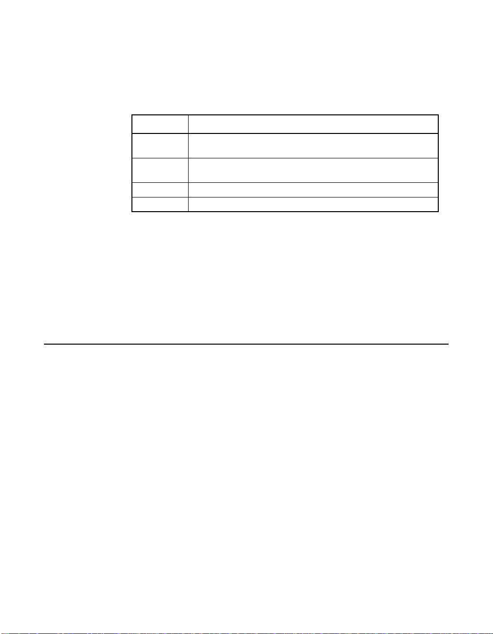
2.4.9 Disk Mirroring
With disk mirroring (used in RAID 1), data written to one disk is
simultaneously written to another disk. If one disk fails, the contents of the
other disk can be used to run the system and reconstruct the failed disk.
The primary advantage of disk mirroring is that it provides 100% data
redundancy. Because the disk contents are completely written to a second
disk, it does not matter whether one of the disks fails. Both disks contain
the same data at all times. Either drive can act as the operational drive.
Disk mirroring provides 100% redundancy, but is expensive because
each drive in the system must be duplicated. Figure 2.2 shows an
example of disk mirroring.
Figure 2.2 Disk Mirroring (RAID 1) Example
2.4.10 Parity
Segment 1
Segment 2
Segment 3
Segment 4 Segment 4 Duplicated
Segment 1 Duplicated
Segment 2 Duplicated
Segment 3 Duplicated
Parity generates a set of redundancy data from two or more parent data
sets. The redundancy data can reconstruct one of the parent data sets.
Parity data does not fully duplicate the parent data sets. In RAID, this
method is applied to entire drives or stripes across all disk drives in an
array. The types of parity are described in Table 2.1.
RAID Components and Features 2-7
Copyright © 2003–2006 by LSI Logic Corporation. All rights reserved.
Page 30
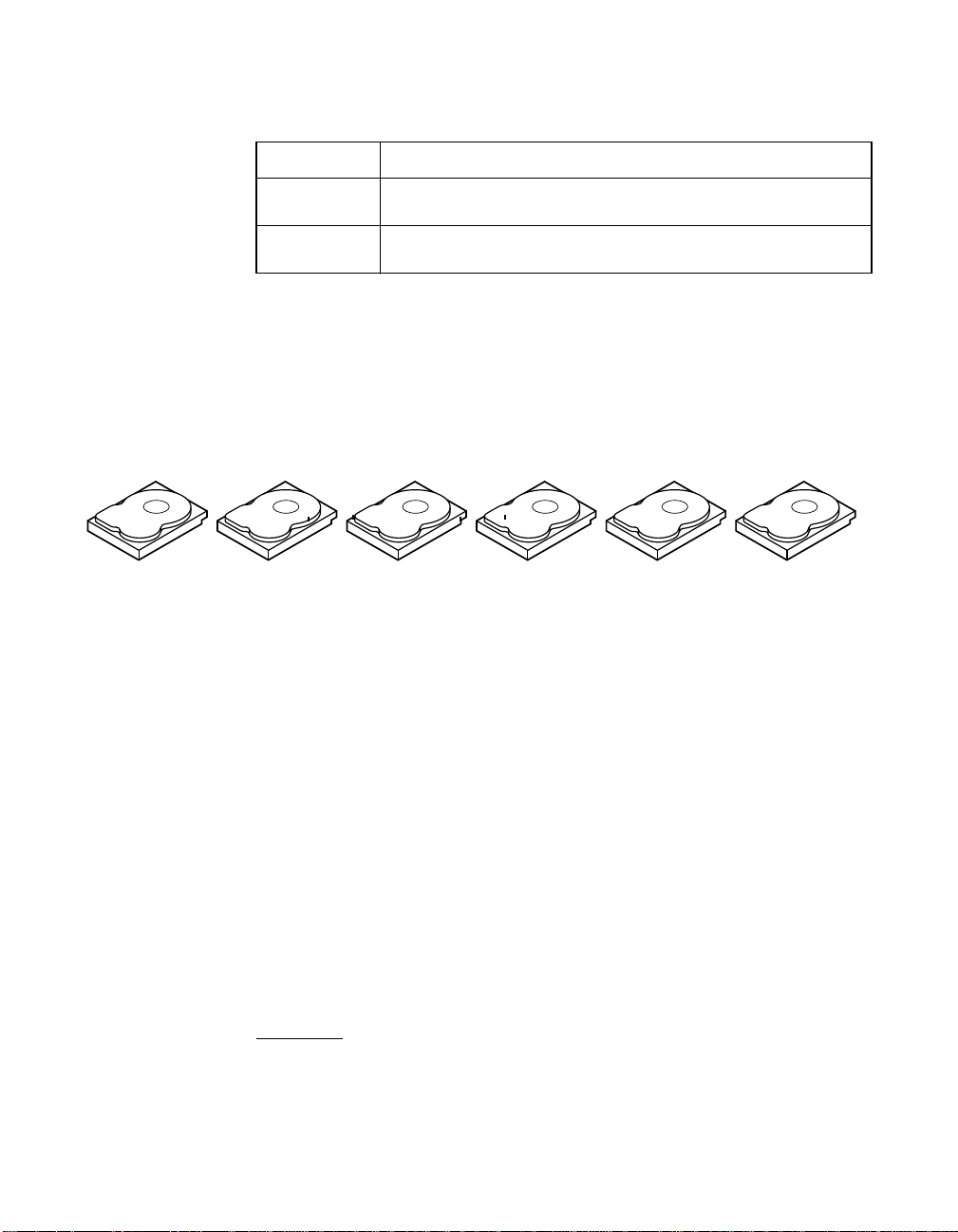
Table 2.1 Types of Parity
Parity Type Description
Dedicated The parity of the data on two or more disk drives is stored on
Distributed The parity data is distributed across more than one drive in the
an additional disk.
system.
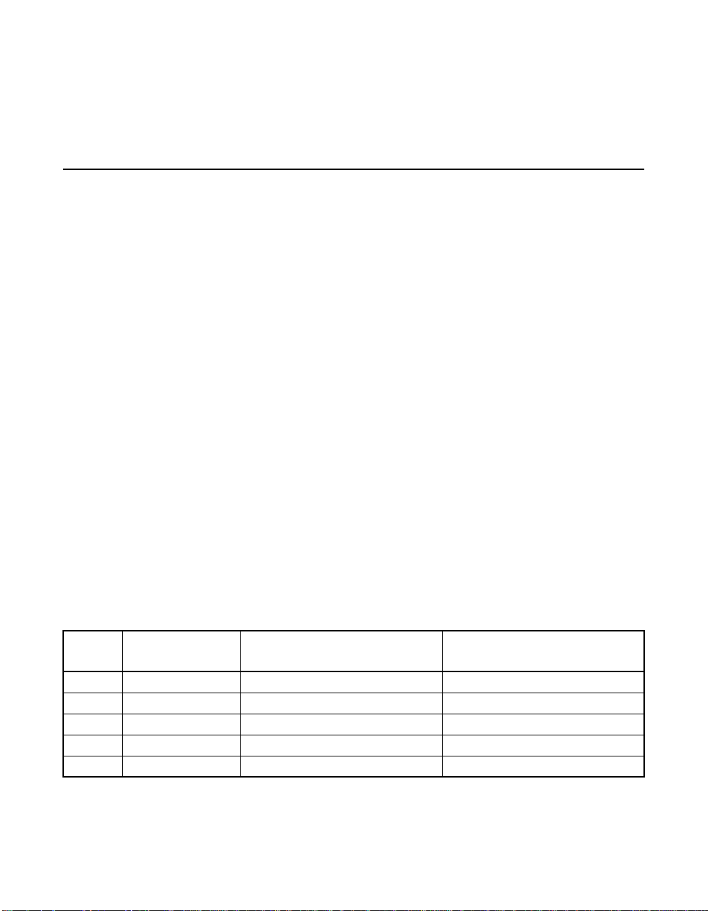
If a single disk drive fails, it can be rebuilt from the parity and the data
on the remaining drives. RAID level 5 combines distributed parity with
disk striping, as shown in Figure 2.3. Parity provides redundancy for one
drive failure without duplicating the contents of entire disk drives, but
parity generation can slow the write process.
Figure 2.3 Distributed Parity (RAID 5) Example
Segment 1
Segment 7
Parity (9–12)
Note: Parity is distributed across multiple drives in the array.
Segment 2
Segment 8
Segment 3
Segment 9
Parity (5–8)
Segment 4
Segment 10
2.4.11 Disk Spanning
Segment 5
Segment 11
Parity (1–4)
Segment 6
Segment 12
Disk spanning allows multiple physical drives to function like one big
drive. Disk spanning overcomes lack of disk space and simplifies storage
management by combining existing resources or adding relatively
inexpensive resources. For example, four 20 Gbyte drives can be
combined to appear to the operating system as a single 80 Gbyte drive.
Spanning alone does not provide reliability or performance
enhancements. Spanned logical drives must have the same stripe size
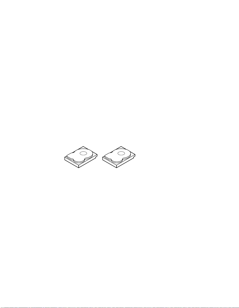
and must be contiguous. In Figure 2.4, RAID 1 arrays are turned into a
RAID 10 array.
Important: Make sure that the spans are in different backplanes, so
that if one span fails, you do not lose the whole array.
2-8 Introduction to RAID
Copyright © 2003–2006 by LSI Logic Corporation. All rights reserved.
Page 31

Figure 2.4 Disk Spanning (RAID 10) Example
60 Gbytes/s 60 Gbytes/s
Can Be Accessed as
One 120 Gbyte/s Drive
60 Gbytes/s 60 Gbytes/s
Can Be Accessed as
One 120 Gbyte/s Drive
Note: Spanning two contiguous RAID 0 logical drives does not
produce a new RAID level or add fault tolerance. It
increases the size of the logical volume and improves
performance by doubling the number of spindles.
Disk Spanning for RAID 10 or RAID 50. Table 2.2 describes how to
configure RAID 10 and RAID 50 by spanning. The logical drives must
have the same stripe size, and the maximum number of spans is eight.
The full drive size is used when you span logical drives; you cannot
specify a smaller drive size.
Table 2.2 Disk Spanning for RAID 10 and RAID 50
Level Description
10 Configure RAID 10 by spanning two contiguous RAID 1 logical drives.
50 Configure RAID 50 by spanning two contiguous RAID 5 logical drives.
The RAID 1 logical drives must have the same stripe size.
The RAID 5 logical drives must have the same stripe size.
2.4.12 Hot Spares
A hot spare is an extra, unused disk drive that is part of the disk
subsystem. It is usually in standby mode, ready for service if a drive fails.
Hot spares permit you to replace failed drives without system shutdown
or user intervention. MegaRAID 320 controllers can implement automatic
and transparent rebuilds of failed drives using hot spare drives, providing
a high degree of fault tolerance and zero downtime.
RAID Components and Features 2-9
Copyright © 2003–2006 by LSI Logic Corporation. All rights reserved.
Note. When running RAID 0 and RAID 5 logical drives on the
same set of physical drives (a sliced configuration), a
rebuild to a hot spare does not occur after a drive failure
until the RAID 0 logical drive is deleted.
Page 32

The RAID management software allows you to specify physical drives as
hot spares. When a hot spare is needed, the RAID controller assigns the
hot spare that has a capacity closest to and at least as great as that of
the failed drive to replace the failed drive. The failed drive is removed
from the logical drive and marked ready awaiting removal after the
rebuild to a hot spare begins. See Table 2.13 for detailed information
about the minimum and maximum number of physical drives supported
by each RAID level for each RAID controller. You can make hot spares
of the physical drives that are not in a RAID logical drive.
Note: If a rebuild to a hot spare fails for any reason, the hot spare
There are two types of hot spares:
• Global Hot Spare
• Dedicated Hot Spare
2.4.12.1 Global Hot Spare
A global hot spare can replace any failed drive in a redundant array as
long as its capacity is equal to or larger than the coerced capacity of the
failed drive. A global hot spare defined on any channel should be
available to replace a failed drive on both channels.
drive is marked as failed. If the source drive fails, both the
source drive and the hot spare drive are marked as failed.
2.4.12.2 Dedicated Hot Spare
A dedicated hot spare can replace a failed drive only in a selected array.
One or more drives can be designated as member of a spare drive pool;
the most suitable drive from the pool is selected for failover. A dedicated
hot spare is used before one from the global hot spare pool.
Hot spare drives can be located on any RAID channel. Standby hot
spares (not being used in RAID array) are polled every 60 seconds at a
minimum, and their status is made available in the array management
software. RAID controllers can rebuild with a disk that is in a system, but
not initially set to be a hot spare.
Observe the following parameters when using hot spares:
2-10 Introduction to RAID
Copyright © 2003–2006 by LSI Logic Corporation. All rights reserved.
Page 33

• Hot spares are used only in arrays with data redundancy, for
example, RAID levels 1, 5, 10, and 50.
• A hot spare connected to a specific RAID controller can rebuild a
drive that is connected to the same controller only.
• You must assign the hot spare to one or more drives through the
controller BIOS or use array management software to place it in the
hot spare pool.
• A hot spare must have free space equal to or greater than the drive
it would replace. For example, to replace an 18 Gbyte drive, the hot
spare must be 18 Gbytes or larger.
2.4.13 Disk Rebuilds
When a physical drive in a RAID array fails, you can rebuild the drive by
recreating the data that was stored on the drive before it failed. The RAID
controller uses hot spares to rebuild failed drives automatically and
transparently, at user-defined rebuild rates. If a hot spare is available, the
rebuild can start automatically when a drive fails. If a hot spare is not
available, the failed drive must be replaced with a new drive so the data
on the failed drive can be rebuilt. Rebuilding can be done only in arrays
with data redundancy, which includes RAID 1, 5, 10, and 50.
The failed physical drive is removed from the logical drive and marked
ready awaiting removal after the rebuild to a hot spare begins. If the
system goes down during a rebuild, the RAID controller automatically
restarts the rebuild after the system reboots.
Note: When the rebuild to a hot spare begins, the failed drive is
often removed from the logical drive before management
applications detect the failed drive. When this occurs, the
events logs show the drive rebuilding to the hot spare
without showing the failed drive. The formerly failed drive is
marked as ready after a rebuild begins to a hot spare.
Note: If a rebuild to a hot spare fails for any reason, the hot spare
drive is marked as failed. If the source drive fails, both the
source drive and the hot spare drive are marked as failed.
An automatic drive rebuild does not start if you replace a drive during an
online capacity expansion or RAID level migration. The rebuild must be
started manually after the expansion or migration procedure is complete.
RAID Components and Features 2-11
Copyright © 2003–2006 by LSI Logic Corporation. All rights reserved.
Page 34

2.4.13.1 Rebuild Rate
The rebuild rate is the percentage of the compute cycles dedicated to
rebuilding failed drives. A rebuild rate of 100 percent means the system
gives priority to rebuilding the failed drives.
The rebuild rate can be configured between 0 and 100 percent. At
0 percent, the rebuild is done only if the system is not doing anything
else. At 100 percent, the rebuild has a higher priority than any other
system activity. LSI recommends not using 0 or 100 percent. The default
rebuild rate is 30 percent.
2.4.13.2 Hot Swap
A hot swap is the manual replacement of a defective physical disk unit
while the computer is still running. When a new drive has been installed,
a rebuild occurs automatically if:
• The newly inserted drive is the same size as or larger than the
• The drive is placed in the same drive bay as the failed drive it
The RAID controller can be configured to detect the new disks and
rebuild the contents of the disk drive automatically.
failed drive
is replacing
2.4.14 SCSI Physical Drive States
The SCSI Physical drive states are described in Table 2.3.
Table 2.3 SCSI Physical Drive States
State Description
Online The physical drive is working normally and is a part of a
Ready The physical drive is functioning normally but is not part of a
Hot Spare The physical drive is powered up and ready for use as a spare in
Fail A fault has occurred in the physical drive, placing it out of service.
Rebuild The physical drive is being rebuilt with data from a failed drive.
2-12 Introduction to RAID
Copyright © 2003–2006 by LSI Logic Corporation. All rights reserved.
configured logical drive.
configured logical drive and is not designated as a hot spare.
case an online drive fails.
Page 35
2.4.15 Logical Drive States
The logical drive states are described in Table 2.4.
Table 2.4 Logical Drive States
State Description
Optimal The logical drive operating condition is good. All configured
Degraded The logical drive operating condition is not optimal. One of the
Failed The logical drive has failed.
Offline The logical drive is not available to the RAID controller.
physical drives are online.
configured physical drives has failed or is offline.
2.4.16 Enclosure Management
Enclosure management is the intelligent monitoring of the disk
subsystem by software and/or hardware. The disk subsystem can be part
of the host computer or can reside in an external disk enclosure.
Enclosure management helps you stay informed of events in the disk
subsystem, such as a drive or power supply failure. Enclosure
management increases the fault tolerance of the disk subsystem.
2.5 RAID Levels
The RAID controller supports RAID levels 0, 1, 5, 10, and 50. The
supported RAID levels are summarized in Section 2.5.1, “Summary of
RAID Levels.” In addition, it supports independent drives (configured as
RAID 0.) The following subsections describe the RAID levels in detail.
2.5.1 Summary of RAID Levels
RAID 0 uses striping to provide high data throughput, especially for large
files in an environment that does not require fault tolerance.
RAID 1 uses mirroring so that data written to one disk drive is
simultaneously written to another disk drive. This is good for small
databases or other applications that require small capacity, but complete
data redundancy.
RAID Levels 2-13
Copyright © 2003–2006 by LSI Logic Corporation. All rights reserved.
Page 36

RAID 5 uses disk striping and parity data across all drives
(distributed parity) to provide high data throughput, especially for small
random access.
RAID 10, a combination of RAID 0 and RAID 1, consists of striped data
across mirrored spans. It provides high data throughput and complete
data redundancy, but uses a larger number of spans.
RAID 50, a combination of RAID 0 and RAID 5, uses distributed parity
and disk striping and works best with data that requires high reliability,
high request rates, high data transfers, and medium-to-large capacity.
LSI does not recommend having RAID 0 and RAID 5 logical drives in the
same physical array. If a drive in the physical array has to be rebuilt, the
RAID 0 logical drive causes a failure during the rebuild.
2.5.2 Selecting a RAID Level
To ensure the best performance, you should select the optimal RAID
level when you create a system drive. The optimal RAID level for your
disk array depends on a number of factors:
• Number of physical drives in the disk array
• Capacity of the physical drives in the array
• Need for data redundancy
• Disk performance requirements
2.5.2.1 RAID 0
RAID 0 provides disk striping across all drives in the RAID array. RAID 0
does not provide any data redundancy, but does offer the best
performance of any RAID level. RAID 0 breaks up data into smaller
blocks and then writes a block to each drive in the array. The size of each
block is determined by the stripe size parameter, set during the creation
of the RAID set. RAID 0 offers high bandwidth.
Note: RAID level 0 is not fault-tolerant. If a drive in a RAID 0 array
fails, the whole logical drive (all physical drives associated
with the logical drive) fails.
2-14 Introduction to RAID
Copyright © 2003–2006 by LSI Logic Corporation. All rights reserved.
Page 37

By breaking up a large file into smaller blocks, the RAID controller can
use several drives to read or write the file faster. RAID 0 involves no
parity calculations to complicate the write operation. This makes RAID 0
ideal for applications that require high bandwidth but do not require fault
tolerance. RAID 0 also denotes an independent or single drive.
Table 2.5 provides an overview of RAID 0.
Table 2.5 RAID 0 Overview
Feature Description
2.5.2.2 RAID 1
Uses Provides high data throughput, especially for large files. Any
environment that does not require fault tolerance.
Strong Points Provides increased data throughput for large files. No
capacity loss penalty for parity.
Weak Points Does not provide fault tolerance or high bandwidth. All data
lost if any drive fails.
Drives 1 to (14 drives x the number of channels).
In RAID 1, the RAID controller duplicates all data from one drive to a
second drive. RAID 1 provides complete data redundancy, but at the cost
of doubling the required data storage capacity.
Table 2.6 provides an overview of RAID 1.
Table 2.6 RAID 1 Overview
Feature Description
Uses Appropriate for small databases or any other environment
that requires fault tolerance but small capacity.
Strong Points Provides complete data redundancy. RAID 1 is ideal for any
application that requires fault tolerance and minimal capacity.
Weak Points Requires twice as many disk drives. Performance is impaired
during drive rebuilds.
Drives 2
RAID Levels 2-15
Copyright © 2003–2006 by LSI Logic Corporation. All rights reserved.
Page 38

2.5.2.3 RAID 5
RAID 5 includes disk striping at the block level and parity. In RAID 5, the
parity information is written to several drives. RAID 5 is best suited for
networks that perform a lot of small input/output (I/O) transactions
simultaneously.
RAID 5 addresses the bottleneck issue for random I/O operations.
Because each drive contains both data and parity, numerous writes can
take place concurrently. In addition, robust caching algorithms and
hardware-based, exclusive-or assist make RAID 5 performance
exceptional in many different environments.
Table 2.7 provides an overview of RAID 5.
Table 2.7 RAID 5 Overview
Feature Description
2.5.2.4 RAID 10
Uses Provides high data throughput, especially for large files. Use
RAID 5 for transaction processing applications because
each drive can read and write independently. If a drive fails,
the RAID controller uses the parity drive to recreate all
missing information. Use also for office automation and
online customer service that requires fault tolerance. Use for
any application that has high read request rates but low write
request rates.
Strong Points Provides data redundancy, high read rates, and good
performance in most environments. Provides data
redundancy with lowest loss of capacity.
Weak Points Not well-suited to tasks requiring numerous writes. Suffers
more impact if no cache is used (clustering). Disk drive
performance is reduced if a drive is being rebuilt.
Environments with few processes do not perform as well
because the RAID overhead is not offset by the performance
gains in handling simultaneous processes.
Drives 3 to (14 drives x the number of channels).
RAID 10 is a combination of RAID 0 and RAID 1. RAID 10 consists of
striped data across mirrored spans. RAID 10 breaks up data into smaller
blocks, then mirrors the blocks of data to each RAID 1 set. Each RAID 1
set then duplicates its data to its other drive. The size of each block is
determined by the stripe size parameter, which is set during the creation
of the RAID set. Up to 8 spans can be supported by RAID 10.
2-16 Introduction to RAID
Copyright © 2003–2006 by LSI Logic Corporation. All rights reserved.
Page 39

Table 2.8 provides an overview of RAID 10.
Table 2.8 RAID 10 Overview
Feature Description
Uses Appropriate when used with data storage that needs 100%
redundancy of mirrored arrays and that also needs the
enhanced I/O performance of RAID 0 (striped arrays.) RAID
10 works well for medium-sized databases or any
environment that requires a higher degree of fault tolerance
and moderate to medium capacity.
Strong Points Provides both high data transfer rates and complete data
redundancy.
Weak Points Requires twice as many drives as all other RAID levels
except RAID 1.
Drives 2n, where n is greater than 1.
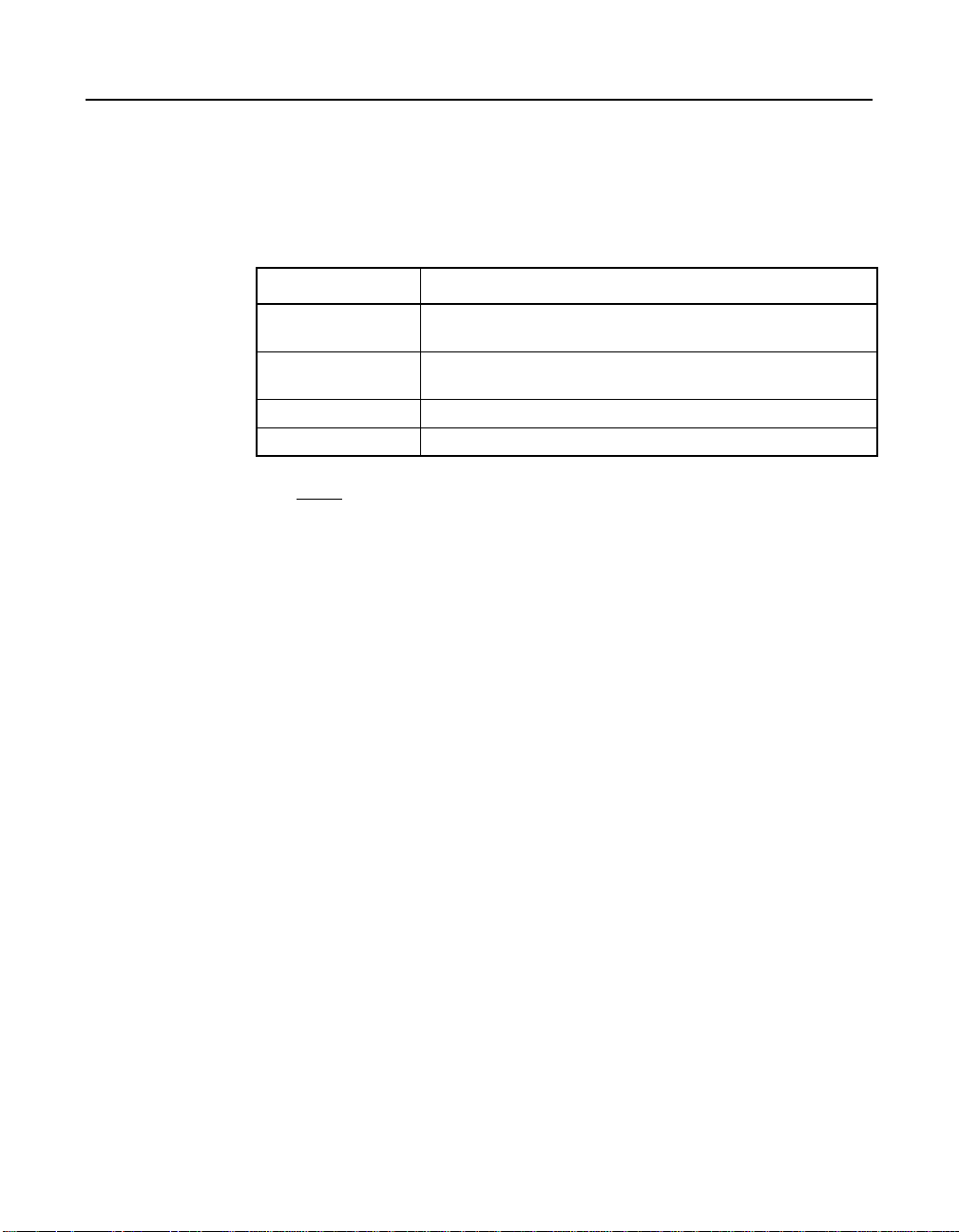
In Figure 2.5, logical drive 0 is created by distributing data across four
arrays (arrays 0 through 3). Spanning is used because one logical drive
is defined across more than one array. Logical drives defined across
multiple RAID 1 level arrays are referred to as RAID 10 logical drives. To
increase performance, data is striped across arrays, which enables
access to multiple arrays simultaneously.
Using RAID level 10, rather than a simple RAID set, up to 8 spans can
be supported, and up to 8 drive failures can be tolerated, though less
than total disk drive capacity is available. Though multiple drive failures
can be tolerated, only one drive failure can be tolerated in each RAID 1
level array.
Figure 2.5 RAID 10 Logical Drive
RAID 10
Segment 1 Segment 1
Segment 5
...
Duplicate
Segment 5
Duplicate
RAID 1 RAID 1 RAID 1 RAID 1
RAID Levels 2-17
Copyright © 2003–2006 by LSI Logic Corporation. All rights reserved.
Segment 2 Segment 3
Segment 6
... ... ...
Segment 2
Duplicate
Segment 6
Duplicate
Segment 3 Segment 4
Segment 7
RAID 0
Duplicate
Segment 7
Duplicate
Segment 8
Segment 4
Duplicate
Segment 8
Duplicate
Page 40

2.5.2.5 RAID 50
RAID 50 provides the features of both RAID 0 and RAID 5. RAID 50
includes both distributed parity and disk striping across multiple arrays.
RAID 50 is best implemented on two RAID 5 disk arrays with data striped
across both disk arrays.
RAID 50 breaks up data into smaller blocks, then stripes the blocks of
data to each RAID 5 disk set. RAID 5 breaks up data into smaller blocks,
calculates parity by performing an exclusive-or on the blocks, then writes
the blocks of data and parity to each drive in the array. The size of each
block is determined by the stripe size parameter, which is set during the
creation of the RAID set.
RAID 50 can support up to 8 spans and tolerate up to 8 drive failures,
though less than total disk drive capacity is available. Though multiple
drive failures can be tolerated, only one drive failure can be tolerated in
each RAID 1 level array.
Table 2.9 provides an overview of RAID 50.
Table 2.9 RAID 50 Overview
Feature Description
Uses Appropriate when used with data that requires high
Strong Points Provides high data throughput, data redundancy and very
Weak Points Requires 2 to 8 times as many parity drives as RAID 5.
Drives 6 to (14 drives x the number of channels)
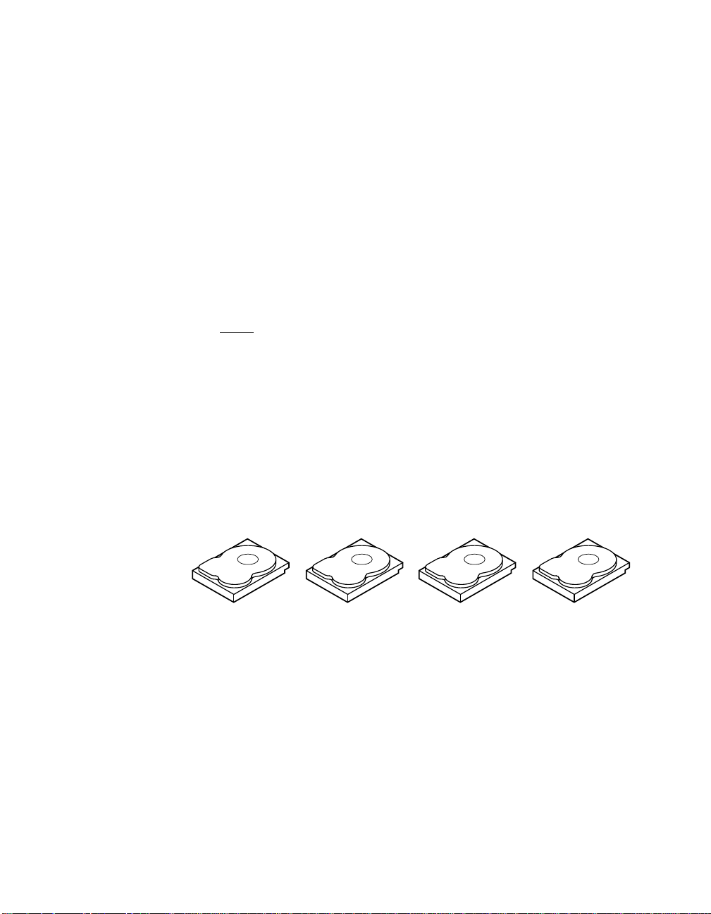
Figure 2.6 provides an example of a RAID 50 level logical drive.
2-18 Introduction to RAID
Copyright © 2003–2006 by LSI Logic Corporation. All rights reserved.
reliability, high request rates, high data transfer, and medium
to large capacity.
good performance.
Page 41

Figure 2.6 RAID 50 Logical Drive
RAID 50
Segment 1
Segment 6
(Segment 9, 10)
Segment 2
(Segment 5, 6)
Segment 9
RAID 5 RAID 5
(Segment 1, 2)
Segment 5
Segment 10
(Segment 11, 12)
RAID 0
2.6 RAID Configuration Strategies
The most important factors in RAID array configuration are:
• Logical drive availability (fault tolerance)
• Logical drive performance
• Logical drive capacity
You cannot configure a logical drive that optimizes all three factors, but
it is easy to choose a logical drive configuration that maximizes one
factor at the expense of another factor. For example, RAID 1 (mirroring)
provides excellent fault tolerance, but requires a redundant drive. The
following subsections describe how to use the RAID levels to maximize
logical drive availability (fault tolerance), logical drive performance, and
logical drive capacity.
Segment 3
Segment 8
Segment 4
(Segment 7, 8)
Segment 11
(Segment 3, 4)
Segment 7
Segment 12
2.6.1 Maximizing Fault Tolerance
Fault tolerance is achieved through the ability to perform automatic and
transparent rebuilds using hot spare drives and hot swaps. A hot spare
drive is an available, unused online drive that the RAID controller
instantly plugs into the system when an active drive fails. After the hot
spare is automatically moved into the RAID array, the failed drive is
automatically rebuilt on the spare drive. The RAID array continues to
handle requests while the rebuild occurs.
RAID Configuration Strategies 2-19
Copyright © 2003–2006 by LSI Logic Corporation. All rights reserved.
Page 42

A hot swap is the manual substitution of a replacement unit in a disk
subsystem for a defective one, where the substitution can be performed
while the subsystem is running hot swap drives. Auto-Rebuild in the
BIOS Configuration Utility allows a failed drive to be replaced and
automatically rebuilt by hot-swapping the drive in the same drive bay. The
RAID array continues to handle requests while the rebuild occurs,
providing a high degree of fault tolerance and zero downtime. Table 2.10
describes the fault tolerance features of each RAID level.
Table 2.10 RAID Levels and Fault Tolerance
RAID
Level Fault Tolerance
0 Does not provide fault tolerance. All data lost if any drive fails. Disk striping writes data across
1 Provides complete data redundancy. If one disk drive fails, the contents of the other disk drive
5 Combines distributed parity with disk striping. Parity provides redundancy for one drive failure
10 Provides complete data redundancy using striping across spanned RAID 1 arrays. RAID 10
50 Provides data redundancy using distributed parity across spanned RAID 5 arrays. RAID 50
multiple disk drives instead of just one disk drive. It involves partitioning each drive storage
space into stripes that can vary in size. RAID 0 is ideal for applications that require high
bandwidth but do not require fault tolerance.
can run the system and reconstruct the failed drive. The primary advantage of disk mirroring is
that it provides 100% data redundancy.Since the contents of the disk drive are completely written
to a second drive, no data is lost if one of the drives fails. Both drives contain the same data at
all times. RAID 1 is ideal for any application that requires fault tolerance and minimal capacity.
without duplicating the contents of entire disk drives. If a drive fails, the RAID controller uses
the parity data to rebuild all missing information. In RAID 5, this method is applied to entire
drives or stripes across all disk drives in an array. Using distributed parity, RAID 5 offers fault
tolerance with limited overhead.
works well for any environment that requires the 100 percent redundancy offered by mirrored
arrays. RAID 10 can sustain a drive failure in each mirrored array and maintain drive integrity.
includes both parity and disk striping across multiple drives. If a drive fails, the RAID controller
uses the parity data to recreate all missing information. RAID 50 can sustain one drive failure
per RAID 5 array and still maintain data integrity.
2-20 Introduction to RAID
Copyright © 2003–2006 by LSI Logic Corporation. All rights reserved.
Page 43

2.6.2 Maximizing Performance
A RAID disk subsystem improves I/O performance. The RAID array
appears to the host computer as a single storage unit or as multiple
logical units. I/O is faster because drives can be accessed simultaneously.
Table 2.11 describes the performance for each RAID level.
Table 2.11 RAID Levels and Performance
RAID
Level Performance
0 RAID 0 (disk striping) offers the best performance of any RAID level. RAID 0 breaks up data
1 With RAID 1 (disk mirroring), each drive in the system must be duplicated, which requires
5 RAID 5 (distributed parity) provides high data throughput, especially for large files. Use this
10 RAID 10 (disk spanning) works best for data storage that needs the enhanced I/O
50 RAID 50 (disk spanning) works best when used with data that requires high reliability, high
into smaller blocks, then writes a block to each drive in the array. Disk striping writes data
across multiple disk drives instead of just one disk drive. It involves partitioning each drive
storage space into stripes that can vary in size from 8 Kbytes to 128 Kbytes. These stripes
are interleaved in a repeated sequential manner. Disk striping enhances performance
because multiple drives are accessed simultaneously.
more time and resources than striping. Performance is impaired during drive rebuilds.
RAID level for any application that requires high read request rates, but low write request
rates, such as transaction processing applications, because each drive can read and write
independently. Since each drive contains both data and parity, numerous writes can take
place concurrently. In addition, robust caching algorithms and hardware based exclusive-or
assist make RAID 5 performance exceptional in many different environments.
Parity generation can slow the write process, making write performance significantly lower for
RAID 5 than for RAID 0 or RAID 1. Disk drive performance is reduced if a drive is being
rebuilt. Clustering can also reduce drive performance. Environments with few processes do
not perform as well because the RAID overhead is not offset by the performance gains in
handling simultaneous processes.
performance of RAID 0 (striped arrays), which provides high data transfer rates. Spanning
increases the size of the logical volume and improves performance by doubling the number
of spindles. The system performance improves as the number of spans increases.
(The maximum number of spans is eight.) As the storage space in the spans is filled, the
system stripes data over fewer and fewer spans and RAID performance degrades to that of
a RAID 1 or RAID 5 array.
request rates, and high data transfer. It provides high data throughput, data redundancy, and
very good performance. Spanning increases the size of the logical volume and improves
performance by doubling the number of spindles. The system performance improves as the
number of spans increases. (The maximum number of spans is eight.) As the storage space
in the spans is filled, the system stripes data over fewer and fewer spans and RAID
performance degrades to that of a RAID 1 or RAID 5 array.
RAID Configuration Strategies 2-21
Copyright © 2003–2006 by LSI Logic Corporation. All rights reserved.
Page 44

2.6.3 Maximizing Storage Capacity
Storage capacity is an important factor when selecting a RAID level.
There are several variables to consider. Mirrored data and parity data
require more storage space than striping alone (RAID 0). Parity
generation uses algorithms to create redundancy and requires less
space than mirroring. Table 2.12 explains the effects of the RAID levels
on storage capacity.
Table 2.12 RAID Levels and Capacity
RAID
Level Capacity
0 RAID 0 (disk striping) involves partitioning each drive storage space into stripes that can vary
1 With RAID 1 (disk mirroring), data written to one disk drive is simultaneously written to
5 RAID 5 (distributed parity) provides redundancy for one drive failure without duplicating the
10 RAID 10 (disk spanning) requires twice as many drives as all other RAID levels except RAID
50 RAID 50 (disk spanning) requires two to four times as many parity drives as RAID 5. This
in size. The combined storage space is composed of stripes from each drive.RAID 0 provides
maximum storage capacity for a given set of physical disks.
another disk drive, which doubles the required data storage capacity. This is expensive
because each drive in the system must be duplicated.
contents of entire disk drives. RAID 5 breaks up data into smaller blocks, calculates parity by
performing an exclusive-or on the blocks, then writes the blocks of data and parity to each
drive in the array. The size of each block is determined by the stripe size parameter, which
is set during the creation of the RAID set.
1. RAID 10 works well for medium-sized databases or any environment that requires a higher
degree of fault tolerance and moderate to medium capacity. Disk spanning allows multiple
disk drives to function like one big drive. Spanning overcomes lack of disk space and
simplifies storage management by combining existing resources or adding relatively
inexpensive resources.
RAID level works best when used with data that requires medium to large capacity.
2-22 Introduction to RAID
Copyright © 2003–2006 by LSI Logic Corporation. All rights reserved.
Page 45

2.7 RAID Availability
Data availability without downtime is essential for many types of data
processing and storage systems. Businesses want to avoid the financial
costs and customer frustration associated with downed servers. RAID
helps you maintain data availability and avoid downtime for the servers
that provide that data. RAID offers several features, such as spare drives
and rebuilds, that you can use to fix any hard drive problems, while
keeping the server(s) running and data available. The following
subsections describe these features.
2.7.1 Spare Drives
You can use spare drives to replace failed or defective drives in an array.
A replacement drive must be at least as large as the drive it replaces.
Spare drives include hot swaps, hot spares, and cold swaps.
A hot swap is the manual substitution of a replacement unit in a disk
subsystem for a defective one, where the substitution can be performed
while the subsystem is running (performing its normal functions). The
backplane and enclosure must support hot swap in order for the
functionality to work.
Hot spare drives are physical drives that power up along with the RAID
drives and operate in a standby state. If a hard drive used in a RAID
logical drive fails, a hot spare automatically takes its place and the data
on the failed drive is rebuilt on the hot spare. Hot spares can be used for
RAID levels 1, 5, 10, and 50.
A cold swap requires that you power down the system before replacing
a defective hard drive in a disk subsystem.
2.7.2 Rebuilding
If a hard drive fails in an array that is configured as a RAID 1, 5, 10, or
50 logical drive, you can recover the lost data by rebuilding the drive. If
you have configured hot spares, the RAID controller automatically tries
RAID Availability 2-23
Copyright © 2003–2006 by LSI Logic Corporation. All rights reserved.
Note: If a rebuild to a hot spare fails for any reason, the hot spare
drive is marked as failed. If the source drive fails, both the
source drive and the hot spare drive are marked as failed.
Page 46
to use them to rebuild failed disks. Manual rebuild is necessary if no hot
spares with enough capacity to rebuild the failed drives are available.You
must insert a drive with enough storage into the subsystem before
rebuilding the failed drive.
2.8 RAID Configuration Planning
Factors to consider when planning a configuration are the number of
hard disk drives the RAID controller can support, the purpose of the
array, and the availability of spare drives.
Each type of data stored in the disk subsystem has a different frequency
of read and write activity. If you know the data access requirements, you
can more successfully determine a strategy for optimizing the disk
subsystem capacity, availability, and performance.
Servers that support video on demand typically read the data often, but
write data infrequently. Both the read and write operations tend to be
long. Data stored on a general-purpose file server involves relatively
short read and write operations with relatively small files.
2.8.1 Number of Physical Disk Drives
Your configuration planning depends in part on the number of physical
disk drives that you want to use in a RAID array. The number of drives
in an array determines the RAID levels that can be supported. Only one
RAID level can be assigned to each logical drive. Table 2.13 shows the
minimum and maximum number of drives required for each RAID level.
Table 2.13 Physical Drives Required for Each RAID Level
RAID
Level
0 1 14 28
1 2 2 2
5 3 14 28
10 4 14 28
50 6 14 28
2-24 Introduction to RAID
Minimum # of
Physical Drives
Copyright © 2003–2006 by LSI Logic Corporation. All rights reserved.
Maximum # of Physical Drives
for Single-Channel Controller
Maximum # of Physical Drives
for Dual-Channel Controller
Page 47

2.8.2 Array Purpose
Important factors to consider when creating RAID arrays include
availability, performance, and capacity. Define the major purpose of the
disk array by answering questions related to these factors, such as the
following,which are followed by suggested RAID levels for each situation:
• Does this disk array increase the system storage capacity for
general-purpose file and print servers? Use RAID 5, 10, or 50.
• Does this disk array support any software system that must be
available 24 hours per day? Use RAID 1, 5, 10, or 50.
• Does the information stored in this disk array contain large audio or
video files that must be available on demand? Use RAID 0.
• Does this disk array contain data from an imaging system? Use
RAID 0 or 10.
Fill out Table 2.14 to help you plan the array configuration. Rank the
requirements for your array, such as storage space and data redundancy,
in order of importance, then review the suggested RAID levels.
Table 2.14 Factors to Consider for Array Configuration
Requirement Rank Suggested RAID Level(s)
Storage space RAID 0, RAID 5
Data redundancy RAID 5, RAID 10, RAID 50
Hard drive performance and throughput RAID 0, RAID 10
Hot spares (extra hard drives required) RAID 1, RAID 5, RAID 10, RAID 50
RAID Configuration Planning 2-25
Copyright © 2003–2006 by LSI Logic Corporation. All rights reserved.
Page 48

2-26 Introduction to RAID
Copyright © 2003–2006 by LSI Logic Corporation. All rights reserved.
Page 49

Chapter 3
BIOS Configuration
Utility and
MegaRAID Manager
The MegaRAID BIOS Configuration Utility (CU) configures disk arrays
and logical drives. Because the CU resides in the BIOS, it is independent
of the operating system.
MegaRAID Manager is a character-based, non-GUI utility that changes
policies, and parameters, and monitors RAID systems.
MegaRAID Manager runs under the DOS, Red Hat Linux, and NetWare
operating systems.
The BIOS Configuration Utility and MegaRAID Manager use the same
command structure to configure controllers and disks. The following
sections describe the steps to start either utility and detailed instructions
to perform configuration steps using either utility.
Note: MegaRAID Manager screens differ slightly from the BIOS
Configuration Utility screens, but the utilities have
similar functions.
Use the configuration utilities to do the following:
• Select a configuration method for physical arrays and logical disks
• Create physical arrays
• Define logical drives
• Initialize logical drives
• Access controllers, logical drives, and physical arrays to display their
properties
• Create hot spare drives
• Verify that the redundancy data in logical drives using RAID level
1, 5, 10, or 50 is correct
• Rebuild failed drives
MegaRAID Configuration Software User’s Guide 3-1
Version 2.0 Copyright © 2003–2006 by LSI Logic Corporation. All rights reserved.
Page 50

• Reconstruct logical drives after changing RAID levels or adding a
hard drive to an array
• Select a MegaRAID host adapter
This chapter consists of the following sections:
• Section 3.1, “Quick Configuration Steps for the BIOS
Configuration Utility”
• Section 3.2, “Quick Configuration Steps for MegaRAID Manager”
• Section 3.3, “Configuration Utility Menu”
• Section 3.4, “Detailed Configuration Instructions”
• Section 3.5, “Deleting Logical Drives”
• Section 3.6, “Performing Drive Roaming”
• Section 3.7, “Performing Drive Migration”
• Section 3.8, “Rebuilding Failed Disks”
• Section 3.9, “FlexRAID Virtual Sizing,”
• Section 3.10, “Checking Data Consistency”
• Section 3.11, “Reconstructing Logical Drives”
• Section 3.12, “Replacing a Failed Controller Containing Data in
the TBBU”
• Section 3.13, “Using a Preloaded System Drive”
• Section 3.14, “Exiting MegaRAID Configuration Utility”
3.1 Quick Configuration Steps for the BIOS Configuration Utility
This section provides quick installation steps for users who are familiar
with the MegaRAID utilities and tools. Refer to Section 3.4, “Detailed
Configuration Instructions,” on page 3-16 for detailed configuration
instructions. To configure arrays and logical drives using the
MegaRAID CU:
Step 1. Boot the system.
Step 2. Start the MegaRAID CU by pressing CTRL+M.
3-2 BIOS Configuration Utility and MegaRAID Manager
Version 2.0 Copyright © 2003–2006 by LSI Logic Corporation. All rights reserved.
Page 51

Note: If the configuration utility does not display, go into BIOS
setup and disable Quick boot, Fast boot, Silent boot,
Intel Rapid boot, and Quick POST, then reboot. If you are
still unable to access the configuration utility, check for a
system BIOS upgrade or use Megaconf.exe.
Step 3. Select a configuration method.
Step 4. Designate hot spare disks (optional).
Step 5. Create arrays using the available physical drives.
Step 6. Define the logical drive(s) using the space in the arrays.
Step 7. Initialize the new logical drive(s).
3.2 Quick Configuration Steps for MegaRAID Manager
This section provides quick installation steps for users who are familiar
with the MegaRAID utilities and tools. See Section 3.4.4, “Configuring
Arrays and Logical Drives,” on page 3-18 for detailed configuration
instructions.
The steps to configure arrays and logical drives with the MegaRAID
CU are:
Step 1. Boot the system to DOS, Red Hat Linux, or NetWare.
Step 2. Start the MegaRAID Manager.
Step 3. Select a configuration method.
Step 4. Designate hot spares (optional).
Step 5. Create arrays using the available physical drives.
Step 6. Define the logical drive(s) using the space in the arrays.
Step 7. Initialize the logical drives.
Quick Configuration Steps for MegaRAID Manager 3-3
Version 2.0 Copyright © 2003–2006 by LSI Logic Corporation. All rights reserved.
Page 52

3.3 Configuration Utility Menu
Figure 3.1 shows the menu tree for the BIOS Configuration Utility and
MegaRAID Manager. The following sections describe each menu item.
Figure 3.1 MegaRAID Configuration Utility Menu Tree
Configure
(Section 3.3.1)
Initialize
Objects
(Section 3.3.3)
(Section 3.3.2)
Clear
(Section 3.3.4)
Rebuild
Check Consistency
Reconstruct
Select Adapter
(Section 3.3.5)
Easy Configuration
New Configuration
View/Add Configuration
Clear Configuration
Specify Boot Drive
Adapter
Logical Drive
Physical Drive
Channel
Battery Information
Reset Battery
(Section 3.3.6)
(Section 3.3.7)
(Section 3.3.8)
Clear Configuration
FlexRAID PowerFail
Fast Initialization
Disk Spin Up Timings
Cache Flush Timings
Rebuild Rate
Other Adapter Information
Factory Default
Disable BIOS
Emulation
Auto Rebuild
Initiator ID
Boot Time BIOS Options
Patrol ReadOptions
Patrol Read Mode
Patrol Read Status
Patrol Read Control
Initialize
Check Consistency
View/Update Parameters
Rebuild
Clear
Force Online
Force Offline/Remove HSP
Make Hot Spare
View Drive Information
View Rebuild Progress
SCSI Command Qtagging
Transfer Speed Option
Channels
Charge Counter
Backup Module
Battery Pack
Temperature
Voltage
Fast Charging
No of Cycles
BIOS Stops on Error
BIOS Echoes Message
BIOS Configuration Autoselection
RAID
Size
StripeSize
Write Policy
Read Policy
Cache Policy
#Stripes
Drive State
Termination State
SCSI Transfer Rate
3-4 BIOS Configuration Utility and MegaRAID Manager
Version 2.0 Copyright © 2003–2006 by LSI Logic Corporation. All rights reserved.
Page 53

3.3.1 Configure Menu
Select this option to configure physical arrays and logical drives. This
section describes the options of the Configure menu.
Configuration Menu Options – The Configure menu provides four
methods to modify and/or create logical disk configuration:
Easy Configuration, New Configuration, View/Add Configuration, and
Clear Configuration. Table 3.1 provides an overview of these methods.
The configuration menu has an Advance Menu that enables you to set
specific options. The available options depend upon the configuration
method you use.
To store the configuration information, the CU reserves 32 bytes on a
disk when a hard drive is configured.
Table 3.1 Configuration Utility Configure Menu
Option Description
Easy
Configuration
New
Configuration
View/Add
Configuration
Clear
Configuration
Specify Boot
Drive
Easy Configuration automatically associates every physical array with one logical drive.
Through the Advance Menu, Easy Configuration allows you to modify the RAID level,
stripe size, cache write policy, read policy, and I/O policy. Section 3.4.7.2, “Easy
Configuration,” on page 3-22 provides detailed instructions.
New Configuration allows you to modify the RAID level, stripe size, cache write policy,
read policy, I/O policy, logical drive size, and array spanning (associating logical drives
with multiple arrays). If you select New Configuration, the CU deletes the existing
configuration information on the selected controller when saving the new configuration.
Section 3.4.7.3, “New Configuration and View/Add Configuration,” on page 3-24
provides detailed instructions.
View/Add Configuration allows you to control the same logical drive parameters as
New Configuration without disturbing the existing configuration information. The View/Add
configuration also allows you to enable the Configuration on Disk feature.Section 3.4.7.3,
“New Configuration and View/Add Configuration,” provides detailed instructions.
This option erases the current configuration information.
This option enables you to specify a logical drive as the boot drive on the adapter. This
displays if you have created logical drives.
Configuration Utility Menu 3-5
Version 2.0 Copyright © 2003–2006 by LSI Logic Corporation. All rights reserved.
Page 54

3.3.2 Initialize Option
This option initializes one or more logical drives, which prepares them for
use. Initialize each new logical drive you configure. Section 3.4.8,
“Initializing Logical Drives,” on page 3-26 describes how to initialize drives.
Warning: Initializing a logical drive destroys all data on the logical drive.
3.3.3 Objects Menu
Select Objects from the Configuration Utility main menu to view or
change settings for the controller, logical drives, physical drives, and
channels. Table 3.2 lists and describes the Objects menu options.
Table 3.2 Configuration Utility Objects Menu
Menu Item Description
Adapter Use this option to configure the adapter properties. Section 3.3.3.1, “Adapter
Logical Drive Use this option to perform tasks on the logical drives. Section 3.3.3.4, “Logical
Physical Drive Use this option to perform tasks on the physical drives. Section 3.3.3.5, “Physical
Channel Use this option to configure channel-related or port-related properties.
Battery
Information
Reset Battery
Charge Counter
1. If the battery is not present on the board, this option does not display.
1
Submenu Description,” on page 3-6 provides more information.
Drive Submenu Description,” on page 3-10 provides more information.
Drive Submenu Description,” on page 3-12 provides more information.
Section 3.3.3.6, “Channel Submenu Description,” on page 3-13 provides
more information.
Use this option to display and configure the battery backup on your system, if your
system supports the battery backup feature. Section 3.3.3.7, “Battery Backup
Submenu Description,” on page 3-14 provides more information.
Use this option to reset the battery charge counter.
1
3.3.3.1 Adapter Submenu Description
The Adapter submenu allows you to select a MegaRAID controller if your
computer has multiple controllers. In addition, this submenu allows you
to modify the parameters for the selected controller. Select Adapter from
the Objects menu to select a controller and modify its parameters.
Table 3.3 provides Adapter submenu options.
3-6 BIOS Configuration Utility and MegaRAID Manager
Version 2.0 Copyright © 2003–2006 by LSI Logic Corporation. All rights reserved.
Page 55

Table 3.3 Configuration Utility Adapter Submenu
Option Description
Clear Configuration This option erases the current RAID configuration in the NVRAM.
FlexRAID PowerFail Use this option to enable the FlexRAID®PowerFail feature, which allows drive
Fast Initialization Use this option to initialize the logical drive by writing zeros to the first sector of
Disk Spin up Timings Use this option to configure the timing for spinning up the hard disk drives. The
Cache Flush Timings Use this option to set the cache flush interval to 2, 4, 6, 8, or 10 seconds.
Rebuild Rate Use this option to change the drive rebuild rate. The rebuild rate is the
Other Adapter
Information
Factory Default Use this option to load the default MegaRAID Configuration Utility settings.
Disable BIOS Use this option to disable the BIOS.
Emulation Use this option to select the I2C or mass storage mode. The default is mass
Auto Rebuild Use this option to enable automatic drive rebuilds after a drive failure. The failed
Initiator ID Use this option to set the initiator ID for the adapter. The default is 7.
Boot Time BIOS
Options
reconstruction to continue when the system restarts after a power failure.
the logical drive. The fast initialization completes in 3 seconds.
When this option is set to Disabled, a full initialization takes place on the entire
logical drive. On a larger array (over five drives), LSI recommends setting fast
initialization to Disabled, then initializing. Otherwise, the controller runs a
background consistency check within 5 minutes of reboot or RAID 5 creation.
options are Automatic, 2 disks every 6 secs, 4 disks every 6 secs, and
6 disks every 6 secs.
percentage of system resources dedicated to rebuilding a failed drive. A rebuild
rate of 100 percent means the system is totally dedicated to rebuilding the failed
drive. The default is 30 percent.
Use this option to display general information about the adapter, such as the
adapter type, firmware version, BIOS version, and DRAM size.
storage mode.
drive is rebuilt with data from another drive or drives.
The following are options you can select for events that occur during bootup,
such as BIOS error or messages.
• BIOS Stops on Error: Select this option to have the system BIOS stop during
bootup if there are BIOS errors. This gives you the option to enter the
configuration utility to resolve the problem.
• BIOS Echoes Messages: When set to On (the default), all controller BIOS
messages display during bootup.
• BIOS Configuration Autoselection: Use this option if there is a mismatch
between configuration data in the hard disk drives and NVRAM, so you can
select a method to resolve it. The options are Disk and User. The default
is User.
Configuration Utility Menu 3-7
Version 2.0 Copyright © 2003–2006 by LSI Logic Corporation. All rights reserved.
Page 56

Table 3.3 Configuration Utility Adapter Submenu (Cont.)
Option Description
Patrol Read Options The Patrol Read function is designed as a preventive measure that includes
review of your system for possible physical disk errors that could lead to physical
disk failure and damage data integrity. The Patrol Read operation can find and
possibly resolve any potential problem with physical disks prior to host access.
This can enhance overall system performance because error recovery during a
normal I/O operation may not be necessary.
• Patrol Read Mode: The Patrol Read mode can be set to Auto or Manual
mode. In Auto mode, Patrol Read runs continuously on the system and is
scheduled to start a new Patrol Read within four hours after the last iteration
is completed.
• Patrol Read Status: Displays the number of iterations completed, the current
state of the patrol read (active or stopped), and the schedule for the next
execution of patrol read.
• Patrol Read Control: If you use Manual mode, select Patrol Read Control to
initiate a Patrol Read. Press ENTER, then select Start and press ENTER again.
3.3.3.2 Port Multiplier
The port multiplier is a mechanism that connects a MegaRAID SATA
controller to up to four hard drives per port. This allows you to connect
more devices, driving down the cost per port. For example, with the SATA
300-8X Controller, which has eight ports, you can connect up to 32
devices using eight, 1-to-4 port multipliers.
In the BIOS Configuration Utility, the default for the Port Multiplier option
is Disabled. You can access this option and select Enabled in order to
use the port multipliers. When you enable the Port Multiplier option, it
becomes effective after you reboot. When you reboot, the BIOS banner
displays either PM-ENBL or PM-DSBL to indicate whether the Port Multiplier
option is enabled or disabled.
You can change the setting for this option only if no logical drives are
configured. If you attempt to change the setting and if there are any
logical drives present, a message displays to state that this is not
allowed, as shown in Figure 3.2.
3-8 BIOS Configuration Utility and MegaRAID Manager
Version 2.0 Copyright © 2003–2006 by LSI Logic Corporation. All rights reserved.
Page 57

Figure 3.2 Port Multiplier Option
The BIOS Configuration Utility displays the port and physical drive
information in a matrix format. This format displays the port number and
ID numbers for the hard drives connected to each port. This format is
used for logical drive configuration, physical drive configuration, rebuilds,
and reconstructions. Figure 3.3 displays port and drive information in
this format.
Figure 3.3 Port and Drive Information
Configuration Utility Menu 3-9
Version 2.0 Copyright © 2003–2006 by LSI Logic Corporation. All rights reserved.
Page 58

3.3.3.3 Enclosure Management
MegaRAID SATA 300 RAID controllers offer enclosure management
through the same protocols used for SCSI Accessed Fault-Tolerant
Enclosures (SAF-TE), using an I2C interface to communicate with the
storage enclosure processor (SEP). This feature allows you to use RAID
capabilities provided by the SATA 300 adapters in an enclosure
containing your hard drives.
The SATA 300 controllers uses the SAF-TE command protocol to
communicate control and status with the SEP. The SAF-TE protocol,
defined in the SATA II specification, communicates or performs SAF-TE
operations such as setting the drive state and turning the LED on or off
with the SEP device. SEP is a microcontroller that resides on a SATA
backplane. It senses drive insertion status, driveactivity,and status LEDs
for each hard drive slot. The drive status is reported and LED control
performed according to commands through the I
located on the backplane near each hard drive slot.
3.3.3.4 Logical Drive Submenu Description
Select this option from the Configuration Utility Objects menu to select a
logical drive and to perform the actions in Table 3.4.
2
C bus. LEDs are
Table 3.4 Configuration Utility Logical Drive Submenu
Option Description
Initialize Use this option to initialize the selected logical drive. Initialize every logical drive that
Check
Consistency
View/Update
Parameters
3-10 BIOS Configuration Utility and MegaRAID Manager
you configure.
Use this option to verify the correctness of the redundancy data in the selected logical
drive and have the CU automatically correct any differences found in the data. This
option is available if you are using RAID level 1, 5, 10, or 50.
Use this option to display the properties of the selected logical drive. This option allows
you to modify the cache write policy, read policy, and the I/O policy.
Refer to Section 3.9, “FlexRAID Virtual Sizing,” on page 3-32 for more information on
virtual sizing.
You can access the Advanced Menu from the View/Update Parameters option.
Version 2.0 Copyright © 2003–2006 by LSI Logic Corporation. All rights reserved.
Page 59

The View/Update Parameters submenu is accessible through the
View/Update Parameters option in the Logical Drive submenu. Table 3.5
describes the Advance submenu.
Table 3.5 Configuration Utility View/Update Parameters Submenu
Option Description
RAID Use this option to indicate the RAID level for the array. The number of physical drives
in a specific array determines the RAID levels that can be implemented with the array.
Size Use this option to indicate the size of the logical drive in Mbytes.
Stripe Size Use this option to specify the size of the segments written to each drive in a RAID 1,
5, 10, or 50 configuration. The default stripe size is 64 Kbytes. You can set the stripe
size to 8, 16, 32, 64, or 128 Kbytes.
A larger stripe size improves read performance, especially if your system performs
mostly sequential reads. However, if you are sure that your computer does random
read requests more often, select a small stripe size.
1
Write Policy
Use this option to set the caching method to write-through or write-back. The default
setting is write-through caching. In write-through caching, the controller sends a data
transfer completion signal to the host after the disk subsystem receives all the data in
a transaction.
In write-back caching, the controller sends a data transfer completion signal to the
host after the controller cache receives all the data in a transaction.
Write-through caching has a data security advantage over write-back caching, while
write-back caching has a performance advantage.
Read Policy Use this option to enable the read-ahead cache feature for the logical drive. You can
set this parameter to Normal, Read-Ahead, or Adaptive. The default setting is Normal.
Normal caching specifies that the controller reads only the requested data and does
not read ahead for the current logical drive.
Read-Ahead caching specifies that the controller uses read-ahead caching for the
current logical drive. Read-Ahead caching allows the controller to read sequentially
ahead of requested data and to store the additional data in cache memory,
anticipating that the data is needed soon. Read-Ahead supplies sequential data faster,
but is not as effective when accessing random data.
Adaptive specifies that the controller begins using Read-Ahead caching if the two
most recent disk accesses occurred in sequential sectors. If all read requests are
random, the algorithm reverts to Normal; however, all requests are still evaluated for
possible sequential operation.
Configuration Utility Menu 3-11
Version 2.0 Copyright © 2003–2006 by LSI Logic Corporation. All rights reserved.
Page 60

Table 3.5 Configuration Utility View/Update Parameters Submenu (Cont.)
Option Description
Cache Policy Use this option to enable read buffering in cache memory. Cache Policy applies to
#Stripes Indicates the number of data segments striped across hard drives in a logical drive.
Drive State Indicates the drive state of a logical drive. The states are OPTIMAL, DEGRADED, and
1. The adapter must have a battery backup unit to support write-back caching.
reads on a specific logical drive. It does not affect the Read-Ahead cache. The default
setting is Direct I/O.
Cached I/O specifies that the controller buffers all reads in cache memory.
Direct I/O specifies that the controller does not buffer reads in cache memory. Data
is transferred to cache and the host concurrently. If the same data block is read again,
it comes from cache memory.
OFFLINE.
3.3.3.5 Physical Drive Submenu Description
Select this option from the Objects menu to select a physical drive and
to perform the operations listed in Table 3.6.
3-12 BIOS Configuration Utility and MegaRAID Manager
Version 2.0 Copyright © 2003–2006 by LSI Logic Corporation. All rights reserved.
Page 61
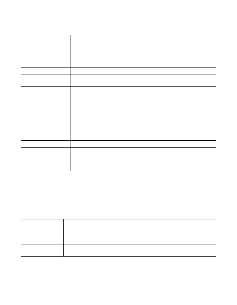
Table 3.6 Configuration Utility Physical Drive Submenu
Option Description
Rebuild Use this option to rebuild a failed physical drive that is part of a redundant
Clear Use this option to clear the data from SCSI disk drives. This is for SCSI
Force Online Use this option to change the state of the selected disk drive to Online.
Force Offline/
Remove HSP
Make Hot Spare Use this option to designate the selected disk drive as a hot spare. A hot
View Drive Information Use this option to display the drive properties for the selected physical
View Rebuild Progress Use this option to enable synchronous negotiation with a physical device.
View Rebuild Progress Use this option to view the progress of the physical drive rebuild.
SCSI Command
Qtagging
Transfer Speed Option Use this option to set the data transfer speed.
array. Data from a good drive or drives rebuilds the failed drive.
drives only.
Use this option to change the state of the selected disk drive to Fail.
spare is an idle, powered-on standby drive ready for use if another drive fails.
When a drive fails, the controller firmware automatically rebuilds the data on
the hot spare from a redundant drive or drives. Data can be rebuilt only from
logical drives with redundancy (RAID 1, 5, 10, and 50, not RAID 0). The hot
spare must be at least as large as the failed drive it is replacing.
device, such as device type, capacity, vendor ID, and device errors.
This is available only for SCSI controllers.
Use this option to set the number of queue tags per command to Disabled,
2, 3, 4, or Enhanced. The default setting is Enhanced. This option is
available for SCSI controllers only.
3.3.3.6 Channel Submenu Description
Select this option from the Configuration Utility Objects menu to choose
a channel or port on the controller. Table 3.7 lists and describes the
Channel submenu options.
Table 3.7 Configuration Utility Channel Submenu
Option Description
Termination State Use this option to control termination on the MegaRAID SCSI controller. The
SCSI Transfer Rate This option enables the user to set the SCSI transfer rate as Fast, Ultra, Ultra2,
MegaRAID SCSI controller sets this option automatically, though you can set
it manually.
Ultra160, or Ultra320 SCSI.
Configuration Utility Menu 3-13
Version 2.0 Copyright © 2003–2006 by LSI Logic Corporation. All rights reserved.
Page 62
3.3.3.7 Battery Backup Submenu Description
Select this option from the Configuration Utility Objects menu to display
information about the battery backup. Table 3.8 lists and describes the
options for the Battery Backup submenu. This option is available only on
controllers that support the battery back-up feature.
Note: If the battery is not present on the board, the battery
options do not display.
Table 3.8 Configuration Utility Battery Backup Submenu
Option Description
Backup Module Indicates whether the battery module is present.
Battery Pack Indicates whether the battery module is correctly installed.
Temperature Indicates whether the temperature is within the normal operating range.
Voltage Indicates whether the voltage is within the normal operating range.
Fast Charging Indicates whether the battery pack is charging, or if the fast charge cycle is complete.
No of Cycles Indicates the number of charge cycles that the battery pack has undergone. The
battery pack life is 1100 charge cycles. You must replace the battery pack after it
reaches this limit.
3.3.4 Clear Option
Select the Clear option from the Configuration Utility Management Menu
to clear data on one or more physical drives.
You do not have to select Clear to erase existing information on your
disks, such as a system partition. Initialization of the logical drives erases
all the information on the drive.
3.3.5 Rebuild Option
Select this option to rebuild failed disk drives. If a disk drive fails that is
in a RAID 1, 5, 10, or 50 configuration, you can recover the lost data by
rebuilding the drive. The CU can perform an automatic rebuild if hot spare
disks are available in the system. If no hot spare disks are available, the
data must be manually rebuilt. Refer to Section 3.8, “Rebuilding Failed
Disks,” on page 3-30 for the procedure on rebuilding disks.
3-14 BIOS Configuration Utility and MegaRAID Manager
Version 2.0 Copyright © 2003–2006 by LSI Logic Corporation. All rights reserved.
Page 63

3.3.6 Check Consistency Option
Select this option to verify the redundancy data in logical drives that use
RAID levels 1, 5, 10, or 50. When you select Check Consistency, the
system displays the parameters of the existing logical drives on the current
controller and a selection menu that lists the logical drives by number. The
CU automatically corrects any discrepancies with the assumption that the
data is correct and that the error exists in the parity information. However,
if the failure is a read error on a data drive, the bad data block is
reassigned with the generated data. See Section 3.10, “Checking Data
Consistency,” on page 3-32 for the Check Consistency procedure.
3.3.7 Reconstruct Option
Select this option to perform a reconstruction. A reconstruction occurs
when you change the RAID level of an array or add a physical drive to
an existing array. Refer to Section 3.11, “Reconstructing Logical Drives,”
on page 3-33 for the procedure to perform a reconstruction.
3.3.8 Select Adapter Menu
This menu item appears only if the system contains more than one
MegaRAID host adapter. The CU lists the adapters present in the system
after you choose the Select Adapter option. Select the MegaRAID
adapter that you want to configure from this menu.
Configuration Utility Menu 3-15
Version 2.0 Copyright © 2003–2006 by LSI Logic Corporation. All rights reserved.
Page 64

3.4 Detailed Configuration Instructions
This section provides detailed instructions for configuring the logical
disks and arrays in a MegaRAID system. MegaRAID provides several hot
keys that you can use during the configuration process. Table 3.9
summarizes the hot key definitions.
Table 3.9 Configuration Hot Keys
Key Function
F2 Use this option to display the manufacturer data and error count for the
selected drive.
F3 Use this option to display the configured logical drives.
F4 Use this option to designate the selected drive as a hot spare.
F10 Use this option to display the logical drive configuration screen. The option
is available only when using New Configuration or View/Add Configuration.
3.4.1 Starting the MegaRAID Configuration Utility
While the host computer boots, hold the CTRL key and press the M key
when a BIOS banner such as the following appears:
Press <Ctrl><M> to run MegaRAID BIOS Configuration Utility
This causes the CU start-up window to appear. For each MegaRAID
adapter in the host system, the CU displays the firmware version, the
DRAM size, and the status of logical drives on the adapter. If you do not
press CTRL+M within a few seconds of the prompt, the system continues
the normal boot procedure.
Note: You can access multiple controllers through the BIOS
Configuration Utility. Be sure to verify which controller you
are currently set to edit.
3.4.2 Resolving a Configuration Mismatch
A configuration mismatch happens when the configuration data in the
NVRAM and that on the hard disk drives are different. In case of a
configuration mismatch, the following message displays during the
power-on self-test (POST): Unresolved configuration mismatch
between disk(s) and NVRAM on the adapter.
3-16 BIOS Configuration Utility and MegaRAID Manager
Version 2.0 Copyright © 2003–2006 by LSI Logic Corporation. All rights reserved.
Page 65

You need to update the configuration data in either the NVRAM or on the
hard disk drive. Perform the following steps to resolve the mismatch.
Step 1. Press CTRL+M when prompted during bootup to access the
BIOS Configuration Utility.
Step 2. Select Configure → View/Add Configuration.
This gives you the option to view both the configuration on the
NVRAM and the hard drive disk.
Step 3. Select either NVRAM or configuration on disk.
Step 4. Press ESC and select YES to update the configuration data.
Step 5. Press ESC to exit, then reboot.
3.4.3 Starting MegaRAID Manager
MegaRAID Manager runs under the following operating systems:
• MS-DOS
• NetWare
• Red Hat Linux
Note: For more information about these operating systems and
driver installation, refer to the MegaRAID Device Driver
Installation User’s Guide.
To start MegaRAID Manager, ensure the program file is in your file path.
In DOS, type:
MegaConf
In NetWare, type:
load megamgr
For any other operating system (OS), refer to the documentation that
accompanied the OS.
Detailed Configuration Instructions 3-17
Version 2.0 Copyright © 2003–2006 by LSI Logic Corporation. All rights reserved.
Page 66

3.4.4 Configuring Arrays and Logical Drives
The following procedures apply to both the BIOS Configuration Utility and
MegaRAID Manager.
Step 1. Designate hot spares (optional).
See Section 3.4.6, “Designating Drives as Hot Spares” in this
section for more information.
Step 2. Select a configuration method.
See Section 3.4.7, “Creating Physical Arrays and Logical
Drives” in this section for more information.
Step 3. Create arrays using the available physical drives.
Step 4. Define logical drives using the arrays.
Step 5. Save the configuration information.
Step 6. Initialize the logical drives.
See Section 3.4.8, “Initializing Logical Drives” in this section for
more information.
3.4.5 Selecting a Configuration Method
The Configure Menu has options for Easy Configuration, New
Configuration, View/Add Configuration, or Clear Configuration.
Section 3.4.7, “Creating Physical Arrays and Logical Drives,” provides
detailed instructions for using each configuration method.
Caution: When you use the New Configuration option to create a
configuration, the existing configuration data is erased.
3.4.6 Designating Drives as Hot Spares
Hot spare drives are physical drives that power up along with the RAID
drives and operate in a standby state. If a hard drive used in a RAID
logical drive fails, a hot spare automatically takes its place and the data
on the failed drive is rebuilt on the hot spare. Hot spares can be used for
RAID levels 1, 5, 10, and 50.
The hot spare has to be at least as large as the hard drive that it
replaces. Only global hot spares can be assigned; dedicated hot spares
cannot be assigned.
3-18 BIOS Configuration Utility and MegaRAID Manager
Version 2.0 Copyright © 2003–2006 by LSI Logic Corporation. All rights reserved.
Page 67

There are two methods for designating physical drives as hot spares:
• Pressing F4 while creating arrays in Easy, New or View/Add
Configuration mode.
• Using the Objects → Physical Drive menu.
F4 Key –
When you select any configuration option, a list of all physical devices
connected to the current controller appears. Perform the following steps
to designate a drive as a hot spare:
Step 1. On the Management Menu select Configure, then a
configuration option.
Step 2. Press the arrow keys to highlight a hard drive that displays as
READY.
Step 3. Press F4 to designate the drive as a hot spare.
Step 4. Click YES to make the hot spare.
The drive displays as HOTSP.
Step 5. Save the configuration.
Objects Menu –
Step 1. On the Management Menu select Objects → Physical Drive.
A physical drive selection screen appears.
Step 2. Select a hard drive in the READY state and press ENTER to
display the action menu for the drive.
Step 3. Press the arrow keys to select Make Hot spare and press
ENTER.
The selected drive displays as HOTSP.
3.4.7 Creating Physical Arrays and Logical Drives
This subsection provides instructions for using the Easy Configuration,
New Configuration, and View/Add Configuration. LSI recommends using
drives with the same capacity in a specific array. If you use drives with
different capacities in an array, the CU treats all these drives as if they
have the capacity of the smallest drive.
Detailed Configuration Instructions 3-19
Version 2.0 Copyright © 2003–2006 by LSI Logic Corporation. All rights reserved.
Page 68

The number of physical drives in a specific array determines the RAID
levels that you can implement with the array. RAID 0 requires one or
more physical drives. RAID 1 requires exactly two physical drives.
RAID 5 requires at least three physical drives.
Note: The firmware does not support creation of logical drives
greater than 2 Tbytes.
3.4.7.1 Logical Drive Parameters
The following paragraphs describe the parameters that you can set for
the logical drives, which include the RAID level, stripe size, read policy,
write policy, cache policy, and spanning mode.
After you create an array or arrays, you can select the parameters for the
logical drive. Table 3.10 contains descriptions of the parameters.
3-20 BIOS Configuration Utility and MegaRAID Manager
Version 2.0 Copyright © 2003–2006 by LSI Logic Corporation. All rights reserved.
Page 69

Table 3.10 Logical Drive Parameters and Descriptions
Parameter Description
RAID Level The number of physical drives in a specific array determines the RAID levels that can
be implemented with the array.
Stripe Size The stripe size parameter specifies the size of the segments written to each disk in
a RAID 1, 5, 10, or 50 configuration. You can set the stripe size as 8, 16, 32, 64, or
128 Kbytes. The default is 64 Kbytes.
A larger stripe size produces higher read performance, especially if your computer
does mostly sequential reads. If your computer regularly performs random read
requests, select a smaller stripe size.
Write Policy Write Policy specifies the cache write parameter. You can set the write policy to
Write-back or Write-through.
In Write-back caching, the controller sends a data transfer completion signal to the
host when the controller cache has received all the data in a transaction. LSI
recommends using this setting in standard mode.
Note: If Write-back is enabled and the system is quickly turned off and on,
the RAID controller may hang when flushing cache memory.
Controllers that contain a battery backup default to Write-back
caching.
In Write-through caching, the controller sends a data transfer completion signal to the
host when the disk subsystem has received all the data in a transaction.
Write-through caching has a data security advantage over write-back caching, while
write-back caching has a performance advantage.
Note: Enabling clustering turns off write cache. The MegaRAID 320-2
controller supports clustering.
Read Policy The read parameter determines the type of read option for the logical drive. You can
set this parameter to Normal, Read-ahead, or Adaptive. The default setting is Normal.
The options are
• Normal specifies that the controller reads only the requested data and does not
read ahead for the current logical drive.
• Read-ahead specifies that the controller uses read-ahead for the current logical
drive. Read-ahead capability allows the adapter to read sequentially ahead of
requested data and store the additional data in cache memory, anticipating that
the data is needed soon. Read-ahead supplies sequential data faster, but is not
as effective when accessing random data.
• Adaptive specifies that the controller begins using read-ahead if the two most
recent disk accesses occurred in sequential sectors. If all read requests are
random, the algorithm reverts to Normal; however, all requests are still evaluated
for possible sequential operation.
Detailed Configuration Instructions 3-21
Version 2.0 Copyright © 2003–2006 by LSI Logic Corporation. All rights reserved.
Page 70

Table 3.10 Logical Drive Parameters and Descriptions (Cont.)
Parameter Description
Cache Policy Use this option to enable read buffering in cache memory. Cache Policy applies to
Span The RAID controller supports spanning of RAID 1 and 5 arrays. You can span two or
reads on a specific logical drive. It does not affect the Read-ahead cache. The default
setting is Direct I/O.
• Cached I/O specifies that the controller buffers reads in cache memory.
• Direct I/O specifies that reads and writes are not buffered in cache memory. Direct
I/O does not override the read policy settings. Data is transferred to cache and the
host concurrently. If the same data block is read again, it comes from cache memory.
more RAID 1 arrays into a RAID 10 array and two or more RAID 5 arrays into a RAID
50 array. The maximum number of drives that you can span is eight. For two arrays
to be spanned, they must have the same stripe width (they must contain the same
number of physical drives).
The options are:
Yes – Array spanning is enabled for the current logical drive. The logical drive can
occupy space in more than one array.
No – Array spanning is disabled for the current logical drive. The logical drive can
occupy space in only one array.
3.4.7.2 Easy Configuration
In Easy Configuration, the CU associates each hard drive with a single
logical drive. If logical drives have already been configured, the CU does
not change their configuration. Perform the following steps to create
arrays using Easy Configuration.
Step 1. Select Configure → Easy Configuration from the MegaRAID
CU Main menu.
The Management Menu array selection menu appears.
Step 2. Press the arrow keys to select specific physical drives.
Step 3. Press the spacebar to associate the selected physical drive
with the current array.
After you associate a physical drive with a current array, the
indicator forthe drive changes from READY to ONLIN A[array
number]-[drive number]. For example, ONLIN A2-3
indicates array 2 with disk drive 3.
Step 4. Press ENTER after you finish creating the current array.
3-22 BIOS Configuration Utility and MegaRAID Manager
Version 2.0 Copyright © 2003–2006 by LSI Logic Corporation. All rights reserved.
Page 71

The logical drive configuration screen appears. It displays the
logical drive number, RAID level, logical drive size, the number
of stripes in the physical array, the stripe size, and the state of
the logical drive.
Note: The firmware does not support creation of logical drives
greater than 2 Tbytes.
Step 5. Highlight RAID and press ENTER to set the RAID level for the
logical drive.
The CU displays the available RAID levels for the current
logical drive.
Step 6. Select a RAID level and press ENTER.
Step 7. Click Advanced Menu to open the menu for logical drive settings.
Step 8. Set the Stripe Size.
Step 9. Set the Write Policy.
Step 10. Set the Read Policy.
Step 11. Set the Cache Policy.
Step 12. Press ESC to exit the Advanced Menu.
Step 13. After you define the current logical drive, select Accept and
press ENTER.
The array selection screen appears if any disk drives remain
unconfigured.
Step 14. Repeat these steps to configure additional logical drives,
if desired.
MegaRAID supports up to 40 logical drives per controller.
Step 15. If you are through configuring logical drives, press ESC to exit
Easy Configuration.
Step 16. Save the configuration when prompted.
Step 17. Initialize the logical drives.
Refer to Section 3.4.8, “Initializing Logical Drives,” on page 3-26
for detailed instructions.
Detailed Configuration Instructions 3-23
Version 2.0 Copyright © 2003–2006 by LSI Logic Corporation. All rights reserved.
Page 72

3.4.7.3 New Configuration and View/Add Configuration
New Configuration and View/Add Configuration associate logical drives
with partial and/or multiple physical arrays. New Configuration deletes the
existing configuration and replaces it with the configuration that you specify.
View/Add Configuration lets you view or modify an existing configuration.
Caution: The New Configuration option erases the existing
configuration data when you save the new array
configuration.
Perform the following steps to configure a disk array using
New Configuration or View/Add Configuration.
Step 1. Select Configure → New Configuration or Configure →
View/Add Configuration from the Management Menu.
The CU displays an array selection window.
Step 2. Use the arrow keys to select specific physical drives to include
in the array.
Step 3. Press the spacebar to associate the selected physical drive
with the current array.
The indicator for the selected drive changes from READY to
ONLIN A[array number]-[drive number]. For example,
ONLIN A2-3 means disk drive 3 in array 2.
Step 4. Press ENTER after you create the current array.
Step 5. Press F10 to configure logical drives.
Step 6. Highlight RAID and press ENTER to set the RAID level for the
logical drive.
The CU displays the available RAID levels for the current
logical drive.
Step 7. Select a RAID level and press ENTER.
If you have two RAID 1 or RAID 5 arrays, the spanning mode
is set automatically for RAID 10 and RAID 50.
Step 8. Move the cursor to Size and press ENTER to set the logical
drive size.
3-24 BIOS Configuration Utility and MegaRAID Manager
Version 2.0 Copyright © 2003–2006 by LSI Logic Corporation. All rights reserved.
Page 73

By default, the logical drive size associates the available space
in the array(s) with the current logical drive, accounting for the
Span setting and partially-used array space.
Step 9. Highlight Span and press ENTER.
Table 3.11 describes the spanning mode options.
Table 3.11 Spanning Mode Options
Spanning Option Description
CanSpan This option enables array spanning for the current logical
NoSpan This option disables array spanning for the current logical
drive. The logical drive can occupy space in more than
one array.
drive. The logical drive can occupy space in only one array.
For two arraysto be spannable, they must have the same stripe
width and must be consecutively numbered. For example, if
Array 2 contains four disk drives, you can span it only with
Array 1 and/or Array 3, and only if Arrays 1 and 3 each contain
four disk drives. If the criteria are not met, the CU ignores the
span setting for the current logical drive.
Step 10. Select Advanced Menu to open the menu for logical
drive settings.
Step 11. Set the Stripe Size by pressing ENTER and selecting a value.
Step 12. Set the Write Policy.
Step 13. Set the Read Policy.
Step 14. Set the Cache Policy.
Step 15. Press ESC to exit the Advanced Menu.
Step 16. After you define the current logical drive, select Accept and
press ENTER.
If space remains in the arrays, the next logical drive to be
configured appears. If the array space has been used, a list of
the existing logical drives appears.
Step 17. Press any key to continue, then respond to the Save prompt.
Detailed Configuration Instructions 3-25
Version 2.0 Copyright © 2003–2006 by LSI Logic Corporation. All rights reserved.
Page 74

Step 18. Initialize the logical drives you just configured.
Section 3.4.8, “Initializing Logical Drives,” on page 3-26
provides detailed instructions.
3.4.8 Initializing Logical Drives
You can initialize the logical drives individually or in batches. Individual
initialization initializes a single logical disk. Batch initialization initializes
up to 40 logical drives simultaneously.
Note: If there are five or more drives in a RAID 5 array,
background batch initialization starts automatically.
Batch Initialization – Perform the following step to initialize logical
drives.
Step 1. Select Initialize from the Management Menu.
A list of the current logical drives appears.
Step 2. Press the spacebar to select the desired logical drive for
initialization.
Optionally, you can press F2 to select or deselect all
logical drives.
Step 3. After you finish selecting logical drives, press F10 and select
Yes at the confirmation prompt.
The CU displays a bar graph showing the initialization progress.
Step 4. When initialization is complete, press any key to continue or
press ESC to display the Management Menu.
Individual Initialization –
Step 1. Select Objects → Logical Drive from the Management Menu.
Step 2. Select the logical drive to be initialized.
Step 3. Select Initialize from the action menu.
Initialization progress appears as a bar graph on the screen.
Step 4. When initialization completes, press any key to display the
previous menu.
3-26 BIOS Configuration Utility and MegaRAID Manager
Version 2.0 Copyright © 2003–2006 by LSI Logic Corporation. All rights reserved.
Page 75

3.5 Deleting Logical Drives
This RAID controller supports the ability to delete any unwanted logical
drives and use that space for a new logical drive. You can have an array
with multiple logical drives and delete a logical drive without deleting the
whole array.
After you delete a logical drive, you can create a new one. You can use
the configuration utilities to create the next logical drive from the
noncontiguous free space (holes), and from the newly created arrays.
The configuration utility provides a list of configurable arrays where there
is a space to configure.
Note: The deletion of the logical drive can fail under certain
conditions: During a rebuild, initialization or check
consistency of a logical drive, if that drive has a higher
logical drive number than the drive you want to delete.
Perform the following steps to delete logical drives:
Step 1. Select Objects → Logical Drive from the Management Menu.
The logical drives display.
Step 2. Use the arrow key to highlight the logical drive you want to
delete.
Step 3. Press F5 to delete the logical drive.
This deletes the logical drive and makes the space it occupied
available for you to make another logical drive.
3.6 Performing Drive Roaming
Drive roaming occurs when the hard drives are changed to different
channels or different target IDs on the same controller. When the drives
are placed on different channels, the controller detects the RAID
configuration from the configuration data on the drives.
Deleting Logical Drives 3-27
Version 2.0 Copyright © 2003–2006 by LSI Logic Corporation. All rights reserved.
Page 76

Configuration data is saved in both nonvolatile random access memory
(NVRAM) on the RAID controller and on the hard drives attached to the
controller. This maintains the integrity of the data on each drive, even if
the drives have changed their target ID.
Note: In a clustering environment, drive roaming is supported
within the same channel only. Drive roaming between
channels in a cluster is not supported.
Note: Driveroaming from multiple controllers to a cluster-configured
controller is not supported.
Perform the following steps to use drive roaming:
Step 1. Turn off all power to the system and all hard drives, enclosures,
and system components, then disconnect power cords from
the system.
Step 2. Open the host system by following the instructions in the host
system technical documentation.
Step 3. Remove the unshielded, twisted pair, SCSI ribbon cable
connectors from the internal drives or the shielded cables from
the external drives you want to move.
- Make sure pin 1 on the cable matches pin 1 on the connector.
- Make sure that the SCSI cables conform to all SCSI
specifications.
Step 4. Connect the hard drives to different connectors on the cable.
Step 5. Determine the SCSI ID and SCSI termination requirements.
Note: Thedefault for SCSI termination is onboard SCSI termination
enabled. See the MegaRAID 320 Storage Adapters User’s
Guide for more information about SCSI termination.
Step 6. Perform a safety check.
◊ Make sure all cables are properly attached.
◊ Make sure the RAID controller is properly installed.
◊ Close the cabinet of the host system.
◊ Turn power on after completing the safety check.
Step 7. Power on the system.
The controller then detects the RAID configuration from the
configuration data on the drives.
3-28 BIOS Configuration Utility and MegaRAID Manager
Version 2.0 Copyright © 2003–2006 by LSI Logic Corporation. All rights reserved.
Page 77

3.7 Performing Drive Migration
Drive migration is the transfer of a set of hard drives in an existing
configuration from one controller to another. If you put the hard drives on
a new controller, the controller must have a clear configuration.
Drive migration is the transfer of a set of hard drives in an existing
configuration from one controller to another. If you put the hard drives on
a new controller, the controller must have a clear configuration. To keep
the original configuration, the drives must remain on the same channel
and be reinstalled in the same order as were on the previous controller.
Note: Drive roaming and drive migration cannot be supported at
the same time. The MegaRAID controller can support
either drive roaming or drive migration, but not both at the
same time.
The drives must remain on the same channel and be reinstalled in the
same order as in the original configuration. You can perform online RAID
level migration when you do this. In addition, no reboot is necessary after
capacity expansion.
Perform the following steps to migrate drives:
Step 1. Turn off all power to the system and all hard drives, enclosures,
and system components, then disconnect power cords from the
systems.
Step 2. Open the host systems by following the instructions in the host
system technical documentation.
Step 3. Remove the unshielded, twisted pair, SCSI ribbon cable
connectors from the internal drives or the shielded cables from
the external drives you want to migrate.
◊ Make sure pin 1 on the cable matches pin 1 on the connector.
◊ Make sure that the SCSI cables conform to all SCSI
specifications.
Step 4. Remove the hard drives from the first system and insert them
into drive bays on the second.
Step 5. Connect the SCSI cables to the hard drives in the second system.
Step 6. Determine the SCSI ID and SCSI termination requirements.
Performing Drive Migration 3-29
Version 2.0 Copyright © 2003–2006 by LSI Logic Corporation. All rights reserved.
Page 78

Note: Thedefault for SCSI termination is onboard SCSI termination
enabled. See the MegaRAID 320 Storage Adapters User’s
Guide for more information of SCSI termination.
Step 7. Perform a safety check.
◊ Make sure all cables are properly attached.
◊ Make sure the RAID controller is properly installed.
◊ Close the cabinet of the host system.
◊ Turn power on after completing the safety check.
Step 8. Power on the system.
The controller then detects the RAID configuration from the
configuration data on the drives.
3.8 Rebuilding Failed Disks
If hot spare disks are present in the system, the MegaRAID controller
automatically uses them to rebuild failed disks.
3.8.1 Rebuild Types
Table 3.12 describes automatic and manual rebuilds.
Table 3.12 Rebuild Types
Type Description
Automatic
Rebuild
Manual
Rebuild
3-30 BIOS Configuration Utility and MegaRAID Manager
If you have configured hot spares, the RAID controller automatically tries to use them to
rebuild failed disks. Select Objects → Physical Drive to display the list of physical drives
while a rebuild is in progress. The hot spare drive changes to REBLD A[array number][drive number], indicating the hard drive is being replaced by the hot spare. For example,
REBLD A01-02 indicates that the data is being rebuilt in array 1 on hard drive 2.
Manual rebuild is necessary if no hot spares with enough capacity to rebuild the failed
drives are available.You must insert a drive with enough storage into the subsystem
before rebuilding the failed drive.
The CU allows manual rebuild for an individual drive or a group of drives. Rebuilding a
group of drives is done through the batch mode. Use the following procedures to rebuild
a failed drive manually in individual or batch mode.
Version 2.0 Copyright © 2003–2006 by LSI Logic Corporation. All rights reserved.
Page 79

3.8.2 Manual Rebuild – Rebuilding an Individual Drive
To perform a batch rebuild on an individual drive, follow these steps:
Step 1. Select Objects → Physical Drive from the Management Menu.
A device selection window displays the devices connected to
the current controller.
Step 2. Designate an available drive as a hot spare before the
rebuild starts.
See Section 3.4.6, “Designating Drives as Hot Spares” for
instructions on designating a hot spare.
Step 3. Press the arrow keys to select the failed physical drive you want
to rebuild, then press ENTER.
Step 4. Select Rebuild from the action menu and respond to the
confirmation prompt.
Rebuilding can take some time, depending on the drive capacity.
Step 5. When the rebuild is complete, press any key to display the
previous menu.
3.8.3 Manual Rebuild – Rebuilding in Batch Mode
To perform a batch rebuild on a group of drives, follow these steps:
Step 1. Select Rebuild from the MegaRAID Configuration Utility main
menu. The CU displays a device selection window that marks
the failed drives with FAIL indicators.
Step 2. Press the arrow keys to select all drives to be rebuilt. Press the
spacebar to select the chosen physical drive for rebuild.
Step 3. After selecting the physical drives, press F10, and select Yes at
the confirmation prompt. The indicators for the selected drives
change to REBLD.
Step 4. When rebuild is complete, press any key to continue. Press
ESC to display the main menu.
Rebuilding Failed Disks 3-31
Version 2.0 Copyright © 2003–2006 by LSI Logic Corporation. All rights reserved.
Page 80

3.9 FlexRAID Virtual Sizing
The FlexRAID Virtual Sizing option can no longer be enabled on the
MegaRAID 320-1 or 320-2 controllers. This option allowed the
Windows NT and NetWare 5.1 operating systems to use the new space
of a RAID array immediately after you added capacity online or
performed a reconstruction.
If you have this option enabled on older cards, you need to disable it,
then upgrade the firmware. Perform the following steps to do this:
Step 1. Go to the www.lsilogic.com web site.
Step 2. Download the latest firmware and driver to a diskette or directly
to your system.
The download is an executable file.
Step 3. Unzip the file and extract it to a blank diskette.
Step 4. Boot with a DOS diskette to the DOS prompt.
Step 5. Insert the diskette with the extracted files and type mflash to
flash the firmware.
3.10 Checking Data Consistency
Select this option to verify the data redundancy in logical drives that use
RAID levels 1, 5, 10, and 50. (RAID 0 does not provide data
redundancy.) The parameters of the existing logical drives appear.
Discrepancies are automatically corrected when the data is correct.
However, if the failure is a read error on a data drive, the bad data block
is reassigned and the data is regenerated.
Important: LSI recommends that you run periodic data consistency
checks on a redundant array. This allows detection and
automatic replacement of bad blocks. Finding a bad block
during a rebuild of a failed drive is a serious problem, as the
system does not have the redundancy to recover the data.
3-32 BIOS Configuration Utility and MegaRAID Manager
Version 2.0 Copyright © 2003–2006 by LSI Logic Corporation. All rights reserved.
Page 81

Perform the following steps to run Check Consistency.
Step 1. Select Check Consistency from the Management Menu.
Step 2. Press the arrow keys to highlight the desired logical drives.
Step 3. Press the spacebar to select or deselect a drive for consistency
checking.
Step 4. Press F2 to select or deselect all the logical drives.
Step 5. Press F10 to begin the consistency check.
A progress graph for each selected logical drive displays.
Step 6. When the check is finished, press any key to clear the
progress display.
Step 7. Press ESC to display the Management Menu.
(To check an individual drive, select Objects → Logical Drives from the
Management Menu, the desired logical drive(s), then Check Consistency
on the action menu.)
3.11 Reconstructing Logical Drives
A reconstruction occurs when you change the RAID level of an array or
add a physical drive to an existing array. Perform the following steps to
reconstruct a logical drive:
Step 1. Move the arrow key to highlight Reconstruct on the
Management Menu.
Step 2. Press ENTER.
The window entitled Reconstructables displays. This contains
the logical drives that can be reconstructed. You can press F2
to view logical drive information or ENTER to select the
reconstruct option.
Step 3. Press ENTER.
The next reconstruction window displays. The options on this
window are the spacebar to select a drive, ENTER to open the
reconstruct menu, and F3 to display logical drive information.
Reconstructing Logical Drives 3-33
Version 2.0 Copyright © 2003–2006 by LSI Logic Corporation. All rights reserved.
Page 82

Step 4. Press ENTER to open the reconstruct menu.
The menu items are RAID level, stripe size, and reconstruct.
Step 5. To change the RAID level, select RAID with the arrow key, and
press ENTER.
Step 6. Select Reconstruct and press ENTER to reconstruct the
logical drive.
Note: After you start the reconstruct process, you must wait until
it is complete. You cannot reboot, cancel, or exit until the
reconstruction is complete.
3.12 Replacing a Failed Controller Containing Data in
the TBBU
The MegaRAID Transportable Battery Backup Module (TBBU) is a cache
memory module with an integrated battery pack. The module provides
an uninterrupted power source to the module if power is unexpectedly
interrupted while there is still cached data present. If the power failure is
the result of the MegaRAID controller itself failing, then the TBBU can be
moved to a new controller and the data recovered. The replacement
controller must have a cleared configuration.
Perform the following steps to replace a failed controller with data in the
transportable battery backup unit.
Step 1. Power-down the system and drives.
Step 2. Remove the failed controller from the system.
Step 3. Remove the TBBU from the failed controller.
Step 4. Insert the TBBU into the replacement controller.
Step 5. Insert the replacement controller into the system.
Step 6. Power-on the system.
The controller then reads the disk configuration into NVRAM
and flush cache data to the logical drives.
3-34 BIOS Configuration Utility and MegaRAID Manager
Version 2.0 Copyright © 2003–2006 by LSI Logic Corporation. All rights reserved.
Page 83

Resolving a Configuration Mismatch in a Replacement Controller –
When you move a TBBU from the failed controller to a replacement
controller, a configuration mismatch occurs if the replacement controller
has a previous configuration. A configuration mismatch happens when
the configuration data in the NVRAM and that on the hard disk drives
are different.
In case of a configuration mismatch, the following message displays
during the power-on self-test (POST): Unresolved configuration
mismatch between disk(s) and NVRAM on the adapter.
In this situation, you need to update the configuration data in the NVRAM
with the data from the hard disk drive. Perform the following steps to
resolve the mismatch.
Step 1. Press CTRL+M when prompted during bootup to access the
BIOS Configuration Utility.
Step 2. Select Configure → View/Add Configuration.
This gives you the option to view both the configuration on the
NVRAM and the hard drive disk.
Step 3. Select the configuration on disk.
Step 4. Press ESC and select YES to update the NVRAM.
Step 5. Press ESC to exit, then reboot.
3.13 Using a Preloaded System Drive
Note: Define a preloaded system drive as the first logical drive. If
the drive is not a boot device, the logical drive number is
not critical.
You can use the MegaRAID controller as the adapter for this drive by
performing the following steps:
Step 1. Connect the drive to the channel or port on the MegaRAID
controller.
Step 2. Boot the computer, then start the Configuration Utility.
Step 3. Select Easy Configuration from the Configure menu.
Using a Preloaded System Drive 3-35
Version 2.0 Copyright © 2003–2006 by LSI Logic Corporation. All rights reserved.
Page 84

Step 4. Press the cursor keys to select the preloaded drive.
Step 5. Press the spacebar.
The preloaded drive now becomes an array element.
Step 6. Press ENTER. The preloaded drive is a one-disk array.
Step 7. Display the logical drive configuration screen.
Step 8. Set the read policy and cache option on the Advanced menu.
Step 9. Press ESC to exit the Advanced menu, then highlight Accept
and press ENTER.
Step 10. Press ESC and select Yes at the Save prompt.
Step 11. Exit Configuration Utility and reboot.
Step 12. Set the host system to boot from the drive.
3.14 Exiting MegaRAID Configuration Utility
Press ESC when the MegaRAID Configuration Utility management menu
is displayed to exit MegaRAID Configuration Utility.
3-36 BIOS Configuration Utility and MegaRAID Manager
Version 2.0 Copyright © 2003–2006 by LSI Logic Corporation. All rights reserved.
Page 85

Chapter 4
WebBIOS
Configuration Utility
This chapter describes the WebBIOS Configuration Utility and consists
of the following sections:
• Section 4.1, “General Description”
• Section 4.2, “Quick Configuration Steps”
• Section 4.3, “Starting the WebBIOS Configuration Utility on the
Host Computer”
• Section 4.4, “Screen and Option Descriptions”
• Section 4.5, “Configuring RAID Arrays and Logical Drives”
4.1 General Description
The WebBIOS Configuration Utility (CU) provides a Web-based utility to
configure and manage RAID volumes. The utility configures disk arrays
and logical drives. Its operation is independent of the operating system
because the utility resides in the MegaRAID BIOS.
The WebBIOS CU performs the following actions:
• Displays adapter properties
• Scans devices
• Creates physical arrays
• Defines logical drives
• Displays logical drive properties
• Initializes logical drives
• Checks data for consistency
MegaRAID Configuration Software User’s Guide 4-1
Version 2.0 Copyright © 2003–2006 by LSI Logic Corporation. All rights reserved.
Page 86

• Displays the physical properties of devices
• Allows capacity expansion and drive migration
The WebBIOS CU provides a configuration wizard to guide you through
the configuration of logical drives and physical arrays.
4.2 Quick Configuration Steps
This section provides the steps to configure arrays and logical drives
using the WebBIOS CU. The following sections describe how to perform
each action using the WebBIOS CU. The steps are:
Step 1. Power-on the system.
Step 2. Start the WebBIOS CU by pressing CTRL+H.
Step 3. Start the Configuration Wizard.
Step 4. Select a configuration method.
Step 5. Create arrays using the available physical drives.
Step 6. Define the logical drive(s) using the space in the arrays.
Step 7. Initialize the new logical drives.
4.3 Starting the WebBIOS Configuration Utility on the
Host Computer
While the host computer boots, hold down the CTRL key and press the
H key when the following appears:
Copyright© LSI Logic Corporation
Press <Ctrl><M> to Run Configuration Utility
Or press <Ctrl><H> for WebBIOS
After you press CTRL+H, the Adapter Selection screen displays, as
shown in Figure 4.1. This screen lists the adapters, adapter numbers,
and firmware versions. Select an adapter and press the Start button to
begin the configuration.
4-2 WebBIOS Configuration Utility
Version 2.0 Copyright © 2003–2006 by LSI Logic Corporation. All rights reserved.
Page 87

Note: If there is a configuration mismatch between the disks and
the nonvolatile random access memory (NVRAM), the CU
displays the Select Configuration screen.
Figure 4.1 WebBIOS Adapter Selection Screen
Starting the WebBIOS Configuration Utility on the Host Computer 4-3
Version 2.0 Copyright © 2003–2006 by LSI Logic Corporation. All rights reserved.
Page 88

4.4 Screen and Option Descriptions
This section describes the various WebBIOS screens and options.
4.4.1 WebBIOS Toolbar Options
Table 4.1 describes the WebBIOS toolbar icons.
Table 4.1 WebBIOS Toolbar Icon Descriptions
Icon Description
Click this icon to return to the main screen.
Click this icon to return to the page you accessed immediately before the current page.
Click this icon to exit the WebBIOS program.
Click this icon to display the adapters that you can select.
Click this icon to scan for devices connected to your system.
Click this icon to display the properties of the adapter, such as the firmware version,
BIOS version, RAM size, and initiator ID.
Click the icon to access the Configuration Wizard so that you can configure the
arrays and logical drives.
Click this icon to turn off the sound on the alarm.
Click this icon to display the WebBIOS version, browser version, and HTML
interface engine.
4-4 WebBIOS Configuration Utility
Version 2.0 Copyright © 2003–2006 by LSI Logic Corporation. All rights reserved.
Page 89

4.4.2 Main Screen
When you press CTRL+H on the host computer, the WebBIOS CU
displays the main screen.
Figure 4.2 WebBIOS Main Screen
From the main screen you can scan the devices connected to the
controller, select a MegaRAID adapter if multiple adapters are in the
system, alternate between the physical devices view and the logical
devices view, and access other screens. The main screen provides the
following options:
• Adapter Properties
• Scan Devices
• SCSI Channel Properties
• Logical Drives
• Physical Drives
• Configuration Wizard
Screen and Option Descriptions 4-5
Version 2.0 Copyright © 2003–2006 by LSI Logic Corporation. All rights reserved.
Page 90

• Adapter Selection
• Physical View
• Exit
4.4.3 Adapter Properties Screen
The Adapter Properties screen, as Figure 4.3 shows, allows you to view
and configure the software and hardware of the selected adapter. You
access the Adapter Properties screen from the WebBIOS main screen.
Figure 4.3 WebBIOS Adapter Properties Screen
4-6 WebBIOS Configuration Utility
Version 2.0 Copyright © 2003–2006 by LSI Logic Corporation. All rights reserved.
Page 91

Table 4.2 describes the Adapter Properties menu options.
Table 4.2 WebBIOS Adapter Properties Menu Options
Option Description
Firmware Version This option displays the firmware version number.
BIOS Version This option displays the BIOS version number.
Battery Backup This option indicates whether battery backup is present. If present, click
RAM Size This option displays the size of the random access memory (RAM).
Cluster Mode Use this option to enable or disable cluster mode. The default is Disabled.
Initiator ID Identifying number for the MegaRAID card. The default is 7. You can
Rebuild Rate Use this option to select the rebuild rate for drives attached to the selected
FlexRAID PowerFail Use this option to enable the FlexRAID PowerFail feature, which allows drive
Alarm Control Use this option to enable, disable, or silence the onboard alarm tone
Adapter BIOS Use this option to enable the adapter BIOS. The default is Enabled. If the
Set Factory Defaults Use this option to load the default MegaRAID WebBIOS CU settings. The
ChkConst Restore When enabled, this option allows the firmware to fix medium errors found
Present to display the following battery details: temperature, voltage,
progress of charging, number of cycles, and reset option.
When this is disabled, the system operates in standard mode. A cluster is
a grouping of independent servers that can access the same data storage
and provide services to a common set of clients.
change the Initiator ID only when you are in cluster mode. You cannot
change the ID while in standard mode. The ID can be a number from 0 to
15. We recommend that you use 6 or 7. When you are in standard mode,
the ID is always 7.
adapter. The default is 30 percent. The rebuild rate is the percentage of
system resources dedicated to rebuilding a failed drive. A rebuild rate of 100
percent means the system is totally dedicated to rebuilding a failed drive.
reconstruction, rebuild, or check consistency to continue when the system
restarts after a power failure, reset, or hard boot. The default is Enabled.
generator. The default is Disabled.
boot device is on the RAID controller, the BIOS must be enabled; otherwise,
the BIOS should be disabled or it might not be possible to use a boot
device elsewhere.
default is No.
during a data consistency check. The medium error is logged in the
NVRAM. The default is Enabled.
Screen and Option Descriptions 4-7
Version 2.0 Copyright © 2003–2006 by LSI Logic Corporation. All rights reserved.
Page 92

Table 4.2 WebBIOS Adapter Properties Menu Options (Cont.)
Option Description
Force Boot Option Use this option to determine how the BIOS handles a configuration
Bios Stops on Error When set to On, the BIOS stops in case of a problem with the configuration.
BIOS Echoes Messages When set to On (the default), all controller BIOS messages display during
Bios Config AutoSelection Use this option if there is a mismatch between configuration data in the
Spinup Parameters Use this option to set the timing for spinning up the hard disk drives in the
Fast Initialization When enabled, zeros are written to the first sector of the logical drive so
mismatch. A configuration mismatch occurs when the configuration data on
the NVRAM and that on the hard drives are different.
If you set the Force Boot Option to On, then when a configuration mismatch
occurs, the BIOS reads the configuration data that exists on the hard drive,
writes it on NVRAM, and reboots the system. The options are On and Off.
The default is On.
This gives you the option to enter the configuration utility to resolve the
problem. The default is On.
bootup.
drives and NVRAM, so you can select a method to resolve it. The options
are NVRAM, Disk, and User. The default is User.
computer. The options are Automatic, 2 per 6 sec, 4 per 6 sec,
or 6 per 6 sec. The default is 2 per 6 sec.
that initialization occurs in 2 to 3 seconds. The options are Enabled and
Disabled. The default is Enabled.
When disabled, a full initialization takes place on the entire logical drive. On
a larger logical drive, LSI recommends disabling fast initialization, then
initializing. Otherwise, the controller runs a background consistency check
within 5 minutes of reboot or RAID 5 creation.
PCI Delay Trans Use this option to enable PCI delay transfers, which improve performance
on some older system boards. The choices are Enabled and Disabled.
The default is Enabled.
Auto Rebuild Use this option to automatically rebuild drives when they fail. The options
are Enabled and Disabled. The default is Enabled.
2
Class Emulation Mode Use this option to select I
mode. The default is Mass Storage. This option allows the firmware to
2
use I
O drivers or regular drivers.
O or Mass Storage as the class emulation
Temporary RAID Offline Use this option to allow the firmware to bring all the drives in an array back
online, except for the first failed drive. The default is Disabled. Enabling
this option gives you access to the array. If disabled, you cannot access the
array if there are two or more failed drives in the array.
4-8 WebBIOS Configuration Utility
Version 2.0 Copyright © 2003–2006 by LSI Logic Corporation. All rights reserved.
Page 93

4.4.4 Scan Devices Option
When you select the Scan Devices option on the main screen, WebBIOS
checks the physical and logical drives for any changes of the drive status.
WebBIOS displays the results of the scan in the physical and logical
drive descriptions.
4.4.5 SCSI Channel Properties
The SCSI Channel Properties option displays the following information
about the selected SCSI channel (bus):
• Channel Width (number of bits)
• Termination (enabled or disabled)
• SCSI Capabilities (data transfer speed)
4.4.6 Logical Drive Screen
You can access the Logical Drive screen, as shows in Figure 4.4,by
clicking a logical drive in the logical drive list on the main screen. The
Logical Drive screen provides options to:
• Set logical drive policies (read, write, I/O, virtual sizing)
• Initialize the logical drives
• Check consistency
• Display the logical drive properties
• Remove a physical drive from an array
• Delete a logical drive
• Select drive migration only or drive migration with addition
You can press Go to perform the selected action or Reset to delete
any changes.
Screen and Option Descriptions 4-9
Version 2.0 Copyright © 2003–2006 by LSI Logic Corporation. All rights reserved.
Page 94

Figure 4.4 WebBIOS Logical Drive Screen
4.4.6.1 Initialization
This option initializes the selected logical drive by writing zeroes to the
entire volume (if fast initialization is selected, zeroes are written to the
first sector only).
Note: After you define a logical drive, WebBIOS asks you for
initialization of the logical drive. LSI does not recommended
choosing to initialize, as a background initialization may run.
4.4.6.2 Check Consistency
This option verifies that the redundancy data is correct and available for
arrays using RAID 1, 5, 10, or 50. If a difference in the data is found, the
MegaRAID adapter assumes that the data is accurate and automatically
corrects the parity value.
4-10 WebBIOS Configuration Utility
Version 2.0 Copyright © 2003–2006 by LSI Logic Corporation. All rights reserved.
Page 95

4.4.6.3 Logical Drive Deletion
This option deletes a logical drive. The RAID controller supports the
ability to delete any unwanted logical drives and use that space for a new
logical drive. The configuration utility provides a list of configurable arrays
where there is a space to configure. You can have an array with multiple
logical drives and delete a logical drive without deleting the whole array.
Note: The deletion of the logical drive can fail under certain
4.4.6.4 Drive Migration
Drive migration is the transfer of a set of hard drives in an existing
configuration from one controller to another. If you put the hard drives on
a new controller, the controller must have a clear configuration. The
drives must remain on the same channel and must be reinstalled in the
same order as in the original configuration.
In addition, the drives must be on the same channel/target as they were
on the previous controller to keep the same configuration.
conditions: During a rebuild, initialization or check
consistency of a logical drive, if that drive has a higher
logical drive number than the drive you want to delete.
Note: For more information and the procedure for drive migration,
refer to Section 3.7, “Performing Drive Migration,” page 3-29.
Screen and Option Descriptions 4-11
Version 2.0 Copyright © 2003–2006 by LSI Logic Corporation. All rights reserved.
Page 96

4.4.7 Physical Drive Screen
This screen, as Figure 4.5 shows, displays the physical drives for each
channel or port. This screen displays the properties for the selected
physical drive, including drive size, drive state, SCSI level,and drive health.
You can use this screen to make hot spares and format a hard drive.
Figure 4.5 WebBIOS Physical Drive Screen
4-12 WebBIOS Configuration Utility
Version 2.0 Copyright © 2003–2006 by LSI Logic Corporation. All rights reserved.
Page 97

4.4.8 Configuration Mismatch Screen
A configuration mismatch occurs when the configuration data in the
NVRAM and that on the hard drives are different. You can use the
Configuration Mismatch screen, as shown in Figure 4.6, to resolve the
mismatch by doing one of the following:
• Select Create New Configuration to delete the previous configuration
and create a new configuration
• Select View Disk Configuration to restore the configuration from the
hard drive
• Select View NVRAM Configuration to restore the configuration from
the NVRAM
Figure 4.6 WebBIOS Configuration Mismatch Screen
Screen and Option Descriptions 4-13
Version 2.0 Copyright © 2003–2006 by LSI Logic Corporation. All rights reserved.
Page 98

4.4.9 Configuration Wizard Option
This option enables you to clear a configuration, create a new
configuration, or add a configuration. Section 4.5, “Configuring RAID
Arrays and Logical Drives,” provides detailed steps for using the
Configuration Wizard.
4.4.10 Adapter Selection Option
When you select this option on the main screen, the configuration utility
displays a list of the MegaRAID adapters in the system. You can select
an adapter and begin configuration.
4.4.11 Physical View/Logical View Option
This option toggles between views of the physical drives and logical drives.
4.4.12 Exit
Use this option to exit the WebBIOS Configuration Utility.
4.5 Configuring RAID Arrays and Logical Drives
This section provides detailed steps for using the Configuration Wizard
to configure RAID arrays and logical drives. Figure 4.7 displays the first
screen for the Configuration Wizard.
Step 1. Start the Configuration Wizard by selecting the
Configuration Wizard icon on the WebBIOS main screen.
The first screen offers the following options:
• Clear Configuration, to clear the existing configuration
• New Configuration, which clears the existing configuration (any data
in previously defined configuration is lost)
• Add Configuration, which retains the old configuration, then adds
new drives to it (this does not cause any data loss)
4-14 WebBIOS Configuration Utility
Version 2.0 Copyright © 2003–2006 by LSI Logic Corporation. All rights reserved.
Page 99

Figure 4.7 WebBIOS Configuration Wizard Screen
Step 2. Select the type of configuration and press Next.
The next screen displays the configuration methods. LSI
recommends Configuration With Redundancy. You can
select one of the following:
• Custom Configuration
• Auto Configuration With Redundancy
• Auto Configuration Without Redundancy. Auto
Step 3. Select a configuration method and press Next.
The Array Definition screen displays. Use this screen to
add ready drives to create an array.
Step 4. Hold the CTRL key while selecting ready drives on the
Physical Drives window, then click Accept Array to add the
drives to the arrays shown in the Arrays window.
If you need to undo the changes, press the Reclaim button.
Configuring RAID Arrays and Logical Drives 4-15
Version 2.0 Copyright © 2003–2006 by LSI Logic Corporation. All rights reserved.
Page 100

Step 5. After you create the arrays, click Next.
The Logical Drive Definition screen displays. You can
use this screen to select the RAID level, stripe size, read policy,
cache policy, spanning option, and logical drive size.
Step 6. Set the following options to define the logical drive:
a. Select the RAID level.
The possible RAID levels for the logical drive display in the
drop-down menu.
b. Select the stripe size.
Figure 4.8 WebBIOS Logical Drive Definition Screen
The stripe size parameter specifies the size of the segment
written to each disk in a RAID configuration.
You can set the stripe size to 2, 4, 8, 16, 32, 64, or 128 Kbytes.
A larger stripe size produces higher read performance. If your
computer regularly performs random read requests, choose a
smaller stripe size. The default is 64 Kbytes.
4-16 WebBIOS Configuration Utility
Version 2.0 Copyright © 2003–2006 by LSI Logic Corporation. All rights reserved.
 Loading...