

Page 1
3ware® SATA+SAS
45414- 01A
RAID Controller Card
Software User Guide
Supports the 9750 RAID Controller Card Family
Models 9750-4i, 9750-8i, 9750-4i4e, 9750-8e,
9750-16i4e, and 9750-24i4e
PN: 45414-01, Rev. A
May 2010
User Guide
Page 2

Document Description
Document 45414-01, Rev. A. May 2010.
This document will remain the official reference source for all revisions and
releases of this product until rescinded by an update.
Disclaimer
It is the policy of LSI Corporation to improve products as new technology,
components, software, and firmware become available. LSI reserves the right
to make changes to any products herein at any time without notice. All
features, functions, and operations described herein may not be marketed by
LSI in all parts of the world. In some instances, photographs and figures are of
equipment prototypes. Therefore, before using this document, consult your
LSI representative for information that is applicable and current. LSI DOES
NOT ASSUME ANY RESPONSIBILITY OR LIABILITY FOR THE USE
OF ANY PRODUCTS DESCRIBED HEREIN EXCEPT AS EXPRESSLY
AGREED TO IN WRITING BY LSI.
LSI products are not intended for use in life-support appliances, devices, or
systems. Use of any LSI product in such applications without written consent
of the appropriate LSI officer is prohibited.
License Restriction
The purchase or use of an LSI Corporation product does not convey a license
under any patent, copyright, trademark, or other intellectual property right of
LSI or third parties.
Copyright Notice
© 2010 LSI Corporation. All rights reserved.
Trademark Acknowledgments
LSI™, the LSI logo design, 3ware®, 3DM®, 3DM2™, StorSwitch®, and
®
TwinStor
trademarks of LSI Corporation.
Apple
Computer Inc., registered in the United States and/or other countries.
Sun, Solaris and OpenSolaris are trademarks or registered trademarks of Sun
Microsystems, Inc. in the U.S. and other countries. All other brand and
product names may be trademarks of their respective companies.
, StorSave™, and StreamFusion™ + are trademarks or registered
®
, the Apple logo, Mac OS®, and Macintosh® are trademarks of Apple
Page 3

Table of Contents
About this User Guide. . . . . . . . . . . . . . . . . . . . . . . . . . . . . . . . . . . . . . . viii
Exceptions to this Document for Mac OS Users . . . . . . . . . . . . . . . . . . . . . . . . . . . . viii
How this User Guide is Organized . . . . . . . . . . . . . . . . . . . . . . . . . . . . . . . . . . . . . . ix
Conventions . . . . . . . . . . . . . . . . . . . . . . . . . . . . . . . . . . . . . . . . . . . . . . . . . . . . . . . . x
Screenshots . . . . . . . . . . . . . . . . . . . . . . . . . . . . . . . . . . . . . . . . . . . . . . . . . . . . . . . . x
Using the 3ware HTML Bookshelf . . . . . . . . . . . . . . . . . . . . . . . . . . . . . . . . . . . . . . xi
Chapter 1. Introducing the LSI 3ware SATA+SAS RAID Controller Card. . . . . . . . . .1
What’s New for the 10.2 Release . . . . . . . . . . . . . . . . . . . . . . . . . . . . . . . . . . . . . . . . 1
Highlights of the 10.2 Release . . . . . . . . . . . . . . . . . . . . . . . . . . . . . . . . . . . . . . . . . . 2
System Requirements . . . . . . . . . . . . . . . . . . . . . . . . . . . . . . . . . . . . . . . . . . . . . . . . . 3
Understanding RAID Concepts and Levels . . . . . . . . . . . . . . . . . . . . . . . . . . . . . . . . 5
RAID Concepts . . . . . . . . . . . . . . . . . . . . . . . . . . . . . . . . . . . . . . . . . . . . . . . . . . . . 5
Available RAID Configurations . . . . . . . . . . . . . . . . . . . . . . . . . . . . . . . . . . . . . . . . 6
Determining Which RAID Level to Use . . . . . . . . . . . . . . . . . . . . . . . . . . . . . . . . . 12
Using Drive Capacity Efficiently . . . . . . . . . . . . . . . . . . . . . . . . . . . . . . . . . . . . . . 13
3ware Tools for Configuration and Management . . . . . . . . . . . . . . . . . . . . . . . . . . . 14
Monitoring, Maintenance, and Troubleshooting Features . . . . . . . . . . . . . . . . . . . . . 15
Chapter 2. First-Time RAID Configuration Using 3BM. . . . . . . . . . . . . . . . . . . . . . . .18
Basic Steps for Creating a Unit . . . . . . . . . . . . . . . . . . . . . . . . . . . . . . . . . . . . . . . . . 18
Specifying a Hot Spare . . . . . . . . . . . . . . . . . . . . . . . . . . . . . . . . . . . . . . . . . . . . . . . 26
Making Drives Visible to the Operating System . . . . . . . . . . . . . . . . . . . . . . . . . . . . 27
Checking the Motherboard Boot Sequence . . . . . . . . . . . . . . . . . . . . . . . . . . . . . . . 27
What Next? . . . . . . . . . . . . . . . . . . . . . . . . . . . . . . . . . . . . . . . . . . . . . . . . . . . . . . . . 27
Chapter 3. Getting Started with Your 3ware RAID Controller . . . . . . . . . . . . . . . . . .28
Getting Started for PC Users . . . . . . . . . . . . . . . . . . . . . . . . . . . . . . . . . . . . . . . . . 28
Getting Started for Mac OS Users . . . . . . . . . . . . . . . . . . . . . . . . . . . . . . . . . . . . . 30
Initial Settings for Policies and Background Tasks . . . . . . . . . . . . . . . . . . . . . . . . 31
Chapter 4. 3ware BIOS Manager (3BM) Introduction . . . . . . . . . . . . . . . . . . . . . . . . .34
Starting 3BM . . . . . . . . . . . . . . . . . . . . . . . . . . . . . . . . . . . . . . . . . . . . . . . . . . . . . . . 34
Exiting the 3BM Configuration Utility . . . . . . . . . . . . . . . . . . . . . . . . . . . . . . . . . . . . 36
Working in the 3BM Screens . . . . . . . . . . . . . . . . . . . . . . . . . . . . . . . . . . . . . . . . . . 37
Adjusting BIOS Option Settings . . . . . . . . . . . . . . . . . . . . . . . . . . . . . . . . . . . . . . . . 40
Displaying Information About the Controller and Related Devices . . . . . . . . . . . . . . 42
Getting Help While Using 3BM . . . . . . . . . . . . . . . . . . . . . . . . . . . . . . . . . . . . . . . . . 43
Chapter 5. 3DM2 (3ware Disk Manager 2) Introduction . . . . . . . . . . . . . . . . . . . . . . .44
Browser Requirements for 3DM2 . . . . . . . . . . . . . . . . . . . . . . . . . . . . . . . . . . . . . . . 45
Installing 3DM2 . . . . . . . . . . . . . . . . . . . . . . . . . . . . . . . . . . . . . . . . . . . . . . . . . . . . . 45
Starting 3DM2 and Logging In . . . . . . . . . . . . . . . . . . . . . . . . . . . . . . . . . . . . . . . . . 45
Logging In to the 3DM2 Web Application . . . . . . . . . . . . . . . . . . . . . . . . . . . . . . . 46
Managing the 3DM2 Daemon under FreeBSD, Linux, Mac OS, OpenSolaris, and
VMware . . . . . . . . . . . . . . . . . . . . . . . . . . . . . . . . . . . . . . . . . . . . . . . . . . . . . . 49
Starting the 3DM2 Process under Microsoft Windows . . . . . . . . . . . . . . . . . . . . . 50
Viewing 3DM2 Remotely Using a Web Browser . . . . . . . . . . . . . . . . . . . . . . . . . . 51
Working with the 3DM2 Screens . . . . . . . . . . . . . . . . . . . . . . . . . . . . . . . . . . . . . . . . 51
3DM2 Menus . . . . . . . . . . . . . . . . . . . . . . . . . . . . . . . . . . . . . . . . . . . . . . . . . . . . . 52
www.lsi.com/channel/products iii
Page 4

Viewing Information Abou t D ifferent Controllers . . . . . . . . . . . . . . . . . . . . . . . . . . 55
Refreshing the Screen . . . . . . . . . . . . . . . . . . . . . . . . . . . . . . . . . . . . . . . . . . . . . 55
Description of 3DM2 Pages . . . . . . . . . . . . . . . . . . . . . . . . . . . . . . . . . . . . . . . . . 56
Setting Up 3DM2 Preferences . . . . . . . . . . . . . . . . . . . . . . . . . . . . . . . . . . . . . . . . . 58
Setting and Changing 3DM2 Passwords . . . . . . . . . . . . . . . . . . . . . . . . . . . . . . . 58
Managing E-mail Event Notification . . . . . . . . . . . . . . . . . . . . . . . . . . . . . . . . . . . 59
Configuring the VMware Firewall to Allow Email Notification . . . . . . . . . . . . . . . . 61
Enabling and Disabling Remote Access . . . . . . . . . . . . . . . . . . . . . . . . . . . . . . . . 61
Setting the Listening Port # . . . . . . . . . . . . . . . . . . . . . . . . . . . . . . . . . . . . . . . . . . 62
Setting the Frequency of Page Refreshes . . . . . . . . . . . . . . . . . . . . . . . . . . . . . . 62
Controlling Command Logging in 3DM2 . . . . . . . . . . . . . . . . . . . . . . . . . . . . . . . . 62
Chapter 6. Configuring Your Controller. . . . . . . . . . . . . . . . . . . . . . . . . . . . . . . . . . . .65
Viewing Information About a Controller . . . . . . . . . . . . . . . . . . . . . . . . . . . . . . . . . . 65
About Controller Policies . . . . . . . . . . . . . . . . . . . . . . . . . . . . . . . . . . . . . . . . . . . . . 67
Viewing Controller Policies . . . . . . . . . . . . . . . . . . . . . . . . . . . . . . . . . . . . . . . . . . . . 69
Setting the Auto-Rebuild Policy . . . . . . . . . . . . . . . . . . . . . . . . . . . . . . . . . . . . . . . . 71
Using Auto-Carving for Multi LUN Support . . . . . . . . . . . . . . . . . . . . . . . . . . . . . . . . 71
Setting the Size of Volumes Created with Auto-Carving . . . . . . . . . . . . . . . . . . . . . . 74
Enabling and Setting Up Staggered Spin-up . . . . . . . . . . . . . . . . . . . . . . . . . . . . . . 74
Viewing Information About a Phy . . . . . . . . . . . . . . . . . . . . . . . . . . . . . . . . . . . . . . . 75
Changing the Phy Link Speed . . . . . . . . . . . . . . . . . . . . . . . . . . . . . . . . . . . . . . . . . 77
Chapter 7. Configuring Units . . . . . . . . . . . . . . . . . . . . . . . . . . . . . . . . . . . . . . . . . . . .79
Configuring a New Unit . . . . . . . . . . . . . . . . . . . . . . . . . . . . . . . . . . . . . . . . . . . . . . . 79
Configuration Options When Creating a Unit . . . . . . . . . . . . . . . . . . . . . . . . . . . . 79
Creating a Unit through 3DM2 . . . . . . . . . . . . . . . . . . . . . . . . . . . . . . . . . . . . . . . 83
Creating a Unit through 3BM . . . . . . . . . . . . . . . . . . . . . . . . . . . . . . . . . . . . . . . . . 85
Ordering Units in 3BM . . . . . . . . . . . . . . . . . . . . . . . . . . . . . . . . . . . . . . . . . . . . . . 89
Partitioning, Formatting, and Mounting Units . . . . . . . . . . . . . . . . . . . . . . . . . . . . 90
Creating a Hot Spare . . . . . . . . . . . . . . . . . . . . . . . . . . . . . . . . . . . . . . . . . . . . . . . . 97
Specifying a Hot Spare through 3DM2 . . . . . . . . . . . . . . . . . . . . . . . . . . . . . . . . . 98
Specifying a Hot Spare through 3BM . . . . . . . . . . . . . . . . . . . . . . . . . . . . . . . . . . 98
Naming a Unit . . . . . . . . . . . . . . . . . . . . . . . . . . . . . . . . . . . . . . . . . . . . . . . . . . . . . . 99
Setting Unit Policies . . . . . . . . . . . . . . . . . . . . . . . . . . . . . . . . . . . . . . . . . . . . . . . . 100
Enabling and Disabling the Unit Write Cache . . . . . . . . . . . . . . . . . . . . . . . . . . . 102
Working with Read Cache Settings . . . . . . . . . . . . . . . . . . . . . . . . . . . . . . . . . . . 104
Enabling or Disabling Auto-Verify for a Unit . . . . . . . . . . . . . . . . . . . . . . . . . . . . 107
Setting Overwrite ECC (Continue on Source Error When Rebuilding) . . . . . . . . 108
Enabling and Disabling Queuing for a Unit . . . . . . . . . . . . . . . . . . . . . . . . . . . . . 110
Setting the StorSave Profile for a Unit . . . . . . . . . . . . . . . . . . . . . . . . . . . . . . . . . 111
Rapid RAID Recovery . . . . . . . . . . . . . . . . . . . . . . . . . . . . . . . . . . . . . . . . . . . . . 113
Changing An Existing Configuration by Migrating . . . . . . . . . . . . . . . . . . . . . . . . . 115
RAID Level Migration (RLM) Overview . . . . . . . . . . . . . . . . . . . . . . . . . . . . . . . . 116
Changing RAID Level . . . . . . . . . . . . . . . . . . . . . . . . . . . . . . . . . . . . . . . . . . . . . 117
Expanding Unit Capacity . . . . . . . . . . . . . . . . . . . . . . . . . . . . . . . . . . . . . . . . . . . 118
Informing the Operating System of Changed Configuration . . . . . . . . . . . . . . . . 119
Deleting a Unit . . . . . . . . . . . . . . . . . . . . . . . . . . . . . . . . . . . . . . . . . . . . . . . . . . . . 121
Deleting a Unit through 3DM2 . . . . . . . . . . . . . . . . . . . . . . . . . . . . . . . . . . . . . . . 121
Deleting a Unit through 3BM . . . . . . . . . . . . . . . . . . . . . . . . . . . . . . . . . . . . . . . . 124
Removing a Unit . . . . . . . . . . . . . . . . . . . . . . . . . . . . . . . . . . . . . . . . . . . . . . . . . . . 125
Removing a Unit Through 3DM2 . . . . . . . . . . . . . . . . . . . . . . . . . . . . . . . . . . . . . 125
Removing a Unit Through 3BM . . . . . . . . . . . . . . . . . . . . . . . . . . . . . . . . . . . . . . 127
Moving a Unit from One Controller to Another . . . . . . . . . . . . . . . . . . . . . . . . . . . . 127
Moving Units from an Earlier 9000 Series to a 9750 Controller . . . . . . . . . . . . . 128
Adding a Drive . . . . . . . . . . . . . . . . . . . . . . . . . . . . . . . . . . . . . . . . . . . . . . . . . . . . 129
iv 3ware SATA+SAS RAID Controller Card Software User Guide, Version 10.2
Page 5

Removing a Drive . . . . . . . . . . . . . . . . . . . . . . . . . . . . . . . . . . . . . . . . . . . . . . . . . . 130
Rescanning the Controller . . . . . . . . . . . . . . . . . . . . . . . . . . . . . . . . . . . . . . . . . . . 132
Chapter 8. Maintaining Units . . . . . . . . . . . . . . . . . . . . . . . . . . . . . . . . . . . . . . . . . . .133
Checking Unit and Drive Status through 3DM2 . . . . . . . . . . . . . . . . . . . . . . . . . . . 133
Viewing a List of Drives . . . . . . . . . . . . . . . . . . . . . . . . . . . . . . . . . . . . . . . . . . . . 135
Enclosure Drive LED Status Indicators . . . . . . . . . . . . . . . . . . . . . . . . . . . . . . . . 136
Unit Statuses . . . . . . . . . . . . . . . . . . . . . . . . . . . . . . . . . . . . . . . . . . . . . . . . . . . . 137
Drive Statuses . . . . . . . . . . . . . . . . . . . . . . . . . . . . . . . . . . . . . . . . . . . . . . . . . . . 138
About Degraded Units . . . . . . . . . . . . . . . . . . . . . . . . . . . . . . . . . . . . . . . . . . . . . . . 138
About Inoperable Units . . . . . . . . . . . . . . . . . . . . . . . . . . . . . . . . . . . . . . . . . . . . . . 139
Locating a Drive by Blinking Its LED . . . . . . . . . . . . . . . . . . . . . . . . . . . . . . . . . . . . 139
Alarms, Errors, and Other Events . . . . . . . . . . . . . . . . . . . . . . . . . . . . . . . . . . . . . . 141
Viewing Alarms, Errors, and Other Events . . . . . . . . . . . . . . . . . . . . . . . . . . . . . 141
Using the Alert Utility Under Windows . . . . . . . . . . . . . . . . . . . . . . . . . . . . . . . . 1 42
Downloading an Error Log . . . . . . . . . . . . . . . . . . . . . . . . . . . . . . . . . . . . . . . . . 144
Viewing SMART Data About a Drive . . . . . . . . . . . . . . . . . . . . . . . . . . . . . . . . . . 144
Background Tasks . . . . . . . . . . . . . . . . . . . . . . . . . . . . . . . . . . . . . . . . . . . . . . . . . 145
About Initialization . . . . . . . . . . . . . . . . . . . . . . . . . . . . . . . . . . . . . . . . . . . . . . . . 146
About Verification . . . . . . . . . . . . . . . . . . . . . . . . . . . . . . . . . . . . . . . . . . . . . . . . 149
Using Auto Verification . . . . . . . . . . . . . . . . . . . . . . . . . . . . . . . . . . . . . . . . . . . . 152
Starting a Verify Manually . . . . . . . . . . . . . . . . . . . . . . . . . . . . . . . . . . . . . . . . . . 152
Rebuilding Units . . . . . . . . . . . . . . . . . . . . . . . . . . . . . . . . . . . . . . . . . . . . . . . . . 154
Cancelling a Rebuild and Restarting It with a Different Drive . . . . . . . . . . . . . . . 159
Working with the Background Task Mode . . . . . . . . . . . . . . . . . . . . . . . . . . . . . . 159
Setting the Background Task Mode . . . . . . . . . . . . . . . . . . . . . . . . . . . . . . . . . . 1 62
Setting Background Task Rate . . . . . . . . . . . . . . . . . . . . . . . . . . . . . . . . . . . . . . 162
Background Task Prioritization . . . . . . . . . . . . . . . . . . . . . . . . . . . . . . . . . . . . . . 163
Scheduling Background Tasks . . . . . . . . . . . . . . . . . . . . . . . . . . . . . . . . . . . . . . . . 163
Viewing Current Task Schedules . . . . . . . . . . . . . . . . . . . . . . . . . . . . . . . . . . . . . 165
Turning On or Off Use of a Rebuild/Migrate Task Schedule . . . . . . . . . . . . . . . . 165
Selecting Advanced or Basic Verify Schedules . . . . . . . . . . . . . . . . . . . . . . . . . . 166
Removing a Task Slot from a Schedule . . . . . . . . . . . . . . . . . . . . . . . . . . . . . . . 167
Adding a New Task Schedule Slot . . . . . . . . . . . . . . . . . . . . . . . . . . . . . . . . . . . 167
Selecting Self-tests to be Performed . . . . . . . . . . . . . . . . . . . . . . . . . . . . . . . . . . 168
Chapter 9. Maintaining Your Controller . . . . . . . . . . . . . . . . . . . . . . . . . . . . . . . . . . .170
Determining the Current Version of Your 3ware Driver . . . . . . . . . . . . . . . . . . . . . . 170
Updating the Firmware and Driver . . . . . . . . . . . . . . . . . . . . . . . . . . . . . . . . . . . . . 171
Downloading the Driver and Firmware . . . . . . . . . . . . . . . . . . . . . . . . . . . . . . . . 172
Updating the Firmware Through 3DM2 . . . . . . . . . . . . . . . . . . . . . . . . . . . . . . . . 174
Updating the Firmware Through DOS Using the 3ware Bootable CD . . . . . . . . 174
Viewing Battery Information . . . . . . . . . . . . . . . . . . . . . . . . . . . . . . . . . . . . . . . . . . 1 76
Testing Battery Capacity . . . . . . . . . . . . . . . . . . . . . . . . . . . . . . . . . . . . . . . . . . . . . 176
Chapter 10. Enclosure Management . . . . . . . . . . . . . . . . . . . . . . . . . . . . . . . . . . . . . .179
Viewing a List of Enclosures . . . . . . . . . . . . . . . . . . . . . . . . . . . . . . . . . . . . . . . . . . 180
Checking Enclosure Component Status . . . . . . . . . . . . . . . . . . . . . . . . . . . . . . . . . 181
Fan Status . . . . . . . . . . . . . . . . . . . . . . . . . . . . . . . . . . . . . . . . . . . . . . . . . . . . . . 183
Temp Sensor Status . . . . . . . . . . . . . . . . . . . . . . . . . . . . . . . . . . . . . . . . . . . . . . 183
Power Supply Status . . . . . . . . . . . . . . . . . . . . . . . . . . . . . . . . . . . . . . . . . . . . . . 183
Slot Summary . . . . . . . . . . . . . . . . . . . . . . . . . . . . . . . . . . . . . . . . . . . . . . . . . . . 184
Locating a Specific Enclosure Component . . . . . . . . . . . . . . . . . . . . . . . . . . . . . . . 184
Working with Enclosure Alarms . . . . . . . . . . . . . . . . . . . . . . . . . . . . . . . . . . . . . . . 185
Controlling an Enclosure Alarm In 3DM2 . . . . . . . . . . . . . . . . . . . . . . . . . . . . . . 186
Turning Off an Enclosure Alarm in 3BM . . . . . . . . . . . . . . . . . . . . . . . . . . . . . . . 187
www.lsi.com/channel/products v
Page 6

Downloading an Enclosure Diagnostic Log . . . . . . . . . . . . . . . . . . . . . . . . . . . . . . 188
Chapter 11. 3DM2 Reference . . . . . . . . . . . . . . . . . . . . . . . . . . . . . . . . . . . . . . . . . . . .189
Controller Summary page . . . . . . . . . . . . . . . . . . . . . . . . . . . . . . . . . . . . . . . . . . . . 190
Controller Details page . . . . . . . . . . . . . . . . . . . . . . . . . . . . . . . . . . . . . . . . . . . . . . 191
Unit Information page . . . . . . . . . . . . . . . . . . . . . . . . . . . . . . . . . . . . . . . . . . . . . . . 192
Unit Details page . . . . . . . . . . . . . . . . . . . . . . . . . . . . . . . . . . . . . . . . . . . . . . . . . . . 193
Drive Information page . . . . . . . . . . . . . . . . . . . . . . . . . . . . . . . . . . . . . . . . . . . . . . 195
Drive Details window . . . . . . . . . . . . . . . . . . . . . . . . . . . . . . . . . . . . . . . . . . . . . . . . 197
Controller Phy Summary page . . . . . . . . . . . . . . . . . . . . . . . . . . . . . . . . . . . . . . . . 199
Controller Settings page . . . . . . . . . . . . . . . . . . . . . . . . . . . . . . . . . . . . . . . . . . . . . 200
Scheduling page . . . . . . . . . . . . . . . . . . . . . . . . . . . . . . . . . . . . . . . . . . . . . . . . . . . 205
Maintenance page . . . . . . . . . . . . . . . . . . . . . . . . . . . . . . . . . . . . . . . . . . . . . . . . . 208
Alarms page . . . . . . . . . . . . . . . . . . . . . . . . . . . . . . . . . . . . . . . . . . . . . . . . . . . . . . 217
Battery Backup page . . . . . . . . . . . . . . . . . . . . . . . . . . . . . . . . . . . . . . . . . . . . . . . . 218
Enclosure Summary page . . . . . . . . . . . . . . . . . . . . . . . . . . . . . . . . . . . . . . . . . . . . 220
Enclosure Details page . . . . . . . . . . . . . . . . . . . . . . . . . . . . . . . . . . . . . . . . . . . . . . 221
3DM2 Settings page . . . . . . . . . . . . . . . . . . . . . . . . . . . . . . . . . . . . . . . . . . . . . . . . 224
Chapter 12. Troubleshooting . . . . . . . . . . . . . . . . . . . . . . . . . . . . . . . . . . . . . . . . . . . .227
Web Resources . . . . . . . . . . . . . . . . . . . . . . . . . . . . . . . . . . . . . . . . . . . . . . . . . . . 227
Before Contacting Customer Su pp o rt . . . . . . . . . . . . . . . . . . . . . . . . . . . . . . . . . . . 228
Basic Troubleshooting: Check This First . . . . . . . . . . . . . . . . . . . . . . . . . . . . . . . . 228
Command Logging . . . . . . . . . . . . . . . . . . . . . . . . . . . . . . . . . . . . . . . . . . . . . . . . . 229
Drive Performance Monitoring . . . . . . . . . . . . . . . . . . . . . . . . . . . . . . . . . . . . . . . . 229
Types of DPM Statistics . . . . . . . . . . . . . . . . . . . . . . . . . . . . . . . . . . . . . . . . . . . 229
Available DPM Commands . . . . . . . . . . . . . . . . . . . . . . . . . . . . . . . . . . . . . . . . . 230
Problems and Solutions . . . . . . . . . . . . . . . . . . . . . . . . . . . . . . . . . . . . . . . . . . . . . 231
Enclosure-Related Problems . . . . . . . . . . . . . . . . . . . . . . . . . . . . . . . . . . . . . . . 231
Hardware Installation Problems . . . . . . . . . . . . . . . . . . . . . . . . . . . . . . . . . . . . . 232
Software Installation Problems . . . . . . . . . . . . . . . . . . . . . . . . . . . . . . . . . . . . . . 232
Problems in 3DM2 and 3BM . . . . . . . . . . . . . . . . . . . . . . . . . . . . . . . . . . . . . . . . 234
Error and Notification Messages . . . . . . . . . . . . . . . . . . . . . . . . . . . . . . . . . . . . . . . 235
Error and Notification Message Details . . . . . . . . . . . . . . . . . . . . . . . . . . . . . . . . 240
Appendices . . . . . . . . . . . . . . . . . . . . . . . . . . . . . . . . . . . . . . . . . . . . . . . . . . . . . . . . . .293
Glossary . . . . . . . . . . . . . . . . . . . . . . . . . . . . . . . . . . . . . . . . . . . . . . . . . . . . . . . . . .294
Driver and Software Installation . . . . . . . . . . . . . . . . . . . . . . . . . . . . . . . . . . . . . . . . . .301
Installing 3ware Drivers and Software under FreeBSD . . . . . . . . . . . . . . . . . . . . . 301
Driver Installation for FreeBSD . . . . . . . . . . . . . . . . . . . . . . . . . . . . . . . . . . . . . . 301
Updating Drivers under FreeBSD . . . . . . . . . . . . . . . . . . . . . . . . . . . . . . . . . . . . 304
Installing Management Software (3DM2 and CLI) . . . . . . . . . . . . . . . . . . . . . . . 308
Installing 3ware Drivers and Software under Linux . . . . . . . . . . . . . . . . . . . . . . . . . 309
Driver Installation Under Linux . . . . . . . . . . . . . . . . . . . . . . . . . . . . . . . . . . . . . . 310
Obtaining 3ware Linux Drivers . . . . . . . . . . . . . . . . . . . . . . . . . . . . . . . . . . . . . . 3 11
Driver Installation Under Red Hat or Fedora Core Linux . . . . . . . . . . . . . . . . . . . 312
Driver Installation Under SUSE Linux . . . . . . . . . . . . . . . . . . . . . . . . . . . . . . . . . 317
Compiling a 3ware Driver for Linux . . . . . . . . . . . . . . . . . . . . . . . . . . . . . . . . . . . 321
Updating the 3ware Driver Under Red Hat or Fedora Core . . . . . . . . . . . . . . . . 321
Updating the 3ware Driver Under SUSE . . . . . . . . . . . . . . . . . . . . . . . . . . . . . . . 323
Installing Management Software (3DM2 and CLI) . . . . . . . . . . . . . . . . . . . . . . . 324
Installing 3ware Drivers and Software under Mac OS X . . . . . . . . . . . . . . . . . . . . . 325
Driver and Software Installation . . . . . . . . . . . . . . . . . . . . . . . . . . . . . . . . . . . . . 325
Uninstalling 3ware Software under Mac OS X . . . . . . . . . . . . . . . . . . . . . . . . . . 3 30
Installing 3ware Drivers and Software under OpenSolaris . . . . . . . . . . . . . . . . . . . 331
vi 3ware SATA+SAS RAID Controller Card Software User Guide, Version 10.2
Page 7

Driver and Software Installation . . . . . . . . . . . . . . . . . . . . . . . . . . . . . . . . . . . . . 331
Installing the Driver and Software from the Command Line . . . . . . . . . . . . . . . . 336
Uninstalling 3ware Software Under OpenSolaris . . . . . . . . . . . . . . . . . . . . . . . . 337
Installing 3ware Drivers and Software under VMware . . . . . . . . . . . . . . . . . . . . . . 338
Driver Installation Under VMware ESX/ESXi 4.x Server . . . . . . . . . . . . . . . . . . . 338
Updating the Firmware Under VMware . . . . . . . . . . . . . . . . . . . . . . . . . . . . . . . . 341
Installing 3ware RAID Controller Management Software for VMware . . . . . . . . . 342
Uninstalling 3ware Software on VMware . . . . . . . . . . . . . . . . . . . . . . . . . . . . . . . 342
Installing 3ware Drivers and Software under Windows . . . . . . . . . . . . . . . . . . . . . . 343
Driver Installation Under Windows . . . . . . . . . . . . . . . . . . . . . . . . . . . . . . . . . . . 343
Updating the 3ware Driver Under Windows . . . . . . . . . . . . . . . . . . . . . . . . . . . . 348
Installing Software from a Graphical User Interface (GUI) . . . . . . . . . . . . . . . . . 350
Uninstalling 3ware Software under Microsoft Windows . . . . . . . . . . . . . . . . . . . 354
Compliance and Conformity Statements . . . . . . . . . . . . . . . . . . . . . . . . . . . . . . . . . . .355
FCC Radio Frequency Interference Statement . . . . . . . . . . . . . . . . . . . . . . . . . . . . 355
Canadian Compliance Statement . . . . . . . . . . . . . . . . . . . . . . . . . . . . . . . . . . . . . . 356
European Community Conformity Statement . . . . . . . . . . . . . . . . . . . . . . . . . . . . . 3 56
Warranty, Technical Support, and Service . . . . . . . . . . . . . . . . . . . . . . . . . . . . . . . . .357
Limited Warranty . . . . . . . . . . . . . . . . . . . . . . . . . . . . . . . . . . . . . . . . . . . . . . . . . . . 357
Warranty Service and RMA Process . . . . . . . . . . . . . . . . . . . . . . . . . . . . . . . . . . . 358
LSI Technical Support and Services . . . . . . . . . . . . . . . . . . . . . . . . . . . . . . . . . . . . 358
Sales and ordering information . . . . . . . . . . . . . . . . . . . . . . . . . . . . . . . . . . . . . . . . 359
Feedback on this manual . . . . . . . . . . . . . . . . . . . . . . . . . . . . . . . . . . . . . . . . . . . . 359
Index . . . . . . . . . . . . . . . . . . . . . . . . . . . . . . . . . . . . . . . . . . . . . . . . . . . . 360
www.lsi.com/channel/products vii
Page 8
About this User Guide
This document provides instructions for configuring and maintaining RAID
units on LSI™ 3ware
software and firmware version 10.2.
This document assumes that you have already installed your 3ware RAID
controller and drives in your system and any enclosures, if you have them. If
you have not yet done so, refer to the installation guide that came with your
controller. If you do not have the printed copy, a PDF of the installation
document is available on your 3ware CD, or you can download it from:
http://www.lsi.com/channel/ChannelDownloads.
There are often multiple ways to accomplish the same configuration and
maintenance tasks for your 3ware RAID controller. This manual includes
instructions for performing tasks using the following tools:
• 3ware BIOS Manager (3BM), which runs at the BIOS level
• 3ware Disk Manager 2 (3DM2™), which runs in a browser
Mac User Note: The 3ware BIOS Manager (3BM) is not supported for
®
OS X.
Mac
See “Exceptions to this Document for Mac OS Users”.
You also can perform many tasks using 3ware’s command line interface
(CLI). The CLI is described in a separate document: 3ware SATA+SAS RAID
Controller Card CLI Guide, Version 10.2. Information from both this Users
Guide and the CLI Guide also are available in the 3ware HTML Bookshelf,
available in the 3ware Documentation folder and on your 3ware CD. (For
more information, see “Using the 3ware HTML Bookshelf” on page xi.)
®
9750 series RAID controller cards, using 3ware
Exceptions to this Document for Mac OS Users
Mac OS users should be aware that the 3ware BIOS utility, 3BM, is not
supported for Mac OS. Mac users can make use of 3DM2 and CLI to manage
their 3ware RAID controllers and RAID units.
Sections throughout this documentation that describe how to accomplish tasks
using 3BM are not relevant for Mac users. In addition, the following two
chapters in this document are not relevant for Mac OS users: Chapter 2,
“First-Time RAID Configuration Using 3BM” and Chapter 4, “3ware BIOS
Manager (3BM) Introduction”.
viii 3ware SATA+SAS RAID Controller Card Software User Guide, Version 10.2
Page 9

How this User Guide is Organized
How this User Guide is Organized
Table 1: Chapters and Appendices in this Guide
Chapter/Appendix Description
1. Introduction Provides an overview of product features for the
3ware 9750 controller models. Includes system
requirements and an introduction to RAID concepts
and levels.
2. First-Time RAID
Configuration Using 3BM
3. Getting Started Provides a summary of the process you should
Provides step-by-step instructions for configuring
RAID units in the BIOS (3BM) if you have just
installed the controller.
Mac users skip this chapter, 3BM instructions only.
follow to get started using your 3ware RAID
controller.
4. 3ware BIOS Manager
(3BM)
5. 3ware Disk Manager
(3DM2)
6. Configuring Your
Controller
7. Configuring Units Describes how to configure new units and hot
8. Maintaining Units Describes how to check unit and drive status,
9. Maintaining Your
Controller
10. Enclosure Management Describes how to view details about an enclosure,
Describes the basics of using 3BM.
Mac users skip this chapter.
Describes the basics of using 3DM2. Also includes
information about installing and uninstalling 3DM2,
and how to start the 3DM2 process manually, if
required.
Describes how to view details about the controller,
check its status, and change configuration settings
that affect the controller and all associated drives.
spares, change existing configurations, move units
from one controller to another, and set unit policies.
review alarms and errors, schedule background
maintenance tasks, and manually start them, when
necessary or desirable. Includes explanations of
initialization, verify, rebuild, and self-tests.
Describes how to update the driver and firmware.
Also includes information about checking battery
status on a battery backup unit (BBU).
check the status of enclosure components, and
locate specific enclosure components by blinking an
associated LED.
11. 3DM2 Reference Describes the features and functions on each of the
pages in 3DM2.
12. Troubleshooting Provides common problems and solutions, and
explains error messages.
www.lsi.com/channel/products ix
Page 10
Table 1: Chapters and Appendices in this Guide (continued)
Chapter/Appendix Description
A. Glossary Includes definitions for terms used throughout this
guide.
B. Driver and Software
Installation
C. Compliance and
Conformity Statements
Provides instructions for installing 3ware drivers
and software management tools (3DM2 and CLI).
Provides compliance and conformity statements.
D. Warranty, Technical
Conventions
The following conventions are used throughout this guide:
• 3BM refers to the 3ware BIOS Manager.
• 3DM and 3DM2 both refer to the 3ware Disk Manager.
• In the sections that describe using 3DM2, current controller is used to
• Unit refers to one or more disks configured through 3ware to be treated by
• Boldface is used for buttons, fields, and settings that appear on the screen.
•
Screenshots
Provides warranty information and tells you how to
Support, and Service
contact technical support.
refer to the controller that is currently selected in the drop-down list.
the operating system as a single drive. Also known as an array. Array and
unit are used interchangeably throughout this manual.
Monospace font is used for code and to indicate things you type.
The screenshots in this document are examples only, and may not exactly
reflect the operating system and browser that you are using. 3ware software
®
works on a number of different operating systems, including Mac
®
Microsoft Windows
, FreeBSD®, OpenSolaris™, Linux®, and VMware®,
OS X,
and runs in a number of different browsers. In addition, the version numbers
shown in screenshots for drivers, firmware, and software may not match your
version. For the current released and tested version number, refer to the latest
release notes.
In addition, the fields and columns in 3DM2 vary for different models of
3ware RAID controllers. If you have multiple controllers of different models,
you may notice some differences when switching between them in 3DM2. For
example, when displaying information about the 9750 or 9690SA controllers,
x 3ware SATA+SAS RAID Controller Card Software User Guide, Version 10.2
Page 11
Using the 3ware HTML Bookshelf
Click the Show
Navigation button to
display the Table of
Contents
3DM2 displays VPorts (for virtual port) on some screens while for earlier
controllers the label is port.
Using the 3ware HTML Bookshelf
The 3ware HTML Bookshelf is an HTML version of this user guide and the
CLI Guide, combined as one resource. It is available on your 3ware CD, in the
/doc/3wareHTMLBookshelf folder.
To make use of the 3ware HTML Bookshelf
• To launch the bookshelf at the opening page.
• navigate to the folder
/doc/3wareHTMLBookshelf on the 3ware CD and double-click the
file
index.html.
When you use this method, a navigation panel at the left automatically
opens. It includes a Table of Contents, Index, and Search.
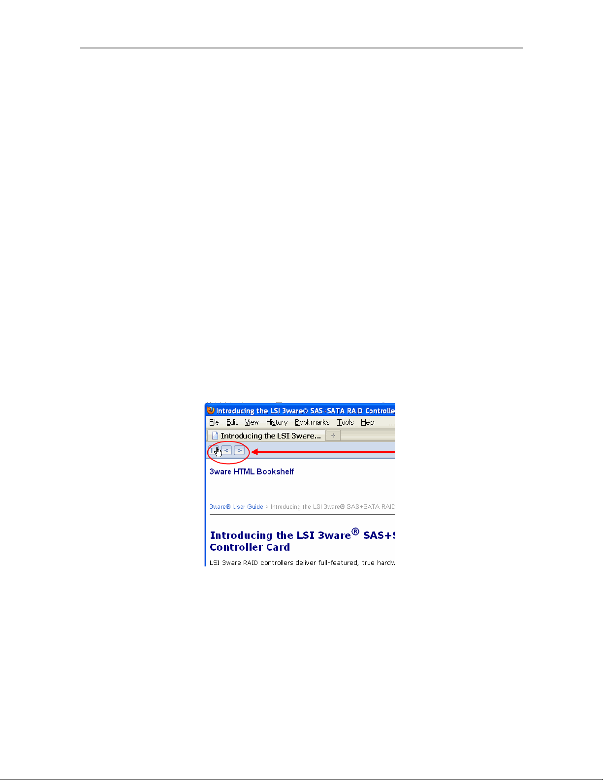
You can also open the bookshelf by double-clicking any HTML file in the
3ware HTMLBookshelf folder. When you open an individual file, the
navigation pane does not automatically open. In this case, you can view
the navigation pane by clicking the
Figure 1. Navigation Button in the 3ware HTML Bookshelf Window
Show Navigation button at the left.
www.lsi.com/channel/products xi
Page 12
Note: The 3ware HTML Bookshelf is created as a set of HTML documents
that are often displayed from a website. When installed on your personal
computer, some browsers flag them as “active content,” and require your
approval before displaying the content.
If you see messages similar to the following, you must confirm the display of
active content in order to see the pages.
xii 3ware SATA+SAS RAID Controller Card Software User Guide, Version 10.2
Page 13

Introducing the LSI 3ware SATA+SAS RAID Controller Card
LSI 3ware RAID controllers deliver full-featured, true hardware RAID to
servers and workstations. 3ware RAID controllers offer Serial Attached SCSI
(SAS) and Serial ATA (SATA) interfaces. Combined with an advanced RAID
management feature-set that includes web-based, command-based, and API
(application programming interface) software components, LSI RAID
controllers provide compelling RAID solutions.
This section introduces the features and concepts of 3ware RAID controllers.
It is organized into the following topics:
1
• What’s New for the 10.2 Release
• Highlights of the 10.2 Release
• System Requirements
• Understanding RAID Concepts and Levels
• 3ware Tools for Configuration and Management
• Monitoring, Maintenance, and Troubleshooting Features
What’s New for the 10.2 Release
Version 10.2 of the 3ware RAID software and firmware has the following new
features and benefits to the 3ware 9750 model RAID controllers.
• Added external enclosure support with the following new 3ware
controllers: 9750-4i4e, 9750-8e, 9750-16i4e, 9750-24i4e.
• Added ability to upgrade storage enclosure processor (SEP) firmware.
Refer to the 3ware SA TA+SAS RAID Controller Card CLI Guide, Version
10.2 for more information.
• Added support for the latest FreeBSD and Linux distributions. For details,
refer to the release notes at
http://www.lsi.com/channel/ChannelDownloads
www.lsi.com/channel/products 1
Page 14

Chapter 1. Introducing the LSI 3ware SATA+SAS RAID Controller Card
• Updated 3ware firmware.
• Updated 3DM2 and CLI software.
• Updated Windows drivers.
Highlights of the 10.2 Release
Version 10.2 of the 3ware RAID Software and Firmware provides the
following features and benefits to the 3ware 9750 model RAID controllers.
• Support for 6 Gbps SATA+SAS RAID On-a-Chip devices available on
the 3ware 9750 RAID controllers, with continued support for the 3ware
RAID software feature-set.
• Read cache settings let you enable either Basic Read Caching or
Intelligent Read Caching to improve performance.
• Background task mode provides low latency settings to improve
performance in video and audio applications.
• Enclosure alarm support allows you to turn off or mute audible alarms in
supported enclosures that provide alarms.
• Advanced Content Streaming, a performance feature, provides increased
speeds for streamed data, such as video playback and editing, through
improved algorithms.
• Rapid RAID Recovery increases the speed with which a degraded unit
can be rebuilt. It can also increase the speed of verification or
initialization that may occur in the event of an unclean shutdown.
• Improved and simplified auto-verification and scheduling to help ensure
that your RAID units are verified on a regular basis.
• Drive performance monitoring provides statistics to help trouble-shoot
performance issues.
• Simultaneous RAID 6 parity generation to maximize RAID 6
performance.
• StreamFusion™+ optimizes RAID 5 and RAID 6 disk accesses to
maximize application performance under heavy loads.
• StorSave™ BBU with write journaling optimizes data protection and
performance.
• Hot-swap and hot-spare for data availability.
• RAID levels 0, 1, 5, 6, 10, 50, and Single Disk.
• With the 9750 models:
• PCI Express
• Ability to have SAS and/or SATA drives on the same controller (see
“Drive Requirements” on page 3)
2 3ware SATA+SAS RAID Controller Card Software User Guide, Version 10.2
®
x8 Gen 2.0
Page 15

• Connectivity with up to 127 single-ported drives or 62 dual-ported
drives when using cascaded chassis that use expanders of the same
type. (see “Enclosure Management Requirements” on pa ge 4)
• Up to 32 drives in a unit
• Up to 32 active units
• Operating system support for Windows, Lin ux, FreeBSD, Mac OS X,
OpenSolaris, and VMware.
System Requirements
This section describes the requirements for the 3ware 9750 model RAID
controllers:
Motherboard and Slot Requirements
The 3ware 9750 RAID controller uses workstation-class or server-class
motherboards, with an available PCI Express x8 or x16 slot that complies
with PCIe Gen 2.0 (recommended for best performance) or PCIe 1.1.
System Requirements
A list of motherboards that have been tested is available at
http://www.lsi.com/channel/support/marketing_resources, through the Data &
Interoperability tab.
Drive Requirements
The 3ware 9750 RAID controller may be connected to up to 62 SAS and/or
SATA dual-ported drives, or 127 SAS and/or SATA single-ported drives,
when using one or more enclosures. A maximum of 32 drives are allowed per
RAID unit and up to 32 active RAID units per controller.
3ware 9750 RAID controller is designed for use with drive capacities up to
2TB and over.
You cannot mix SAS and SATA drives in the same unit.
A mix of 3 Gbps and 6 Gbps hard drives are allowed.
Drives and drive enclosures must meet SAS or SATA (3.0 Gbps and
6.0 Gbps) standards.
A list of drives that have been tested is available at
http://www.lsi.com/channel/support/marketing_resources, through the Data &
Interoperability tab.
Drives may be of any capacity or physical form factor.
The length of internal unshielded interface cables may not exceed 1 meter
(39 inches).
The length of external cables for SAS 1.1 at 3 Gpbs supports lengths of up to
8 meters and for SAS 2.0 at 6 Gpbs supports external cable length to
10 meters.
www.lsi.com/channel/products 3
Page 16

Chapter 1. Introducing the LSI 3ware SATA+SAS RAID Controller Card
Enclosure Management Requirements
For 9750 RAID controllers and release 10.2, enclosure management features
in 3ware software are available for supported chassis that provide SCSI
Enclosure Services 2 (SES-2) through an internal sideband connection, or via
an expander.
When chassis enclosures are cascaded, expanders of the same type are
recommended. A limit of 4 cascaded expanders is supported.
Chassis and enclosures may be cascaded up to 4 deep, per wide port.
Must support both SAS1 and SAS2, and desirable to allow both within the
same domain.
CLI supports in-band firmware downloads to the enclosure processor.
A list of supported enclosures is available at
http://www.lsi.com/channel/support/marketing_resources, through the Data &
Interoperability tab.
Operating System
3ware 9750 RAID controllers may be used with the following operating
systems for Intel and AMD 32-bit and 64-bit x86 based motherboards:
• Microsoft Windows Server 2003 (SP2 or newer) and 2008
• Microsoft Windows Vista and Windows 7
• Red Hat Enterprise Linux
®
• openSUSE® Linux
®
• SUSE
Linux Enterprise Server
• Fedora Core Linux
• Other Linux distributions based on open source Linux 2.6 kernel
• VMware
• OpenSolaris
• FreeBSD
• Mac OS X (Intel only)
For the latest supported operating systems, see the current Release Notes at
http://www.lsi.com/channel/ChannelDownloads or the file versions.txt,
available on the 3ware CD.
Other Requirements
• Adequate air flow and cooling
• Adequate power supply for drives
• 3DM2 (3ware Disk Manager 2) displays information in a browser. It
requires one of the following browsers:
4 3ware SATA+SAS RAID Controller Card Software User Guide, Version 10.2
Page 17

Understanding RAID Concepts and Levels
• Internet Explorer® (current version)
• Mozilla Firefox
®
• Safari
In addition:
• JavaScript must be enabled.
• Cookies must be enabled.
• For best viewing, screen resolution should be 1024 x 768 or greater,
with 16-bit color or greater.
For a complete listing of features and system requirements, refer to the 3ware
SATA+SAS RAID Controller datasheets, available from the website at
http://www.lsi.com/channel/products/megaraid/sassata/index.html.
(current version)
®
(current version)
Understanding RAID Concepts and Levels
3ware RAID controllers use RAID (Redundant Array of Independent Disks)
to increase your storage system’s performance and provide fault tolerance
(protection against data loss).
This section includes the following RAID-specific topics:
• “RAID Concepts”
• “Available RAID Configurations” on page 6
• “Determining Which RAID Level to Use” on page 12
RAID Concepts
The following concepts are important to understand when working with a
RAID controller:
•
•
Arrays and Units. In the storage industry, an array refers to two or more
disk drives that appear to the operating system as a single unit. When
working with a RAID controller, unit refers to an array of disks that you
can configured and manage through the 3ware software. You can also use
the 3ware software to configure Single-disk units.
Mirroring. Mirrored arrays (RAID 1) write data to paired drives
simultaneously . If one drive fails, the data is preserved on the paired
drive. Mirroring provides data protection through redundancy. In
addition, mirroring using a 3ware RAID controller provides improved
performance because the 3ware TwinStor® technology reads from both
drives simultaneously.
Striping. Striping across disks allows data to be written and accessed on
•
more than one drive simultaneously. Striping combines each drive’s
www.lsi.com/channel/products 5
Page 18

Chapter 1. Introducing the LSI 3ware SATA+SAS RAID Controller Card
capacity into one large volume. Striped disk arrays (RAID 0) achieve
highest transfer rates and performance at the expense of fault tolerance.
Distributed Parity . Parity works in combination with striping on RAID 5,
•
RAID 6, and RAID 50. Parity information is written to each of the striped
drives, in rotation. If a failure occurs, you can reconstructed the data on
the failed drive from the data on the other drives.
•
Hot Swap. The process of exchanging a drive without shutting down the
system. This process is useful when you need to exchange a defective
drive in a redundant unit.
•
Array Roaming. The process of from a controller and putting it back
either on the same controller, or a different controller, and having the unit
recognized as a unit. You can attach the disks to different ports without
harm to the data.
Available RAID Configurations
RAID is a method of combining several hard drives into one unit. It can offer
fault tolerance and higher throughput levels than a single hard drive or group
of independent hard drives. LSI's 3ware controllers support RAID 0, 1, 5, 6,
10, 50, and Single Disk. The following information explains the different
RAID levels.
RAID 0
RAID 0 provides improved performance, but no fault tolerance. Because the
data is striped across more than one disk, RAID 0 disk arrays achieve high
transfer rates because they can read and write data on more than one drive
simultaneously. You can configure the stripe size during unit creation.
RAID 0 requires a minimum of two drives.
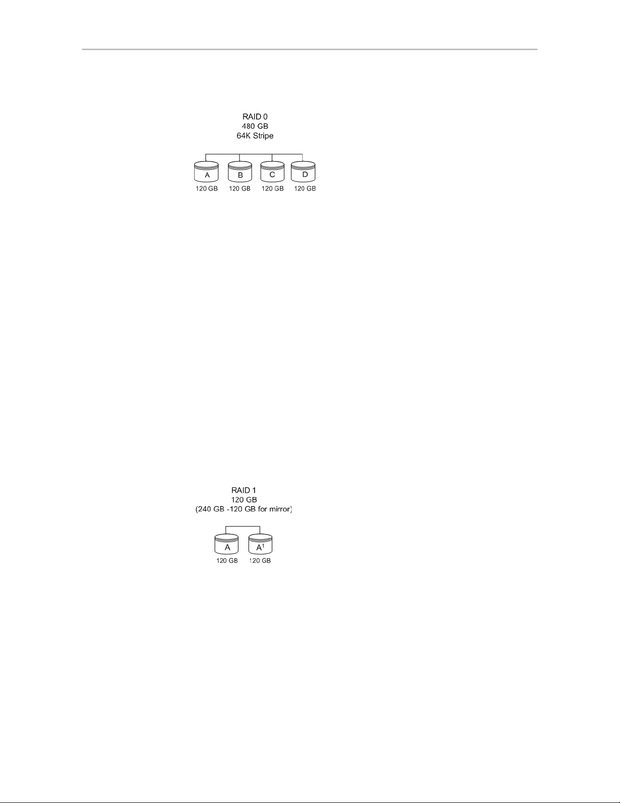
When drives are configured in a striped disk array (see Figure 2), large files
are distributed across the multiple disks using RAID 0 techniques.
Striped disk arrays give exceptional performance, particularly for dataintensive applications such as video editing, computer-aided design, and
geographical information systems.
RAID 0 arrays are not fault tolerant. The loss of any drive results in the loss of
all the data in that array, and can even cause a system hang, depending on
your operating system. RAID 0 arrays are not recommended for highavailability systems unless you take additional precautions to prevent system
hangs and data loss.
6 3ware SATA+SAS RAID Controller Card Software User Guide, Version 10.2
Page 19
Understanding RAID Concepts and Levels
Figure 2. RAID 0 Configuration Example
RAID 1
RAID 1 provides fault tolerance and a speed advantage over non-RAID disks.
RAID 1 also is known as a mirrored array. Mirroring is done on pairs of
drives. Mirrored disk arrays write the same data to two different drives using
RAID 1 algorithms (see Figure 3). This gives your system fault tolerance by
preserving the data on one drive if the other drive fails. Fault tolerance is a
basic requirement for critical systems should as web and database servers.
3ware firmware uses a patented TwinStor technology, on RAID 1 arrays for
improved performance during sequential read operations. With TwinStor
technology, read performance during a sequential read operation is twice the
speed of a single drive.
The adaptive algorithms in TwinStor technology boost performance by
distinguishing between random read request and sequential read requests. For
the sequential read requests generated when accessing large files, both drives
are used with the drive heads simultaneously reading alternating sections of
the file. For the smaller random transactions, the data is read by a single
optimal drive head.
Figure 3. RAID 1 Configuration Example
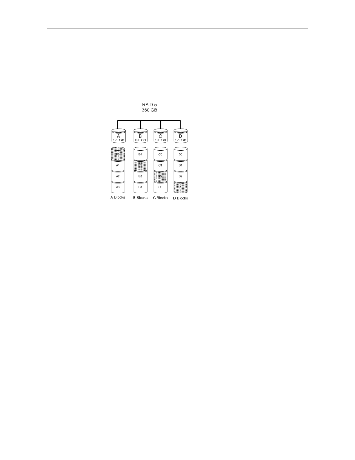
RAID 5
RAID 5 provides performance, fault tolerance, high capacity, and storage
efficiency. It requires a minimum of three drives and combines striping data
with parity (exclusive OR) to restore data in case of a drive failure.
Performance and efficiency increase as the number of drives in a unit
increases.
www.lsi.com/channel/products 7
Page 20
Chapter 1. Introducing the LSI 3ware SATA+SAS RAID Controller Card
(480 GB - 120 GB for parity)
Parity information is distributed across all of the drives in a unit rather than
being concentrated on a single disk (see Figure 4). This method avoids
throughput loss due to contention for the parity drive.
RAID 5 can tolerate one drive failure in the unit.
Figure 4. RAID 5 Configuration Example
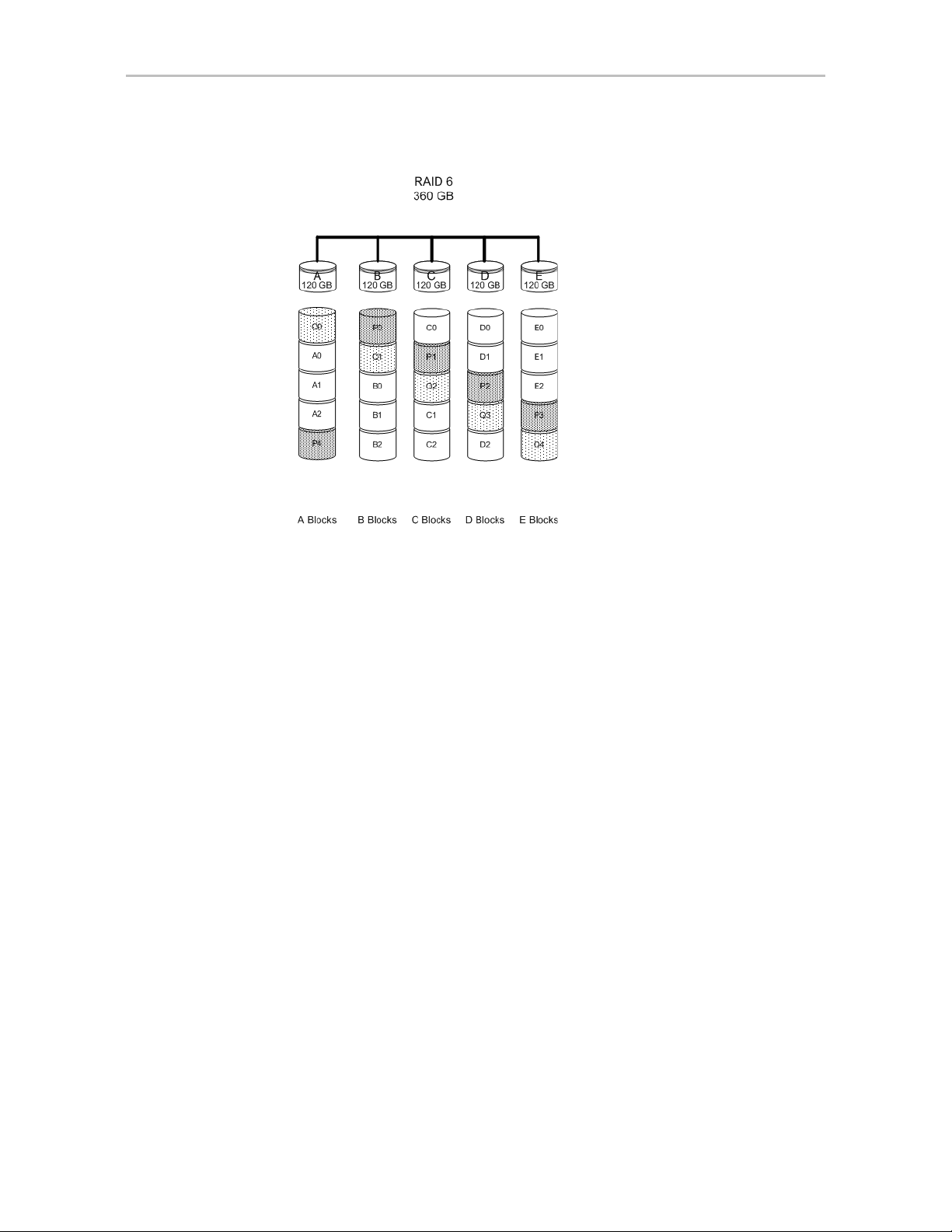
RAID 6
RAID 6 provides greater redundancy and fault tolerance than RAID 5. It is
similar to RAID 5 but, instead of a single block, RAID 6 has two blocks of
parity information (P+Q) distributed across all the drives of a unit (see
Figure 5).
Due to the two parities, a RAID 6 unit can tolerate two hard drives failing
simultaneously. This also means that a RAID 6 unit can be in two different
states at the same time. For example, one subunit can be degraded while
another is rebuilding, or one subunit can be initializing while another is
verifying.
The 3ware implementation of RAID 6 requires a minimum of five drives.
Performance and storage efficiency also increase as the number of drives
increase.
8 3ware SATA+SAS RAID Controller Card Software User Guide, Version 10.2
Page 21
Understanding RAID Concepts and Levels
(600 GB - 240 GB for 2 parity drives)
Figure 5. RAID 6 Configuration Example
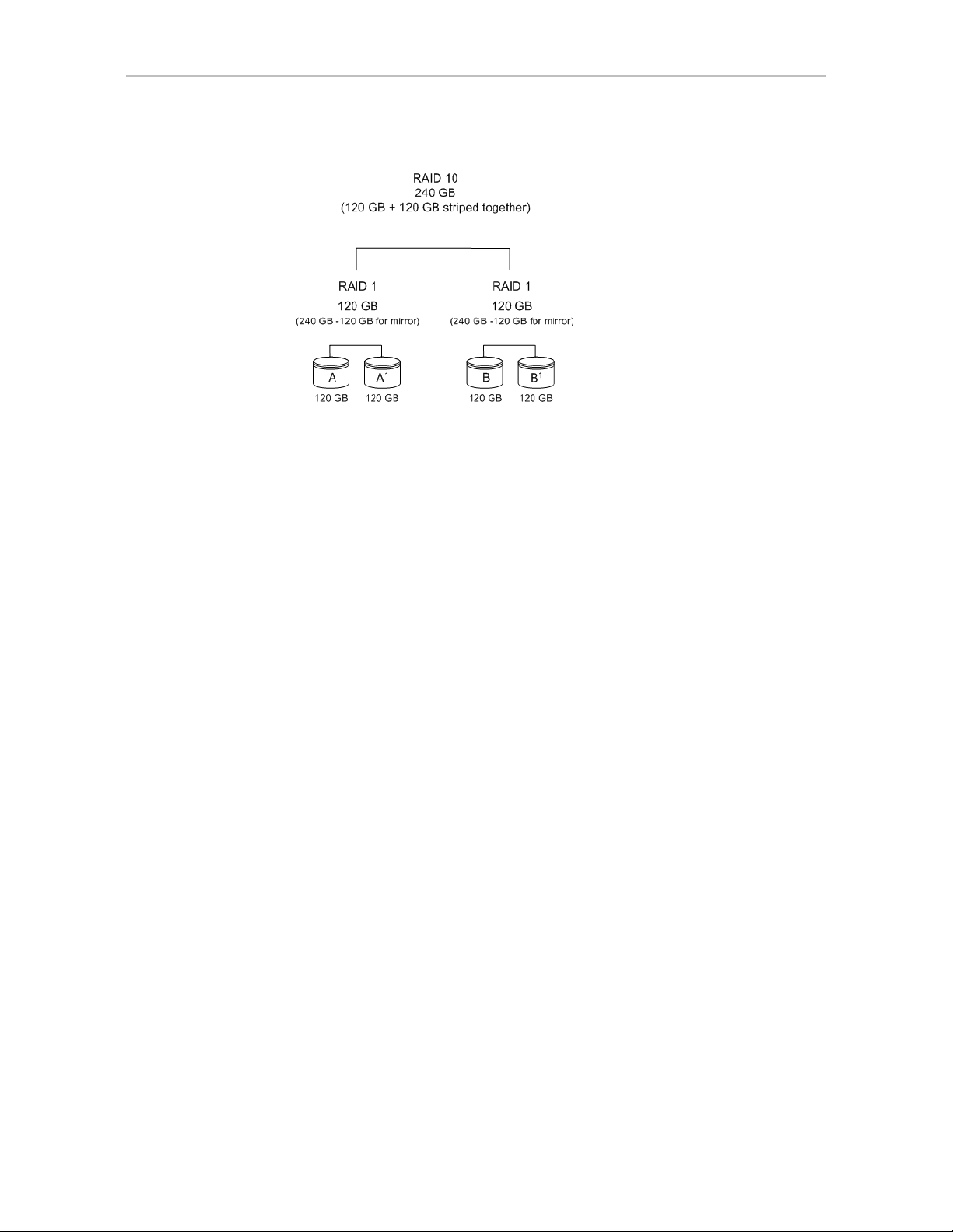
RAID 10
RAID 10 is a combination of striped and mirrored arrays for fault tolerance
and high performance.
When drives are configured as a striped mirrored array, the disks are
configured using both RAID 0 and RAID 1 techniques (see Figure 6). A
minimum of four drives are required to use this technique. The first two drives
are mirrored as a fault-tolerant array using RAID 1. The third and fourth
drives are mirrored as a second fault-tolerant array using RAID 1. The two
mirrored arrays are then grouped as a striped RAID 0 array using a two-tier
structure. Higher data transfer rates are achieved by leveraging TwinStor
technology and striping the arrays.
In addition, RAID 10 arrays offer a higher degree of fault tolerance than
RAID 1 and RAID 5 because the array can sustain multiple drive failures
without data loss. For example, in a 12-drive RAID 10 array, up to 6 drives
can fail (half of each mirrored pair) and the array continues to function. Note
that if both halves of a mirrored pair in the RAID 10 array fail, all of the data
is lost.
www.lsi.com/channel/products 9
Page 22
Chapter 1. Introducing the LSI 3ware SATA+SAS RAID Controller Card
Figure 6. RAID 10 Configuration Example
RAID 50
RAID 50 is a combination of RAID 5 and RAID 0. This array type provides
fault tolerance and high performance. RAID 50 requires a minimum of six
drives.
Several combinations are available with RAID 50. For example, on a 12-port
controller, you can have a grouping of three, four, or six drives. A grouping of
three means that the RAID 5 arrays used have three disks each; four of these
3-drive RAID 5 arrays are striped together to form the 12-drive RAID 50
array . On a 16-port controller, you can have a grouping of four or eight drives.
No more than four RAID 5 subunits are allowed in a RAID 50 unit. For
example, a 24-drive RAID 50 unit may have groups of 12, eight, or six drives,
but not groups of four or three (see Figure 7).
In addition, RAID 50 arrays offer a higher degree of fault tolerance than
RAID 1 and RAID 5, because the array can sustain multiple drive failures
without data loss. For example, in a 12-drive RAID 50 array , one drive in each
RAID 5 set can fail and the array continues to function. Note that if two or
more drives in a RAID 5 set fail, all of the data is lost.
10 3ware SATA+SAS RAID Controller Card Software User Guide, Version 10.2
Page 23

Understanding RAID Concepts and Levels
(600 GB - 120 GB for parity)
(600 GB - 120 GB for parity)
(960 GB - 480 GB for mirror)
Figure 7. RAID 50 Configuration Example
Single Disk
You can configure a single drive as a unit through 3ware software. (3BM,
3DM2, or CLI).
Similar to disks in other RAID configurations, single disks contain 3ware
Disk Control Block (DCB) information and the OS addresses them as
available units.
Single drives are not fault tolerant and, therefore, are not recommended for
high availability systems unless you take additional precautions to prevent
system hangs and data loss.
Hot Spare
A hot spare is a single drive, available online, so that a redundant unit is
automatically rebuilt without human intervention in case of drive failure.
www.lsi.com/channel/products 11
Page 24
Chapter 1. Introducing the LSI 3ware SATA+SAS RAID Controller Card
Determining Which RAID Level to Use
The type of RAID unit (array) that you create depends on your needs. You
might want to maximize speed of access, total amount of storage, or
redundant protection of data. Each type of RAID unit offers a different blend
of these characteristics.
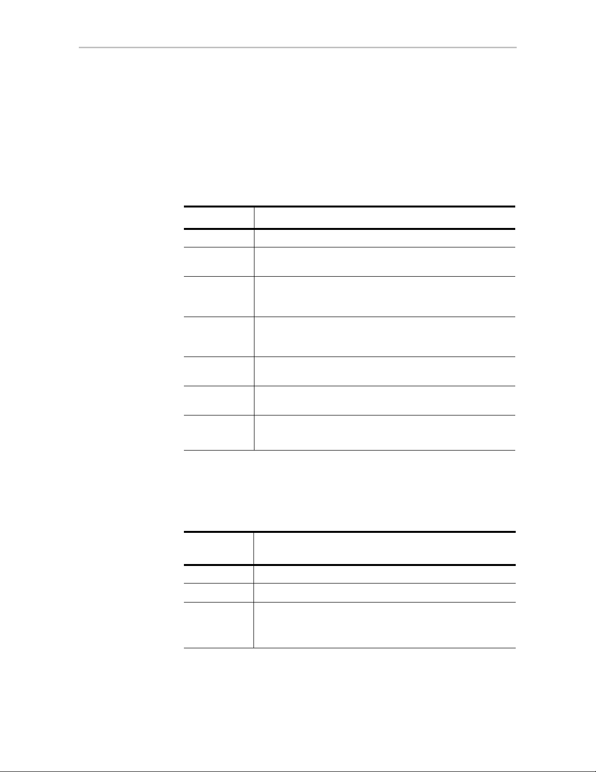
The following table summarizes RAID configuration types.
Table 2: RAID Configuration Types
RAID Type Description
RAID 0 Provides performance, but no fault tolerance.
RAID 1 Provides fault tolerance and a read speed advantage over non-
RAID disks.
RAID 5 Provide s performance, fault tolerance, and high storage
efficiency. RAID 5 units can tolerate one drive failing before
losing data.
RAID 6 Provides very high fault tolerance with the ability to protect
against two consecutive drive failures. Performance and
efficiency increase with higher numbers of drives.
RAID 10 Provides a combination of striped and mirrored units for fault
tolerance and high performance.
RAID 50 Provides a combination of RAID 5 and RAID 0. RAID 50 provides
high fault tolerance and performance.
Single Disk Not a RAID type - but supported as a configuration.
Provides maximum disk capacity with no redundancy.
You can create one or more units, depending on the number of drives you
install. The following table provides possible configurations based on your
number of drives.
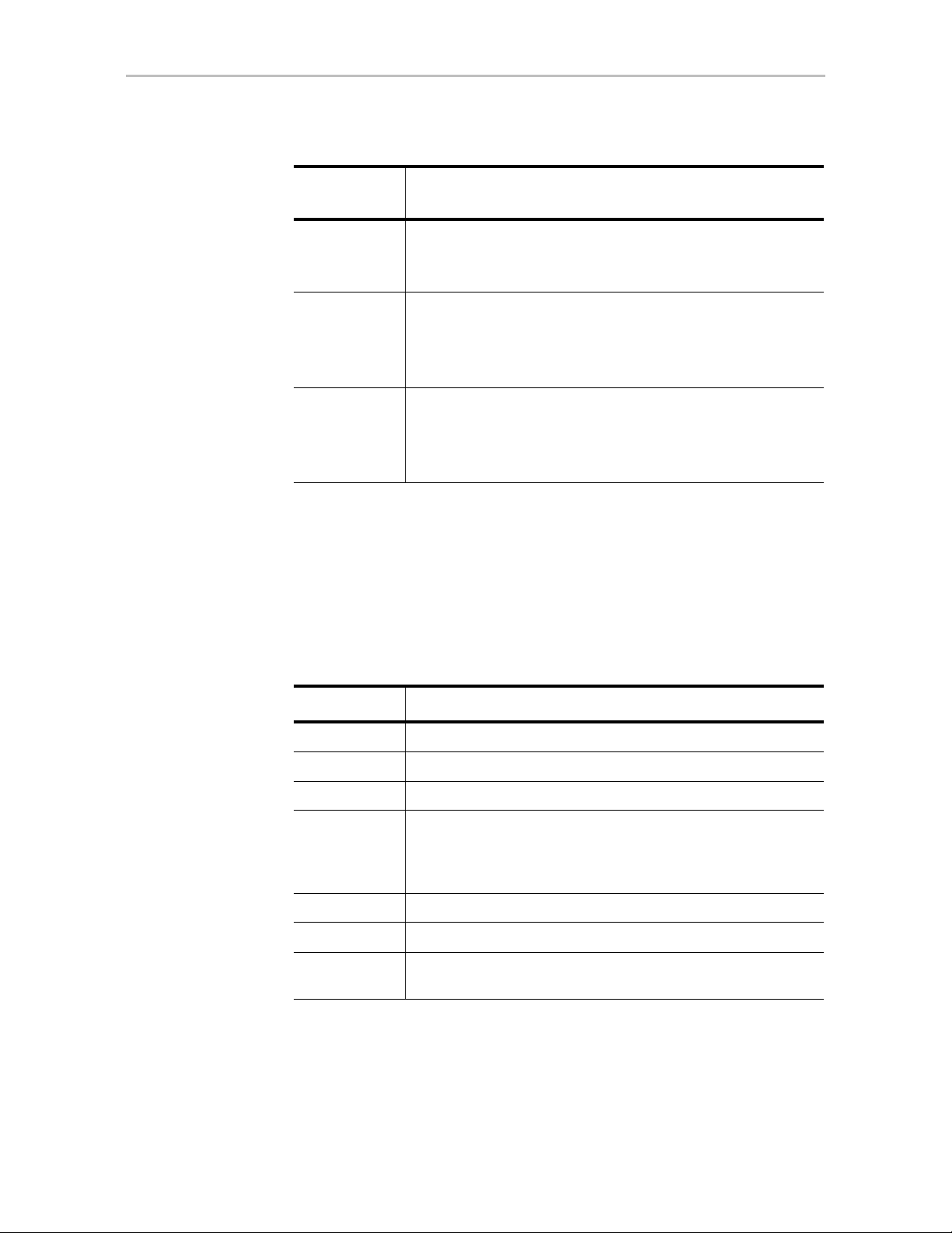
Table 3: Possible Configurations Based on Number of Drives
Number of
Drives
1 Single disk
2 RAID 0 or RAID 1
Possible RAID Configurations
3RAID 0
RAID 1 with hot spare
RAID 5
12 3ware SATA+SAS RAID Controller Card Software User Guide, Version 10.2
Page 25
Understanding RAID Concepts and Levels
Table 3: Possible Configurations Based on Number of Drives
Number of
Drives
4 RAID 5 with hot spare
5RAID 6
6 or more RAID 6
Possible RAID Configurations
RAID 10
Combination of RAID 0, RAID 1, single disk
RAID 5 with hot spare
RAID 10 with hot spare
Combination of RAID 0, RAID 1, hot spare, single disk
RAID 6 with hot spare
RAID 50
Combination of RAID 0, 1, 5, 6,10, hot spare, single disk
Using Drive Capacity Efficiently
Because the capacity of each drive is limited to the capacity of the smallest
drive in the unit, use drives of the same capacity in a unit.
The total unit capacity is defined as follows:
Table 4: Drive Capacity
RAID Level Capacity
Single Disk Capacity of the drive
RAID 0 (number of drives) X (capacity of the smallest drive)
RAID 1 Capacity of the smallest drive
RAID 5 (number of drives – 1) X (capacity of the smallest drive)
Storage efficiency increases with the number of disks:
storage efficiency = (number of drives – 1)/(number of drives)
RAID 6 (number of drives – 2) x (capacity of the smallest drive)
RAID 10 (number of drives/2) X (capacity of smallest drive)
RAID 50 (number of drives – number of groups of drives) X (capacity of
the smallest drive)
Through drive coercion, the capacity used for each drive is rounded down to
improve the likelihood that you can use drives from differing manufactures as
spares for each other. The capacity used for each drive is rounded down to the
www.lsi.com/channel/products 13
Page 26
Chapter 1. Introducing the LSI 3ware SATA+SAS RAID Controller Card
nearest GB for drives under 45 GB (45,000,000,000 bytes), and rounded
down to the nearest 5 GB for drives over 45 GB. For example, a 44.3-GB
drive is rounded down to 44 GB, and a 123-GB drive is rounded down to
120 GB.
Note: All drives in a unit must be of the same type, either SAS or SATA.
3ware Tools for Configuration and Management
3ware software tools let you easily configure the drives attached to your
3ware RAID controller, specifying which drives you should use together as a
RAID unit and the type of RAID configuration that you want, and designating
hot spares for use if a drive degrades.
3ware provides the following tools for use in configuring and managing units
attached to the 3ware controller:
• 3BM (3ware BIOS Manager)
3BM is a BIOS-level tool available on PC-based systems that you can use
to create, delete, and maintain disk arrays, rebuild arrays, designate hot
spares, and set controller policies. 3BM is the tool most frequently used to
configure units immediately after installation of the controller, but also
can be used after installation to maintain the controller and associated
drives. (3BM is not available for Mac OS X.)
For general information about working with 3BM, see Chapter 4, “3ware
BIOS Manager (3BM) Introduction.”
• 3DM2 (3ware Disk Manager)
3DM2 provides browser-based software that you can use to create, delete,
and maintain disk arrays, rebuild arrays, designate hot spares, and set
controller policies. 3DM2 is a daemon (under FreeBSD, Linux,
Mac OS X, OpenSolaris, and VMware) and a service (under Windows)
that runs in the background on the controller’s host system. You can
access 3DM2 through a web browser to provide ongoing monitoring and
administration of the controller and associated drives. You can use 3DM2
locally (on the system that contains the 9750) or remotely (on a system
connected via a network to the system containing the 9750).
For details about working with the 3ware Disk Manager 2, see
“3DM2 (3ware Disk Manager 2) Introduction” on page 44.
14 3ware SATA+SAS RAID Controller Card Software User Guide, Version 10.2
Page 27

Monitoring, Maintenance, and Troub leshooting Features
3DM2 is the current version of the 3ware Disk Manager. Throu ghout thi s
documentation, it is referred to interchangeably as 3DM and 3DM2.
• 3ware Alert Utility (WinAVAlarm)
The 3ware Alert Utility for Windows runs on the system in which the
3ware RAID controller is installed and provides direct notification by a
pop-up message and audio alarm when events occur. You can configure
this unit to specify the type of events that should generate these
notifications. For details, see “Using the Alert Utility Under W indows” on
page 142.
• 3ware CLI (Command Line Interface)
The 3ware CLI provides the functionality available in 3DM2 through a
command line interface. CLI also provides advanced functions not
included in 3DM2 such as, drive performance monitoring (DPM). You
can view unit status and version information and perform maintenanc e
functions such as adding or removing drives, and reconfiguring RAID
units online. You also can use it to remotely administer controllers in a
system.
The 3ware CLI is described in 3ware SATA+SAS RAID Controller Card
CLI Guide, Version 10.2 and in the 3ware HTML Bookshelf.
Monitoring, Maintenance, and
Troubleshooting Features
Several 3ware RAID controller features aid in monitoring and
troubleshooting your drives.
•
Auto-Rebuild. When you do not have a spare available, setting the Auto
Rebuild policy allows rebuilds to occur with an available drive or with a
failed drive. (For more information, see “Setting the Auto-Rebuild
Policy” on page 71.)
Drive Performance Monitoring (DPM). DPM is an advanced trouble-
•
shooting tool used to measure drive performance, and to help identify
when a specific drive is causing problems so that you can repair or replace
it. Commands are available through the 3ware CLI to enable and disable
DPM, and to see a range of different statistics. These statistics can be
useful to help troubleshoot problems with your RAID controller and
units. For more information, see “Drive Performance Monitoring” on
page 229.
•
Enclosure Services. Drives, fans, temperature sensors, and power
supplies in supported chassis and enclosures can be identified by flashing
LEDs so that you can quickly identify which component needs to be
checked or replaced. For more information, see “Enclosure Management”
on page 179.
www.lsi.com/channel/products 15
Page 28

Chapter 1. Introducing the LSI 3ware SATA+SAS RAID Controller Card
• Error Correction. Bad sectors can be dynamically repaired through error
correction (Dynamic Sector Repair). Reallocation of blocks is based
intelligently on the location of the block in relation to the stripe.
•
Scheduled Background Tasks. Initialize, rebuild, verify, and self-test
tasks can all be run in the background, at scheduled times. This task lets
you choose a time for these tasks to be run when it will be least disruptive
to your system. You also can define the rate at which background tasks
are performed, specifying whether I/O tasks should be given more
processing time, or background rebuild and verify tasks should be given
more processing time. (For more information, see “Scheduling
Background Tasks” on page 163.)
•
SMART Monitoring. Self-Monitoring, Analysis and Reporting
T echnology (SMART) automatically checks the health of SA TA and SAS
disk drives every 24 hours and reports potential problems. This allows
you to take proactive steps to prevent impending disk crashes. SMART
data is checked on all disk drives (array members, single disks, and hot
spares). Monitoring of SMART thresholds can be turned on and off in
3DM2. For more information, see “Selecting Self-tests to be Performed”
on page 168 and “Viewing SMART Data About a Drive” on page 144.
•
Staggered Spinup. Staggered spinup allows drives that support this
feature to be powered-up into the standby power management state to
minimize in-rush current at power-up and to allow the controller to
sequence the spin-up of drives. Both SATA-2 OOB and ATA spin-up
methods are supported. The standby power management state is persistent
after power-down and power-up. You can set the number of drives that
will spin up at the same time, and the time between staggers in 3BM and
CLI. For more details, see T able 5 on page 32.
This feature does not apply
to drives that are attached to an expander. For details, see “Enabling and
Setting Up Staggered Spin-up” on page 74.
StorSave™ Profiles allow you to set the level of protection versus
•
performance that is desired for a unit when write cache is enabled. (For
more information, see “Setting the StorSave Profile for a Unit” on
page 111.)
•
Verification and Media Scans. The verify task verifies all redundant
units, and checks for media errors on single disks, spares and RAID 0 unit
members. If the disk drive is part of a redundant unit, error locations that
are found and are deemed repairable are rewritten with the redundant
data. This forces the drive firmware to reallocate the error sectors
accordingly. (For more information, see “About Verification” on
page 149.)
•
Read Cache. Two read cache settings are available. Basic Read Cache
stores data from media locally on the controller to improve read access
times for applications. The 3ware Read Cache feature also includes an
Intelligent Mode, which enables intelligent read prefetch (IRP). IRP
16 3ware SATA+SAS RAID Controller Card Software User Guide, Version 10.2
Page 29

Monitoring, Maintenance, and Troub leshooting Features
includes a typical read-ahead caching method which is used to proactively
retrieve data from media and store it locally on the controller with the
anticipation that it may be requested by the host. By default read cache is
set to the Intelligent mode. For more information, see “Working with
Read Cache Settings” on page 104.
Write Cache. You can en able or disable write cache using 3BM, 3DM2,
•
and CLI. When write cache is enabled, data will be stored in 3ware
controller cache and drive cache before the data is committed to disk.
This allows the system to process multiple write commands at the same
time, thus improving performance. However when data is stored in cache,
it could be lost if a power failure occurs. With a battery backup unit
(BBU) installed, the data stored on the 3ware controller can be restored.
(For more information, see “Enabling and Disabling the Unit Write
Cache” on page 102.
www.lsi.com/channel/products 17
Page 30
2
First-Time RAID Configuration Using 3BM
If you are installing the operating system on and boot from a unit managed
through the new 3ware RAID controller, follow the steps in this chapter to use
the 3ware BIOS Manager (3BM) to configure the unit and install the driver.
Mac User Note: The 3ware BIOS Manager (3BM) is not supported for Mac OS X.
Mac OS users, skip this chapter.
If the operating system is already installed on another drive in your system,
you can use the steps below or you can configure units through 3DM2 or the
CLI.
You can create one or more units on a single controller, depending on the
number of drives that the specific 3ware RAID controller supports and the
number of drives attached. (For more information, see “Determining Which
RAID Level to Use” on page 12.)
Basic Steps for Creating a Unit
Configuring your RAID units includes these main steps.
• Launch 3BM (3ware BIOS Manager)
• Select the drives to be included and indicate that you want to create a unit
• Select the desired RAID configuration
• Set other parameters, depending on the type of RAID configuration
• Confirm the unit configuration
• Save your changes and finish up
Launching 3BM
1 Power up or reboot your system.
While the system is starting, watch for a screen similar to Figure 8.
18 3ware SATA+SAS RAID Controller Card Software User Guide, Version 10.2
Page 31

Basic Steps fo r Creating a Unit
----Press <Alt-3> to access 3ware BIOS Manager ---3ware ATA RAID Controller: 9750-4I
BIOS: BE9X X.XX.XX.XXX Firmware: FE9X X.XX.XX.XXX
BBU Status: Not Present
Number of online units: 1, available drives: 0, hot spare: 0, offline units:0
Available drives:
SATA - SAMSUNG HD160JJ 149.04 GB Phy 0
Exportable Units:Œ
3drive 64K RAID5 298.00 GB (Zygote3) DEGRADED
SATA - SAMSUNG HD160JJ 149.04 GB (Phy 3)
SATA - SAMSUNG HD160JJ 149.04 GB (Phy 1)
Figure 8. 3ware BIOS Screen
2 Press Alt-3 or 3 immediately to bring up the 3ware BIOS Manager
(3BM).
Normally your 3ware configuration remains on-screen for just a few
seconds. However, if a unit has degraded, the screen indicates the
problem and remains on your screen longer.
3 If you plan to make changes to your config uration and need to backup
data before continuing, press ESC and do so now. Otherwise, press any
key to continue.
Figure 9. Warning Message When you Start 3BM
4 If you have more than one 9750 co ntroller in your system, a screen lists
the available boards. (See Figure 10.) In this case, highlight the board
with which you want to work and press Enter.
If you have more than four boards, you see only four at first (only four
can be processed at a time). After you exit from 3BM, you can access the
BIOS again, and access the next boards.
www.lsi.com/channel/products 19
Page 32

Chapter 2. First-Time RAID Configuration Using 3BM
Figure 10. 3ware Controller Board Selection Screen
A screen similar to Figure 9 appears, warning you that changing your disk
array configuration may overwrite data on the disks.
To select the drives and create a unit
1 Select the drives to be included by highlighting each one and pressing
Enter to select it, or select all at once by selecting the heading above
them.
When you select a drive, an asterisk appears next to it in the left-most
column (see Figure 11).
You may include from 1 to 32 drives in the unit, depending on the number
available.
Figure 11. Asterisks Next to Selected Drives
2 After all drives for the unit are selected, use the Tab to move to the
Create Unit button and press Enter.
The Create Disk Array screen appears (see Figure 12).
20 3ware SATA+SAS RAID Controller Card Software User Guide, Version 10.2
Page 33

Basic Steps fo r Creating a Unit
3 Make sure that the proper drives are listed.
Figure 12. Create Disk Array screen
To name the unit and select the desired RAID configuration
1 (Optional) Press Enter in the Array Name field and type a name for the
unit. Then press Enter again to accept the name.
2 Use the arrow keys or press Tab to move to the RAID Configuration
field and press Enter to view the available RAID levels for the number of
drives you selected.
Figure 13. List of Configuration Choices for Four Drives
3 Use the arrow keys to highlight the desired RAID configuration and
press Enter.
For information about the different RAID levels and when to use each,
see “Understanding RAID Concepts and Levels” on page 5.
4 Use the arrow keys or press Tab to move to the field Stripe Size and
select the desired stripe size (16KB, 64KB, or 256KB).
Notes:
Striping size is not applicable for RAID 1, because it is a mirrored unit
without striping.
For RAID 6, only stripe sizes of 64 KB and 256 KB are supported.
www.lsi.com/channel/products 21
Page 34

Chapter 2. First-Time RAID Configuration Using 3BM
To set other policies for the unit
While creating a unit through 3BM, you can set a number of unit policies.
Each of these policies is already set to a default value, so you do not have to
change them.
Many of these options are listed on the Create Disk Array screen. A few are
available through the Advanced Options screen.
1 Use the arrow keys to move through the policies shown on the screen,
select the option you want and press Enter to choose it.
2 Press
Tab to the Advanced button and press Enter to open the Advanced
options screen, where additional policies are available.
For details about the various unit policies, see the following sections:
• “Enabling and Disabling the Unit Write Cache” on page 102
• “Working with Read Cache Settings” on page 104
• “Setting the StorSave Profile for a Unit” on page 111
• “Enabling or Disabling Auto-Verify for a Unit” on page 107
• “Rapid RAID Recovery” on page 113
• “Enabling and Disabling Queuing for a Unit” on page 110
• “Setting Overwrite ECC (Continue on Source Error When Rebuilding)”
on page 108
• “Initialization Method” on page 81
Figure 14. Create Disk Array Advanced Options screen
To create a boot volume of a particular size
You can specify a portion of the unit you create to be used as a boot volume.
This option is useful if you install your operating system onto the unit and
want to have a designated volume for the OS. The remainder of the unit is
created as a separate volume (or volumes if auto-carving is also used.).
22 3ware SATA+SAS RAID Controller Card Software User Guide, Version 10.2
Page 35

Basic Steps fo r Creating a Unit
Note: Setting a Boot Volume Size is optional. In addition, if you specify a boot
volume, you do not have to install your operating system onto it. For more
information about creating a boot volume, see “Boot volume size” on page 81. If the
size of your array is 2 TB or greater, you also may want to review the information
about carving the unit into multiple volumes. For details, see “Using Auto-Carving
for Multi LUN Support” on page 71.
1 Open the Advanced Options screen. (From the Create Disk Array screen,
press
Tab to the Advanced button and press Enter.)
2In the Boot Volume Size field, press Enter to display a text box.
3 Enter the size in Gigabytes that should be assigned to the boot volume.
4 Press Enter again to accept the size.
To confirm unit configuration
1 If you are on the
button and press
Advanced Options screen, press Tab to select the OK
Enter to return to the Create Disk Array screen.
2 Press Tab to select the OK button and press Enter to confirm creation of
the unit.
Or, if you want to cancel the creation of the unit, tab to Cancel and press
Enter.
3 If you leave the Unit Write Cache field enabled and do not have a BBU
installed, 3BM asks you to confirm that you want to enable write cache.
The unit is not actually created and no data is overwritten until you have
finished making all of your changes and press F8.
4 If the volume summary screen appears, review the information and press
any key to continue.
Multiple volumes are created if you entered a Boot Volume Size of
greater than zero (0), or if auto-carving is enabled and the combined size
of the drives in your unit is large enough to divide it into multiple
volumes. For more information about auto-carving, see “Using AutoCarving for Multi LUN Support” on page 71.
www.lsi.com/channel/products 23
Page 36

Chapter 2. First-Time RAID Configuration Using 3BM
Figure 15. Summary of Volumes to be Created
To finish up and save your changes
1 If you have additional drives, you can configure an additional RAID unit
or designate a hot spare. (For details about hot spares, see page 26.)
2 If you configured more than one unit, and you plan to install the operating
system on one of them, make that unit be the first unit (Unit 0) in the list
of Exportable Units.
To move a unit up in the list, highlight it and press the Page Up key.
Make sure that the controller is the boot device for your computer. After
finalizing the configuration below, make sure to follow the steps under
“Checking the Motherboard Boot Sequence” on page 27.
3 When you are finished configuring units, press F8 to save the changes
and exit 3BM.
A warning message asks you to confirm that all existing data on the drives
will be deleted.
Figure 16. Confirmation Message when Saving and Exiting
24 3ware SATA+SAS RAID Controller Card Software User Guide, Version 10.2
Page 37

Basic Steps fo r Creating a Unit
4Type Y to continue, delete any existing data on the drives, and create the
unit.
If you chose foreground initialization, then, depending on the RAID
configuration you are creating, initialization of the unit may begin
immediately and delay your ability to use your unit for several hours.
(RAID 6 units and some RAID 5 and RAID 50 units begin immediate
initialization.).
5 If you want to immediately use a RAID configuration that has started
foreground initializing, you can press Esc to cancel the progress box.
(Before doing this, be sure to read “Trade-offs to cancelling
initialization,” below.)
You can then exit 3BM and boot to the operating system before the
process of writing zeroes to the drives is complete. After you have booted
to the operating system, background initialization of the unit begins after
a delay of up to ten minutes.
Trade-offs to cancelling initialization:
Pros:
• The unit can be used immediately and is fully fault tolerant.
Cons:
• Performance of these units are lower until initialization is
complete.
• Initialization takes longer to complete, because background
initialization takes longer than foreground initialization.
For complete information about initialization of RAID units, see “About
Initialization” on page 146.
6 After you have finished creating RAID units, check the boot sequence for
your system, as described under “Checking the Motherboard Boot
Sequence” on page 27.
www.lsi.com/channel/products 25
Page 38

Chapter 2. First-Time RAID Configuration Using 3BM
(Patrick_1)
(Patrick_2)
Specifying a Hot Spare
You can designate one of the Available Drives as a ho t spare in 3BM. If a hot
spare is specified and a redundant unit degrades, an event notification is
generated. If the hot spare is of the same type (SAS or SATA) and of adequate
size, the hot spare automatically replaces the failed drive without user
intervention.
To specify a hot spare
1 In the list of Available Drives, highlight the drive to use.
2Type s to specify that the selected drive will be the hot spare.
The words “Hot Spare” appear next to the drive in the Available Drives
list.
Figure 17. Hot Spare Indicated
If a hot spare is already enabled, you can disable it by following the same
process.
Note: To replace a failed drive in a degraded un it, make sure that a hot spare
drive has the same or larger storage capacity than the failed drive.
26 3ware SATA+SAS RAID Controller Card Software User Guide, Version 10.2
Page 39

Making Drives Visible to the Operating System
Making Drives Visible to the Operating
System
By default, if you leave individual drives unconfigured, they will not
available to the operating system. If you want to use individual drives,
configure them as single-disk units.
Checking the Motherboard Boot Sequence
Using your computer’s BIOS setup utility, make sure that it shows the
appropriate boot devices.
After installing the 3ware controller in your system, go into the BIOS for your
computer system to check and change the boot order. The new controller is
usually added as a boot device after previously existing boot devices. You can
move it up in the list, if appropriate. Refer to the documentation for your
system for information about starting the system BIOS.
• If the OS is already installed on a unit connected to the system, make
sure that device precedes the 3ware RAID controller in the boot sequence.
If you have other disks installed on the motherboard, the 3ware RAID
controller should precede them in boot order.
What Next?
• If you are installing your OS on a disk or unit attached to the 3ware
RAID controller, specify the controller as the boot device. In 3BM, the
unit listed at the top on the 3BM main page will be the boot unit. You can
change the order by highlighting a unit and pressing the PgUp or PgDn
key. (Note that if you configured more than one unit, the drive(s)
specified as Unit 0 is treated as the boot disk.)
The final steps in setting up your RAID units is to load the 3ware driver and
make the units available to your operating system. For details about loading
the 3ware driver, turn to Appendix B, “Driver and Software Installation” on
page 301 and for details on making the units available to your system, see
Chapter 7, “Configuring Units.”, and “Partitioning, Formatting, and
Mounting Units” on page 90
After installing the driver, in order to maintain your RAID units, you may also
want to install 3ware’s browser-based Disk Management tool, 3DM2, or the
3ware command line interface (CLI). For more information, see Appendix B,
“Driver and Software Installation” on page 301.
www.lsi.com/channel/products 27
Page 40

3
Getting Started with Your 3ware RAID Controller
Setting up your 3ware RAID controller involves these main steps:
• Physically Install the RAID Controller and Drives
• Install the Driver and Software
• Configure a RAID Unit
• Set Up Management and Maintenance Features
After you have physically installed the controller and drives, the order in
which you perform these steps depends in part on whether one of the units
you configure will act as your boot drive.
The start-up process is slightly different for Mac OS users than for users of
other operating systems, so this chapter presents these main steps and the
initial settings for policies and background tasks in the following three
sections:
• Getting Started for PC Users
• Getting Started for Mac OS Users
• Initial Settings for Policies and Background Tasks
Tip: When you are first setting up your system, you may want to review
“System Requirements” on page 3.
Getting Started for PC Users
Physically Install the RAID Controller and Drives
To install your controller, follow the instructions in the installation guide that
came with your 3ware controller. If you do not have a hardcopy of the
installation manual, it is available in the “doc” folder on your 3ware CD, or
you can download it from the LSI website at
http://www.lsi.com/channel/ChannelDownloads.
28 3ware SATA+SAS RAID Controller Card Software User Guide, Version 10.2
Page 41

For drive installation, refer to the instructions that came with your enclosure.
If you are installing drives in a computer case, follow the manufacturer’s
instructions.
Configure a RAID Unit
If you want to install the operating system on and boot from a drive managed
through the new 3ware RAID controller, use the 3ware BIOS Manager (3BM)
to define the configuration. Follow the instructions for initial installation in
Chapter 2, “First-Time RAID Configuration Using 3BM.” Additional
information about configuration also is included in the later chapters of this
user guide.
If the operating system is already installed on another drive in your system,
you can configure units through 3BM, through 3ware Disk Manager (3DM2),
or through the Command Line Interface (CLI). If you want to use 3DM2 or
the CLI for configuration, go ahead and boot to the operating system, install
the driver and the 3DM2 software, and then configure your units. You may
want to refer to the following information:
• Chapter 5, “3DM2 (3ware Disk Manager 2) Introduction”
• Chapter 7, “Configuring Units”
• 3ware SATA+SAS RAID Controller Card CLI Guide, Version 10.2,
available from the 3ware CD and from the website
http://www.lsi.com/channel/ChannelDownloads
If you would like more information about what RAID level to choose for your
situation, review the information under “Understanding RAID Concepts and
Levels” on page 5.
Install the Driver and Software
Instructions for installing drivers are available in “Driver and Software
Installation” on page 301.
www.lsi.com/channel/products 29
Page 42

Chapter 3. Getting Started with Your 3ware RAID Controller
Set Up Management and Maintenance Features
3ware RAID controllers include a number of features to help you manage and
maintain the controller and your configured units. The default settings for
these features allow you to begin using your newly configured units right
away. You can review and change these features as a final step in your initial
setup, or you can make changes to them later, at your convenience. These
features include:
• Controller and unit policies, such as Auto-Rebuild, Auto-Verify, use of
write cache, use of queuing mode, and selection of a StorSave profile.
• Email notification of alarms and other events
• Schedules for when background tasks will be performed, to minimize the
impact on day-to-day performance during peak usage times. (Background
tasks include rebuild, verify, initialize, migrate, and self-test.)
Details about these features are described in this documentation. When you
first set up your controller, you may want to review these sections in
particular:
• “Initial Settings for Policies and Background Tasks” on page 31
• “Configuring Your Controlle r” on page 65
• “Setting Unit Policies” on page 100
• “Setting Background Task Rate” on page 162
Getting Started for Mac OS Users
Physically Install the RAID Controller and Drives
To install your controller, follow the instructions in the installation guide that
came with your 3ware controller. If you do not have a hardcopy of the
installation manual, it is available in the “doc” folder on your 3ware CD, or
you can download it from the LSI website at
http://www.lsi.com/channel/ChannelDownloads.
You should also refer to the instructions in the user guide for your Mac Pro for
opening your computer and installing a PCI Express card in a PCIe x8 or x16
slot, and for installing drives in your computer case. If you are installing
drives in a separate enclosure, refer to the instructions that came with your
enclosure.
Install the Driver and Software
Instructions for installing drivers and software are available under “Installing
3ware Drivers and Software under Mac OS X” on page 325.
30 3ware SATA+SAS RAID Controller Card Software User Guide, Version 10.2
Page 43

Configure a RAID Unit
If you would like more information about what RAID level to choose for your
situation, review the information under “Understanding RAID Concepts and
Levels” on page 5.
You can configure a RAID unit using either 3DM2 or the CLI. For details on
configuring through 3DM2, see “Configuring a New Unit” on page 79. For
information about working with the CLI, refer to 3ware SATA+SAS RAID
Controller Card CLI Guide, Version 10.2, available from the 3ware CD and
from the website http://www.lsi.com/channel/ChannelDownloads
Set Up Management and Maintenance Features
3ware RAID controllers include a number of features to help you manage and
maintain the controller and your configured units. The default settings for
these features allow you to begin using your newly configured units right
away. You can review and change these features as a final step in your initial
setup, or you can make changes to them later, at your convenience. These
features include:
• Controller and unit policies, such as Auto-Rebuild, Auto-Verify, use of
write cache, use of queuing mode, and selection of a StorSave profile.
• Email notification of alarms and other events
• Schedules for when background tasks will be performed, to minimize the
impact on day-to-day performance during peak usage times. (Background
tasks include rebuild, verify, initialize, migrate, and self-test.)
Details about these features are described in this documentation. When you
first set up your controller, you may want to review these sections in
particular:
• “Initial Settings for Policies and Background Tasks” on page 31
• “Configuring Your Controlle r” on page 65
• “Setting Unit Policies” on page 100
• “Setting Background Task Rate” on page 162
Initial Settings for Policies and Background Tasks
The table below lists the default settings for policies and background tasks.
These settings are used if you do not explicitly change the policy settings.
www.lsi.com/channel/products 31
Page 44

Chapter 3. Getting Started with Your 3ware RAID Controller
Table 5: Default Settings for Policies/Background Tasks
Policy Default Value
Where to
Change
Controller-Level Settings
(For details, see “Configuring Your Controller” on page 65
Auto-Rebuild Enabled 3BM, 3DM2,
CLI
Auto-Carving Enabled 3BM, 3DM2,
CLI
Auto-Detect Enabled CLI
Auto-Verify Preferred Start Day and
Time (Basic)
Auto-Verify Verify Schedule (Advanced) Seven days of the
Friday, 12 am 3BM, 3DM2,
CLI
3DM2, CLI
week, starting at
12 am and running
24 hours.
Carve Size or Factor 2048 GB 3BM, 3DM2,
CLI
Drives Per Spinup 1 3BM, CLI
Delay Between Spinup 6 seconds 3BM, CLI
Export Unconfigured (JBOD) Disks No 3BM, CLI
Staggered Method ATA-6 3BM
Staggered Spinup Enabled 3BM
Unit-Level Settings
(For details, see “Setting Unit Policies” on page 100)
Auto-Verify Enabled 3BM, 3DM2,
CLI
ECC Overwrite (Continue on Error
When Rebuilding)
Disabled 3BM, 3DM2,
CLI
Boot Volume Size Unspecified 3BM, CLI
Initialization Method Foreground 3BM
Queuing (NCQ) Enabled 3BM, 3DM2,
CLI
Rapid RAID Recovery All (Fast Rebuild/
Shutdown)
3BM, 3DM2,
CLI
StorSave Profi le Balanced 3BM, 3DM2,
CLI
32 3ware SATA+SAS RAID Controller Card Software User Guide, Version 10.2
Page 45

Table 5: Default Settings for Policies/Background Tasks
Policy Default Value
Write Cache Enabled 3BM, 3DM2,
Read Cache Intelligent 3BM, 3DM2,
Background Task Settings
(For details, see “Scheduling Background Tasks” on page 163 and “Setting
Background Task Rate” on page 162)
Verify Task Schedules Basic - Friday
12:00 am
Advanced - Daily,
starting at
Where to
Change
CLI
CLI
3DM2, 3BM,
CLI
3DM2, CLI
12:00 am and
running for
24 hours
Follow Verify Task Schedule Enabled - Basic
schedule
3DM2, 3BM,
CLI
Rebuild/Migrate Task Schedules
Daily, starting at
3DM2, CLI
12:00 am and
running for
24 hours
Follow Rebuild/Migrate Task Schedule Ignore 3DM2, CLI
Self-test Task Schedules
a
Daily, starting at
3DM2, CLI
12:00 am and
running for
24 hours
Follow Self-test Task Schedule Yes 3DM2, CLI
a. Although the default Self-test Task Schedule is for 24 hours, self-test tasks are
run only at the beginning of that time period and take just a few minutes. For
more information about task schedules, see “Scheduling Background Tasks”
on page 163 .
www.lsi.com/channel/products 33
Page 46

4
3ware BIOS Manager (3BM) Introduction
This chapter describes the basics of using 3ware BIOS Manager (3BM), one
of the tools that you can use to configure and maintain the units connected to
your 3ware RAID controller. It is organized into the following topics:
• Starting 3BM
• Exiting the 3BM Configuration Utility
• Wo rking in the 3BM Screens
• Adjusting BIOS Option Settings
• Displaying Information About the Controller and Related Devices
• Getting Help While Using 3BM
For information about doing particular tasks in 3BM, refer to the later sections
in this guide.
Mac User Note: The 3ware BIOS Manager (3BM) is not supported for Mac OS.
Mac OS users, skip this chapter.
Starting 3BM
You access 3BM during the start-up process for your computer.
1 Power up or reboot your system.
2 While the system is starting, watch for a screen similar to the 3ware BIOS
screen below.
34 3ware SATA+SAS RAID Controller Card Software User Guide, Version 10.2
Page 47

Starting 3BM
----Press <Alt-3> to access 3ware BIOS Manager ---3ware ATA RAID Controller: 9750-4I
BIOS: BE9X X.XX.XX.XXX Firmware: FE9X X.XX.XX.XXX
BBU Status: Not Present
Number of online units: 1, available drives: 0, hot spare: 0, offline units:0
Available drives:
SATA - SAMSUNG HD160JJ 149.04 GB Phy 0
Exportable Units:Œ
3drive 64K RAID5 298.00 GB (Zygote3) DEGRADED
SATA - SAMSUNG HD160JJ 149.04 GB (Phy 3)
SATA - SAMSUNG HD160JJ 149.04 GB (Phy 1)
Figure 18. 3ware BIOS Screen
3 Press Alt-3 or 3 immediately to bring up the 3ware BIOS Manager
(3BM)
.
Normally your 3ware configuration remains on-screen for just a few
seconds. However, if a unit has degraded, the screen indicates the
problem and remains on your screen longer.
4 If you plan to make changes to your config uration and need to backup
data before continuing, press
ESC and do so now. Otherwise, press any
key to continue.
If 3BM detects a degraded array, a red message box appears, to alert you
to the problem. For information about rebuilding a degraded array, see
“About Degraded Units” on page 138.
5 If you have more than one 9750 co ntroller in your system, a screen lists
the available boards (see Figure 19).
Figure 19. 3ware Controller Board Selection Screen
www.lsi.com/channel/products 35
If you have more than four boards, you see only four at first (only four
can be processed at a time). After you exit from 3BM, you can access the
BIOS again, to access the remaining boards.
Page 48

Chapter 4. 3ware BIOS Manager (3BM) Introduction
Note: If you have a combination of older 3ware controllers in your
system, the older controllers are not listed on the selection screen
shown in Figure 19. Instead, an additional BIOS summary appears,
similar to Figure 18.
If you have two of the same series controllers that have different
versions of the firmware installed, they will also appear in different
BIOS summaries, and will launch different versions of 3BM.
Highlight the board with which you want to work and press Enter.
You see a screen similar to the following warning message, warning you
that changing your disk array configuration might overwrite data on the
disks.
Figure 20. Warning Message When you Start 3BM
6 Press any key to continue to the 3BM BIOS Manager screen.
Exiting the 3BM Configuration Utility
When you are ready to exit the 3BM configuration utility, you can save the
configuration changes you have made, or to discard the changes.
To save your configuration modifications
1 Press the
A list of affected drives appears, a message asks you to confirm the
configuration.
2Type
The booting process resumes.
F8 or Esc key.
Y.
36 3ware SATA+SAS RAID Controller Card Software User Guide, Version 10.2
Page 49

To exit without saving changes
Working in the 3BM Screens
1 Press
Esc.
2 If you have unsaved changes, 3BM asks you whether you want to save the
changes and exit, or exit without saving the changes.
• If you want to exit without saving changes, type
• If you change your mind and want to save the changes, type
Exception: Changes made to controller policies are saved when you leave the
Policy screen. Pressing F8 is not required to save those changes. For more about
changing policies, see “Setting the Auto-Rebuild Policy” on page 71.
Working in the 3BM Screens
The main 3BM screen (Figure 21) shows the current configuration for the
drives attached to your controller, and a list of any available drives. Unusable
and incomplete drives are also shown.
Figure 21. 3BM Main Display
N.
Y.
The following sections appear in the main 3BM screen:
Available Drives lists any unconfigured drives that are not associated
•
with an array, and hot spares. If this section does not appear, there are no
available drives.
Direct Attached lists the drives directly attached to the controller.
•
•
Enclosure lists the drives attached through an enclosure.
•
Exportable Units lists the existing units and the drives contained in each
unit. These are the units that are available to the operating system when
www.lsi.com/channel/products 37
Page 50

Chapter 4. 3ware BIOS Manager (3BM) Introduction
you boot your computer. If this section does not appear, no units have
been configured.
If you have more than one unit, the boot unit is the one at the top of the
list. (You can change the order by highlighting a unit and pressing the
PgUp or PgDn key.)
Unusable Arrays lists any RAID configuration missing too many drives
•
to construct the unit. For example, a RAID 5 unit with two or more drives
missing appears in this list.
Incomplete Drives and Others lists drives that are remaining from a unit
•
with missing or failed drives and drives that are not usable.
When some of the drives are remaining from a unit, you can power down
and add the missing drives to complete the unit. To use drives that are
listed here in other units, you must first delete them. For more
information, see “Deleting a Unit” on page 121.
If any of the sections are not shown, it means that there are no items of that
type connected to the controller.
Table 6 lists how to move around and select information in the 3BM screens.
When these commands are available in 3BM, they appear at the bottom of the
3BM screen.
Table 6: Working in 3BM
T o do this Use these keys
Move between units or drives in a list,
between fields, and between buttons.
Select (or unselect) what is currently
highlighted.
A selection may be a drive in a list of
drives, a button at the bottom of the
screen, or a field in the middle of the
screen.
In lists, an asterisk appears to the left of
selected drives or units.
Up and Down Arrow Keys
OR
Left and Right Arrow Keys
OR
Tab and Shift+Tab
Enter or the Spacebar
Show a drop-down list of available
choices in a field.
Move between choices in a field list. Up and Down Arrow Keys
Select all available drives. Alt+A
Enter
38 3ware SATA+SAS RAID Controller Card Software User Guide, Version 10.2
Page 51

Working in the 3BM Screens
Table 6: Working in 3BM (continued)
T o do this Use these keys
In the list of units, expand a selected unit
to see any subunits and drives in the unit,
or contract it to see only the heading
again.
In the list of available drives these keys
also work to show or hide the drives in
each enclosure.
Highlight one of the primary buttons on
the main screen:
• Create Unit
• Delete Unit
• Maintain Unit
• Settings
• Information
Shift+
-
Alt+C
Alt+D
Alt+M
Alt+S
Alt+I
Specify (or unspecify) a drive as a hot
spare.
Blink the LED associated with a drive. F4, from the Drive Information screen
Return to starting values for this session
in the 3ware BIOS Manager.
Rescan the controller and update the
status of units and drives.
Return to the main 3ware BIOS Manager
screen, from the Advanced Details
screen.
Move a highlighted unit up or down in the
list of exportable units.
(The top-most unit will become the
bootable unit, if you install the OS.)
Show context sensitive help. F1 or Alt-F1
S
(requires use of a supported
enclosure)
F6
Note: F6 cannot bring back previous
policy settings; they are saved when
you exit the Policy screen.
Alt+R
Any key
Page Up
Page Down
(Available only when there are
multiple units and a unit is
highlighted.)
If you have multiple 3ware controllers in
your system, return to the board selection
screen.
Exit the utility and save or abandon all
changes.
Esc
Esc
www.lsi.com/channel/products 39
Page 52

Chapter 4. 3ware BIOS Manager (3BM) Introduction
Table 6: Working in 3BM (continued)
T o do this Use these keys
Exit the utility and save all changes. F8
Adjusting BIOS Option Settings
3BM includes a few settings that let you customize the behavior of the BIOS
for the selected controller. You can access these settings by selecting
>> BIOS Settings
Figure 22. 3BM BIOS Option Settings
from the 3BM BIOS Manager screen.
Settings
Power-On Self Test (POST) Display Options
Display Control. Specifies what level of detail to display on the start-up
screen.
•
Full displays all available information about the items attached to the
controller, including available drives, hot spares, and configured units.
Unit Only displays only configured units.
•
•
Summary displays a one-sentence description of the items attached to the
controller.
Array View. Specifies what level of information to show about configured
units on the start-up screen.
•
Expanded lists each unit and shows the specific drives that make up the
unit.
•
Collapsed lists only the configured units.
Pause Time. Sets the number of seconds that BIOS loading will pause to
displaying the RAID configuration before continuing to bo ot the operating
40 3ware SATA+SAS RAID Controller Card Software User Guide, Version 10.2
Page 53

Adjusting BIOS Option Settings
system. You can set a pause time of up to 10 seconds. The default is 6
seconds.
Full Screen Control. When you have many drives attached to a controller
and choose to display the Full level of detail, the information can extend
beyond a screens’ worth. The Full Screen Control setting lets you specify
whether to wait for a keystroke when the screen is full, before displaying
additional information. This option can be either
No Key or Wait Key.
BIOS Loading Options
Load Control. This setting is enabled by default. It allows you to boot from
RAID units or drives managed by the controller . If this setting is disabled, you
will only be able to boot from hard drives or peripheral devices (such as CDROM or floppy) that are not managed by the controller. You might want to
disable this setting if you have multiple controllers in a "headless" system
with no monitor or keyboard.
Options for Entering BIOS
Hot Key. The default key combination for entering the BIOS is Alt-3 or 3. If
you want, you can change this key combination to Ctrl-6 or 6.
Require Password. To control access to the BIOS setup program, you ca n
enable a security password. If you enable the password function, you must
then specify a password.
Change Password. This field is where you will enter a password if you have
enabled the
BIOS. If you forget your password, use the alternate password: go3ware. If
that does not work you can reflash your controller to reset the password.
Note: During the boot process, you also can bypass loading of the BIOS for all
controllers for one time only by pressing
to temporarily boot from a non-3ware device without having to change the system’s
boot order.
Require Password setting. This password controls access to the
Alt-B. Bypass loading the BIOS is useful
www.lsi.com/channel/products 41
Page 54

Chapter 4. 3ware BIOS Manager (3BM) Introduction
Changing BIOS Settings
You can change the BIOS settings from the Bios Option Settings screen in
3BM.
To change the BIOS Settings
1 On the 3BM BIOS Manager screen,
2 On the pop-up menu, select BIOS and press Enter.
The BIOS Option Settings screen appears.
3
Tab through the options and make the desired changes.
4 Tab to OK and press Enter to return to the main screen.
Tab to Settings and press Enter.
Displaying Information About the Controller and Related Devices
The 3BM Information menu gives you access to detailed information about
the controller, BBU, drives, enclosures, and phys.
To see information about the controller or a related device
1 On the 3BM BIOS Manager screen,
A pop-up menu appears, listing the available information screens.
2 Select the item about which you want to see details and press
Figure 23. Controller Information Screen
Tab to Information and press Enter.
Enter.
A page appears showing details about selected item.
For more about how to use these pages, see the following topics:
• “Viewing Information About a Controller” on page 65
• “Viewing Battery Information” on page 176
42 3ware SATA+SAS RAID Controller Card Software User Guide, Version 10.2
Page 55

• “Viewing a List of Drives” on page 135
• “Viewing a List of Enclosures” on page 180
• “Viewing Information About a Phy” on page 75
To return to the main screen
Getting Help While Using 3BM
• Press
Enter.
Getting Help While Using 3BM
Press F1 or Alt-F1 at any time. A description of the basic 3BM tasks appears.
When you’re finished using help, press
Esc to close the help window.
www.lsi.com/channel/products 43
Page 56

5
3DM2 (3ware Disk Manager 2) Introduction
Note: 3DM2 includes software developed by the OpenSSL Project for use in the
OpenSSL Toolkit (http://www.openssl.org/).
3ware Disk Manager 2 (3DM2) allows you to manage and view the status of
your 3ware RAID controllers and associated drives.
3DM2 is a service under Windows, or a daemon under FreeBSD, Linux,
OpenSolaris, Mac OS, and VMware, that runs in the background on the
computer where you have installed your 3ware controller. When 3DM2 is
running as a service or daemon, you can use your browser to access 3DM2
application pages, where you can view status information about the controller
and RAID units, create RAID units, and perform other administrative and
maintenance tasks locally or remotely.
Two levels of access to 3DM2 are provided: user and administrator. Users
have view-only access, and can check the status of drives and units.
Administrators can view and make changes, using 3DM2 to configure RAID
units and designate hot spares, and to perform maintenance tasks on RAID
units.
In this section, information is organized into the following topics:
• Browser Requirements for 3DM2
• Installing 3DM2
• Starting 3DM2 and Logging In
• Wo rking with the 3DM2 Screens
• Setting Up 3DM2 Preferences
For details about the settings and fields on each of the 3DM2 screens, see
“3DM2 Reference” on page 189.
For additional information about managing and maintaining 3ware controllers
using 3DM2, see the remaining chapters in this guide.
44 3ware SATA+SAS RAID Controller Card Software User Guide, Version 10.2
Page 57

Browser Requirements for 3DM2
Browser Requirements for 3DM2
3DM2 runs in most current web browsers. Tested and supported browsers
(latest version available at time of software release) include:
• Internet Explorer
• Mozilla Firefox
• Safari
Additional requirements:
• JavaScript must be enabled.
• Cookies must be enabled.
• For best viewing, use a screen resolution of 1024 X 768 or greater , and set
colors to 16 bit color or greater.
Installing 3DM2
You can install 3DM2 from the 3ware CD that came with your 3ware RAID
controller. You als o can download the current version from the website at
http://www.lsi.com/channel/ChannelDownloads. Details about the installation
are described in Appendix B, “Driver and Software Installation” on page 301.
You must install 3DM2 on the system in which the controller is installed. You
do not have to install 3DM2 on a remote system in order to remotely manage
the 3ware controller; you simply enter the correct URL into a browser on the
remote system. You need to enable remote access first, however.
Starting 3DM2 and Logging In
Normally after installation, the 3DM2 process starts automatically when you
start your system.
As a best practice, keep the 3DM2 process running on the system that
contains your 3ware RAID controller. That way 3DM2 can send email alerts,
and administrators can manage the controller remotely, if remote
administration is enabled.
When 3DM2 is running in the background on your computer, you can access
the 3DM2 web application through your browser to check status information
and manage your 3ware RAID controller.
Note: If the 3DM2 process does not start automatically, you can start it manually, as
described under “Managing the 3DM2 Daemon under FreeBSD, Linux, Mac OS,
OpenSolaris, and VMware” on page 49, or “Starting the 3DM2 Process under
Microsoft Windows” on page 50. You will know if the process is not running,
because when you try to use the 3DM2 web application, you will get a page not
found error.
www.lsi.com/channel/products 45
Page 58

Chapter 5. 3DM2 (3ware Disk Manager 2) Introduction
If you want to check the status of a controller from a different computer, see
“Viewing 3DM2 Remotely Using a Web Browser” on page 51.
Logging In to the 3DM2 Web Application
When the 3DM2 process is running in the background, you can log into the
3DM2 application pages using a browser.
Two levels of access are provided:
• Users can check the status of the controller, units, and attached drives.
• Administrators can check status, configure, and maintain the units and
drives on the 3ware controller.
Note: Administrator and User status in 3DM2 is not related to Administrator/User
settings in the operating system.
To log in to the 3DM2 web application, for FreeBSD, Linux,
OpenSolaris, and Windows
1 Open your browser and enter the URL for your system.
The default URL is
https://localhost:888/
If you are using Fedora Core 10, use https://127.0.0.1:888.
(Fedora Core 10 made changes that affected 3DM2.
https://localhost:888 can no longer be used in a web browser to
access 3DM2. Other Linux distributions may also be affected.)
If remote access is enabled, you also can replace “localhost” with the IP
address of the computer that contains the 3ware controller. For example:
https://<IP address>:888/.
Note: If you receive a Page Not Found message, make sure that you
entered the URL correctly by specifying https, not http. If you did,
3DM2 might not be running in the background. You can start it
manually. See, “Managing the 3DM2 Daemon under FreeBSD, Linux,
Mac OS, OpenSolaris, and VMware” on page 49 or “Sta rting the
3DM2 Process under Microsoft Windows” on page 50.
2 The first time you start 3DM2, your browser might prompt you for a
security certificate. If it does, accept the certificate.
For example, when using Windows Internet Explorer, you might see the
message shown below . In this example, click
View Certificate and accept
the certificate so that you do not see the security message each time you
start 3DM2.
46 3ware SATA+SAS RAID Controller Card Software User Guide, Version 10.2
Page 59

Starting 3DM2 and Logging In
Figure 24. Security Certificate Message from Browser
(You also can click Yes or Continue, in which case you will see this
message the next time you start 3DM2.)
If you are using a different browser, the steps to accept the certificate are
different.
3 When the 3DM2 logon screen appears, select whether you are a
Administrator.
4 Enter your password and click
Login.
User or
If you are logging in for the first time after installing 3DM2, the default
password for both User and Administrator is
Note: If you forget the passwords, uninstalling and reinstalling 3DM2
resets the passwords to 3ware.
To log in to the 3DM2 web application, for
3ware.
Mac OS
1 You can start the 3DM2 web application in one of the following ways:
• In the Finder, choose
Connect to 3DM2.webarchive.
Applications >> LSI, and then double-click
Your browser will open and go to the URL for 3DM2.
OR
• Open your browser and enter the URL for your system.
The default URL is
https://localhost:888/
If remote access is enabled, you can also replace “localhost” with the
Hostname or IP address of the computer that contains the 3ware
controller. For example:
https://<IP address>:888/
2 The first time you start 3DM2, your browser might prompt you for a
security certificate. If it does, accept the certificate.
www.lsi.com/channel/products 47
Page 60

Chapter 5. 3DM2 (3ware Disk Manager 2) Introduction
If you are using Mac OS, you might see the message shown below. In this
example, click Show Certificate and accept the certificate so that you to
not see the security message each time you start 3DM2.
Figure 25. Security Certificate Message from Safari Browser
(You also can click Yes or Continue, in which case you will see this
message the next time you start 3DM2.)
3 When the 3DM2 logon screen appears, select whether you are a
Administrator.
User or
4 Enter your password and click Login.
If you are logging in for the first time after installing 3DM2, the default
password for both User and Administrator is
Note: If you forget the passwords, uninstalling and reinstalling 3DM2
resets the passwords to
3ware.
To log in to the 3DM2 web application, for
3ware.
VMware
For VMware you must login remotely, since there in no GUI installed on the
host system. Use the IP address of the computer that contains the 3ware
controller. For example:
https://<IP address>:888/
48 3ware SATA+SAS RAID Controller Card Software User Guide, Version 10.2
Page 61

Starting 3DM2 and Logging In
Managing the 3DM2 Daemon under FreeBSD, Linux, Mac OS, OpenSolaris, and VMware
3DM2 should start automatically after installation and upon bootup. If it does
not, use the steps below to manage it.
To manage the 3DM2 daemon manually for FreeBSD
1 Login as root on the machine on which 3DM2 is installed.
2Type:
/etc/rc.d/3dm2 start|stop|restart
To manage the 3DM2 daemon manually for Linux
1 Login as root on the machine on which 3DM2 is installed.
2Type:
/etc/rc.d/init.d/tdm2 start|stop|restart
or (some Linux versions use this directory instead):
/etc/rc.d/tdm2 start|stop|restart
To manage the 3DM2 daemon manually for Mac OS
You can restart 3DM2 by restarting your Mac. However, you can also manage
the 3DM2 Daemon manually by using the steps below.
1 Check to see if the 3DM2 process is already running.
Open a Terminal window and type:
ps -ax | grep 3dm2 | grep -v grep
If 3DM2 is running, you will see it included on the output line that
displays.
2 Stop the 3DM2 process so you can restart the process
In a Terminal window and type:
sudo killall 3dm2
When prompted, enter your administrator password.
Wait for one minute or so before verifying that the process has been
terminated. (It can take a couple of minutes for the process to be stopped)
Verify that the process has been terminated by typing:
ps -ax | grep 3dm2 | grep -v grep
The output line should not include 3DM2
If the process is still running, contact LSI/3ware Technical Support for
assistance.
www.lsi.com/channel/products 49
Page 62

Chapter 5. 3DM2 (3ware Disk Manager 2) Introduction
3 Start the 3DM2 process manually
Open terminal window and type:
sudo /usr/sbin/3dm2
Enter your administrator password, when prompted for it.
The 3DM2 process starts
Open your browser and enter the URL for your system. The default URL
is http://localhost:888/
You can also replace “locahost” with the IP address of the computer that
contains the 3ware controller. For example:
http://<IP address>888/
To manage the 3DM2 daemon manually for OpenSolaris
Consult OpenSolaris documentation for more information. OpenSolaris
System Administrator Collection: http://docs.sun.com/app/docs/coll/47.24
To manage the 3DM2 daemon manually for VMware
1 Login as root on the machine on which 3DM2 is installed.
2Type:
/etc/init.d/tdm2 start|stop|restart
Starting the 3DM2 Process under Microsoft Windows
3DM2 should start automatically after installation and upon bootup. If it does
not, use the steps below to start it.
To start the 3DM2 process manually
1 On the system on which 3DM2 is installed, login as Administrator.
2 Open
Control Panel >> Administrative Tools >> Services >> 3DM2
and select the
Start/Play icon.
50 3ware SATA+SAS RAID Controller Card Software User Guide, Version 10.2
Page 63

Working with the 3DM2 Screens
Viewing 3DM2 Remotely Using a Web Browser
When remote administration is enabled on the 3DM2 Settings page, you can
use 3DM2 to check status and administer your 3ware RAID controller from a
browser on any computer, over an internet connectio n.
You do not need to install the 3DM2 software on the remote computer.
To connect to 3DM2 through your web browser
In the address line of your browser, the IP address of the computer that
contains the 3ware RAID controller. For example:
address>:888/
If you do not know the URL or IP address for the system, you can contact
your network administrator or:
https://<IP
• From a FreeBSD command prompt, type
• From a Linux command prompt, type
• From a Mac OS Terminal window, type
ipconfig.
ifconfig.
ifconfig.
• From OpenSolaris consult OpenSolaris documentation for more
information. OpenSolaris System Administrator Collection:
http://docs.sun.com/app/docs/coll/47.24
• From a Windows command prompt, type
• From VMware consult your VMware user guide for details
Note: When using 3DM2 to access a remote system, and auto logout
is enabled, the time on the local system must match the time on the
file server. If the time varies by more than 30 minutes, it will not be
possible to remotely monitor the system (you will not be able to log
in). If you are in a different time zone, you must first change the time
of the local system to match the time of the remote system.
Working with the 3DM2 Screens
3DM2’s features are organized on a series of pages you view in your browser.
After you log in to 3DM2, the Summary page shows a list of controllers
installed in the computer at the URL you specified.
Note: If you expect to see a controller that is not listed, it might not be compatible
with the driver that is loaded; a firmware flash upgrade might be required.
ipconfig.
www.lsi.com/channel/products 51
Page 64

Chapter 5. 3DM2 (3ware Disk Manager 2) Introduction
System name and operating system.
Online Help
Address of the
system to which
you are
connected.
Menu bar
Message bar
List of
controllers on
the system
Time of last
page refresh
Version of
3DM2
Figure 26. 3DM2 Main Screen
The menu bar across the top of the screen gives you access to other pages in
3DM2. You can mov e between pages by using the menu bar, or by clicking a
link on the page.
3DM2 Menus
The main area of the page provides summary or detail information about your
3ware RAID controller and the resources connected to it.
As you work in 3DM2, the Messages area just below the menu bar shows
information about the results of commands that you have selected.
Tip: If you have a question about something that you see on the screen, just click
the Help button in the menu bar.
The 3DM2 menu bar groups access to a number of 3DM2 pages on menus,
and provides direct link access to others.
Figure 27. 3DM2 Menu Bar
Status information is available from the Information menu. You can view:
• Controller Details
• Unit Information
52 3ware SATA+SAS RAID Controller Card Software User Guide, Version 10.2
Page 65

Working with the 3DM2 Screens
• Drive Information
The
Management menu gives you access to the following tasks for
managing controller-level settings and for maintaining individual units.
• Controller Settings
• Background Task
• Unit Polices
• Unit Names
• Other Controller Settings
• Scheduling
• Rebuild Schedule
• Verify Schedule
• Self-Test Schedule
• Maintenance
• Rescan
• Unit Maintenance
• Available Drives
The
Monitor menu gives you access to the following pages: Alarms page,
Battery Backup page, and Enclosure Summary page.
• The Alarms page:
• List of AENs
• Severity of the event
• Exact date and time it occurred
• The Battery Backup page:
• Status of a BBU
• Battery voltage
• Battery temperature
• Battery installation date
• Test battery capacity
• The Enclosure Summary page:
• Provides a list of enclosures connected to your controller
• Provides basic information about any enclosures attached to your
system.
The
3DM2 Settings page lets you set preferences, including email
notification for alarms, passwords, page refresh frequency, whether remote
access is permitted, the communication port which 3DM2 will use for
listening, and whether command logging is enabled.
www.lsi.com/channel/products 53
Page 66

Chapter 5. 3DM2 (3ware Disk Manager 2) Introduction
Help lets you access information about using 3DM2. The Help is context-
sensitive, so you first see information about the page you now have in view. A
Table of Contents and Index are available to help you find other information.
54 3ware SATA+SAS RAID Controller Card Software User Guide, Version 10.2
Page 67

Working with the 3DM2 Screens
Viewing Information About Different Controllers
If you have more than one 3ware RAID controller in the system, you select
the one that you want to see details about from the drop-down list at the right
of the menu bar.
This drop-down is available on all pages that provide controller-specific
features.
Figure 28. 3DM2 Controller Selection Drop-down
Note: Throughout these instructions, the term current controller is used to refer to
the controller that is currently selected in this drop-down list.
Note: The fields and columns in 3DM2 vary for different models of 3ware RAID
controllers. If you have multiple controllers of different models, you might notice
some differences when switching between them in 3DM2. For example, when
showing information about the 9750 or 9690SA controllers, 3DM2 shows “VPort”
(for virtual port) on some pages while for earlier controllers the label is “port.”
Refreshing the Screen
You can refresh the data on the screen at any time by clicking Refresh Page
in the menu bar. Refreshing the data causes 3DM2 to update the information
shown with current information from the controller and associated drives.
Automatic refreshes also can be set. For details, see “Setting the Frequency of
Page Refreshes” on page 62.
Note: If you click Refresh on the browser window instead of on the 3DM2 menu
bar, you are taken back to the Summary page.
www.lsi.com/channel/products 55
Page 68

Chapter 5. 3DM2 (3ware Disk Manager 2) Introduction
Description of 3DM2 Pages
The following table describes 3DM2 pages, including their uses. Details
about each page and the fields and features on it are provided in Chapter 11,
“3DM2 Reference”. The page names in the table provide links to details about
that page.
In addition, the step-by-step instructions provided in the chapters on
configuring and maintaining your RAID controller and units explain how to
do particular tasks in 3DM2.
Table 7: List of 3DM2 Pages
3DM2 Page Description
Controller
Summary page
Controller Details
page
Unit Information
page
Unit Details page Shows details about a particular unit.
Drive Information
page
Drive Details
window
Provides basic information about each 3ware RAID controller
in your system.
To see this page, click Summary in the menu bar.
Provides detailed information about the current controller.
To see this page, select Information >> Controller Details
from the menu bar.
Shows a list of the units on the current controller and provides
summary information about each unit.
To see this page, select Information >> Unit Information
from the menu bar or click an ID number on the Controller
Summary.
To see this page, click an ID number on the Unit Information
page.
Shows a list of drives on the current controller and provides
summary information about each drive.
To see this page, select Information >> Drive Information
from the menu bar.
Shows the SMART data for a specific drive, and shows
additional detail information for the drive.
To see this page, click the Port # for a drive on the Drive
Information page.
56 3ware SATA+SAS RAID Controller Card Software User Guide, Version 10.2
Page 69

Table 7: List of 3DM2 Pages
3DM2 Page Description
Working with the 3DM2 Screens
Controller Phy
Summary page
Controller
Settings page
Scheduling page Lets you view and change the schedule for tasks that affect all
Shows the properties of controller phys for 9750 RAID
controllers.
There are two ways to access this page. If you have a directattached drive you can access this page from the Information
>> Drive Information page by clicking the phy ID for the
drive. If all drives are connected via expanders, select
Management >> Controller Settings page. Under Other
Controller Settings click the # link for Number of Controller
Phys.
Lets you view settings that affect the units on the current
controller and change some of those settings.
Controller-level settings that can be changed include
background task rate, Auto-Rebuild, Auto-Carving, and Carve
Size. Some additional policies are shown that can only be
changed only in the BIOS or the CLI.
Unit-level settings include specifying the StorSave Profile and
enabling or disabling the Write Cache, Read Cache, AutoVerify, Overwrite ECC, Queuing, and Rapid RAID Recovery.
To see this page, select
Settings from the menu bar.
units on the current controller.
To see this page, select Management >> Scheduling from
the menu bar.
Management >> Controller
Maintenance
page
Alarms page Shows a list of alarms, including the specific alarm message,
Battery Backup
page
Enclosure
Summary page
Lets you configure new units and make changes to existing
units.
To view this page, select Management >> Maintenance from
the menu bar.
and the exact date and time it occurred.
To view this page, choose Monitor >> Alarms on the menu
bar.
Shows the status of a Battery Backup Unit (BBU), if one is
installed, and allows you to test the battery.
To view this page, select Monitor >> Battery Backup on the
menu bar.
Lists the installed and supported enclosures attached to your
3ware controller.
To view this page, select Monitor >> Enclosure Support on
the menu bar.
www.lsi.com/channel/products 57
Page 70

Chapter 5. 3DM2 (3ware Disk Manager 2) Introduction
Table 7: List of 3DM2 Pages
3DM2 Page Description
Enclosure Details
page
3DM2 Settings
page
Shows details about a particular enclosure, including status
information. You also can use this page to blink the LED for a
particular drive.
To view this page, click the ID number of the Enclosure on the
Enclosure Summary page.
Lets you set preferences, including email notification for
alarms, passwords, page refresh frequency, whether remote
access is permitted, whether command logging is enabled,
and the incoming port which 3DM2 will use for listening.
To view this page, click 3DM2 Settings on the menu bar.
Setting Up 3DM2 Preferences
The 3DM2 Settings page lets you define preference settings that affect the
overall operation of 3DM2.
On the 3DM2 Settings page you can perform the following tasks:
• Setting and Changing 3DM2 Passwords
• Managing E-mail Event Notification
• Enabling and Disabling Remote Access
• Setting the Listening Port #
• Setting the Frequency of Page Refreshes
• Controlling Command Logging in 3DM2
Setting and Changing 3DM2 Passwords
3DM2 provides different access levels for users and administrators.
The Administrator access level allows the user to fully configure 3DM2. The
User access level allows the user to view pages within 3DM2. These
passwords work independently of each other.
The default password for both the User and Administrator is “3ware”.
Passwords are case sensitive.
You can only change passwords only if you are logged in as Administrator. If
you change the Administrator password, you are automatically logged out,
and must log back in with the new password.
58 3ware SATA+SAS RAID Controller Card Software User Guide, Version 10.2
Page 71

Setting Up 3DM2 Preferences
To set or ch ange the password
1 Click 3DM2 Settings on the 3DM2 menu bar.
2 On the 3DM2 Settings page, in the
password that you want to change:
3 Type the current password in the
Password section, select the type of
User or Administrator.
Current Password field.
If you are changing the password for the first time, the factory-set default
password is
4 Enter the new password in the
Confirm New Password field.
5 Click the
3ware.
New Password field and again in the
Change Password button to enact the change.
Note: If you forget your password, you can uninstall 3DM2 and then
reinstall it. This will reset the password to the default password,
3ware.
Managing E-mail Event Notification
3DM2 can notify you when the 3ware RAID controller requires attention,
such as when a disk unit becomes degraded and is no longer fault tolerant.
E-mail event notification can occur only while 3DM2 is running; therefore,
keep the 3DM2 process running in the background on the system that contains
the 3ware RAID controller.
When events occur, notification can be e-mailed to one or more recipients.
You can specify the type of events for which notifications are sent by
selecting the severity:
•
Information sends e-mails for all events.
Warning sends e-mail for events with severity of Warning and Error.
•
•
Error sends e-mail for events with severity of Error only.
Events are listed on the 3DM2
Alarms page.
You can set up event notification when you install 3DM2. You also can
change the event notification on the 3DM2 Settings page
Note: If you are using VMware, you will need to configure the VMware firewall to
allow outgoing email, as all ports are blocked by default. See “Configuring the
VMware Firewall to Allow Email Notification” on page 61
.
To set up event notification
1 Click
www.lsi.com/channel/products 59
3DM2 Settings on the menu bar.
Page 72

Chapter 5. 3DM2 (3ware Disk Manager 2) Introduction
2In the E-mail Notification section of the 3DM2 Settings page, enter or
change the settings you want.
• Enable or Disable all notifications.
• Set the severity level of events for which e-mail notifications are sent.
• Specify the email address of the sender. This address appears in the
“From” field of the e-mail.
• Enter the e-mail address(es) to which notifications are sent. (Separate
multiple addresses with a comma (,) a semicolon (;), or a space ( ).
• Enter the SMTP server name or IP of the mail server for the computer
where the 3ware controller is installed.
• If your email server requires authentication, enter the Mail Server
Login and Password.
• If your email server requires or supports encrypted email, select
in the field
Tip: If you are not sure whether any part of the set up applies to you,
Mail Server Port Uses SSL.
try enabling it, and then use the
the configuration setting. If the configuration is not correct, an error
message appears at the top of the page. If you do receive an error,
disable the setting, and try the test again.
You also might want to refer to KnowledgeBase article # 15538, at
http://kb.lsi.com. This article explains how to use an gmail account as
an alternate method to get your email notification working.
Yes
Send T est Message feature to try out
3 Click
Save E-mail Settings.
To send a test message
You can send a test message to make sure that you have entered the e-mail
notification settings correctly.
• Click
Send Test Message.
60 3ware SATA+SAS RAID Controller Card Software User Guide, Version 10.2
Page 73

Setting Up 3DM2 Preferences
Configuring the VMware Firewall to Allow Email Notification
You can select an option in 3DM2 to allow email notification of alarms and
other events reported by the 3ware RAID controller.
However, in order to receive email no tification when using VMware, you wi ll
need to configure the VMware firewall to allow outgoing email, as all ports
are blocked by default.
To configure the VMware firewall to allow email notification
1 Login to the server as root.
2 Configure the firewall to allow outgoing email.
esxcfg-firewall -o 25,tcp,out,smtp
esxcfg-firewall -o 587,tcp,out,smtp
Enabling and Disabling Remote Access
When remote access is enabled, you can connect to 3DM2 over the internet or
an intranet, to check status or to administer the controller and associated
drives. (See “Viewing 3DM2 Remotely Using a Web Browser” on page 51.)
If remote access is disabled and you attempt to connect to 3DM2 remotely , the
following error message appears: “Remote Access to 3DM2 has been
disabled. Please connect using the local machine by entering “localhost” in
the URL bar.”
You can enabled or disabled remote access on the 3DM2 Settings page.
The VMware version of 3DM2 is installed with remote 3DM2 access enabled by
default, since VMware has no GUI to let you run it locally. If you disable remote
access, you will need to reinstall 3DM2 in order to be able to connect to it.
To enable o r disable remote access
1 Click 3DM2 Settings on the menu bar.
2In the
Remote Access section of the 3DM2 Settings page, select either
Enabled or Disabled in the Allow Remote Connections field.
The page refreshes, and a message at the top of the screen confirms that
remote access has been enabled or disabled.
www.lsi.com/channel/products 61
Page 74

Chapter 5. 3DM2 (3ware Disk Manager 2) Introduction
Setting the Listening Port #
You can set the port that 3DM2 uses to listen for incoming messages. If you
are not sure which port would be the best to use, leave this set to the default
port of 888.
To set the listening port
1 Click
2In the
3 Click
3DM2 Settings on the menu bar.
Listening Port # section of the 3DM2 Settings page, enter the port
number in the
Change Port.
Listening Port field.
The page refreshes, and a message at the top of the screen confirms that
the listening port has been changed.
Setting the Frequency of Page Refreshes
Because the status of the drives attached to your 3ware RAID controller can
change while you are viewing information about them in 3DM2, make sure
that you refresh the page information regularly. That way you know that the
information you see in 3DM2 is current.
You can manually refresh the information on a page by clicking
Page
in the menu bar. But you also can set 3DM2 to refresh the information
on a regular basis.
To set the frequency of page refreshes
1 Click 3DM2 Settings on the menu bar.
Refresh
2In the
Page Refresh section of the 3DM2 Settings page, select how often
you want the page to be refreshed in the
Note: If you do not want 3DM2 to refresh the screen automatically,
Never in the Minutes Between Refresh field. You can
select
then refresh manually by clicking Refresh on your web browser.
Minutes Between Refresh field.
Controlling Command Logging in 3DM2
Command logging provides the ability to log each command that makes a
change to the controller configuration in a log file (tw_mgmt.log). This can be
useful for trouble-shooting.
You can enable and disable command logging from the
62 3ware SATA+SAS RAID Controller Card Software User Guide, Version 10.2
3DM2 Settings page.
Page 75

Setting Up 3DM2 Preferences
Enable or Disable 3DM2 Command Logging
1 Click 3DM2 Settings on the 3DM2 menu bar.
2In the
Server Configuration section of the 3DM2 Settings page, select
Enabled or Disabled in the Command Logging field.
either
Figure 29. Command Logging setting on 3DM2 Settings page
Note: The command logging control in 3DM2 only determines whether or not
commands are logged from the 3DM2 interface. Command logging is also available
for configuration changes made through the CLI. However, control of whether CLI
command logging is enabled or disabled is handled separately. Changing the
setting within 3DM2 does not affect command logging from CLI.
For more information, see the 3ware SATA+SAS RAID Controller Card CLI Guide,
Version 10.2.
www.lsi.com/channel/products 63
Page 76

Chapter 5. 3DM2 (3ware Disk Manager 2) Introduction
Locating the Command Log File (tw_mgmt.log)
Under FreeBSD, Linux, Mac OS, OpenSolaris, and VMware tw_mgmt.log is
in the
/var/log directory. For Windows 7, Windows Vista, and Windows
Server 2008,
that ProgramData is a hidden folder by default.)
tw_mgmt.log is in \ProgramData\3ware directory. (Note
For earlier versions of Windows,
\Documents and Settings\All Users\Application Data\3ware
tw_mgmt.log is in
directory
64 3ware SATA+SAS RAID Controller Card Software User Guide, Version 10.2
Page 77

Configuring Your Controller
This chapter describes how to view details about the controller, check its
status, and change configuration settings that affect the controller and all of
the drives connected to it. This chapter is organized into the following
sections:
• V iewing Information About a Controller
• About Controller Policies
• V iewi ng Controller Policies
• Setting the Auto-Rebuild Policy
• Using Auto-Carving for Multi LUN Support
• Setting the Size of Volumes Created with Auto-Carving
• Enabling and Setting Up Staggered Spin-up
• V iewing Information About a Phy
• Changing the Phy Link Speed
Note: Background task rate is also set for all units on a controller. For information
about setting the task rate, see “Setting Background Task Rate” on page 162.
6
Mac User Note: The 3ware BIOS Manager (3BM) is not supported for Mac OS.
Mac users should disregard any 3BM instructions throughout this chapter.
Viewing Information About a Controller
You can check the controller model, serial number, firmware and driver
versions, and the status of the 3ware RAID controller in your computer.
If you have more than one controller in your system, you can easily vie w
information about each one using 3DM2. If you are working at the BIOS level
in 3BM, you access each controller separately.
www.lsi.com/channel/products 65
Page 78

Chapter 6. Configuring Your Controller
To see details about a controller in 3DM2
1 Start 3DM2 and log in as an administrator.
The 3DM2 Unit Information page appears, listing all of the 3ware
controllers installed in your system.
The right-most column of the list shows the status of each controller.
Figure 30. Controller Summary Page
Tip: If you are managing controllers remotely, the list of controllers is
for the machine with the IP or URL you entered in the browser
address bar.
2 To see more details about a particular controller, click the ID link for that
controller to display the Unit Information page.
To see information about a different controller in the 3DM2 pages
If you have more than one controller in the system, you can switch between
them by selecting the one you want from the
Select Controller drop-down
list at the right of the menu bar. This drop-down is available on all pages that
provide controller-specific features.
When you select a different controller from this list, the page in view changes,
to reflect the details for the controller you selected.
Tip: If you are managing controllers remotely, the list of controllers is for the
machine with the IP or URL you entered in the browser address bar.
Note: Throughout this documentation, the term current controller is used to refer to
the controller currently selected in this drop-down list.
66 3ware SATA+SAS RAID Controller Card Software User Guide, Version 10.2
Page 79

About Controller Policies
To see information about a controller in 3BM (BIOS)
1 Power up or reboot your system.
2 While the system is starting, watch for a screen showing information
about the controller and units you want to work with.
When you have more than one controller installed, information about
each one will be shown, sequentially.
3 Press
4
5 On the pop-up menu, select
Alt-3 or 3 to bring up the 3ware BIOS Manager (3BM).
Note: If you accidentally bypass display of the controller you want to
work with, press
Tab to Information and press Enter.
Ctrl-Alt-Del to restart your computer and try again
Controller and press Enter.
The Controller Information page displays.
Figure 31. Controller Information page
About Controller Policies
The following policies affect all units and drives on a controller and can be
adjusted as appropriate for your equipment. Controller policies are shown at
the bottom of the Controller Settings page in 3DM2 (Figure 32) and on the
Policy Control screen in 3BM (Figure 33).
•
Auto-Rebuild. Determines whether the Auto-Rebuild policy is enabled or
disabled. When disabled, degraded units can only be rebuilt with
designated spares. When enabled, the controller firmware will
automatically attempt to rebuild a degraded unit if there is no spare, using
either an available drive or a failed drive.
www.lsi.com/channel/products 67
Page 80

Chapter 6. Configuring Your Controller
• Auto-Carving. Determines whether the auto-carving policy is enabled or
disabled. When it is enabled, when a new unit is created, any unit larger
than a specified size (known as the carve size) is broken into multiple
volumes that can be addressed by the operating system as separate
volumes. The default carve size is 2 TB.
This auto-carving feature is sometimes referred to as multi-LUN, where
each volume that is created is referred to as a “LUN.”
•
Carve Size. (Referred to as Carving Factor in 3BM) Sets the size for
dividing up units into volumes when Auto-Carving is enabled and a unit
is created. This setting can be between 1024 GB and 32768 GB.
Changing this setting has no effect on existing units.
Staggered spin-up. Spin-up allows drives to be powered-up into the
•
Standby power management state to minimize in-rush current at power-up
and to allow the controller to sequence the spin-up of drives. Compatible
drives are sent a spin up command based on the settings specified with the
policies
settings
Number of drives per spin-up and Delay between spin-up
. These policies can only be set using 3BM or the CLI.
Note: This policy does not apply to drives attached to an expander.
Number of drives per spin-up. Number of drives that will spin up at
•
the same time when the controller is powered up, if staggered spin-up
is enabled. From 1 to x, depending on the number of ports on the
controller.
•
Delay between spin-up. The delay time (in seconds) between drive
groups that spin up at one time on this particular controller, if
staggered spin-up is enabled.
•
Delay before spin-up. (3BM only) The delay time (in seconds)
before the first set of drives on this particular controller will start to
spin-up.
It is possible to enable or disable automatic detection of drives on the
controller’s ports for staggered spinup during hot swapping of drives. This
feature is only available in the CLI using the autodetect=on|off command.
For more information, refer to /cx set autodetect=on|off disk=<p:-p>|all
in the3ware SATA+SAS RAID Controller Card CLI Guide, Version 10.2.
• Export unconfigured disks (JBOD). This setting is not applicable for
9750 controllers.
•
Staggered method. Indicates whether the type of staggered spin-up is
ATA-6 or SATA OOB (Out Of Band). By default, when Staggered Spinup is enabled, the OOB scheme is used. If your drives support the SATA
ATA-6 method, select that method in 3BM. There is no electronic method
for the controller to know if a drive supports this method, so it must be set
manually. For staggering to work properly, the drives must support the
68 3ware SATA+SAS RAID Controller Card Software User Guide, Version 10.2
Page 81

selected method. This policy does not apply to drives that are attached to
an expander. This policy can only be set and only shows in 3BM.
Auto-Verify Preferred Date and Time. Sets the default date and time for
•
auto-verify to run, when the Verify Schedule follows the weekly "Basic"
schedule and Auto-Verify is enabled for specific units. Note that in
3DM2, the Basic and Advanced Auto-Verify schedule is set on the
Schedule page. Enabling or Disabling Auto-Verify is a Unit Policy and is
set on the
Create Disk Array screen in 3BM and the Controller Settings
page in 3DM2.
Some additional policies can be set at the unit level. For more information,
see “Setting Unit Policies” on page 100.
Viewing Controller Policies
You can view the current state of controller policies in 3DM2, in the Other
Controller Settings
Figure 32). Only the Auto-Rebuild, Auto-Carving, and Carve Size policies
can be changed on this page. The other policies can be changed in 3BM or
through the CLI. For a summary of the initial default settings, see Table 5,
“Default Settings for Policies/Background Tasks,” on page 32.
section at the bottom of the Controller Settings page (See
Viewing Controller Policies
To view controller policies in 3DM2
• Choose
Management >> Controller Settings from the menu bar.
The policies that appear under Other Controller Settings vary, depending
on the controller model you are using.
www.lsi.com/channel/products 69
Page 82

Chapter 6. Configuring Your Controller
Figure 32. 3DM2 Controller Settings Page
To view controller polices in 3BM
You can also view and change these controller polices in 3BM, as shown in
Figure 33.
1 On the main 3BM screen,
2 On the pop-up menu, select
Tab to Settings and press Enter.
Controller Policies and press Enter.
The Policy Control screen displays.
Figure 33. 3BM Policy Control Screen
70 3ware SATA+SAS RAID Controller Card Software User Guide, Version 10.2
Page 83

Setting the Auto-Rebuild Policy
The Auto-Rebuild policy determines how the controller firmware will attempt
to rebuild degraded units.
When Auto-Rebuild is disabled, only spares will be automatically used to
rebuild degraded units. When Auto-Rebuild is enabled, the firmware will
select drives to use for automatically rebuilding a degraded unit using the
following priority order.
• Smallest usable spare.
• Smallest usable unconfigured (available) drive.
• Smallest usable failed drive.
Enabling Auto-Rebuild allows you to add a drive to the controller and have it
be available for a rebuild, without having to specify it as a spare.
With Auto-Rebuild enabled, if you accidentally disconnect a drive (causing
the controller to see it as a failed drive) and then reconnect it, the controller
will automatically try to use it again.
Setting the Auto-Rebuild Policy
You can enable or disable the Auto-Rebuild policy through 3DM2 or 3BM.
To enable Auto-Rebuild through 3DM2
1 Choose
3DM2.
2 In the Other Controller Settings section at the bottom of the screen, select
the
The page refreshes, and a message at the top confirms the change you
have made.
To enable Auto-Rebuild through 3BM
1 On the main 3BM screen,
2 On the pop-up menu, select
3 On the Policy Settings page,
to display the options, select
Tab to OK and press Enter to select it.
4
The policy is enabled immediately.
Management >> Controller Settings from the menu bar in
Enabled option for Auto-Rebuild.
Tab to Settings and press Enter.
Controller Policies and press Enter.
Tab to the Auto-Rebuild field, press Enter
Enable and press Enter again to select it.
Using Auto-Carving for Multi LUN Support
Auto-carving is useful for creating multiple volumes out of large arrays at the
hardware level. Then, when you boot to the operating system, each volume
www.lsi.com/channel/products 71
Page 84

Chapter 6. Configuring Your Controller
appears as a different disk drive, simplifying the partitioning required at the
operating system level.
When the Auto-Carving policy is on, any new unit larger than a specified size
(known as the carve size) will be created as multiple volumes that can be
addressed by the operating system as separate volumes. These chunks are
sometimes known as multiple LUNs (logical units). However, throughout the
3ware documentation, they are referred to as volumes.
For example, using the default carve size of 2 TB, if the unit is 2.5 TB then it
will contain two volumes, with the first volume containing 2 TB and the
second volume containing 0.5 TB. If the unit is 5.0 TB then it will contain
3 volumes, with the first two volumes containing 2 TB each and the last
volume containing 1TB. (
in 3BM or CLI, the first volume will be the size specified for the Boot
Volume, and then the carve size will be applied to the remainder of the unit.
For more information, see “Boot volume size” on page 81.)
Each volume can be treated as an individual disk with its own file system. The
default carve size is 2 TB; you can change this to a setting in the range of
1TB to 32 TB (1024 GB to 32768 GB). 3ware firmware supports a maximum
of 32 volumes per controller, up to a total of 32 TB.
Note: CLI provides the ability to specify variable sizes for the first 4 volumes of a
unit when auto-carving. This is done while creating a unit with the
command attribute
Controller Card CLI Guide, Version 10.2.
Note: If a specific Boot Volume was also specified
/cx add type
[v0=n|vol=a:b:c:d]. See the 3ware SATA+SAS RAID
If you are migrating a unit to a size that is larger than the ca rve siz e and autocarving is on, multiple volumes will be created.
Note: Carving a unit into multiple volumes can have an impact on performance.
Note: Even though the Linux 2.6 kernel supports partitions larger than 2 TB, the
installers for SUSE and Redhat do not. Turn auto-carving on to prevent the
installation from failing.
You must turn on the Auto-Carving policy before creating the unit. Units
created with this policy turned off will not be affected by a change to the
policy. If the policy is turned off later, units that have been carved into
volumes will retain their individual volumes; existing data is not affected.
72 3ware SATA+SAS RAID Controller Card Software User Guide, Version 10.2
Page 85

Using Auto-Carving for Multi LUN Support
To use auto-carving
1 Enable the auto-carving feature. You can do so using 3DM2 or 3BM.
In 3DM2, enable Auto-Carving at the bottom of the
Controller Settings
In 3BM, you enable Auto-Carving on the
Policies
Figure 34. Show Auto-Carve policy in 3BM
page.
page.
Settings >> Controller
Management >>
2 Create a new unit or migrate an existing unit to include the drives you
want to use.
If the combined capacity of the drives exceeds the carve size, a number of
volumes will be created.
3 Verify the creation of the volumes.
In 3DM2, the number of volumes is shown on the Unit Details page.
4 Verify that the volumes appear in the operating system. They will appear
as additional drives.
Notes:
• If you are configuring a unit for primary storage and it will be greater than 2 TB,
be sure to enable the auto-carve policy before creating the unit.
• When volumes have been created through auto-carving, they cannot be
deleted except by deleting the unit.
• If you create a bootable unit that has multiple volumes, the first volume can be
used as the boot device.
• Changing the auto-carve policy does not affect existing units.
www.lsi.com/channel/products 73
Page 86

Chapter 6. Configuring Your Controller
Setting the Size of Volumes Created with Auto-Carving
You can use auto-carving to divide units larger than 1 TB into multiple
volumes. You control the size of the volumes to be created by setting the carve
size (referred to as carving factor in 3BM). The carve size can be between
1TB (1024 GB) and 32 TB (32768 GB); the default is 2 TB.
When you change this policy, it applies to units you create in the future.
Existing units will not be affected.
To set the carve size in 3DM2
1 Choose
3DM2.
2 In the Other Controller Settings section at the bottom of the screen, in the
Carve Size field, enter the size you want (between 1024 GB and
32768 GB) to use and click
The page refreshes, and a message at the top confirms the change you
have made.
To set the carve size (carving factor) in 3BM
1 On the main 3BM screen,
2 On the pop-up menu, select
3 On the Policy Settings page,
to display the text entry box, enter the size you want (between 1024 GB
and 32768 GB) and press
Tab to OK and press Enter to select it.
4
The policy is enabled immediately.
Management >> Controller Settings from the menu bar in
Submit.
Tab to Settings and press Enter.
Controller Policies and press Enter.
Tab to the Carving Factor field, press Enter
Enter again to accept it.
Enabling and Setting Up Staggered Spin-up
You can set the number of SAS and SATA drives that will spin up at the same
time and the delay time between drive group spinups. This does not apply to
SAS or SATA drives that are attached to an expander.
Three policy settings let you set the number of drives that will spin up at the
same time and set the delay between drive groups that spin up at one time.
Not all SAT A drives support stagg ered spinup. If yo u enable staggered spinup
and have drives that do not support it, the setting will be ignored. You can
change these settings in 3BM or using the CLI.
74 3ware SATA+SAS RAID Controller Card Software User Guide, Version 10.2
Page 87

Viewing Information About a Phy
Note: It is possible to enable or disable automatic detection of drives on the
controller’s ports for staggered spinup during hot swapping of drives. This feature is
only available in the CLI using the autodetect=on|off command. For more
information, refer to /cx set autodetect=on|off disk=<p:-p>|all in the 3ware
SATA+SAS RAID Controller Card CLI Guide, Version 10.2.
Note: Some hard drives require that the power management jumper (PM2) be set
to enable staggered spinup, in order for the SATA OOB option to be used. For more
information, search the LSI KnowledgeBase for keyword 14889
at
http://kb.lsi.com.
To enable or disable spinup and set the delay between spinups
1 At the main 3BM screen,
2 On the Policy
Control screen, Tab through these fields, making the
Tab to Policy and press Enter.
choices you want to use:
•
Staggered Spinup: Choose enabled or disabled.
•
Number of Drives Per Spinup: Select the number of drives,
depending on the number of ports on the controller.
•
Delay between spinup: Select the number of seconds—from 1 to 6.
3
Tab to the OK button and press Enter.
You will notice a short delay as 3BM makes the policy changes.
Viewing Information About a Phy
The 3ware 9750 RAID controller family has multiple phy transceivers (phys)
that receive and transmit the serial data stream between the controller and
drives and other devices in the SAS domain.
Phys are associated with the SAS ports on the controller. Multiple phys can be
associated with one SAS port, which is then called a “wide port.”
You can check the phy properties on the Controller Phy Summary page.
To see information for a phy in 3DM2
1 Select the controller for which you wish to view phy information from the
drop-down list on the menu bar.
2 If you have a direct-attached drive you can access the Controller Phy
Summary page from the
clicking the phy ID for the drive. Otherwise, navigate to the
>> Controller Settings
3Under
Controller Phys
www.lsi.com/channel/products 75
Other Controller Settings click the # link for Number of
.
Information >> Drive Information page by
Management
page.
Page 88

Chapter 6. Configuring Your Controller
Figure 35. Phy Summary Page
For details about the columns on this page, see “Controller Phy Summary
page” on page 199.
To see information for a phy in 3BM
1 On the main 3BM screen,
2 On the pop-up menu, select
Tab to Information and press Enter.
Phys and press Enter.
3 On the Controller Phy Information page, use the arrow keys to select the
Phy you want to see details about. The information displays on the right.
Figure 36. Controller Phy Information page
76 3ware SATA+SAS RAID Controller Card Software User Guide, Version 10.2
Page 89

Changing the Phy Link Speed
You can change the link speed between the controller and an expander or
between the controller and a drive that is directly connected to the controller.
Typically, the phy link speed is set to Auto. If desired for compatibility,
troubleshooting or performance analysis, you can specify a specific link speed
(1.5 Gbps, 3.0 Gbps, or 6.0 Gbps).
To change the phy link speed in 3DM2
1 On the Controller Phy Summary page, identify the phy device for which
you wish to change the link speed. Direct-attached drives are identified by
their VPort ID.
Changing the Phy Link Speed
2In the
Link Control drop-down menu, select the desired speed: 6 Gbps,
3 Gbps, 1.5 Gbps, or Auto.
3 A reboot is required to reset the link speed to the new setting.
Caution: Restricting the link speed to a higher setting will not allow
slower devices to be recognized by the firmware.
For details about the information displayed on this screen, see “Controller
Phy Summary page” on page 199.
Figure 37. Controller Phy Summary page
www.lsi.com/channel/products 77
Page 90

Chapter 6. Configuring Your Controller
To change the phy link speed in 3BM
1 On the main 3BM screen,
2 On the pop-up menu, select
Tab to Settings and press Enter.
Phy Policies and press Enter.
3 On the Controller Phy Polici es page, use the arrow keys to select the Phy
for which you want to set the link speed.
4 Press
Enter to display a popup of the possible settings, select the one you
want, and press
Figure 38. Controller Phy Policies page
Enter again.
78 3ware SATA+SAS RAID Controller Card Software User Guide, Version 10.2
Page 91

Configuring Units
This section includes information and procedures on configuring units
attached to your 3ware RAID controller. It is organized into the following
topics:
• Configuring a New Unit
• Creating a Hot Spare
• Naming a Unit
• Setting Unit Policies
• Changing An Existing Configuration by Migrating
(RAID Level Migration or Online Capacity Expansion)
• Deleting a Unit
• Removing a Unit
• Moving a Unit from One Controller to Another
• Adding a Drive
• Removing a Drive
• Rescanning the Controller
7
Configuring a New Unit
When you configure a new unit, you specify some details related to the type
of RAID configuration that you want, and others that enable or disable
features.
This section first provides an overview of the different settings you can
specify during configuration and then provides step-by-step instructions for
creating a unit through both 3DM2 and 3BM.
Configuration Options When Creating a Unit
This section provides an overview of the choices you have when configuring
a new unit. For step-by-step instructions, see “Creating a Unit through
3DM2” on page 83 and “Creating a Unit through 3BM” on page 85.
When you configure a new unit, you specify the following:
• Drives to be included in the unit
• Name of the unit (optional)
www.lsi.com/channel/products 79
Page 92

Chapter 7. Configuring Units
• Type of configuration (RAID Level)
• Stripe size, if appropriate for the RAID level
• Boot volume size (optional; can only be specified in 3BM or CLI)
• Initialization Method (3BM only)
• Unit policies that affect how the unit will be handled
You can make some types of changes to the RAID configuration later, and
you can change the unit name and the unit policies. For details, see “Changing
An Existing Configuration by Migrating” on page 115 and “Setting Unit
Policies” on page 100.
Note: If you will install the operating system on and boot from a unit managed
through the new 3ware RAID controller, see Chapter 2, “First-Time RAID
Configuration Using 3BM.”
Drives to be included in the unit
You may include from one to thirty-two drives in the unit, depending on the
number of drives available and the model of the controller you have. (For
information about how many drives to select for a given RAID level, see
“Determining Which RAID Level to Use” on page 12.)
When creating units on the 9750 controller, you cannot mix SAS and SATA
drives in the same unit.
Available drives are those that are not currently part of a unit. If you want to
use drives that are currently part of a different unit, you must first delete that
unit to make the drives available. (For details, see “Deleting a Unit” on
page 121.) If drives are listed under “Incomplete Drives and Others,” they
must be deleted before they can be used.
If you want to add drives to a unit, see “Adding a Drive” on page 129.
Name of the unit (optional)
Units can be given names for easier identification. These names will be
visible in 3DM2, CLI, and 3BM.
Type of configuration (RAID Level)
Available configuration types include RAID 0, RAID 1, RAID 5, RAID 6,
RAID 10, RAID 50, and Single Disk. For information about the different
RAID levels, see “Understanding RAID Concepts and Levels” on page 5
80 3ware SATA+SAS RAID Controller Card Software User Guide, Version 10.2
Page 93

Configuring a New Unit
Warning: Creating a unit writes the DCB and makes any earlier data on the drives
inaccessible.
Stripe size, if appropriate for the RAID level
Striping is not applicable for RAID 1 units or single drives.It used only for
RAID 0, RAID 10, RAID 5, RAID 50, and RAID 6 units.
Striping is not applicable for RAID 1, because it is a mirrored array without
striping.
Using the default stripe size of 256 KB usually gives you the best
performance for mixed I/Os. If your application has some specific I/O pattern
(purely sequential or purely random), you might want to experiment with a
smaller or larger stripe size.
Boot volume size
When you create a unit through 3BM or CLI, you can create a special volume
to function as the boot volume. This is useful if you are installing an operating
system onto the unit, and want it to be installed in one volume and have a
separate volume for data.
This is an optional feature. You do not have to create a boot volume if you
plan to install the operating system on the unit.
If you are creating a very large unit and have enabled the Auto-Carving
policy, the boot volume will be created in addition to any volumes created
through auto-carving. For more information about auto-carving, see “Using
Auto-Carving for Multi LUN Support” on page 71.
This feature can only be specified in 3BM and CLI.
Initialization Method
In 3BM, you can choose to do a foreground (default) or background
initialization of the unit. 3DM2 and CLI can only use background
initialization when creating a unit.
A foreground initialization will take place before the system is booted. It can
take up to several hours, depending on the size of the unit.
A background initialization allows you to have immediate use of the unit, but
will take longer and slows down performance of the unit until it completes.
If your unit starts a foreground initialization and you want to use it
immediately, you can press
initialization.
Esc and the unit will switch to using background
www.lsi.com/channel/products 81
Page 94

Chapter 7. Configuring Units
Unit policies
Several unit policies are set when you create a new unit:
• Write Cache (enabled, by default)
• Read Cache (Intelligent, by default)
• Drive Queuing (enabled, by default)
• Ignore ECC (Continue on Source Error When Rebuilding (disabled, by
• StorSave Profile (Balanced, by default)
• Auto-Verify (enabled, by default)
• Rapid RAID Recovery (enabled, by default)
The particular policies that you can adjust when you create the unit vary,
depending on which program you are using: 3DM2, 3BM, or the CLI.
You can change all of these policies after the unit has been created, with one
exception. If Rapid RAID Recovery is disabled, it cannot be enabled later.
default))
For a summary of what these policies do, see the discussion under “Setting
Unit Policies” on page 100. For how to adjust each one, see the procedures
later in this chapter.
82 3ware SATA+SAS RAID Controller Card Software User Guide, Version 10.2
Page 95

Creating a Unit through 3DM2
In 3DM2, creating a unit starts from the Management >> Maintenance page
(Figure 39).
Figure 39. 3DM2 Maintenance Page
Configuring a New Unit
To create a unit
1 In 3DM2, choose Management >> Maintenance.
2 In the Available Drives list, select the drives you want to include in the
unit by marking the checkbox in front of the VPort numb er for each one.
All drives in a unit must be of the same type—either SAS or SATA.
Although the best practice is to create a unit from drives in the same
enclosure, you can create a unit with drives from different enclosures.
3 Click
Create Unit.
A window similar to the one below shows the drives you selected, and
lets you specify configuration settings.
www.lsi.com/channel/products 83
Page 96

Chapter 7. Configuring Units
4In the Type field, select the RAID configuration you want.
Figure 40. Configuring a Unit in 3DM2
5 If stripe size applies to the RAID type you select, select a
Stripe Size.
(Stripe size does not apply to RAID 1.)
6 Optional: In the
Name box, enter a name for the unit (up to 21 characters,
including dashes and underscores).
7 If you have 12 drives attached to the controller and selected RAID 50 as
the configuration in step 3, select whether you want 3, 4, or 6 Drives Per
Subunit, as shown here.
Figure 41. Configuring a RAID 50 with 12 Drives
8 Make changes to the unit policies, as desired. You can enable or disable
Write Cache, Auto-Verify, and Overwrite ECC. You can also set the
the
StorSave policy, the Rapid RAID Recovery policy, and the Read Cac he
policy
For details about these settings, see “Setting Unit Policies” on page 100.
84 3ware SATA+SAS RAID Controller Card Software User Guide, Version 10.2
Page 97

Configuring a New Unit
9 Click OK.
The new unit appears in the Unit Maintenance list at the top of the page
and the operating system is notified of the new unit.
If you have auto-carving enabled and the size of your unit exceeds the
carve size, you might see multiple unit volumes in your operating system.
For details, see “Using Auto-Carving for Multi LUN Support” on
page 71.
In FreeBSD, Linux, Mac OS X, OpenSo laris, and VMware a devic e node
will now be associated with each unit created. In Windows, the device
manager will reflect the changes under the disk drives icon.
10 Partition, format, and mount the unit. The required steps will vary
depending on the operating system. For details, see “Partitioning,
Formatting, and Mounting Units” on page 90.
Note: For RAID 5 and RAID 6 units with five or more disks, and RAID
50 units with subunits of five drives or more, initialization
(synchronization) of the unit begins immediately.
The unit can be used while it is initializing and is fault-tolerant.
Creating a Unit through 3BM
In 3BM, configuration tasks start from the main 3ware BIOS Manager screen
shown in Figure 42.
Figure 42. 3BM Main Display
To create a unit through 3BM
1 At the main 3BM screen, select the drives to be included by highlighting
each one and pressing
Enter or Space to select it.
When you select a drive, an asterisk appears next to it in the left most
column (see Figure 43).
www.lsi.com/channel/products 85
Page 98

Chapter 7. Configuring Units
Tip: If you want to use all available drives, press Alt-A to select
them all.
Figure 43. Asterisks Next to Selected Drives
2 After all drives for the unit are selected, Tab to the Create Unit button and
Enter.
press
Tip: You can also press Alt-C to choose Create Unit.
3On the
Create Disk Array screen, make sure that the proper drives are
listed.
Figure 44. Create Disk Array screen
4 (Optional) Press Enter and type a name for the unit; then press Enter
again to set the name.
86 3ware SATA+SAS RAID Controller Card Software User Guide, Version 10.2
Page 99

Configuring a New Unit
5Tab to the RAID Configuration field and press Enter to see a list of
available configurations for the number of drives you selected.
Figure 45. Configuration Choices for Four Drives
6 Use the arrow keys to select the configuration you want and press Enter.
Tab to the field Stripe Size and select the desired striping size (16, 64, or
7
256 KB).
Figure 46. Stripe Sizes for a RAID 5
8 (Optional) Tab through the policy fields and make any appropriate
changes to the default settings for:
•Write Cache Setting
• Read Cache Setting
• StorSave Profile
• Auto-Verify
• Rapid RAID Recovery
For details about these settings, see “Configuration Options When
Creating a Unit” on page 79.
9 (Optional)
Tab to the Advanced Options screen and make any appropriate
changes to the default settings for:
• Boot Volume Size (in gigabytes)
• Drive Queuing Mode
• Continue on Error During Rebuild
• Initialization method
For details about these settings, see “Configuration Options When
Creating a Unit” on page 79.
www.lsi.com/channel/products 87
Page 100

Chapter 7. Configuring Units
10 From the Advanced Options screen, Tab to the OK button and press Enter
11 Tab to the OK button and press Enter to confirm creation of the unit.
12 If the volume summary screen appears, review the information and press
Figure 47. Create Disk Array Advanced Options screen
to return to the Create Disk Array screen
any key to continue.
Multiple volumes will be created if you entered a Boot Volume Size of
greater than zero (0), or if auto-carving is enabled and the combined size
of the drives in your unit is large enough to divide it into multiple
volumes.
If you are not satisfied with how the volumes will be split up in the unit,
delete the unit from the main 3BM screen and recreate it using a different
Boot Volume Size. If desired, you can change the auto-carving policy or
the carve size on the Policies page. For more information, see “Using
Auto-Carving for Multi LUN Support” on page 71.
You are returned to the main 3BM screen.
Note: The unit is not actually created and no data is overwritten until
you have finished making all your changes and press
F8.
88 3ware SATA+SAS RAID Controller Card Software User Guide, Version 10.2
 Loading...