

Page 1

47841- 00A
MegaRAID® SAS 9260-16i RAID
Controller
Quick Installation Guide
47841-00, Revision A,
June 2010
Page 2

Revision History
Version and Date Description of Changes
47841-00 Rev. A, June 2010 Initial release of document.
LSI and the LSI logo are trademarks or registered trademarks of LSI Corporation or its subsidiaries. All other brand and product names may be trademarks of their respective companies.
This preliminary document describes a preproduction product and contains information that may change substantially for any final commercial release of the product. LSI Corporation makes no express
or implied representation or warranty as to the accuracy, quality, or completeness of information contained in this document, and neither the release of this document nor any information in cluded in it
obligates LSI Corporation to make a commercial release of the product. LSI Corporation reserves the right to make changes to the product(s) or information disclosed herein at any time without notice.
LSI Corporation does not assume any responsibility or liability arising out of the application or use of any product or service described herein, except as expressly agreed to in writing by LSI Corporation;
nor does the purchase, lease, or use of a product or service from LSI Corporation convey a license under any patent rights, copyrights, trademark rights, or any other of the intellectual property rights
of LSI Corporation or of third parties.
This document contains proprietary information of LSI Corporation. The information contained herein is not to be used by or disclosed to third parties without the express written permission of LSI
Corporation.
Corporate Headquarters Email Website
Milpitas, CA globalsupport@lsi.com www.lsi.com
800-372-2447
Document Number: 47841-00
Copyright © 2010 LSI Corporation
All Rights Reserved
Page 3
MegaRAID SAS 9260-16i RAID Controller Quick Installation Guide
Quick Installation Guide
MegaRAID SAS 9260-16i RAID Controller
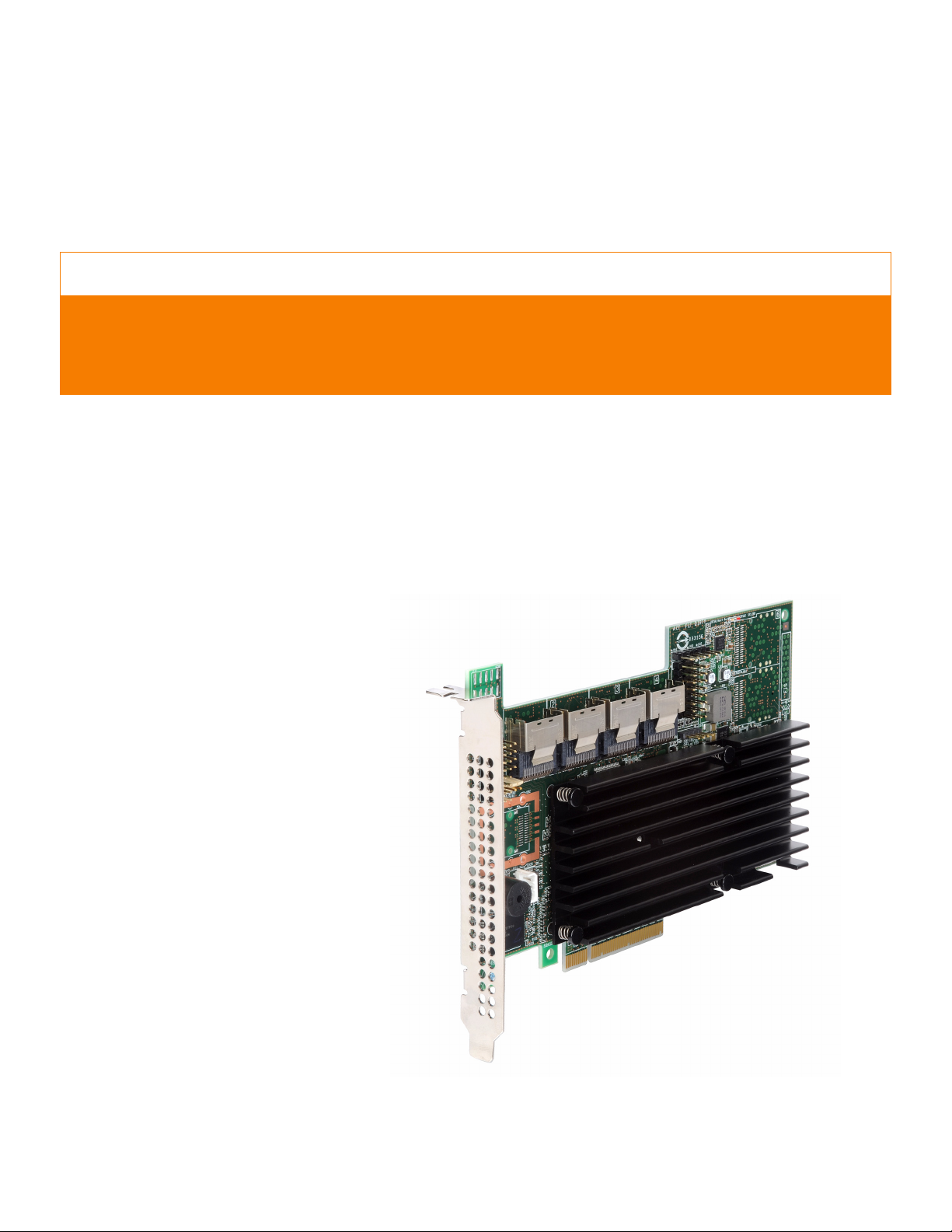
The MegaRAID® SAS 9260-16i RAID controller is a PCI-Express, standard-height,
half-length RAID controller that offers a 6 Gb/s transfer rate. The controller contains 16
internal SAS/SATA ports through four SFF-8087 x4 internal connectors.
Thank you for purchasing the LSI™ MegaRAID 6Gb/s SAS 9260-16i RAID controller. Your
MegaRAID controller provides reliability, high performance, and fault-tolerant drive
subsystem management. Before you install your RAID controller, please take a few
minutes to read this quick installation guide. If you need more information about any
topic covered in this guide, refer to the related documents on your MegaRAID Universal
Software Suite CD.
Figure1 shows the MegaRAID SAS 9260-16i RAID controller.
Figure 1: MegaRAID SAS 9260-16i RAID Controller
LSI Corporation Confidential | June 2010 Page 3
Page 4
Controller Installation
!
CAUTION
!
CAUTION
MegaRAID SAS 9260-16i RAID Controller Quick Installation GuideController Installation
NOTE: Record your controller serial number in a safe location in case you need to
contact LSI.
NOTE: SATA II is the only type of SATA supported by this RAID controller.
You can connect your MegaRAID SAS 9260-16i RAID controller remotely to the LSI
intelligent Battery Backup Unit 07 (LSIiBBU07) and the LSI intelligent Battery Backup
Unit 08 (LSIiBBU08). For more information about these batteries, refer to the MegaRAID
iBBU07 Intelligent Battery Backup Unit Quick Installation Guide and the MegaRAID iBBU08
Intelligent Battery Backup Unit Quick Installation Guide on the MegaRAID Universal
Software Suite CD.
Back up your data before changing your system configuration.
Otherwise, you might lose data.
1. Unpack the RAID Controller
Unpack the RAID controller in a static-free environment. Remove it from the
antistatic bag, and inspect it for damage. If the RAID controller appears to be
damaged, or if the MegaRAID Universal Software Suite CD is missing, contact LSI or
your MegaRAID OEM support representative.
The CD contains utility programs, device drivers for various operating systems, and
the following documentation:
— MegaRAID 6Gb/s SAS RAID Controllers User’s Guide
— MegaRAID SAS Software User’s Guide
— MegaRAID SAS Device Driver Installation User’s Guide
— Battery Backup Units for MegaRAID SAS RAID Controllers User’s Guide
— MegaRAID iBBU07 Intelligent Battery Backup Unit Quick Installation Guide
— MegaRAID iBBU08 Intelligent Battery Backup Unit Quick Installation Guide
— Software license agreement
2. Prepare the Computer
Turn off the computer, and unplug the power cords from the rear of the power
supply. Remove the cover from the computer.
Before you install the RAID controller, make sure that the computer is
disconnected from the power and from any networks.
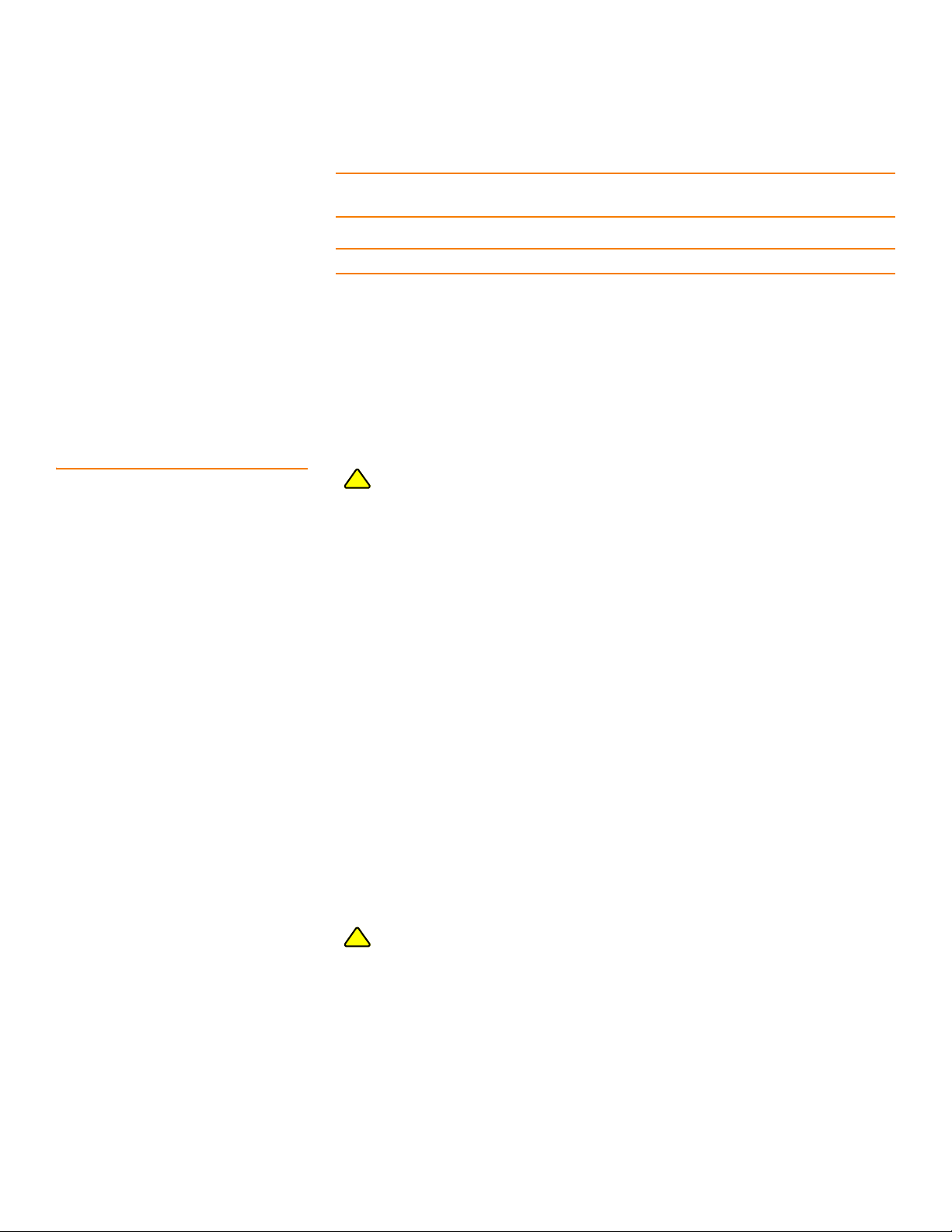
3. Review the Jumpers and the Connectors
Figure2 shows the location of the jumpers and the connectors on the RAID
controller. The jumpers are set at the factory, and you usually do not need to change
them.
Page 4 LSI Corporation Confidential | June 2010
Page 5
MegaRAID SAS 9260-16i RAID Controller Quick Installation Guide Controller Installation
85068-00
J2B1
Ports
0-3
J2B2
Ports
4-7
J3B1
Ports
8-11
J4B2
Ports
12-15
J1A2
J1B1
J1B3
J1C1
J2D1
J1L1
on
back
J4A2
J5A2
J4A3
J5B3
J4A1
J4A4
Figure 2: Layout of the SAS 9260-16i RAID Controller
NOTE: Pin 1 on the headers and the connectors is highlighted in black and red in
Figure2.
Tab le 1 describes the jumpers and the connectors on the RAID controller.
LSI Corporation Confidential | June 2010 Page 5
Page 6
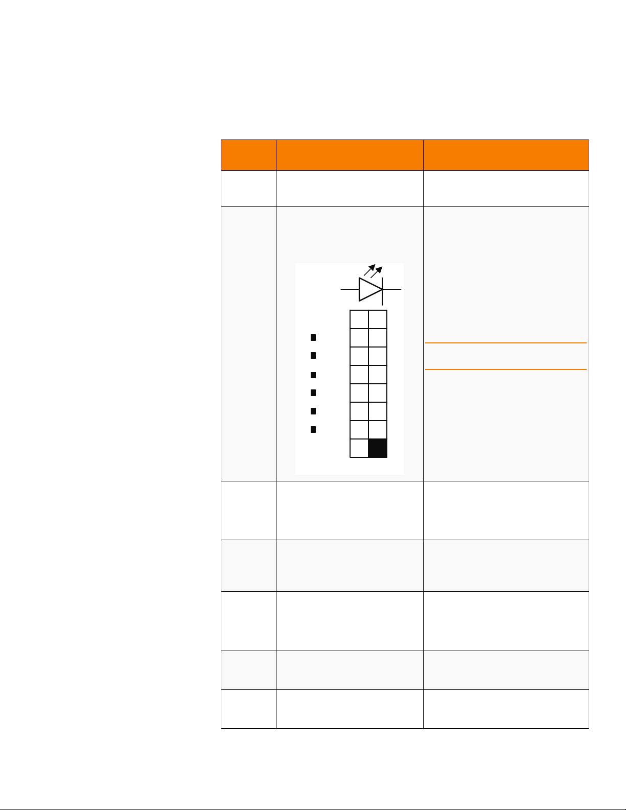
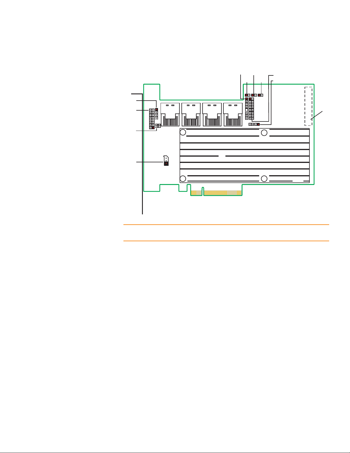
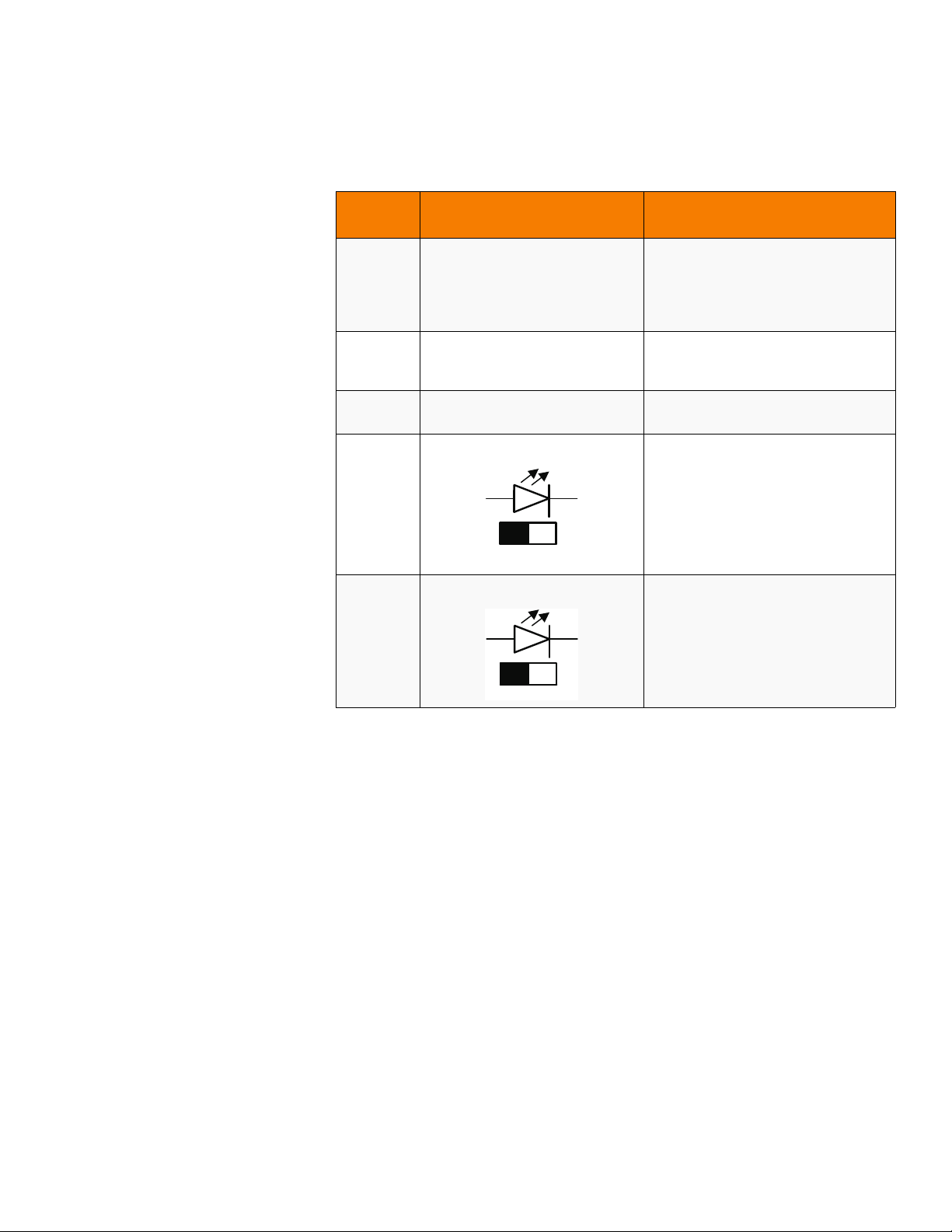
Table 1: Jumpers and Connectors
J1B1
PORT 0
PORT 7
+ve
-ve
ak
MegaRAID SAS 9260-16i RAID Controller Quick Installation GuideController Installation
Jumper/
Connector
J1A2 Universal Asynchronous
Receiver/Transmitter (UART) for the
Expander
J1B1 LED Locate and Fault Indication
header
Ports 0-3
Ports 4-7
Type Description
4-pin connector
Reserved for LSI use.
2x8-pin connector
Connects to an LED that indicates whether
a drive is in a fault condition. There is one
LED per port. When lit, each LED indicates
the corresponding drive has failed or is in
the unconfigured-bad state.
The LEDs function in a direct-attach
configuration (there are no SAS
expanders). Direct attach is defined as a
maximum of one drive connected directly
to each port.
NOTE: This header is used for RAID
controllers with internal SAS ports only.
J1B3 Advanced Software Hardware Key
J1C1
J1L1 Remote Battery Backup connector
header
IPMI-style I2C connector
(on the backside of the controller)
J2B1 x4 SAS Ports 0-3 internal connector SFF-8087 x4 internal mini SAS connector
J2B2 x4 SAS Ports 4-7 internal connector SFF-8087 x4 internal mini SAS connector
Page 6 LSI Corporation Confidential | June 2010
2-pin header
Enables support for selected advanced
features, which include recovery,
CacheCade, FastPath, and SafeStore disk
encryption.
3-pin connector
Supports SES (SCSI enclosure services)
2
C through an internal I2C backplane
over I
cable.
20-pin connector
Connects the LSIiBBU07 intelligent Battery
Backup Unit or the LSIiBBU08 intelligent
Battery Backup Unit remotely to the RAID
controller.
Connects the controller by cable to SAS
drives or SATA 2 drives.
Connects the controller by cable to SAS
drives or SATA 2 drives.
Page 7
MegaRAID SAS 9260-16i RAID Controller Quick Installation Guide Controller Installation
J4A2
+ve
ak
-ve
J4A3
ak
+ve
-ve
Table 1: Jumpers and Connectors (Continued)
Jumper/
Connector
J2D1 Standard edge card connector The RAID controller interfaces with the
J3B1 x4 SAS Ports 8-11 internal connector SFF-8087 x4 internal mini SAS connector
J4A1 Module CPLD 1x8-pin connector
J4A2 Activity LED header 2-pin connector
J4A3 Global drive fault LED header 2-pin connector
Type Description
host system though a standard edge card.
This interface provides power to the board
2
and an I
bus for IPMI.
Connects the controller by cable to SAS
drives or SATA 2 drives.
Reserved for LSI use.
Connects to an LED that indicates activity
on the drives connected to the controller.
Connects to an LED that indicates whether
a drive is in a fault condition.
C interface connected to the I2C
LSI Corporation Confidential | June 2010 Page 7
Page 8

MegaRAID SAS 9260-16i RAID Controller Quick Installation GuideController Installation
J4A4
PORT 8
PORT 15
+ve-ve
ka
J5A2
ak
+ve -ve
Table 1: Jumpers and Connectors (Continued)
Jumper/
Connector
J4A4 LED Locate and Fault Indication
header
Ports 8-11
Ports 12-15
Type Description
2x8-pin header
Connects to an LED that indicates whether
a drive is in a fault condition. There is one
LED per port. When lit, each LED indicates
the corresponding drive has failed or is in
the Unconfigured-Bad state.
The LEDs function in a direct-attach
configuration (there are no SAS
expanders). Direct attach is defined as a
maximum of one drive connected directly
to each port.
NOTE: This header is used for RAID
controllers with internal SAS ports only.
J4B2 x4 SAS Ports 12-15 internal
connector
J5A2 Write pending LED header 2-pin connector
J5B3 Universal Asynchronous
Receiver/Transmitter (UART)
debugging
SFF-8087 x4 internal mini SAS connector
Connects the controller by cable to SAS
drives or SATA 2 drives.
Connects to an LED that indicates when
the data in the cache has yet to be written
to the storage devices. Used when the
write-back feature is enabled.
4-pin connector
Reserved for LSI use.
4. Install the RAID Controller
Insert the controller into a PCI Express slot on the motherboard, as shown in
Figure3. Press down gently, but firmly, to seat the card correctly in the slot. Secure
the RAID controller to the computer chassis with the bracket screw.
Page 8 LSI Corporation Confidential | June 2010
Page 9

MegaRAID SAS 9260-16i RAID Controller Quick Installation Guide Controller Installation
85068-01
Screw
PCI Socket
Edge of
Motherboard
Press
Here
Press
Here
NOTE: This is a PCI Express x8 card and it can operate in x8 or x16 slots. However, some
PCIe slots support only PCIe graphics cards; if a RAID controller is installed, it will not
function.
NOTE: Refer to the guide for your motherboard for information about the PCI Express
slot.
Figure 3: Installing the MegaRAID SAS 9260-16i RAID Controller
5. Configure and Install the SAS Devices, SATA II Devices, or Both in the Host
Computer Case
Refer to the documentation for the devices for any preinstallation configuration
requirements.
6. Connect the RAID Controller to the SAS Devices, SATA II Devices, or Both in the
Host Computer Case
Use SAS cables to connect the RAID controller to SAS devices, SATA II devices, or
both. See Figure2 to view the connector locations.
NOTE: Refer to the MegaRAID 6Gb/s SAS RAID Controllers User’s Guide on the MegaRAID
Universal Software Suite CD for detailed information about the SAS cables.
7. Turn on the Power to the Computer
LSI Corporation Confidential | June 2010 Page 9
Page 10

MegaRAID SAS 9260-16i RAID Controller Quick Installation GuideSupported RAID Levels
Reinstall the computer cover, and reconnect the power cords. Turn on the power to
the computer. Make sure that the power is turned on to the SAS devices and the
SATA II devices before or at the same time that the power to the host computer is
turned on. If the power is turned on to the computer before it is turned on to the
devices, the computer might not recognize the devices.
The firmware takes several seconds to initialize. During this time, the controller
scans the ports.
8. Run the WebBIOS Configuration Utility
Run the WebBIOS Configuration Utility to configure the groups and the virtual
drives. When the message Press <Ctrl><H> for WebBIOS appears on the
screen, immediately press CTRL+H to run the utility.
NOTE: Refer to the MegaRAID SAS Software User’s Guide for detailed steps on
configuring groups and virtual drives.
9. Install the Operating System Driver
The controller can operate under various operating systems, but you must install
the software drivers first.
The MegaRAID Universal Software Suite CD includes the software drivers for the
supported operating systems, along with documentation. You can view the
supported operating systems and download the latest drivers for RAID controllers
from the LSI web site at:
http://www.lsi.com/cm/DownloadSearch.do. Access the download center, and
follow the steps to download the driver.
Refer to the MegaRAID SAS Device Driver Installation User’s Guide on the MegaRAID
Universal Software Suite CD for more information about installing the driver. Be sure
to use the latest service packs that are provided by the operating system
manufacturer and to review the readme file that accompanies the driver.
Supported RAID Levels This RAID controller supports drive groups using the following RAID levels:
RAID 0 (data striping): Data is striped across all drives in the group, enabling very
fast data throughput. There is no data redundancy. All data is lost if any drive fails.
RAID 1 (drive mirroring): Data is written simultaneously to both drives in the drive
group, providing complete data redundancy if one drive fails. RAID 1 supports an
even number of drives from 2 to 32 in a single span.
RAID 5 (drive striping with distributed parity): Data is striped across all drives in
the group. Part of the capacity of each drive stores parity information that
reconstructs data if a drive fails. RAID 5 provides good data throughput for
applications with high read request rates.
RAID 6 (drive striping with distributed parity across two drives): Data is striped
across all drives in the group and two parity drives are used to provide protection
against the failure of up to two drives. In each row of data blocks, two sets of parity
data are stored.
Page 10 LSI Corporation Confidential | June 2010
Page 11

MegaRAID SAS 9260-16i RAID Controller Quick Installation Guide Technical Support
RAID 00 (data striping across RAID 0 drive groups): RAID 00 is a spanned drive
group that creates a striped set from a series of RAID 0 drive groups.
RAID 10 (RAID 1 and RAID 0 in spanned groups): RAID 10 uses mirrored pairs of
drives to provide complete data redundancy. RAID 10 provides high data
throughput rates.
RAID 50 (RAID 5 and RAID 0 in spanned groups): RAID 50 uses both parity and
drive striping across multiple drives to provide complete data redundancy. RAID 50
provides high data throughput rates.
RAID 60 (RAID 6 and RAID 0 in spanned groups): RAID 60 uses both distributed
parity across two parity drives and drive striping across multiple drives to provide
complete data redundancy and high fault tolerance.
NOTE: Refer to the MegaRAID SAS Software User’s Guide on the MegaRAID Universal
Software Suite CD for more information about RAID levels
Technical Support For assistance in installing, configuring, or running the SAS 9260-16i RAID controller,
contact an LSI Technical Support representative.
Click the following link to access the LSI Technical Support page for storage and board
support:
http://www.lsi.com/support/storage/tech_support/index.html
From this page, you can send an email or call Technical Support, or submit a new
service request and view its status.
E-mail:
http://www.lsi.com/support/support_form.html
Phone Support:
http://www.lsi.com/support/storage/phone_tech_support/index.html
1-800-633-4545 (North America)
00-800-5745-6442 (International)
NOTE: The international toll-free number does not require country-specific access
codes.
LSI Corporation Confidential | June 2010 Page 11
Page 12

 Loading...