

Page 1
43013- 00B
!
CAUTION
!
CAUTION
MegaRAID SAS 9240-4i and SAS 9240-8i RAID Controllers
Quick Installation Guide
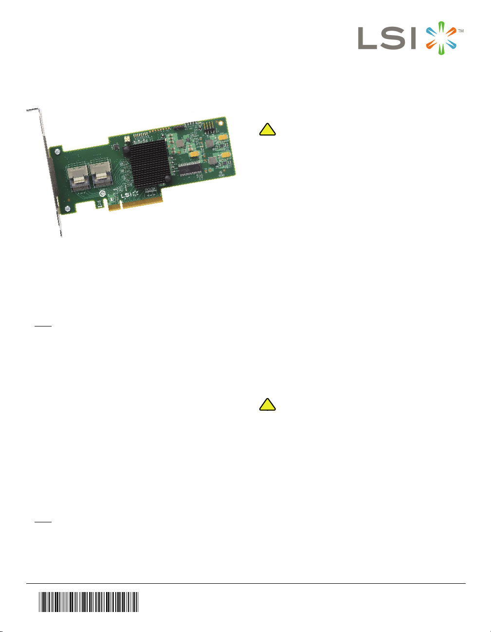
Thank you for purchasing the MegaRAID® SAS 9240-4i
RAID controller or the MegaRAID SAS 9240-8i RAID
controller. Before you install your RAID controller, please
take a few minutes to read this quick installation guide. If you
need more information about any topic covered in this guide,
refer to the related documents on your MegaRAID Universal
Software Suite CD.
Note
: Record your controller serial number in a safe
location in case you need to contact LSI.
The MegaRAID SAS 9240-4i RAID controller and the
MegaRAID SAS 9240-8i RAID controller are PCI-Express
2.0, half-size, full-height RAID controllers based on the
LSISAS2008 PCI Express-SAS/SATA I/O Processor chip.
The MegaRAID SAS 9240-4i RAID controller controls four
internal 6-Gb/s SAS/SATA ports through one SFF-8087 SAS
x4 internal connector.
The MegaRAID SAS 9240-8i RAID controller controls eight
internal 6-Gb/s SAS/SATA ports through two SFF-8087 SAS
x4 internal connectors.
There are two differences between the SAS 9240-4i RAID
controller and the SAS 9240-8i RAID controller:
– The SAS 9240-4i supports four ports and the SAS
9240-8i supports eight ports.
– The SAS 9240-4i does not have the connector for
ports four through seven.
Note
: SATA II is the only type of SATA supported by
these RAID controllers.
RAID CONTROLLER INSTALLATION
Back up your data before you change your
system configuration. Otherwise, you might lose
data.
Step 1 Unpack the RAID Controller
Unpack the RAID controller in a static-free
environment. Remove it from the antistatic bag,
and inspect it for damage. If the RAID controller
appears to be damaged, or if the MegaRAID
Universal Software Suite CD is missing, contact
LSI or your MegaRAID OEM support
representative.
The CD contains utility programs, device drivers
for various operating systems, and the following
documentation:
• MegaRAID 6Gb/s SAS RAID Controllers
User’s Guide
• MegaRAID SAS Software User’s Guide
• MegaRAID SAS Device Driver Installation
User’s Guide
• Software license agreement
Step 2 Prepare the Computer
Turn off the computer, and unplug the power
cords from the rear of the power supply. Remove
the cover from the computer.
Before you install the RAID controller, make sure
that the computer is disconnected from the power
and from any networks.
Step 3 Review the Jumpers and the Connectors
Figure 1 shows the location of the jumpers and
the connectors on the SAS 9240-4i RAID
controller. The jumpers are set at the factory, and
you usually do not need to change them.
Page 2
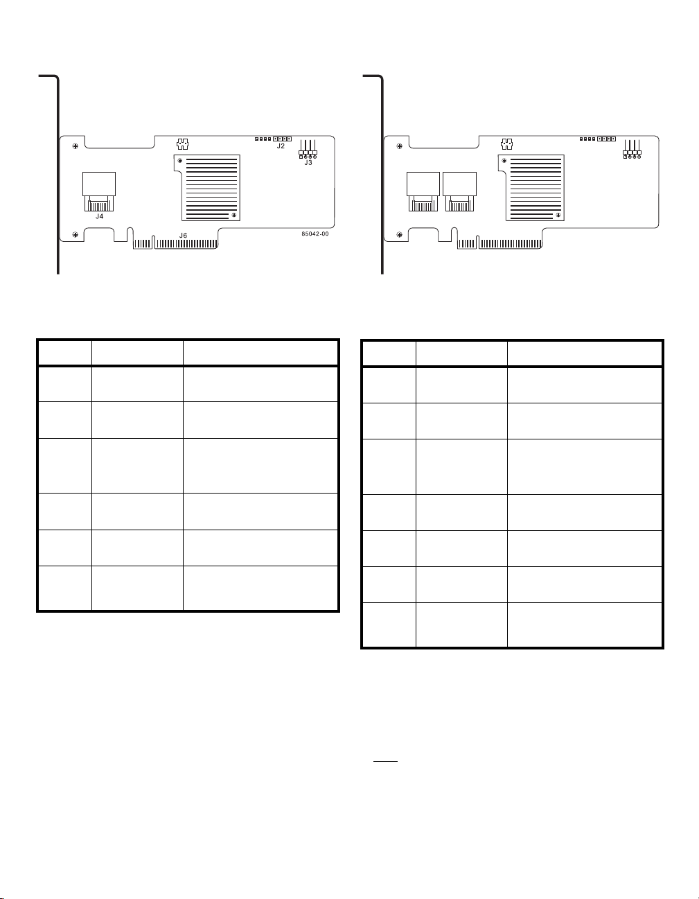
Figure 1 Layout of the MegaRAID SAS 9240-4i
J4
J2
J6
85043-00
J5
J3
RAID Controller
Figure 2 Layout of the MegaRAID SAS 9240-8i
RAID Controller
Ta bl e 1 describes the jumpers and the connectors
on the SAS 9240-4i RAID controller.
Table 1 SAS 9240-4i Jumpers and Connectors
Jumper/
Connector Type Description
J1 RISCwatch header 16-pin header
Reserved for LSI use.
J2 CPLD header 10-pin header
Reserved for LSI use.
J3 External LED drive
J4 x4 Mini-SAS (SFF-
J6 PCI Express x8
TP1 Universal Asyn-
activity/fault header
8087) Ports 0–3
internal connector
board edge
connector
chronous Receiver/
Transmitter (UART)
debugging
4-pin connector
Connects to external, green or red
LEDs that indicate drive activity or
faults.
Connects the cables from the
controller to SAS drives or SATA II
drives, or a SAS expander.
x8 interface that provides
connections on both the top and
the bottom of the board.
4-pin connector
Reserved for LSI use.
Figure 2 shows the location of the jumpers and the
connectors on the SAS 9240-8i RAID controller.
Ta bl e 2 describes the jumpers and the connectors
on the SAS 9240-8i RAID controller.
Table 2 SAS 9240-8i Jumpers and Connectors
Jumper/
Connector Type Description
J1 RISCwatch header 16-pin header
Reserved for LSI use.
J2 CPLD header 10-pin header
Reserved for LSI use.
J3 External LED drive
J4 x4 Mini-SAS (SFF-
J5 x4 Mini-SAS (SFF-
J6 PCI Express x8
TP1 Universal Asyn-
activity/fault header
8087) Ports 0–3
internal connector
8087) Ports 4–7
internal connector
board edge
connector
chronous Receiver/
Transmitter (UART)
debugging
4-pin connector
Connects to external, green or red
LEDs that indicate drive activity or
faults.
Connects the cables from the
controller to SAS drives or SATA II
drives, or a SAS expander.
Connects the cables from the
controller to SAS drives or SATA II
drives, or a SAS expander.
x8 interface that provides
connections on both the top and
the bottom of the board.
4-pin connector
Reserved for LSI use.
Step 4 Install the RAID Controller
Insert the RAID controller in a PCI Express slot
on the motherboard, as shown in Figure 3. Press
down gently, but firmly, to seat the card correctly
in the slot. Secure the RAID controller to the
computer chassis with the bracket screw.
Note
: Some PCI Express slots support only PCI
Express graphics cards; if a RAID controller is
installed, it will not function.
2 of 4
Page 3

Note
: These controllers also work in PCI Express first
generation slots. The PCI Express software is
backward compatible with previous revisions of
the PCI bus and the PCI-X bus. Refer to the
guide for your motherboard for information about
the PCI Express slot.
Figure 3 Installing the MegaRAID SAS 9240-4i or
SAS 9240-8i RAID Controller
Step 5 Configure and Install the SAS Devices, SATA
Step 6 Connect the RAID Controller to the SAS
Note
Step 7 Turn on the Power to the Computer
II Devices, or Both in the Host Computer Case
Refer to the documentation for the devices for any
preinstallation configuration requirements.
Devices, SATA II Devices, or Both in the Host
Computer Case
Use SAS cables to connect the RAID controller to
SAS devices, SATA II devices, or both. See
Figure 1 or Figure 2 to view the connector
locations, depending on which controller you
have.
: Refer to the MegaRAID 6Gb/s SAS RAID
Controllers User’s Guide on the MegaRAID
Universal Software Suite CD for detailed
information about the SAS cables.
Reinstall the computer cover and reconnect the
power cords.
Turn on power to the computer, making sure that
the power is turned on to the SAS devices and
the SATA II devices before or at the same time
that the power to the host computer is turned on.
If the power is turned on to the computer before
it is turned on to the devices, the computer might
not recognize the devices.
The firmware takes several seconds to initialize.
During this time, the controller scans the ports.
Step 8 Run the WebBIOS Configuration Utility
Run the WebBIOS Configuration Utility to
configure the groups and the virtual drives. When
the message Press <Ctrl><H> for WebBIOS
appears on the screen, immediately press
CTRL+H to run the utility.
Note
: Refer to the MegaRAID SAS Software User’s
Guide on the MegaRAID Universal Software
Suite CD for detailed steps on configuring groups
and virtual drives.
Step 9 Install the Operating System Driver
The controller can operate under various
operating systems, but you must install the
software drivers first.
The MegaRAID Universal Software Suite CD
includes the software drivers for the supported
operating systems, along with documentation.
You can view the supported operating systems
and download the latest drivers for RAID
controllers from the LSI web site at:
http://www.lsi.com/cm/DownloadSearch.do.
Access the download center, and follow the steps
to download the driver.
Refer to the MegaRAID SAS Device Driver
Installation User’s Guide on the MegaRAID
Universal Software Suite CD for more information
about installing the driver. Be sure to use the
latest service packs that are provided by the
operating system manufacturer and to review the
readme file that accompanies the driver.
SUPPORTED RAID LEVELS
The SAS 9240-4i RAID controller and the SAS 9240-8i RAID
controller support drive groups using the following RAID
levels:
• RAID 0 (data striping): Data is striped across all drives
in the group, enabling very fast data throughput. There is
no data redundancy. All data is lost if any drive fails.
• RAID 1 (drive mirroring): Data is written simultaneously
to both drives in the drive group, providing complete data
redundancy if one drive fails. RAID 1 supports an even
number of drives from 2 to 32 in a single span.
• RAID 5 (drive striping with distributed parity): Data is
striped across all drives in the group. Part of the capacity
3 of 4
Page 4

of each drive stores parity information that reconstructs
data if a drive fails. RAID 5 provides good data throughput
for applications with high read request rates.
• RAID 10 (RAID 1 and RAID 0 in spanned groups):
RAID 10 uses mirrored pairs of drives to provide complete
data redundancy. RAID 10 provides high data throughput
rates.
Note
: Refer to the MegaRAID SAS Software User’s
Guide on the MegaRAID Universal Software
Suite CD for more information about RAID levels.
TECHNICAL SUPPORT
For assistance in installing, configuring, or running the SAS
9240-4i RAID controller or the SAS 9240-8i RAID controller,
contact an LSI Technical Support representative.
Click the following link to access the LSI Technical Support
page for storage and board support:
http://www.lsi.com/support/storage/tech_support/index.html
From this page, you can send an email or call Technical
Support, or submit a new service request and view its status.
E-mail:
http://www.lsi.com/support/support_form.html
Phone Support:
http://www.lsi.com/support/storage/phone_tech_support/
index.html
1-800-633-4545 (North America)
00-800-5745-6442 (International
: The international toll-free number does not
Note
require country-specific access codes.
43013-00 Rev. B, June 2010
Find a list of LSI Corporation’s U.S. distributors, international distributors, sales
offices, and design resource centers on the LSI web site at:
http://www.lsi.com
LSI, the LSI logo design, and MyStorage are trademarks or registered trademarks
of LSI Corporation. All other brand and product names may be trademarks of their
respective companies.
Copyright © 2009-2010 by LSI Corporation. All rights reserved.
LSI Corporation reserves the right to make changes to any products and services
herein at any time without notice. LSI does not assume any responsibility or liability
arising out of the application or use of any product or service described herein,
except as expressly agreed to in writing by LSI; nor does the purchase, lease, or
use of a product or service from LSI convey a license under any patent rights,
copyrights, trademark rights, or any other of the intellectual property rights of LSI
or of third parties.
 Loading...