

Page 1
Quick Installation Guide
LSI® SAS 9211-4i PCI Express® to 6Gb/s SAS Host Bus Adapter
To install the LSI® SAS 9211-4i HBA, follow these steps:
1. Unpack the HBA, and inspect it for damage. Unpack the HBA in a static-free environment.
Remove the HBA from the antistatic bag, and carefully inspect the device for damage. If you notice
any damage, contact LSI or your reseller support representative.
ATTENTION: To avoid the risk of data loss, make a backup of your data before changing your
system configuration.
2. Prepare the computer. Turn off the computer, and remove the power cord from the rear of
the power supply.
CAUTION: Disconnect the computer from the power supply and from any networks to which
Thank you for purchasing the
LSI SAS 9211-4i Host Bus Adapter
(HBA). Please take a few minutes to
read this quick installation guide
before you install the HBA.
For more information about any
topic covered in this guide, refer to
the documents listed with your
product at the following link:
http://go.lsi.com/hbas
After navigating to your product, select
Software Downloads to locate necessary
device drivers.
ATTENTION: Perform all installation work
at an electrostatic discharge
(ESD)-safe workstation that
meets the requirements of
EIA-625.
Handling Electrostatic Discharge
Sensitive Devices. You must
perform all actions in
accordance to the latest
revision of the IPC-A-610 ESDrecommended practices.
Requirements for
3. Remove the cover from the chassis.
4. Check the mounting bracket on the HBA (system dependent). If required for your system,
replace the full-height mounting bracket that ships on the HBA with the low-profile bracket
supplied. Complete step a through step d to attach the short bracket.
CAUTION: Damaging the screw can void the warranty. To prevent damage to the screw,
CAUTION: Exceeding these torque specifications can damage the board, connectors, or
5. Insert the HBA in an available PCIe® slot. Locate an empty PCIe slot. Remove the blank
bracket panel on the back of the computer that aligns with the empty PCIe slot. Save this bracket
screw, if applicable. Align the HBA to a PCIe slot. Press down gently, but firmly, to seat the HBA
correctly in the slot. The following figure shows how to insert the HBA in a PCIe slot.
you will install the HBA, or you risk damaging the system or experiencing
electrical shock.
a. Using a #1 Phillips screwdriver that is ESD safe, remove the two Phillips screws that
connect the full-profile bracket to the board. Unscrew the two screws located at the top and
bottom edges of the board. Avoid touching any other board components with the
screwdriver or bracket.
center the screwdriver in the top of the screw.
b. Remove the full-profile bracket from the HBA. Do not damage the board.
c. Place the HBA on top of the low-profile bracket. Position the bracket so that the screw
holes in the tabs align with the openings in the board.
d. Using a #1 Phillips torque screwdriver that is ESD safe, set to a maximum torque of
4.8 ± 0.5 inch-pounds. Replace the two Phillips screws removed in step a.
screws, and can void the warranty on the HBA.
42614-01A
Page 2
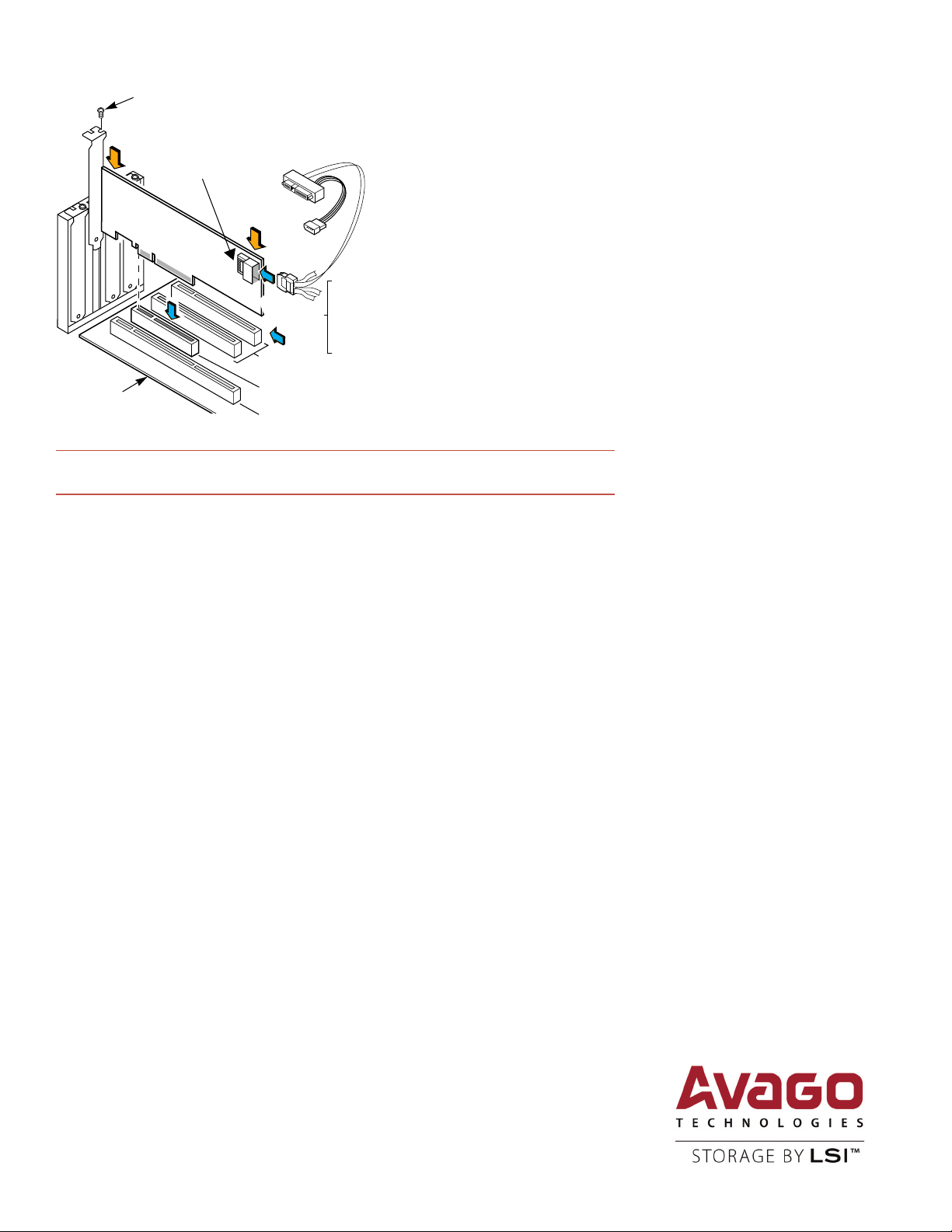
Bracket
Screw
Press
Here
Mini-SAS x4 (SFF-8087)
Internal Connector with Shell
Press
Here
Mini-SAS x4
(SFF-8087)
to SAS x1
Internal
Fan-Out
Cable
Edge of
Host Board
32-bit Slots
(3.3 V Only)
PCI Express
X8 Slot
64-bit Slot
(3.3 V Only)
NOTE: The shape, size, and locations of the components on your HBA and its bracket might vary
from this illustration. The HBA requires a x8 PCIe slot.
6. Secure the HBA bracket to the system’s chassis. Install the bracket screw, if applicable, or
engage the system retention mechanism to secure the HBA to the system’s chassis.
7. Connect internal SAS cables between the HBA and the SAS backplane or any other
SATA or SAS device. The LSISAS9211-4i has one internal x4 mini-SAS connector that connects to
four 6Gb/s SAS ports. Use the appropriate cable to connect the HBA to SAS or SATA storage
devices.
For connection to internal drives or backplanes, use an internal cable with a standard mini-SAS
connector (SFF-8087) on the controller side of the cable. The other end of the cable may fan out
into four SAS-style cables for direct connection to SAS or SATA disk drives. The previous figure
illustrates the connector locations on the LSISAS9211-4i and the use of a controller-based, fan-out
cable to connect to drives that require a SAS-style signal connector.
8. Replace the cover of the chassis.
9. Reconnect any power cords, and power up the system. Reconnect any power cords and
reconnect any network cables. Turn on the power.
TECHNICAL SUPPORT
For assistance installing, configuring, or
running the LSI SAS 9211-4i HBA, contact LSI
Technical Support:
E-mail: globalsupport.pld@avagotech.com
Web Site: www.lsi.com/support/
WARRANTY NOTICE
1. The warranty does not cover the return
of parts damaged by changing the bracket.
2. The warranty does not cover ESD
damage to the HBA. HBAs returned without a
bracket mounted on the board will be
returned without return merchandise
authorization (RMA) processing.
The hardware installation of your LSI 6Gb/s SAS HBA is complete.
DRIVER INSTALLATION
All driver installation instructions are available at http://go.lsi.com/hbas. Select 6Gb/s SAS HBAs >
Product Name > Software Downloads.
Avago Technologies, the A logo, LSI, and Storage by LSI are trademarks of Avago Technologies in the United States and/or other countries. All
other brand and product names may be trademarks of their respective companies.
Corporate Headquarters Email Website
San Jose, CA globalsupport.pdl@avagotech.com www.lsi.com
Document Number: 42614-01A
Copyright © 2014 Avago Technologies
All Rights Reserved. October 2014.
 Loading...