

Autopilot Pool Pilot Digital Nano Owners And Installation Manual
®
AutoPilot
Owners / Installation Manual
®
Pool Pilot
Digital Nano / Nano+
Digital Nano Models: 75041A, 75041A-xx
Manifolds: PPM1, PPM1M
Cell: PPC1
Digital Nano+ Models: 75043A, 75043A-xx
Manifolds: PPM2, PPM2M
Cells: PPC1 or PPC2
Including the Optional Pool Cover Detect Switch and the 1–28 Day Surface Cure Delay
Instructions.
Important!
This manual covers the installation and operation of the Digital Nano / Nano+ Chlorine Generators.
Read this manual and product labels before installing or operating this equipment.
INSTALLER: THIS DOCUMENT IS PURCHASER’S PROPERTY AND IS TO REMAIN WITH THE EQUIPMENT OWNER
LTP0086 REV 5


Table of Contents
Section 1 - General Information
1.1 Contacting AquaCal AutoPilot, Inc. 1
Section 2 - Safety Information
2.1 Safety Information 1
Section 3 - Owner Quick Start & Run
3.1 How Your Chlorinator Works 3
3.2 Owner / Operator Control Buttons, Check System LED and Audio Alarm 4
3.2.a UP and DOWN Arrows 4
3.2.b The BOOST Button 4
3.2.c MENU and SELECT Button 5
3.2.d CHECK SYSTEM Light and Audio Alarm 5
3.3 Normal Display Modes 5
3.3.a Purifier Mode 5
3.3.b Water Temperature 5
3.3.c CHECK SYSTEM Light 5
3.4 Water Balance and Chemistry Recommendations 5
Section 4 - Specifications and Approvals
4.1 Specifications 6
4.2 Manifold Pressure Drop vs Flow 7
4.3 Agency Approvals 7
Section 5 - Features
5.1 Patented Temperature Compensation 8
5.2 Water Manifold Assemblies - Available Options 8
5.2.a Automatic - Flow Bypass Manifold Assembly 9
5.2.b CoPilot Manifold Assembly 9
5.3 Additional Features with the 863A Expansion Board Option 10
5.3.a Automatically Reduce Chlorine Output When Pool Cover Closes 10
5.3.b 12/24 Hour Clock Display 10
5.3.c Set Purifier Off 11
Section 6 - Maintenance
6.1 Fuse Location and Ratings 11
6.2 Removing / Inspecting / Cleaning Tri-sensor 12
6.2.a Tri-sensor Assembly Overview 12
6.2.b Inspect Tri-sensor 12
6.2.c Cleaning Tri-sensor / Salt Sensor 13
6.2.d Test Tri-sensor Flow Switch 13
6.3 Servicing the Cell 14
6.3.a Removal 14
6.3.b Visual Inspection 14
6.3.c Manual Cleaning 15
6.3.d Installing 15
6.4 Winterizing 16
6.4.a Control Unit and Manifold Assembly 16
6.5 Spring Start Up 16
i

Section 7 - Programming
7.1 Control Panel 17
7.1.a Button Overview 17
7.1.b MENU / SELECT Button 17
7.1.c Display Overview 17
7.2 Menus 18
7.3 Basic Operational Programming 19
7.3.a Adjusting the Purifier Output % 19
7.3.b Boost or Super Boost 19
7.3.c Purifier Mode 19
7.3.d Purifier % Adjustment Procedure 20
7.4 Test Pool Pilot (Diagnostic Menu) 20
7.5 View Setup 21
7.6 Review Of Installer, Owner, & Maintenance Menu Programming 21
7.6.a Set Pool Volume 21
7.6.b Calibrate Salt 21
7.6.c Select Language 22
7.6.d Calibrate Temperature 22
7.6.e Select Units 22
7.6.f Set Temperature Unit 22
7.6.g Display Temperature 23
7.6.h Set Reverse Time 23
7.6.i Force Reverse 23
7.6.j Enable / Disable Audio Alarm 23
7.7 Menu Programming-Optional 863A Expansion Board Features 24
7.7.a Display time 24
7.7.b Set 12/24 Hour Clock 24
7.7.c Set Time of Day 24
7.7.d Select System 24
7.7.e Set Purifier Off 25
Section 8 - Installation
8.1 Basic System Overview 26
8.2 Planning the Installation 27
8.3 Check Parts 27
8.4 Installation Steps 27
8.5 Plumbing The System 28
8.5.a Plumbing the Manifold Assembly 28
8.6 Mounting the Chlorinator 29
8.7 Electrical Connections 29
8.7.a Electrical Connections Overview 29
8.7.b AC Input Voltage 30
8.7.c Low Voltage Wiring 31
8.7.d Installing the Optional 863A Expansion Board 31
8.7.e Connecting the Retractable Cover Switch (Option only available with
purchase of #863A Expansion Board) 33
8.7.f Bonding 33
ii

8.8 Preparing the Pool Water 34
8.8.a Calculating Pool Volume 34
8.8.b Steps to Prepare Water 34
8.8.c Adding Salt 35
8.9 Programming at Installation 36
Section 9 - Troubleshooting
9.1 Troubleshooting 36
9.2 Additional Troubleshooting for Units Equipped with Optional 863A Expansion
Board 43
Section 10 - Reference
10.1 Basic Water Chemistry 43
10.1.a Chlorine 45
10.1.b pH 45
10.1.c Total Alkalinity 45
10.1.d Calcium Hardness 45
10.1.e Cyanuric Acid 45
10.2 Using the Saturation Index 46
10.3 Salt Addition Chart 47
Section 11 - FCC Compliance
11.1 FCC Compliance 48
iii

SECTION 1 - GENERAL INFORMATION
1.1 Contacting AquaCal AutoPilot, Inc.
If you need to call AquaCal AutoPilot, Inc. for questions, services, or parts, please have your
model and serial numbers available. Also have the name of your installer and date of your
equipment’s installation. Please refer to our website for the latest manual revisions, additional
information, and helpful service advice.
Website www.autopilot.com
Phone (727) 823-5642
Fax (727) 821-7471
AquaCal AutoPilot, Inc.
Address
2737 24th Street North
St. Petersburg, FL 33713, USA
Pool volume
(Gallons / Liters)
Installer:
Installation Date:
Cell Type:
Cell Serial #:
Model Type:
Model Serial #:
SECTION 2 - SAFETY INFORMATION
2.1 Safety Information
l For personal safety, and to avoid damage to equipment, follow all safety instructions displayed on the
equipment and within this manual. Repair and service of your AutoPilot®chlorinator must be performed by
qualified service personnel.
l Should you suspect your chlorine generator is not performing properly, refer to the Troubleshooting
section in this manual to determine if service is required. See " Troubleshooting" on page 36.
l Warranties will be voided if the chlorinator has been improperly installed. Failure to properly operate,
maintain or repair the AutoPilot®chlorinator will void the factory warranty.
SAFETY SIGNALS
Throughout this manual safety signals are placed where particular attention is
required.
WARNING - Failure to heed the following may result in permanent injury or
death.
CAUTION - Failure to heed the following may result in equipment damage.
Follow all state provincial and NEC (National Electrical Codes) and applicable CEC (Canadian
Electrical Codes) unless local guidelines supersede. When installing and using your Pool Pilot®,
basic safety precautions must always be followed, including the following:
WARNING - Failure to heed the following may result in permanent injury or death.
l RISK OF ELECTRICAL SHOCK - Disconnect all AC power when installing or servicing this system.
Follow all state, local, and National Electrical Code(s) (provincial and Canadian Electrical Code(s) if
applicable). Use copper conductors only.
l RISK OF ELECTRICAL SHOCK - The Pool Pilot
components. Repairs must not be attempted by untrained and / or unqualified individuals. If service is
deemed necessary, contact installing dealer or AquaCal AutoPilot Customer Support.
®
chlorinator contains no owner-repairable
Page - 1

l RISK OF ELECTRICAL SHOCK - A bonding lug has been provided on the outside of the power supply.
This lug permits the connection of a No. 8 AWG (8.4 mm2) solid copper-bonding conductor (No. 6 AWG
in Canada). Make this connection between the Pool Pilot®power supply and all other electrical
equipment and exposed metal within 5-feet (1.5 m) of the unit. All field-installed metal components
(such as rails, ladders, drains, etc.) within 10-feet of the pool, spa, or hot tub, must be bonded to the
equipment grounding bus using copper conductors not smaller than No. 8 AWG (8.4 mm2) (No. 6 AWG
in Canada).
l RISK OF ELECTRICAL SHOCK - The Pool Pilot
®
chlorinators configured to 115 Vac must be installed
at least 10 feet (3 m) from the pool or spa wall. Pool Pilot®chlorinators configured to 230 Vac must be
installed at least 5 feet (1.5m) from the pool or spa wall.
l RISK OF ELECTRICAL SHOCK - A disconnect device incorporated into the fixed wiring must be
included in the supply circuit (such as a time clock, relay, or circuit breaker).
l RISK OF ELECTRICAL SHOCK - Connect only to a branch circuit protected by a ground-fault circuit-
interrupter (GFCI). Contact a qualified electrician if you cannot verify that the circuit is protected by a
GFCI.
l RISK OF ELECTRICAL SHOCK - The Pool Pilot
®
must be connected only to a supply circuit that is
protected by a ground-fault circuit-interrupter (GFCI). The GFCI must be tested on a routine basis. To
test, push the GFCI test button. Power should be interrupted. Push the reset button. Power should be
restored. If the GFCI fails to operate in this manner, it is defective.
l RISK OF ELECTRICAL SHOCK - If the ground-fault circuit-interrupter (GFCI) interrupts power to the
equipment without the test button being pushed, a ground current is flowing with a possibility of an
electrical shock. Do not use equipment. Disconnect the equipment and have the problem corrected by a
qualified service representative before using.
l CHEMICAL HAZARD - To avoid damaging splashes, always add acid to water, never water to acid.
Wear safety glasses and use other appropriate personal protection equipment.
l CHEMICAL HAZARD - Always follow the instructions on the manufacturer's label whenever handling or
using chemicals.
l CHEMICAL HAZARD – Heavy pool (or spa) usage and higher temperatures may require a higher
chlorine output in order to maintain proper free available chlorine residuals.
l WATER CHEMISTRY SAFETY - Improper water chemistry can present a serious health hazard. The
proper residual chlorine level and water chemistry must be maintained. The addition of certain pool
maintenance chemicals can reduce the effectiveness of chlorine. Maintain Pool / Spa water per
standards detailed later in this manual.
l COMBUSTIBLE HAZARD – The AutoPilot
®
chlorinator is equipped with an electronic flow switch that
automatically turns the unit off in the event of a “low water flow” situation. Do not tamper in any way with
this safety feature.
l PERSONAL SAFETY HAZARD – To reduce the risk of injury, do not permit children to operate this
device.
l RISK OF CHILD DROWNING OR INJURY - Children must be closely supervised at all times around pool
or spa equipment.
CAUTION - Failure to heed the following may result in equipment damage.
l The Pool Pilot
warranty.
l To permit proper air circulation, the Pool Pilot
above ground level or any other cooling obstruction.
l Special measures are required in the event of freezing conditions. Your Pool Pilot
measures are not taken in advance of freezing conditions. Equipment damage due to freezing
conditions is NOT covered under the equipment warranty.
l Do not use a pool cleaner or vacuum head with wheels, as wheels can leave track marks on newly-
plastered pools. Do not allow Granular salt to pile up in one location, without brushing, as staining may
occur.
l Excessively high chlorine levels can cause corrosion damage to pool fixtures and equipment.
®
must be installed and operated as specified. Failure to do so will void the equipment
®
power supply must be mounted at least 1-foot (30 cm)
®
may be damaged if
Page - 2

l For maximum cell life, maintain water in a balanced condition. Water maintained in a scaling condition
will shorten cell life and may render the Pool Pilot®inoperative. Damage and / or service calls, caused by
improper water balance, will NOT be covered under the equipment warranty.
l Scraping or scratching the titanium blade’s edge or surface will damage the blade catalyst coating and
cause premature failure of the cell... warranty will be voided. Never use any sharp or metallic objects to
remove scale.
l Reduced polarity reversing cycle times will reduce cell life, and should only be used due to
uncontrollable scale formation on the cell. ALWAYS test and adjust water balance, before attempting
scale control via shortening reverse period.
l The Tri-sensor should not be pulled out at an angle, or the flow paddle or flow post may be damaged.
SAVE THESE INSTRUCTIONS
SECTION 3 - OWNER QUICK START & RUN
1.
Balance the water chemistry according to the water chemistry parameters and salt recommendations.
See "Water Balance and Chemistry Recommendations" on page 5. See "Preparing the Pool Water"
on page 34.
l The Pool Pilot
inaccurate until the circulation pump has been run for 24 hours to fully dissolve newly added salt.
2.
Use the UP and DOWN arrow buttons to set the purifier percentage to 50%. Press SELECT to save
setting.
3.
During the first two weeks, test the water chemistry parameters every 3-4 days. Adjust purifier
percentage as needed.
4.
Once ideal purifier percentage has been determined, follow normal maintenance procedures.
®
may be started immediately. The salt reading, however, may initially be
3.1 How Your Chlorinator Works
The Pool Pilot®is designed to handle the purification needs of residential swimming pools and
spas. The amount of chlorine required for proper sanitization will vary based on the pool size
and factors such as water temperature, bather load, exposure to direct sunlight, and special
water features.
The system requires a low concentration of dissolved salt (sodium chloride) in the water. The
salt concentration is normally maintained below the taste threshold. The Pool Pilot
®
automatically converts salt into chlorine, which your pool / spa requires to remain sanitized and
algae free. The chlorine reverts back to salt after treating the water. Since the salt is constantly
recycled, there is minimal loss during a swimming season. However, salt can be lost due to filter
back washing, rain water overflow, leaks, or bather splashing / carry out, but not through
evaporation.
The water circulation pump must be operating for your Pool Pilot®to produce chlorine, so run
time is one of several key factors to maintaining proper sanitizer levels. Most installations require
a minimum of eight (8) hours-per-day pump run time to properly filter and sanitize the water.
Page - 3

3.2 Owner / Operator Control Buttons, Check System LED and Audio Alarm
The following is a brief explanation of owner or operator control buttons.
PLEASE NOTE:
This section assumes the installer has already programmed the system for specific
site parameters, has established proper water balance, and has pretreated water to
1 - 3 ppm (mg/L) chlorine.
ATTENTION OWNER:
Should Celsius vs. Fahrenheit, choice of language, or other owner options require
modification, refer to the Programming section of this manual. See "Review Of
Installer, Owner, & Maintenance Menu Programming" on page 21.
3.2.a UP and DOWN Arrows
Use the UP and DOWN arrows to control the purifier output level.
After output level is adjusted, press the SELECT button to save the value chosen. With a
properly prepared pool, the recommended starting output level is 50%.
Upon initial start-up, check sanitizer every 3-4 days and make small output level adjustments as
necessary to maintain 1 - 3 ppm (mg/L) free chlorine levels. Keep in mind, your Pool Pilot®does
not directly measure or regulate the sanitizer levels in your pool. Rather, the owner / operator will
need to periodically test the water to determine the current chlorine level, and adjust the output
setting as needed.
After the chlorine output level is “tuned in,” the unit will automatically make fine output
adjustments as the water temperature fluctuates. This temperature compensation feature will
adjust output depending on water temperature. See "Patented Temperature Compensation" on
page 8.
PLEASE NOTE:
The optimum output setting will vary based upon pool size, location, exposure to
sunlight, number of users, vegetation around the pool, water balance practices,
and pump run time. Your installer should have already taken these factors into
consideration when performing installation programming. Therefore, your
adjustments, at this point, should be relatively minor.
3.2.b The BOOST Button
The BOOST button increases output to 100%. Use this feature when a heavier than normal
bather load is anticipated.
Press BOOST once...................................... = 24 Hour Boost
Press and hold BOOST for 8 seconds...... = 72 Hour Boost
Press BOOST a second time...................... = Deactivate Boost
Page - 4

3.2.c MENU and SELECT Button
The MENU button allows the operator access to the “Test Pool Pilot”, “View setup”, “Owner
options”, “Maintenance” and “Installer” menus. See "Review Of Installer, Owner, & Maintenance
Menu Programming" on page 21.
Press the UP and DOWN arrows to scroll through the menus.
The SELECT button allows the operator to choose program menu options. The owner / operator
should not normally need to access these features on a regular basis.
Consult the "Programming" section for additional information related to the MENU and SELECT
buttons. See "Control Panel" on page 17. For an overview of all the menus & sub-menus,
consult the "Menus" section. See "Menus" on page 18.
3.2.d CHECK SYSTEM Light and Audio Alarm
The CHECK SYSTEM light will flash to warn the unit may need attention. A warning message
will also be displayed. If enabled, an audio alarm* may also be heard when the system light is
flashing. Unless deemed a normal condition, per below, refer to the "Troubleshooting" section.
l Flashes red when pump is off / water flow is insufficient (It is normal for the light to flash if the circulation
pump is off)
l Flashes when salt is low (check salt and add as needed)
l Flashes when water temperature exceeds 125° F (51° C), or drops below 10° F (-12° C)
*Note: When enabled, an audio alarm will sound due to any of the above three (3) conditions. If
water flow ceases (or falls below minimum acceptable levels) the alarm will automatically
silence after 10 minutes. See "Enable / Disable Audio Alarm" on page 23.
3.3 Normal Display Modes
3.3.a Purifier Mode
Purifier (Chlorine Output %) level.....................Shown in 1% increments
l Range with cover open ................................ 0% to 100%
l Range with cover closed .............................. 0% to 20%
3.3.b Water Temperature
Displayed in Fahrenheit or Celsius.
The Temperature can be turned off. See "Display Temperature" on page 23.
3.3.c CHECK SYSTEM Light
Off when operating normally. Normally blinking red when circulation pump is off and supply
power to the Pool Pilot®remains on. The light will also blink red when an error has occurred.
See " Troubleshooting" on page 36.
3.4 Water Balance and Chemistry Recommendations
Water balance is the relationship between different chemical measurements in your pool water.
A pool that is balanced has proper levels of pH, Total Alkalinity and Calcium Hardness.
Balanced water can also be defined as water that is not corrosive or scaling. Water that is not
balanced can damage equipment and pool surfaces. See "Basic Water Chemistry" on page 43.
Proper water chemistry levels are essential to maintain safe and consistent swimming pool
operation. Sanitizers are used to destroy harmful or otherwise objectionable organisms.
Stabilizer is used to prevent unnecessary loss of chlorine to sunlight. Salt is used by the Pool
Pilot®to generate chlorine sanitizer.
Page - 5

Please note the following recommended water chemistry parameters are for residential pool /
spa applications only. Follow local regulatory guidelines for any commercial pool applications.
Table 1
POOL SPA
Parameter Units Min Ideal Max Min Ideal Max
Free Chlorine ppm mg/L 1.0 2.0 - 4.0 5 2.0 3.0 - 4.0 10
Combin ed Chlo rine ppm mg/L 0.0 0.0 0.2 0.0 0.0 0.5
pH ppm mg/L 7.2 7.2 -7.8 7.8 7.2 7.2 -7.8 7.8
Total Alkalinity ppm mg/L 60 80 - 100 180 60 80 - 100 180
Calcium Hardness ppm mg/L 150 200 - 400 1000 100 150 - 250 1000
Salt ppm mg/L 2000 2500 - 4500 ** 2000 2500 - 4500 **
Cyanuric Acid (stab ilizer) ppm mg/L 0 30 - 50 *** 0 30 - 50 ***
** Typically 6,000 ppm (mg/L) or less is recommended; unit can operate with levels as high as 35,000+
ppm (mg/L).
*** This is dictated by state or local codes but is typically 80 ppm (mg/L).
See "Basic Water Chemistry" and "Using the Saturation Index" sections later in this manual for further
information concerning pool / spa water chemistry maintenance requirements. Refer to the
"Troubleshooting" section for assistance with resolving low or high chlorine issues.
SECTION 4 - SPECIFICATIONS AND APPROVALS
4.1 Specifications
75041A, 75041A-XX
SPECIFICATION
Input Power: 110-120 Vac 2.0A 220-240 Vac 1.0A 110-120 Vac 2.0A 220-240 Vac 1.0A
Cell Maximum Chlorine Output:
PPC1 0.8 lb. / day (15.1 g/hr) (standard) 0.8 lb. / day (15.1 g/hr) (standard
PPC2 not applicable 1.06 lb. / day (20.0 g/hr) (standard)
Manifold Type PPM1 & PPM1M PPM2 & PPM2M
Standard Cell PPC1 PPC2
Manifold Flow rates:
PPMxx (standard) Minimum 20 gpm (76 L/min); Maximum 70 gpm (265 L/min)
CoPilot Ozone
(optional)
Maximum Manifold
Pressure
(when converted to
110V-120V in the field)
Minimum 25 gpm (95 L/min); Maximum 70 gpm (265 L/min)
75 psi (586 kPa)
75041A,
75041A-XX
75043A, 75043A-XX
(when converted to
110V-120V in the field)
75043A,
75043A-XX
Cover Switch
Compatible
Models
Page - 6
75041A & 75043A (Discontinued models 75040A & 75042A)
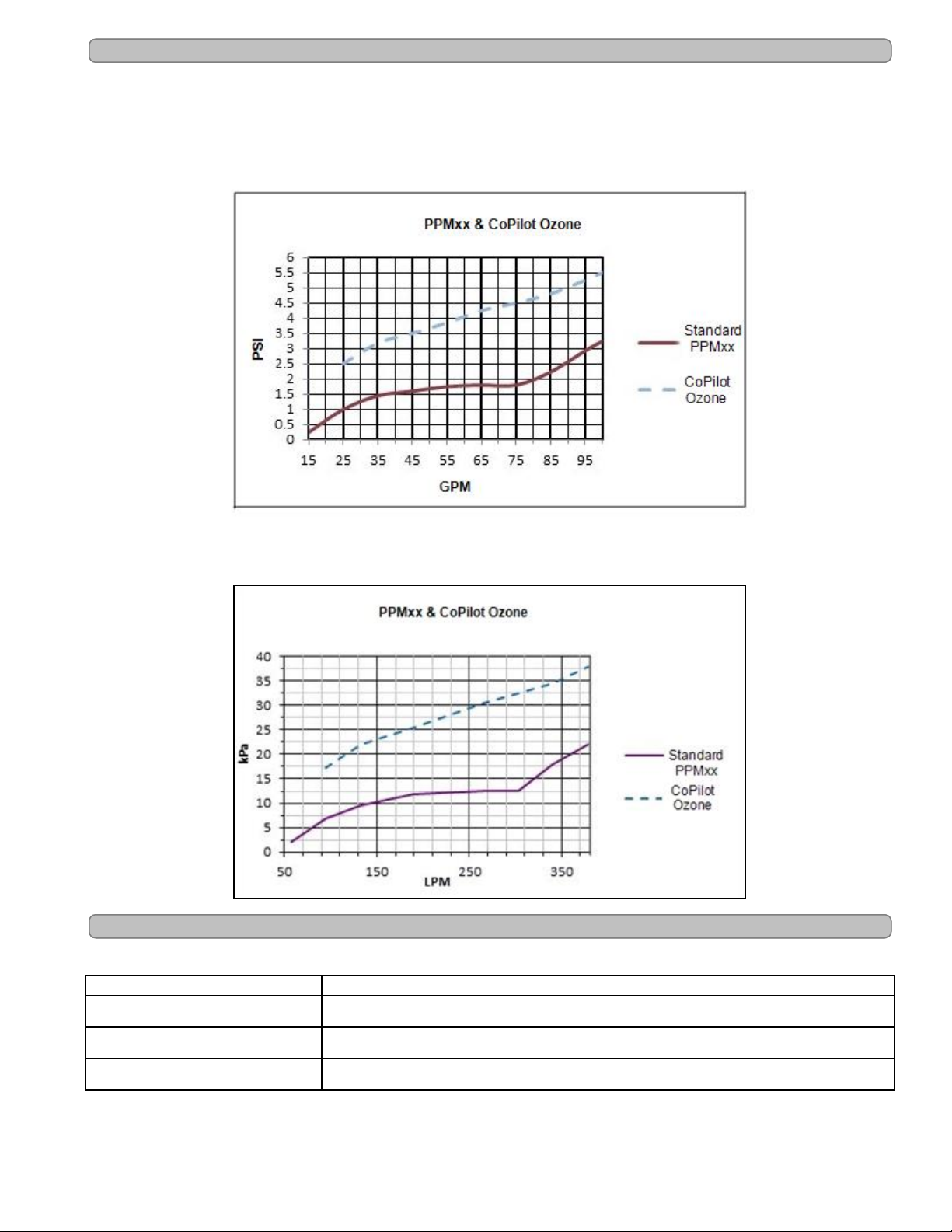
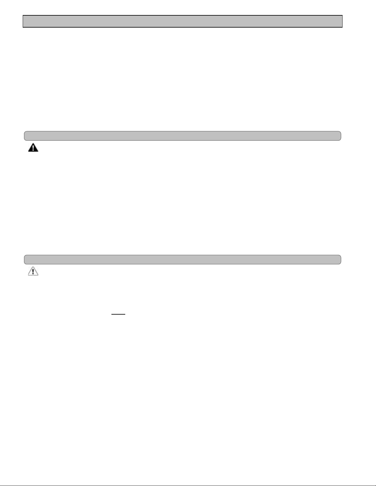
4.2 Manifold Pressure Drop vs Flow
The following chart shows pressure drop versus flow for all AutoPilot®manifolds.
The optional CoPilot®Ozone manifold is also listed.
Table 3
Table 4
4.3 Agency Approvals
Tested to conform to the following specifications:
SPECIFICATION DESCRIPTION
UL1081 Safety Standard for Swimming Pool Pumps, Filters and Chlorinators.
CAN / CSA-E60335-1 Safety of Household and Similar Electrical Appliances.
FCC See "FCC Compliance" on page 48.
Page - 7
SECTION 5 - FEATURES
l Patented temperature compensation for chlorine output control.
l Programmable microprocessor control.
l Multi-language digital display (English, Spanish, French, German, Italian and Czech).
l Digitally controlled power to the cell.
l Tri-sensor circuitry to monitor water flow, water temperature, and salt level.
l Calculates and displays amount of salt needed to reach the recommended 3,000 ppm (mg/L) salt
concentration level.
l On board diagnostic and test programs.
l Optional CoPilot
l Can automatically reduce purifier output when pool cover is closed. (Optional 863A Expansion Board and
Cover Switch must be installed.)
l Chlorine production (salt addition) can be delayed for up to 28 days.(Optional 863A Expansion Board)
5.1 Patented Temperature Compensation
WARNING - Failure to heed the following may result in permanent injury or death.
l Pool or Spa water temperature should not exceed 104°F (40°C).
The water temperature sensor works in conjunction with the purifier % feature to automatically
adjust chlorine output based upon changes in water temperature. This feature operates between
55°F and 125°F (13°C - 52°C).
As water temperature falls below 65°F (18°C), the controller will automatically reduce the purifier
% and will reduce the maximum % that can be selected. This feature prevents the controller from
generating excessive chlorine in cold water where it is not needed and prevents premature cell
failure.
®
upgrade brings Ozone to the pool.
At 55°F (13°C) or colder water temperatures, the controller will adjust to a fixed 1% output, thus
preventing over-chlorination and premature cell failure.
5.2 Water Manifold Assemblies - Available Options
CAUTION - Failure to heed the following may result in equipment damage.
l The Digital Nano manifold may only use the PPC1 cell. The Digital Nano+ may use either the PPC1 or
PPC2 cell.
The Digital Nano uses the automatic-flow bypass manifold assembly (models PPM1, PPM1M).
The Digital Nano should only use the PPC1 cell.
The Digital Nano+ uses the patented automatic-flow bypass manifold assembly (models PPM2,
PPM2M) with a PPC2 cell. The Digital Nano+ may also use a PPC1 cell, but the maximum
chlorine output will be lower. See "Specifications" on page 6.
The CoPilot®manifold assembly comes with an automatic-flow bypass, check valve assembly
and ozone injector venturi assembly.
Page - 8
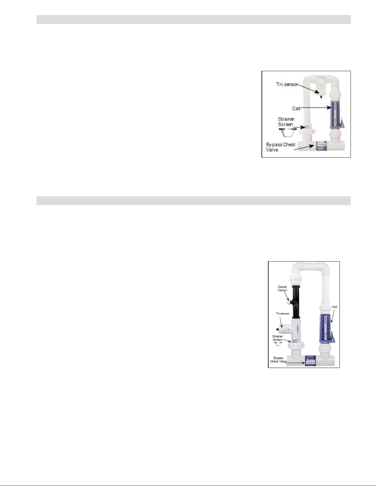
5.2.a Automatic - Flow Bypass Manifold Assembly
Models PPM1, PPM1M and PPM2, PPM2M:
The AutoPilot®manifold is connected into the plumbing after all other equipment. Water from the
pool / spa is moved though the manifold by the circulation pump. The manifold uses four key
components:
l
The Tri-sensor provides data (from electronic sensors) to the Pool Pilot
for monitoring water flow, water temperature, and salt concentration
level. The Pool Pilot®uses this data to determine if conditions are
suitable for the cell to operate; the signal read from the temperature
sensor allows the automatic temperature compensation feature to
function.
l
The Cell (PPCx) receives power from the Pool Pilot®and converts the
salt contained in the water to chlorine.
l
The Strainer Screen prevents debris in the water from entering the Trisensor or cell, and requires periodic inspection and cleaning.
l
The Bypass Check Valve allows the water flow rate to be slowed and
optimized through the cell, while permitting the pump to continue to
circulate water to-and-from the pool / spa at full flow rates. The reduced
water flow through the cell results in a more efficient "Super-Chlorination” effect, resulting in improved
overall sanitization.
®
Figure 1
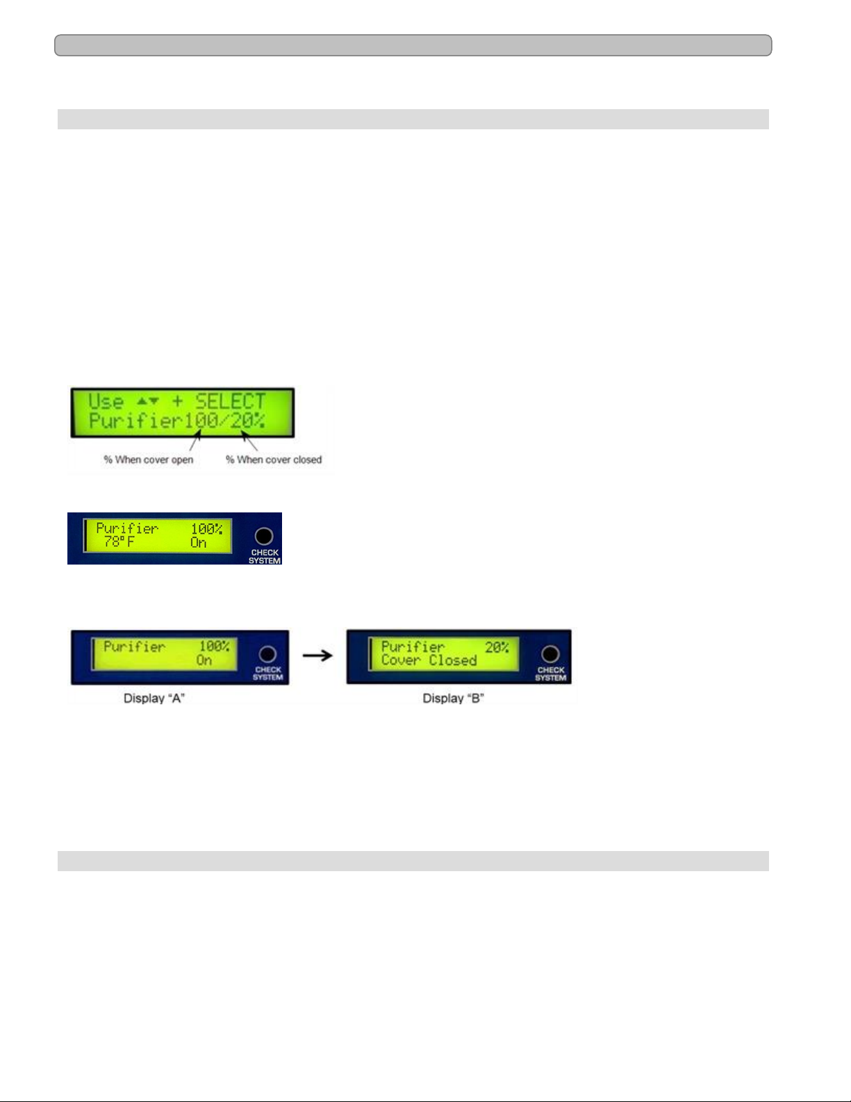
5.2.b CoPilot Manifold Assembly
The CoPilot®system is designed to be used in conjunction with the Pool Pilot®to reduce
chlorine demand and extend cell life. This system is also sold separately as an upgrade to
existing Pool Pilot®systems.
The manifold is connected into the plumbing after all other equipment. Water from the pool / spa
is moved though the manifold by the circulation pump:
l
The Tri-sensor provides data (from electronic sensors) to the Pool Pilot
for monitoring water flow, water temperature, and salt concentration level.
The Pool Pilot®uses this data to determine if conditions are safe for the cell
to operate; the signal read from the temperature sensor allows the
automatic temperature compensation feature to function.
l
The Cell (PPCx) receives power from the Pool Pilot®and converts the salt
contained in the water to chlorine.
l The Strainer Screen prevents debris in the water from entering the Tri-
sensor or cell, and requires periodic inspection and cleaning.
l
The Bypass Check Valve allows the water flow rate to be slowed and
optimized through the cell, while permitting the pump to continue to
circulate water to-and-from the pool / spa at full flow rates. The reduced
water flow through the cell results in a more efficient "Super-Chlorination”
effect, resulting in improved overall sanitization.
l
The Ozone Venturi Injector introduces ozone directly into the water
before the Pool Pilot®cell. The ozone venturi injector is connected to the CoPilot
via an Ozone Check Valve and Tube Assembly (not shown).
®
Figure 2
®
Page - 9
5.3 Additional Features with the 863A Expansion Board Option
When the optional 863A Expansion Board is purchased and installed, your Digital Nano/Nano+
will be equipped with a variety of additional features.
5.3.a Automatically Reduce Chlorine Output When Pool Cover Closes
Once installed, the new board will support the addition of an automatic pool cover switch (not
supplied) that will detect when the pool cover is open or closed. This will allow the Digital
Nano/Nano+ to automatically adjust purifier output when the cover is closed and avoid over
chlorination or premature cell depletion.
Units equipped with the optional Expansion Board will show “cover closed” if connected to a
cover switch and the cover is in the closed position. With the cover closed, the purifier is reduced
to 20% of the original setting.
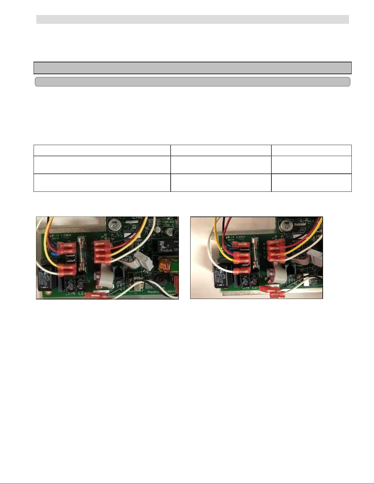
If the optional 863A Expansion Board has been installed along with the Pool Cover Switch, two
purifier % numbers will be displayed. The left one is the value when the pool cover is open and
the right is when the cover is closed.
Example of purifier adjustment display.
Example with the Retractable Pool Cover Open and the Temperature Display on.
Cell Status..... will show "ON" when chlorine is being generated.
Field will be blank when the cell is off.
Example with the Retractable Pool Cover Closed and Temperature Display off.
*This only applies to models that are equipped with the optional 863A Expansion Board and the
cover position switch is connected to the unit. See "Connecting the Retractable Cover Switch
(Option only available with purchase of #863A Expansion Board)" on page 33.
Caution: Regardless of retractable pool cover position, when the Boost feature is
activated the unit will increase chlorine production to 100% for 24 or 72 hours based on
the Boost time selected.
5.3.b 12/24 Hour Clock Display
A 12/24 Hour Clock that allows the user to set personal preference for time display. The Set
Time of Day feature can be set to display the correct time zone and / or adjustments for Daylight
Saving Time changes.
Page - 10
5.3.c Set Purifier Off
The Set Purifier Off feature will allow the Digital Nano/Nano+ to be programmed to delay
chlorine production if salt will not be added to the pool water for a specified amount of time, from
1-28 days. Or if there is a need to halt chlorine production for a set amount of time.
SECTION 6 - MAINTENANCE
6.1 Fuse Location and Ratings
WARNING - Failure to heed the following may result in permanent injury or death.
l ELECTRICAL SHOCK HAZARD – Turn off the electrical power to unit before servicing.
To inspect or service fuse, disconnect power and remove power center cover (see below for
location of fuse).
Ratings
BOARD FUSE SPECIFICATION DESCRIPTION
Main Power Board When Converted to 115V
75041A, 75043A, 75041A-xx, 75043A-xx
Main Power Board (Factory set as 230 Vac)
75041A, 75043A, 75041A-xx, 75043A-xx
250 Vac 2 Amp Slo Blo
250 Vac 1 Amp Slo Blo
AC Power Fuse for 115 Vac
Operation
Main AC Power Fuse for 230
Vac Operation
Location of Fuse
110V - 120V Configuration
Figure 3
220V - 240V Configuration
Figure 4
Page - 11
 Loading...