

Page 1

Salt Chlorine Generator for Residential Spas
SPA SANITIZING SYSTEM
TM
By AquaCal AutoPilot, Inc.
AquaCal AutoPilot, Inc.
2737 24th St. N.
St. Petersburg, FL 33713
Maximum output equivalent to 0.5 oz (15 grams) of free available chlorine per day.
One SpaPilot™ unit can treat a maximum of 600 gallons (2,200L) of spa water.
Installation /Operation Manual
PLEASE RETAIN OWNER'S MANUAL
FOR FUTURE REFERENCE
READ THE LABEL AND THE INST
2737 24th St. N.
St. Petersburg, FL 33713
IMPORTANT
ALLATION/OPERATION MANUAL BEFORE USING
800.786.7751
autopilot.com
#7843 SPAPILOT™ MANUAL 0607
Page 2
Zip Code
SPA SANITIZING SYSTEM
TM
State
Date Purchased
Serial #
City State Zip Code
WARRANTY REGISTRATION REPORT
Detach & mail within 14 days of purchase.
Street Address
Owner’s Name Phone Home Business Email
w
City
all
c Over the W
all
Serial Number is as Follows...
TM
Dealer (Source) Phone Fax
My SpaPilot™
Street Address
c In W
Model
Control Panel Serial #
Cell
Spa Volume: Gallons Liters
How often is your spa used? Daily Weekly Monthly Rarely
Age of Spa: New c Existing c If Existing: How many years ?
%
Page 3

AUTOPILOT
SPA SANITIZING SYSTEM
TM
The purchaser ("Customer") has purchased a "SpaPilot™" Spa Sanitizing System ("Unit") for use in Customer's
residential (not commercial) spa. Unit distributor, AquaCal AutoPilot, Inc., 2737 24th St. N., St. Petersburg, FL
33713 ("Manufacturer"), hereby provides a limited warranty to Customer as follows:
THREE (3) YEARS FROM THE DATE OF SALE, TO THE ORIGINAL PURCHASER, ON DEFECTS IN
M
ATERIALS AND WORKMANSHIPFOR THE SpaPilot™ POWER SUPPLY AND CELL. CUSTOMER MUST USE
S
paPilot™ SPA STARTER BLEND EXCLUSIVELY WITH THE SpaPilot™ ELECTROLYTIC GENERATOR, IN
O
RDER TO VALIDATE THIS WARRANTY. FAILURE TO USE THESE PRODUCTS SHALL RENDER THIS
W
ARRANTY NULL AND VOID. CUSTOMER SHALL BE RESPONSIBLE FOR ANY TRAVEL CHARGES
I
MPOSED BY WARRANTY CENTER OR SERVICING AGENT FOR TRAVEL. IN ADDITION, MANUFACTURER'S
L
IMITED WARRANTY IS FURTHER SUBJECT TO THE FOLLOWING CONDITIONS AND EXCLUSIONS:
1. This limited warranty is for the replacement of defective parts. Manufacturer reserves the right to replace
defective parts with new or refurbished parts at its sole discretion. All warranty replacement parts will carry
a 90 day warranty from date of installation, or the balance of the original warranty,
2
. This limited warranty is applicable only if the Unit is installed by an Authorized SpaPilot™ Dealer or its
d
esignee, a licensed electrician or by Customer in accordance with the installation procedures outlined in
t
he accompanying Installation Manual.
3. Spa water must be tested regularly in order to properly maintain its chemical balance. Excessive
chlorination is known to cause corrosion in spa metals. Failure of Customer to properly monitor the spa
water's balance can create a situation which could negatively affect the performance of the Unit and thus
void this limited warranty. Failure to comply with guidelines set forth in the Owner's Manual will void the
warranty. Customer releases and holds Manufacturer harmless from any and all claims stemming from their
failure to comply with these set guidelines.
Deterioration, discoloration or brittleness of spa surfaces, including but not limited to plaster, tile, and
4.
acrylic, can be caused separately by, or in combination with age, the environment, an imbalance in spa water
chemistry, improper installation, sunlight and other factors. Customer hereby disclaims all claims, and
releases Manufacturer from all claims for damages to any plaster, tile or acrylic surfaces in Customer's spa
by reason of the use and/or operation of the Unit. Customer represents and agrees that any claims which it
may assert against Manufacturer shall be limited to those which may be asserted under the foregoing
limited warranty.
5. Under no circumstances shall Manufacturer be liable for any loss or damage, whether direct, consequential
or incidental, arising out of the use or inability to use the Unit in Customer's spa. In addition, each spa has
its own individual sanitizer requirements. This limited warranty specifically states that this product will NOT
supply 100% of the sanitizer requirements for any specific residential spa. (Refer to Owner's Manual.)
6. This limited warranty does not apply to any injury, loss, damage, defect, or malfunction of the Unit or failure
to function resulting from any failure to operate or maintain the Unit in accordance with the directions
contained in the Owner's Manual or operating instructions provided by the Manufacturer; or any injury, loss,
damage, defect, or malfunction, or failure to function resulting from any accident, acts of God, alterations
in the Unit by anyone other than Manufacturer
omissions, failure or negligence by anyone other than Manufacturer including but not limited to such
damages or injuries to parts resulting from improper installation, or damage, defect or malfunction resulting
from defects in, failure or malfunction of, or negligence, abuse, or misuse with respect to equipment other
than the Unit, or any damage or loss of any nature whatsoever and personal injury caused due to the
presence of a foreign object in or about the spa.
7. This limited warranty is valid and enforceable only on Units purchased and installed in North America.
8. This limited warranty is applicable only if the Unit is purchased from an authorized SpaPilot™ Dealer. If
Customer is uncertain as to whether the seller of the Unit is an authorized SpaPilot™ Dealer, Customer
should call 800.786.7751 immediately after purchase for verification.
9. This limited warranty shall apply only to Customer as an original purchaser of the Unit from a SpaPilot
Dealer and shall not apply to any subsequent purchaser, assignee or other recipient of the Unit from
.
Customer
I0. No dealer, distributor or other similar person has any authority to make any warranties or
misrepresentations concerning Manufacturer's products, its Unit or to extend this warranty beyond the
express terms contained herein. Manufacturer assumes no responsibility for any warranties beyond the
expressed terms contained in this limited warranty
from any claims stemming from any unauthorized representations.
11.This limited warranty shall be void if Customer modifies the Unit in any respect including but not limited to
the use of parts other than genuine SpaPilot™ parts.
The foregoing limited warranty gives Customer specific legal rights which may vary by geographic area and
12.
accordingly, some of the listed conditions and exclusions may not apply to Customers living in certain
states.
13. These warranties set forth herein are in lieu of any other warranties, expressed or implied, including the
warranties of merchantability or fitness. Any such implied warranty imposed by law is limited in duration to
one (1) year from date of purchase.
14. Customer represents and agrees that any claims which it may assert against Manufacturer shall be limited
to those which may be asserted under the foregoing limited warranty.
15. Any dispute between Customer and Manufacturer will be settled by binding arbitration, conducted in
Calgary, Alberta, Canada.
AquaCal AutoPilot, Inc., 2737 24th St. N., St. Petersburg, FL 33713 • 800.786.7751
, or misuse, unreasonable use, tampering, abuse, acts,
. Customer releases and holds Manufacturer harmless
3-Year Limited Warranty
Residential Use Only
which ever is greater.
TABLE OF CONTENTS
Model: SP1 (OEM) and SP2 (over the wall)
Important Safety Instructions i
Health, General & Hyperthermia 1
Specifications 2
Section 1 Water Pretest & Preparation
1a System Sizing 3,4
1b Spa Water Preparation & Monitoring 5,6
Section 2 Installation Requirements
2a Power Supply & Cell Installation 7,8
2b Equipment Dimensions 9
Section 3 Start Up & Operation
3a Power Supply Functions 10,11
™
3b Start Up Sequence 11
Section 4 Troubleshooting
4a Troubleshooting 12
Appendix
Service Information 13
Water Pretest
Section 1
Installation
Section 2
Section 3
Start Up
Troubleshooting
Section 4
Appendix
Page 4

IMPORTANT SAFETY INSTRUCTIONS
READ AND FOLLOW ALL INSTRUCTIONS
EQUIPMENT RELATED, INSTALLATION AND GENERAL USE
Installation of all SpaPilot™ models
When installing and using the SpaPilot™ unit, basic safety precautions must always be followed, including
t
he following:
1
. Follow all aspects of the local and National Electrical Codes when installing the SpaPilot
2. D
uring installation, mount the SpaPilot™ unit to ensure the least amount of direct exposure to rain,
garden sprinkler water, direct sunlight or any corrosive environment.
3. WARNING - Risk of electrical shock. Plug the unit into an approved GFCI electrical outlet (110VAC ONLY).
I
t may also be connected directly onto the spa pack with a “patch cord”.
4. WARNING - Do not use spas or hot tubs unless all suction grates are installed to prevent body and hair
e
ntrapment.
5.DANGER - To reduce the risk of drowning from hair and body entrapment, install suction fittings with a
marked flow rate that equals or exceeds the flow rate on the equipment assembly.
WARNING - Install blower no less than 1 foot (30 cm) above the maximum water level to prevent water
6.
from contacting electrical equipment.
7. CAUTION - Maintain water chemistry in accordance with values set out on page 5.
Section 1
All field-installed metal components such as rails, ladders, drains, or other similar hardware within 10 feet
8.
Water Pretest
(3 m) of the spa or hot tub shall be bonded to the equipment grounding bus with copper conductors no
smaller than No. 8 AWG in the U.S.A. and No. 6 AWG in Canada.
™ unit.
To obtain service for your SpaPilot™ system, contact the Dealer/Service
Center listed below:
AquaCal AutoPilot, Inc.
2737 24th St. N.
St. Petersburg, FL 33713
800.786.7751 727.823.5642 Fax 727.821.7471
If warranty service is being requested, you must provide a copy of your registered
warranty card as proof of purchase. Warranty service cannot be performed without
this documentation.
WHEN CALLING FOR SERVICE - Please have the following information ready:
1. Power Supply Model:_____________________________________________
110V Models Only
1. WARNING - Risk of Electric Shock. Connect only to a grounding type receptacle protected by a groundfault-circuit-interrupter (GFCI). Contact a qualified electrician if you cannot verify that the receptacle is
protected by a GFCI. The conductors on the load side of the GFCI shall not occupy conduit boxes or
enclosures containing other conductors unless the additional conductors are also protected by a GFCI.
2. The GFCI must be tested before each use. With the SpaPilot™ unit operating, push the test button on the
GFCI. The SpaPilot™ unit should stop operating. Push the reset button. The SpaPilot
start to operate normally. If the GFCI fails to operate in this manner, there is a ground current flowing,
indicating the possibility of an electrical shock. Disconnect the power until the fault has been identified
and corrected.
3. WARNING -To reduce the risk of electric shock, replace damaged cords immediately.
4. WARNING -To reduce the risk of electric shock, do not use extension cords to connect unit to electric
supply; provide a properly located outlet.
5. Do not bury cord. Locate cord to minimize abuse from lawn mowers, hedge trimmers and other
equipment.
™ unit should now
General Use
1. WARNING - To reduce the risk of injury do not permit children to use this product unless they are closely
supervised at all times. Children should not use spas or hot tubs without permanent adult supervision.
2. WARNING - Risk of accidental drowning. Extreme caution must be exercised to prevent unauthorized
access by children. To avoid accidents, ensure that children cannot use a spa or hot tub.
3. DANGER - To reduce the risk of injury, do not remove the suction grates. Never operate a spa or hot tub if
the suction grates are broken or missing. Never replace a suction grate with one rated less than the flow
rate marked on the equipment assembly.
4. DANGER - Risk of electrical shock. Do not permit any electrical appliance, such as a light, telephone,
radio, or television, within 5 feet (1.5 m) of spa or pool.
5. To avoid injury, exercise care when entering or exiting the spa or hot tub.
2. Chlorine Cell Serial Number:_______________________________________
(Located on top of cell, stamped in plastic)
3. Installation Date: MM:___________DD:_________YY:__________________
4. Warranty Registration Number:_____________________________________
Appendix
i
13
Page 5

Section 4 a
SpaPilot™
Troubleshooting
HEALTH, GENERAL AND HYPERTHERMIA
General: WARNINGS - To reduce the risk of injury:
PROBLEM / CAUSE SOLUTION
1. Insufficient sanitizer production.
A. The test kit reagents or test strips are old or expired A. Retest with new reagents or test strips
B. The unit is set too low in relation to the sanitizer demand B. Increase the feed rate on the output dial.
C. Sanitizer loss due to intense sunlight exposure. C. Check the stabilizer level and add cyanuric Acid if
D
. The body of water being sanitized leaks. D. Repair the leak and rebalance the water being sanitized.
E
. Low salt. E. Check the residual salt level and add if necessary.
2. Scale build-up within the cell.
A. The water being sanitized contains high pH, A. Calculate Langelier's Index to assure balanced water. (See
alkalinity and calcium hardness. page 5). Adjust the water chemistry and mix 1 part muriatic
3. DC Plug is burned.
A. The cell cord plug is not securely pushed onto the power A. Ensure that the cell cord plug is pressed completely on the
supply allowing moisture to seep into the plug. power supply. Also check GFCI circuit and reset.
B. Completely failed cell. B. Replace the cell.
4. Premature cell failure.
A. Abnormally high cell usage due to an insufficient CYAlevel. A. Check the stabilizer level and add cyanuric acid if needed.
B. Debris in Cell. B. Inspect cell monthly and clean debris if required.
5. White flakes in the water.
A. This occurs when excessive calcium hardness is present in A. Monitor the pH and adjust if necessary.
the water being sanitized. This should cease after a few days. (Refer to the Spa Water Preparation section, page 5.)
6. No solid green "OK" light.
A. Incoming 110 VAC power not present. A. Ensure that the SpaPilot™ circuit breaker is set to "ON" and
7. Rapid Green Flash - (Two flashes per second)
Section 4
Troubleshooting
A. The cell is scaled. A. Clean cell and re-install.
B. The cell DC cord is disconnected B. Reconnect the DC cord properly.
C. Low salt. C. Check the residual salt level and adjust if necessary.
D. The unit is not reversing polarity. D. Return the Power Supply to your retailer for service or
E. Possible cell failure. E. Return Power Supply and Cell to your retailer for
F. Very cold spa water. F. Raise temperature to normal operating range (Max
needed. (Refer to the Cyanuric Acid Needed for 75 PP
section, page 6.)
(Refer to the Spa Water Preparation section, page 5.)
(Refer to the Salt Requirements Needed for 2000 ppm
section, page 6)
acid to 4 parts water. Allow the cell to soak in this solution
for no longer than 15 minutes. Repeat if necessary. Rinse
with fresh water and re-install. Dilute spa water with fresh
water if necessary.
(Refer to the Cyanuric Acid Needed for 75 PPM, page 6)
functional.
B. Check GFCI circuit and reset.
(Refer to the salt requirements needed for 2,000 ppm section,
page 6).
replacement.
testing/servicing.
C)
°
F/40
°
104
1
. People using medications and/or having an adverse medical history should consult a physician
b
efore using a spa or hot tub.
2
. People with infectious diseases should not use a spa or hot tub.
3
. The maximum spa water usage temperature is 104°F (40°C). Duration in spa water at 104°F (40°C)
s
hould not exceed 15 minutes. Lower water temperatures are recommended for young children and
w
hen spa use exceeds 10 minutes.
4. Water temperature in excess of 100°F (38°C) may be dangerous to your health.
5
. Pregnant or possibly pregnant women should consult a physician before using a spa or hot tub.
6. Since excessive water temperatures have a high potential for causing fetal damage during the
f
irst trimester of pregnancy, pregnant or possibly pregnant women should limit the spa water
temperatures to 100°F (38°C).
7. Before entering a spa or hot tub, the user should measure the water temperature with an
accurate thermometer since the tolerance of water temperature regulating devices varies.
8. The use of alcohol, drugs or medication before, or during, spa or hot tub use may lead to
unconsciousness with the possibility of drowning.
9. Obese persons and persons with a history of heart disease, low or high blood pressure,
circulatory system problems, or diabetes should consult a physician before using a spa/hot tub.
10. Persons using medication should consult a physician before using a spa or hot tub since
some medication may induce drowsiness while other medication may affect heart rate,
blood pressure and circulation.
11. Do not use a spa or hot tub immediately following strenuous exercise.
12. Prolonged immersion in a spa or hot tub may be dangerous to your health.
Hyperthermia
WARNING -The use of alcohol or drugs can greatly increase the risk of fatal hyperthermia in hot tubs
and spas.
Consult your spa/hot tub manufacturer's manuals for the proper adjustment of water temperature.
Prolonged immersion in hot water may induce hyperthermia. Hyperthermia occurs when the internal
temperature of the body reaches several degrees above the normal body temperature of 98.6°F (37°C).
Hyperthermia symptoms include drowsiness, lethargy, and an increase of internal body temperature.
The effects of hyperthermia include:
1. unawareness of impending hazard
2. failure to perceive heat
failure to perceive the need to exit the spa/hot tub
3.
4. physical inability to exit spa
5. fetal damage in pregnant women
6. unconsciousness and danger of drowning
Water Pretest
Section 1
12
1
Page 6
Specifications
SPA SANITIZING SYSTEM
TM
Equipment Start-Up Sequence
Section 3 b
SpaPilot™
SpaPilot™
INPUT : 105 - 125 VAC, 50/60 Hz, 0.5 amp
O
UTPUT: 5.0 VDC, 300 mA (104°F/40°C)
SpaPilot™ Model SP1 Cell: Maximum output equivalent to 0.5 oz (15 grams) of free available
N
OTE: The SpaPilot™ unit is designed to provide a chlorine residual whenever the spa IS NOT in use.
W
ith an average residential spa, this "non-use" time represents 95% to 99% of each day.
Supplemental sanitizer/oxidizer should be added before and/or after EACH spa use, to maintain 3-5
ppm (mg/L) of free available chlorine/bromine. For use in residential spas only.
CONVECTION: The SpaPilot™ system works in a convection mode, which is independent of the main
circulation pump. Rather
As the cell is energized to generate chlorine, bubbles will appear and is normal. If the cell is removed
Section 1
from the spa, chlorine generation is halted.
Water Pretest
chlorine per 24 hours @ max. dial setting of 100%
, the convection cell must be submerged underwater for proper operation.
Reverse Polarity Function:
Automatic Self Cleaning Feature
The Reverse Polarity Function is designed to automatically clean the cell blades, maximizing the cell’s
ability to manufacture chlorine or bromine. This feature is enabled only when the power is on and the
L.E.D. light displays a solid GREEN color. The unit reverses polarity after the first hour of run time; then
every three hours from that point on.
Before operating the SpaPilot™ System, perform the following steps to ensure proper installation
a
nd operation:
A. Turn ON all circuit breakers to the spa equipment. B. Turn on jet pump. C. Add required type(s)
a
nd amount of salt to spa. Broadcast over the surface and allow salt to COMPLETELYdissolve (15
- 20 minutes). D. Place the cell in the spa (bottom of footwell). E. Plug the Power Supply into a
1
10VAC GFCI protected outlet and set the feed rate dial to 100%.
The following indicators should display: A series of green flashes for 5 seconds, followed by a
solid green light. If this sequence does not occur please refer to the Troubleshooting Guide on
p
age 12 for further assistance.
N
OTE: Be sure to test the chlorine level for the next few days and properly adjust the chlorine
output dial as outlined on page 4 of this manual.
D
O NOT EXCEED RECOMMENDED CHLORINE LEVELS!
Make the required adjustment and allow the spa to react to this change for a minimum of 2 days.
After 2 days, retest the spa water and make any further "small" adjustments as required, until the
SpaPilot™ unit maintains an adequate Free Available Chlorine residual (during the “non-use”
times).
Section 3
Start Up
2
11
Page 7

Section 3 a
SpaPilot™
SpaPilot™ Power Supply Functions
System Sizing for Spas
Section 1 a
SpaPilot™
A. WHEN POWER IS FIRST TURNED ON:
The light will flash GREEN slowly (1 flash per second) for approximately 5 seconds while the
S
paPilot™ unit self-tests.
B
. OK:
If your SpaPilot™ unit is operating properly, this indicator will display solid GREEN. This indicates that
power is being delivered from the SpaPilot™
b
eing sanitized by Hypochlorous Acid (chlorine). NOTE: While sanitizer is being produced, bubbles
can be seen coming from the cell blades!
C. CHECK SYSTEM:
T
he light will flash GREEN rapidly (2 flashes per second) to indicate a component problem or failure.
For further explanation of this indicator,
on page 12.
Output Control
The Output Control Dial is a percentage timer that regulates the amount of "on" time the system
requires to maintain the chlorine residuals as indicated on page 5 of this manual.
The output is regulated according to the setting of this dial. Remember the unit operates with
convection. It operates independently from your filter pump run time.
Any interruption of power will cause the current memory cycle to reset itself when power is
NOTE:
restored.
Start Up
Section 3
unit to the cell and is producing sanitizer and your spa is
please refer to the Troubleshooting Guide beginning
50 %
25 % 75 %
0 %
100 %
System Sizing
Use these three formulas to calculate the volume of water in the spa:
R
ectangular: Length(Ft) x Width(Ft) x Average Depth(Ft) x 7.5 = Total U.S. Gallons
Round: 3.14 x Radius(Ft) x Radius(Ft) x Average Depth(Ft) x 7.5 = Total U.S. Gallons
F
ree Form: Average Length(Ft) x Average Width(Ft) x Average Depth(Ft) x 7.5 = Total U.S. Gal.
Length(M) x Width(M) x Average Depth(M) x 1000 = Total Litres
3
.14 x Radius(M) x Radius(M) x Average Depth(M) x 1000 = Total Litres
A
verage Length(M) x Average Width(M) x Average Depth(M) x 1000 = Total Litres
IMPORTANT CONCEPTS
SpaPilot™ System Production Capacity
1. Sanitizer Demand
The rate at which sanitizer is
variables. Since these variables can vary widely from spa to spa and season to season, precise
prediction of the sanitizer
thumb are provided for SpaPilot™ System sizing.
THE VARIABLES ARE:
1. V
olume and surface area of the spa being sanitized.
verage water temperature maintained: As the temperature of the water increases, the sanitizer
A
2.
demand
also increases. As the temperature of the water decreases, the sanitizer
decreases. When this happens, the output dial should be decreased to compensate for this lower
demand
(which will also protect your equipment from excessive levels of sanitizer).
3. Cyanuric acid level maintained: This chemical, when added to your outdoor spa water, significantly
inhibits sanitizer depletion from exposure to sunlight. Cyanuric acid also inhibits corrosion if your
spa is equipped with any metal components. Minimum levels or better must
that the sanitizer being produced is protected from UV breakdown.
Bather load
4.
5. Amount of direct sunlight / UV exposure
vulnerable to increased sanitizer loss and algae growth. Indoor or screened spas have less sanitizer
demand.
6. Exposure to vegetation and airborne debris
nitrate levels (urine, bird droppings, fertilizer, well water, etc.) greatly contribute to increased
sanitizer demand.
Chemical dilution: Virtually all spa chemicals experience dilution through rainfall, adding of fresh
7.
make-up water due to evaporation, splash-out, filter backwashing, leaks, etc. When freshwater is
added, sanitizer
8. Main filter pump runtime and your spa's circulation patterns
features operated by the filter pump can directly affect sanitizer
runtime and/or output dial may need to be increased to satisfy this higher
: As the bather load increases, the sanitizer
consumed
demand
demand
increases for a brief period.
in any spa depends on the relationship of
for any one spa is difficult.
: Spas exposed to larger amounts of direct sunlight are more
: Dense landscaping near the spa, along with increased
At the end of this section, rules of
demand
: Waterfalls/Fountains and other water
also increases.
demand
eight major
demand
be maintained to ensure
. The main filter pump
demand.
also
W
ater Pretest
Section 1
10
3
Page 8
Section 1 a
SpaPilot™
N
OTE: The SpaPilot™ unit is designed to provide a chlorine/bromine residual whenever the spa IS
NOT in use. With an average residential spa, this "non-use" time represents 95% to 99% of each day.
S
upplemental sanitizer/oxidizer should be added before and/or after EACH spa use, to maintain 3-5
ppm (mg/L) of free available chlorine/bromine. For use in residential spas only.
System Sizing for Spas (Continued)
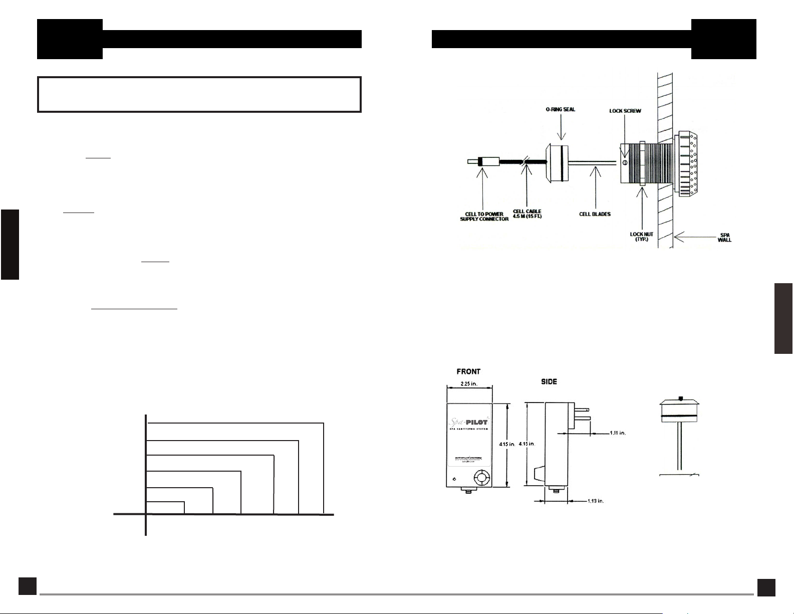
2. Sanitizer Production/System Sizing/"Rules of Thumb"
Dimensions - Power Supply & Cell
Section 2 b
SpaPilot™
While sanitizer
i
n your spa, the following "rules of thumb" will assist you in properly selecting the correct SpaPilot™ feed
rate dial setting.
1. A SpaPilot™ power supply with cell , operated at maximum output (100%), at 1800-2000 ppm salt
residual will produce 0.5 oz (15 grams) of free available chlorine in 24 hours of continuous operation.
This amount of chlorine could satisfy up to 600 U.S. gallons (2,200 L) of spa water, depending on
the 8 demand variables for sanitizer.
demand
varies beyond precise prediction, or you desire a higher or lower sanitizer residual
Normal System Sizing Guide
Section 1
The sizing criteria below reflects
Water Pretest
Sanitizing "demand" varies from one spa to another. The chart below provides approximate feed rate dial
settings required to maintain adequate chlorine (3.0 - 5.0 ppm) or bromine residuals (3.0 - 5.0 ppm) during
"non-use" periods, based on spa volume.
NOTE: Establishing the exact feed rate dial setting is required. To maintain 3.0-5.0 ppm chlorine or bromine
residual, during “Non-Use Spa T
should be “marked” on the power supply as this will become the permanent setting for your
particular spa.
For proper sanitation, spa must be completely drained periodically. The number of days between
COMPLETE SPADRAINAGE is equal to the volume of spa water in gallons, divided by 2.639 times the
maximum number of daily spa users. Refill spa with water and repeat the start-up procedure.
Approximate
Feed Rate Dial
Settings
30%
25%
20%
15%
10%
5%
"normal"
conditions based on field experience and proper operation.
ime” will require trial and error adjustments. Once set, this setting
Diagram 2
Model SP1
UNIT WITH "IN WALL" FACTORY INSTALLED CELL.
Installation
Section 2
Gallons
Litres
4
100 200 300 400 500 600
375 750 1125 1500 1900 2200
Spa Size
9
Page 9
Section 2 a
SpaPilot™
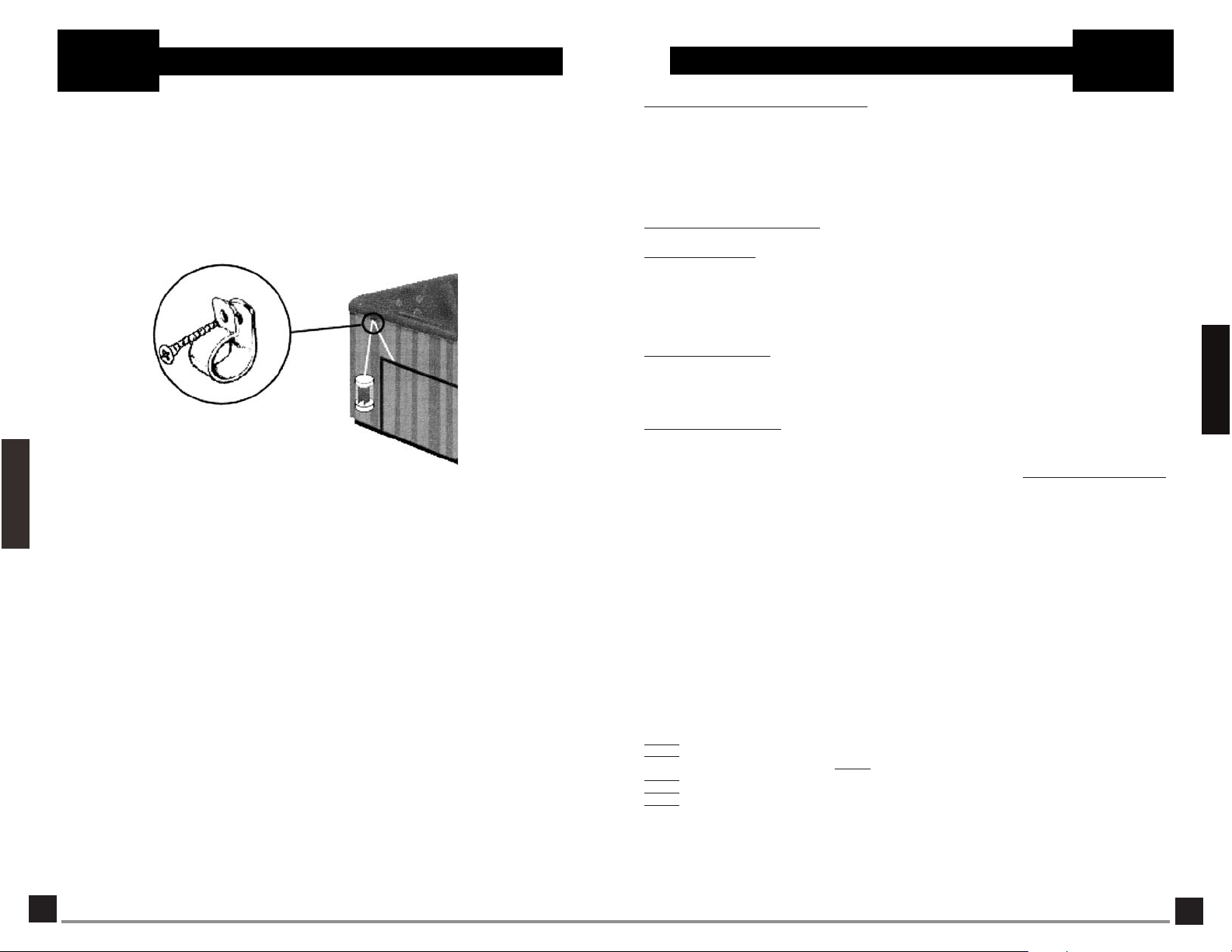
UNIT WITH CELL ATTACHED FOR "OVER THE WALL"
INSTALLING THE "P" CLIP:
Section 2
Position the DC cable into the "P" clip. Using the stainless steel screw provided, fasten the
Installation
"P" clip to the top of the spa skirt, just below the acrylic lip. Before tightening the screw and
locking the cable into place, adjust the length of the DC cable so that the cell remains
approximately 1" above the floor or ground when hanging freely. The cell can now be put into
and taken out of the spa without damage.
NOTE: The SpaPilot™ over the wall cell should be removed whenever the spa is in use.
installing the "P" clip provided, simply hang the cell outside the spa as indicated in the figure
above, during spa use.
Power Supply and Cell Installation (Continued)
Model SP2
RETROFIT INSTALLATION.
After
Spa Water Preparation & Monitoring
1 - Proper Water Balance Requirements:
STEP
P
roper SpaPilot™ System operation is dependent on proper spa water conditions. Manually balance the spa
water chemistry to meet all suggested ranges of water balance factors listed below before start-up of the
SpaPilot™ unit. From that point forward your SpaPilot™ System will assist you in keeping your water chemistry
f
actors in balance.
BEFORE START UP, MAKE SURE THE SPA WATER MEETS THE FOLLOWING REQUIREMENTS:ALL WATER
B
ALANCE FACTORS SHOULD FALL WITHIN LANGELIER'S SATURATION INDEX. WE RECOMMEND A VISIT
TO YOUR LOCAL SPA PROFESSIONAL.
S
™ S
paPilot
S
TEP
STEP
metal components in contact with spa/hot tub water. Staining and premature failure of heaters, filters, and other
metal components will be the result. Do not exceed recommended sanitizer ranges. NOTE: Standard (DPD) pool
water test kits do not read chlorine/bromine levels above approximately 5.0 ppm. Test reagents, at high levels,
can be bleached out and return to a clear liquid.
STEP
times. Low salt levels will activate a rapid green flash CHECK SYSTEM light and may stop sanitizer generation.
Salt levels can be determined by using the SpaPilot™ Salt Test Strips included with your starter kit. The
amount of SpaPilot™ Spa Starter Blend required depends on the size of the spa/hot tub. Use the chart on
the next page to determine the amount of salt to add, in pounds or kilograms, for a new spa/hot tub start up.
Also test your make up water for its level of salt and compare it with the charts on the next page. Before
adding SpaPilot™ Spa Starter Blend to a spa/hot tub for the first time, turn your circulation pump on and your
SpaPilot™ unit OFF, then pour SpaPilot
NOTE: Homeowners with water softening/treatment equipment, which utilize salt, may already have substantial
levels of salt in their drinking water. So before adding this water to your spa, test the level of salt, then
determine the amount of SpaPilot™ Spa Starter Blend still needed to be added to bring the level up to the
suggested 2000 ppm start-up level. Before adding any make-up water to your spa, you should pre-test the
water for pH, and total alkalinity and adjust these levels before they become too excessive. Your starter kit
includes 4-in-1 SpaPilot™ Test Strips for this purpose.
NOTE: Maintaining constantly high levels of salt chlorine or bromine above the recommended range can
contribute to corrosion of the pool equipment. Salt levels exceeding the recommended concentration can be
reduced by diluting the spa water with fresh water. NOTE: Heavy uses of the spa (excessive contamination) may
require longer recovery times (a return to a minimum of 3 ppm chlorine or bromine). Recovery time may be
reduced by adding a shock compound to the water. Follow instructions of the shock compound being used.
MANUAL CLEANING OF CELLS
In normal conditions the SpaPilot™ unit should not require manual cleaning. If manual cleaning is required,
check water chemistry for possible imbalances or call the factory for consultation, and use the following
procedure:
STEP
STEP
STEP
STEP
STEP
NOTE: DO NOT try to remove any scale from cell blades with any tools. This may scratch or damage the coating
on the blades and will VOID WARRANTY. The electrolytic cell has a life expectancy of 2 to 4 years under typical
conditions of use. When replacing the cell, only use replacement cells having a label that clearly states that it
is a replacement cell for the chlorine generating device SpaPilot™.
ystem Required Ranges(and periods for testing water for these water balance factors.)
2
- Daily Checks:
1) Free Available Chlorine = 3.0 - 5.0 ppm 5) Salt Residual 1800-2200 ppm
2
) Calcium Hardness 150 - 200 ppm 6) Langelier's Index (water balance)+0.3 or -0.3
3) Total Alkalinity 80 - 120 ppm 7) pH 7.2-7.8 NOTE: (Check expiration date of the
4) Cyanuric Acid 30-100 ppm (Outdoor) test kit as test results may be inaccurate if used
3 - Monthly Checks: CAUTION: Excessive Free Available Chlorine (> 5.0 ppm) causes corrosion of any
AVOID HIGH SANITIZER LEVELS!
4 - Salt Requirements: It is important that a suggested salt level of 1800-2200 ppm be maintained at all
™ Spa Starter Blend around the perimeter of the spa.
1 - Disconnect the cell cord from the SpaPilot™ unit and remove the cell.
2 - Using a bucket, add 1 part muriatic acid to 4 parts of water. PUT WATER IN BUCKET FIRST!
CAUTION: Always add acid to
3 - Submerge the cell in the solution.
4 - After foaming stops, or up to 15 minutes, remove the cell. Rinse with fresh water.
5 - If cell blades still have white crusty scale deposits on them, repeat the process, not to exceed 15
minute intervals.
WATER
, never water to acid.
after that date.)
Section 1 b
SpaPilot™
Water Pretest
Section 1
8
5
Page 10
Section 1 b
SpaPilot™
POUNDS OF SpaPilot™ SPASTARTER BLEND
Salt Level Spa Volume in US Gallons
B
efore
A
ddition
0
300 ppm 1.5 3.0 4.5 6.0 7.5 9.0
6
00 ppm 1.3 2.6 4.0 5.3 6.6 7.9
9
00 ppm 1.1 2.3 3.5 4.6 5.8 6.9
1200 ppm 1.0 2.0 3.0 4.0 5.0 6.0
1600 ppm .80 1.6 2.3 3.1 3.9 4.7
1
900 ppm .60 1.2 1.8 2.4 3.0 3.6
R
EQUIRED FOR 2000 PPM
100 200 300 400 500 600
ppm 1.6 3.3 5.0 6.6 8.3 9.9
Salt Requirements Needed for 2000 PPM
NOTE: Turn SpaPilot™ unit off before adding sodium chloride and other chemicals,
and wait until complete dissolution before turning it on.
Section 1
Water Pretest
Section 1 b
SpaPilot™
KILOGRAMS OF SpaPilot™ SPA STARTER BLEND
R
EQUIRED FOR 2000 PPM RESIDUAL
S
alt Level Spa Volume in Liters
Before
Addition
0
300 ppm .66 1.3 2.0 2.6 3.3 3.8
600 ppm .58 1.2 1.7 2.3 2.9 3.4
9
00 ppm .50 1.0 1.5 2.0 2.5 2.9
1200 ppm .
1
600 ppm
1900 ppm .27 .53 .79 1.0 1.3 1.5
375 750 1125 1500 1900 2200
ppm .72 1.4 2.2 2.9 3.7 4.3
44 .85 1.3 1.7 2.2 2.5
.34 .66 1.1 1.4 1.8 2.1
Cyanuric Acid needed for 75 PPM
Power Supply and Cell Installation
P
ower Supply
The Power Supply should be plugged into a 110VAC GFCI protected outlet and preferably away
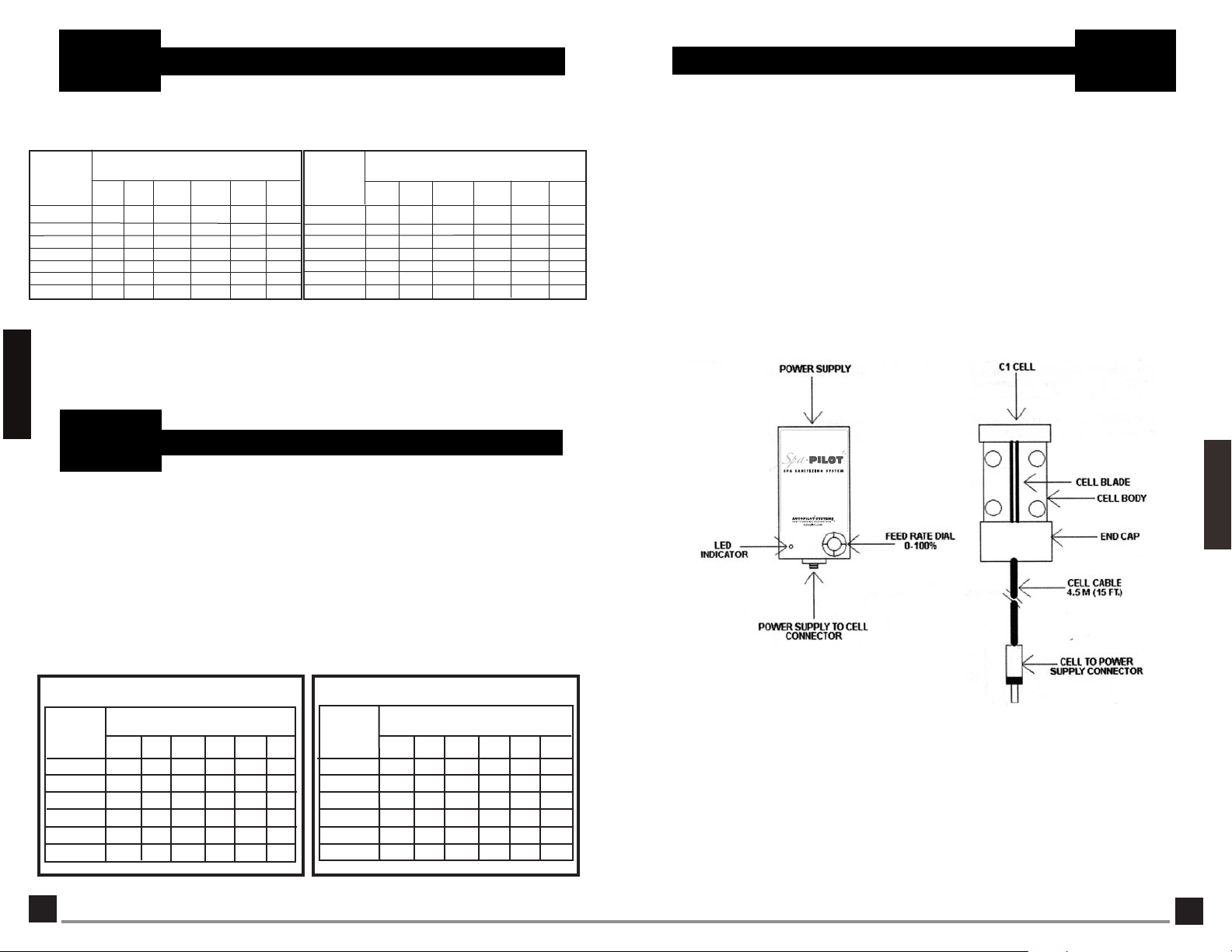
from direct exposure to sunlight. The Power Supply is equipped with a 15 ft. (4.5m) DC cell cord.
The unit comes complete with one of two cell types.
-
For existing spas, the SpaPilot™ unit will be provided with a quick disconnect cell cord for
simple over the wall installation. The cell should be placed into the footwell of the spa. (Diagram
1)
-
Where SpaPilot™ unit is a factory installed option, the cell will be glued into a standard spa
fitting and installed directly into the wall of the spa. The In-wall model includes a DC cell cord
with spade connectors to allow for future servicing of the Power Supply. (Diagram 2, see page 9)
Section 2 a
SpaPilot™
Installation
Section 2
Cyanuric
Cyanuric acid, CY
sunlight. Maintain CYAconcentrations between 60-80 ppm by diluting with fresh water. Regulations may exist
regarding use of Cyanuric acid in spas; please consult with your spa professional. Use the chart below to
determine the amount of Cyanuric acid needed. Test water with a test kit that includes CYA testing, then use the
chart below to determine the amount to add. Note: Indoor or bromine spas do not require the addition of CYA.
Acid/Stabilizer/Conditioner (Required with uncovered outdoor spas only)
A, (also known as stabilizer or conditioner) prevents rapid breakdown of chlorine by direct
OUNCES OF CYANURIC
CYA Level US Gallons
Before
Addition 100 200 300 400 500 600
0 ppm 1.0 2.0 3.0 4.0 5.0 6.0
10 ppm .87 1.7 2.6 3.5 4.4 5.3
25 ppm .66 1.3 2.0 2.6 3.3 3.9
40 ppm .47 .95 1.4 1.9 2.4 2.9
50 ppm .33 .66 1.0 1.3 1.6 2.0
60 ppm .20 .40 .60 .80 1.0 1.2
75 PPM RESIDUAL
ACID NEEDED FOR
Spa Volume in
CYA Level
Before
Addition
0 ppm 28.0 56.0 84.0 112 142 164
10 ppm
25 ppm
40 ppm 13.0 26.0 39.0 52.0 69.9 76.3
50 ppm 9.5 19.0 28.0 38.0 48.1 55.7
60 ppm
GRAMS OF CYANURIC
FOR 75 PPM RESIDUAL
375 750 1125 1500 1900 2200
49.0
24.0
37.0
19.0
11.0 17.0 24.0 30.4 35.2
5.5
ACID NEEDED
Spa Volume in
Liters
73.0 98.0 124 144
56.0
75.0 95
10
1
6
Diagram 1
Model SP2
7
 Loading...