

Page 1

User Manual
Vision Sensors
VG Series
Thank you for purchasing an Autonics product.
This user manual contains information about the product and its proper use,
and should be kept in a place where it will be easy to access.
www.autonics.com
Page 2

ii © Copyright Reserved Autonics Co., Ltd.
Page 3

Preface
Preface
Thank you for purchasing an Autonics product.
This user manual contains information about the product and its proper use, and should be kept
in a place where it will be easy to access.
© Copyright Reserved Autonics Co., Ltd. iii
Page 4

User Manual Guide
User Manual Guide
Please familiarize yourself with the information in this manual before using the product.
This manual provides detailed information on the product's features. It does not offer any
guarantee concerning matters beyond the scope of this manual.
This manual may not be edited or reproduced in either part or whole without permission.
This programming manual is not provided as part of the product package. Please visit our
home-page (www.autonics.com) to download a copy.
The manual's content may vary depending on changes to the product's software and other
unforeseen developments within Autonics, and is subject to change without prior notice.
Upgrade notice is provided through our homepage.
We contrived to describe this manual more easily and correctly. However, if there are any
corrections or questions, please notify us these on our homepage.
iv © Copyright Reserved Autonics Co., Ltd.
Page 5
User Manual Symbols
User Manual Symbols
Symbol Description
Supplementary information for a particular feature.
Failure to follow instructions can result in serious injury or death.
Failure to follow instructions can lead to a minor injury or product damage.
※1
An example of the concerned feature's use.
Annotation mark.
© Copyright Reserved Autonics Co., Ltd. v
Page 6
Safety Considerations
Safety Considerations
Following these safety considerations will ensure the safe and proper use of the product
and help prevent accidents, as well as minimizing possible hazards.
Safety considerations are categorized as Warnings and Cautions, as defined below:
Warning
Caution
Failure to follow the instructions may lead to a serious injury
or accident.
Failure to follow the instructions may lead to a minor injury
or accident.
Fail-safe device must be installed when using the unit with machinery that may cause
serious injury or substantial economic loss. (e.g. nuclear power control, medical equipment,
ships, vehicles, railways, aircraft, combustion apparatus, safety equipment, crime/disaster
prevention devices, etc.)
Failure to follow this instruction may result in personal injury, fire, or economic loss.
Do not use this product for protecting human body or part of body.
Do not see light LED directly or direct beam at person.
Failure to follow this instruction may result in damage on eyes.
Do not connect, repair, or inspect the unit while connected to a power source.
Failure to follow this instruction may result in fire.
Check connections and connect cables.
Failure to follow this instruction may result in fire.
Do not disassemble or modify the unit.
Failure to follow this instruction may result in fire.
Use the unit within the rated specifications.
Failure to follow this instruction may result in fire or product damage.
Use dry cloth to clean the unit. Do not use water or organic solvent when cleaning the unit.
Failure to follow this instruction may result in fire.
Do not use the unit where flammable/explosive/corrosive gas, humidity, direct sunlight,
radiant heat, vibration, impact or salt may be present.
Failure to follow this instruction may result in fire or explosion.
Keep metal chip, dust and wire residue from flowing into the unit.
Failure to follow this instruction may result in fire or product damage.
The above specifications are subject to change and some models may be discontinued
without notice.
Be sure to follow cautions written in the instruction manual, user manual and the
technical descriptions (catalog, homepage).
vi © Copyright Reserved Autonics Co., Ltd.
Page 7

Caution during Use
Caution during Use
Follow instructions in Cautions during Use. Otherwise, it may cause unexpected accidents.
24VDC power supply should be insulated and limited voltage/current or Class 2, SELV
power supply device.
In order to avoid malfunction from static electricity or noise, ground shield wire of the power
I/O cable.
Do not disconnect the power supply while setting operation or saving set information.
It may cause data loss.
Do not disconnect the power supply while updating firmware.
It may cause product damage.
Keep optical section of the sensor away from the contact with water, dust and oil.
It may cause malfunction.
When changing the light or filter, use the assembly tool and observe installation instruction.
When the sensor is not used for a long time, separate the power cable to store.
When connecting network, connection must be operated by technical expert.
In the following case, disconnect the power supply immediately. It may cause fire or product
damage.
① When water or foreign substance is detected in the product
② When the product is dropped or case is damaged
③ When smoke or smell is detected from the product
Do not use the product in the place where strong magnetic field or electric noise is
generated.
This unit may be used in the following environments.
① Indoor (in the environment conditions in specifications)
② Altitude max. 2,000m
③ Pollution degree 2
④ Installation category Ⅱ
© Copyright Reserved Autonics Co., Ltd. vii
Page 8

Caution during Use
viii © Copyright Reserved Autonics Co., Ltd.
Page 9

Table of Contents
Table of Contents
Preface .............................................................................................................................iii
User Manual Guide ......................................................................................................... iv
User Manual Symbols ...................................................................................................... v
Safety Considerations ..................................................................................................... vi
Caution during Use ......................................................................................................... vii
Table of Contents ............................................................................................................ ix
1 Product Instruction ................................................................................... 11
1.1 Features ............................................................................................................. 11
1.2 Accessory and sold separately .......................................................................... 12
1.2.1 Overall configuration diagram .................................................................... 12
1.2.2 Accessory ................................................................................................... 13
1.2.3 Sold separately ........................................................................................... 14
1.3 Ordering Information .......................................................................................... 16
1.4 Unit Description ................................................................................................. 17
2 Specifications ............................................................................................ 19
3 Dimensions ................................................................................................ 21
3.1 Body ................................................................................................................... 21
3.2 Bracket ............................................................................................................... 21
3.2.1 Bracket A (BK-VG-A) .................................................................................. 21
3.2.2 Bracket B (BK-VG-B) ................................................................................. 21
3.3 Cable .................................................................................................................. 22
3.3.1 Power I/O cable .......................................................................................... 22
3.3.2 Ethernet cable ............................................................................................ 22
4 Connections .............................................................................................. 23
4.1 Power I/O Cable (M12 12-pin connector) .......................................................... 24
4.1.1 Input ........................................................................................................... 25
4.1.2 Output (OUT0 to OUT3) ............................................................................. 25
4.2 Ethernet Cable (M12 8-pin/RJ45 connector) ..................................................... 26
5 Installation ................................................................................................. 27
5.1 Working Distance and FOV by Effective Focal Length ..................................... 28
5.2 Installation of Vision Sensor .............................................................................. 29
5.3 Focus Adjustment .............................................................................................. 29
5.4 Replacement of Light and Filter ......................................................................... 30
5.4.1 Replacement of color filter or polarizing filter ............................................. 30
5.4.2 Replacement of light .................................................................................. 31
6 Vision Sensor Program [Vision Master] .................................................. 33
6.1 Overview ............................................................................................................ 33
6.2 Vision Master Work Flow ................................................................................... 37
6.2.1 Setting mode .............................................................................................. 37
© Copyright Reserved Autonics Co., Ltd. ix
Page 10

Table of Contents
6.2.2 Operation mode .......................................................................................... 38
6.3 Installation of Vision Master ............................................................................... 39
6.3.1 System requirements ................................................................................. 39
6.3.2 Installation of the program .......................................................................... 39
6.3.3 Installation folder structure ......................................................................... 43
6.3.4 Removal of the program ............................................................................. 43
6.3.5 Network setting ........................................................................................... 44
6.4 Start and Exit ..................................................................................................... 47
6.4.1 Start ............................................................................................................ 47
6.4.2 Exit .............................................................................................................. 47
6.5 Vision Master Screen Layout ............................................................................. 48
6.5.1 Menu ........................................................................................................... 50
6.5.2 Toolbar ........................................................................................................ 53
6.6 Setting Menu ...................................................................................................... 57
6.6.1 Network ...................................................................................................... 57
6.6.2 Camera ....................................................................................................... 60
6.6.3 Input ............................................................................................................ 66
6.6.4 Output ......................................................................................................... 71
6.6.5 Work Group ................................................................................................ 75
6.6.6 Inspection ................................................................................................... 79
6.7 Inspection........................................................................................................... 82
6.7.1 Alignment ................................................................................................... 83
6.7.2 Brightness .................................................................................................. 87
6.7.3 Contrast ...................................................................................................... 89
6.7.4 Area ............................................................................................................ 91
6.7.5 Edge ........................................................................................................... 93
6.7.6 Shape comparison ..................................................................................... 96
6.7.7 Length......................................................................................................... 98
6.7.8 Angle ........................................................................................................ 100
6.7.9 Diameter ................................................................................................... 102
6.7.10 Object counting ........................................................................................ 105
6.7.11 Color identification .................................................................................... 108
6.7.12 Area of color .............................................................................................. 111
6.7.13 Object of color counting............................................................................ 114
7 Settings .................................................................................................... 117
7.1 Simulator .......................................................................................................... 11 8
7.2 Device (Vision Sensor) .................................................................................... 121
8 Troubleshooting ...................................................................................... 125
x © Copyright Reserved Autonics Co., Ltd.
Page 11

1 Product Instruction
1.1 Features
VG series, vision sensor, is the light and sensor integrated type which has 13 types of inspection
functions, so that it can be applied and utilized for various environment and condition. Before
applying to actual environment to utilize, using simulator can realize inspection.
Since it is available to set 32 work groups and 64 inspection items for each work group, vision
sensor can flexibly response to the change of work environment.
Furthermore, parameter setting and monitoring from PC is simple through Ethernet
communication.
Light integrated vision sensor
Minimized image distortion with global shutter method
Proprietary technology to block optical interference to improve optical performance (patent)
Stronger in environment of vibration or impact with lens cover detachment prevention
technology
Various inspection function: alignment, brightness, contrast, area, edge, shape comparison
length, angle, diameter, object counting, color identification, area of color, object of color
counting
Flexible response to changing work environment by setting 32 work groups (64 inspection
items for each work group)
Easy work group managing and parameter setting
: Through vision sensor program (Vision Master), it is available to copy or save work group
saved in vision sensor to PC or work group saved in PC to vision sensor.
Real-time monitoring of inspection result
: Through vision sensor program (Vision Master), it is available to monitor the Pass/Fail
inspection result of inspection items in real-time. Furthermore, statistics data of the
inspection result can be generated, and it can be also initialized during inspection.
Realization of inspection by simulator
: Through vision sensor program (Vision Master), it is available to register work group with
an image saved in PC to test inspection, without vision sensor.
Saving data to FTP server
: According to the settings, an inspection result image can be transmitted and saved in FTP
server. Furthermore, setting the file naming rule can help to manage file.
Applicable to various environment with various light and filter
- 4 types of light (white/red/green/blue)
- 4 types of color filter (red/green/blue/infrared blocking)
- Polarizing filter (window/red/green/blue/infrared blocking)
Protection structure IP67 (IEC standard)
1 Product Instruction
© Copyright Reserved Autonics Co., Ltd. 11
Page 12
1 Product Instruction
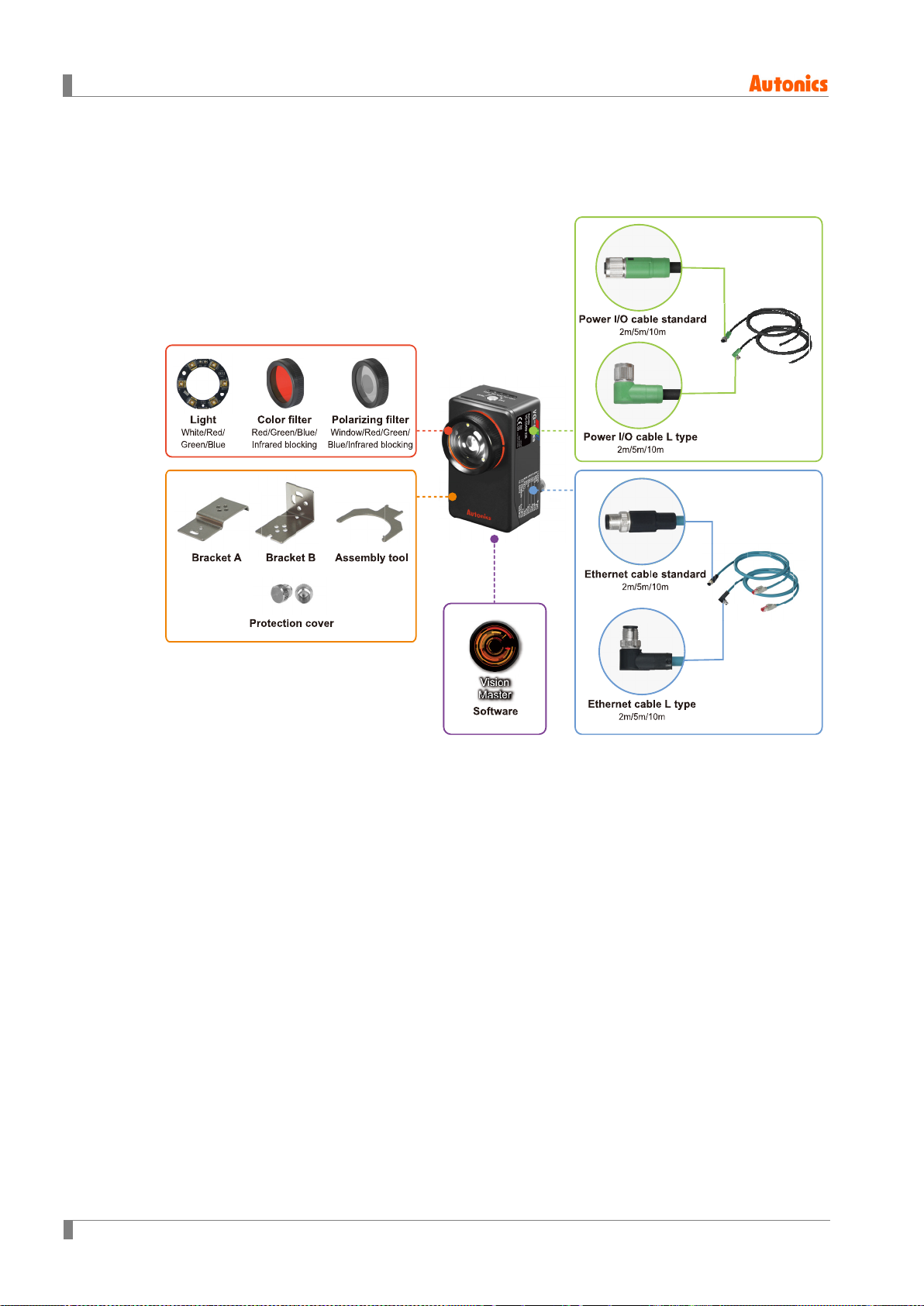
1.2 Accessory and sold separately
1.2.1 Overall configuration diagram
12 © Copyright Reserved Autonics Co., Ltd.
Page 13
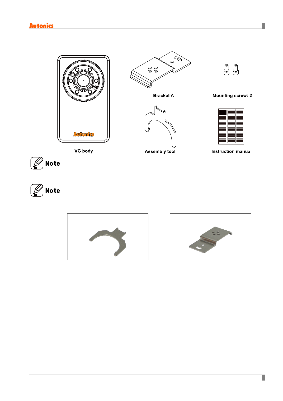
1.2.2 Accessory
Assembly tool
Bracket A
1 Product Instruction
Visit our homepage (www.autonics.com) to download vision sensor program (Vision Master).
Before using the product, please check whether all accessories above are included.
If there is a damaged or missing accessory, please contact Autonics sales team or retailer.
Please refer to the model name below, when purchasing the lost accessory.
■
ASST-VG
■
BK-VG-A
© Copyright Reserved Autonics Co., Ltd. 13
Page 14
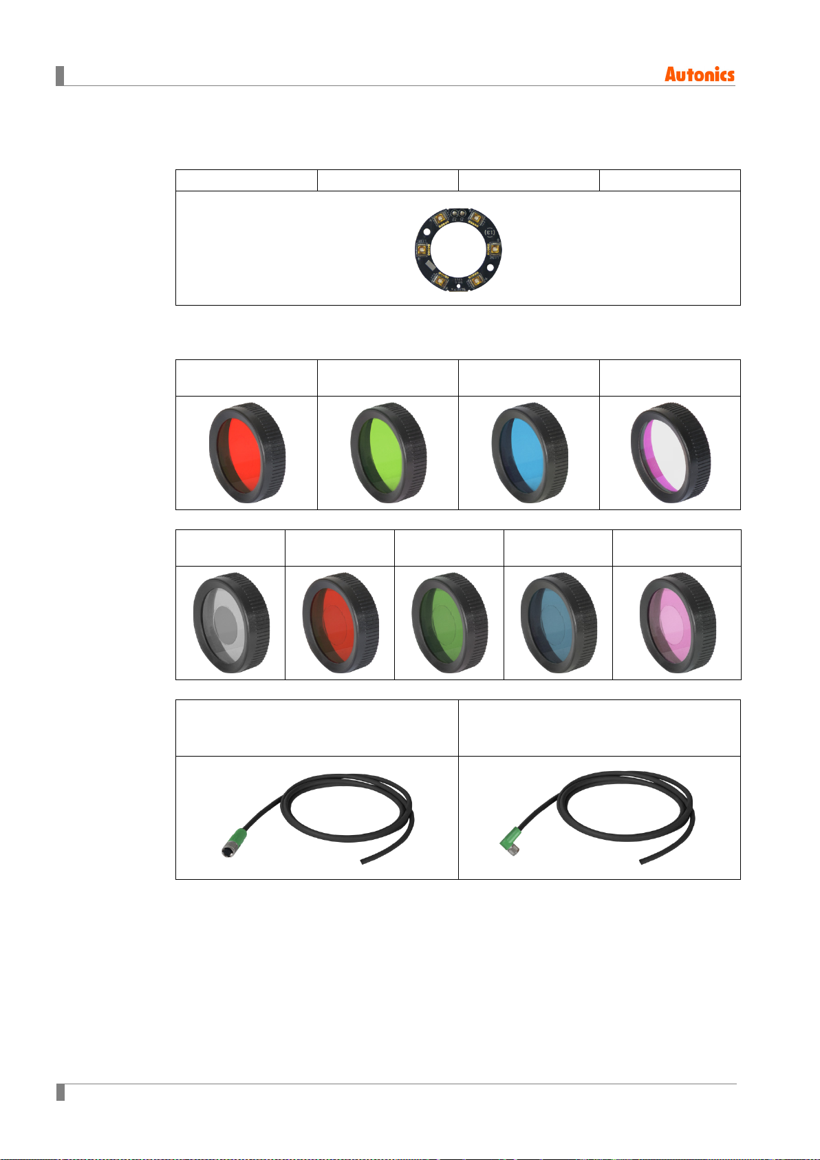
1 Product Instruction
1.2.3 Sold separately
Light
※
LR-W-06-VG (white)
LR-R-06-VG (red)
LR-G-06-VG (green) LR-B-06-VG (blue)
※Besides offered light, another type of lights are sold separately.
Color filter
FL-R-VG
(red)
FL-G-VG
(green)
FL-B-VG
(blue)
FL-IC-VG
(infrared blocking)
Polarizing filter
FL-P-VG
(window)
Power I/O cable
CID-2-VG (length: 2m)
CID-5-VG (length: 5m)
CID-10-VG (length:10m)
FL-RP-VG
(red)
FL-GP-VG
(green)
FL-BP-VG
(blue)
CLD-2-VG (length: 2m)
CLD-5-VG (length: 5m)
CLD-10-VG (length:10m)
FL-ICP-VG
(infrared blocking)
14 © Copyright Reserved Autonics Co., Ltd.
Page 15
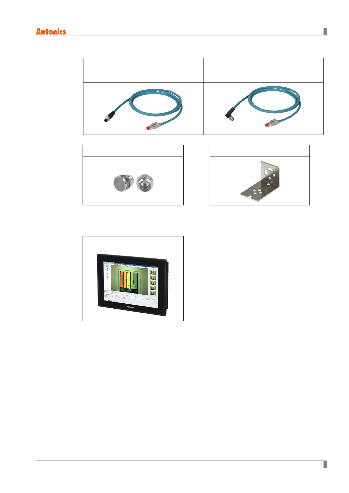
Ethernet cable
Vision panel
CIR-2-VG (length: 2m)
CIR-5-VG (length: 5m)
CIR-10-VG (length:10m)
1 Product Instruction
CLR-2-VG (length: 2m)
CLR-5-VG (length: 5m)
CLR-10-VG (length:10m)
■
Protection cover※
P96-M12-1
■
Bracket B
BK-VG-B
※Protection cover protects unused connectors from foreign substances.
When installing the protection cover, please tighten the cover with hand.
■
APC-1011
© Copyright Reserved Autonics Co., Ltd. 15
Page 16
1 Product Instruction
②
③
④
⑤
⑥
⑦
Items
Description
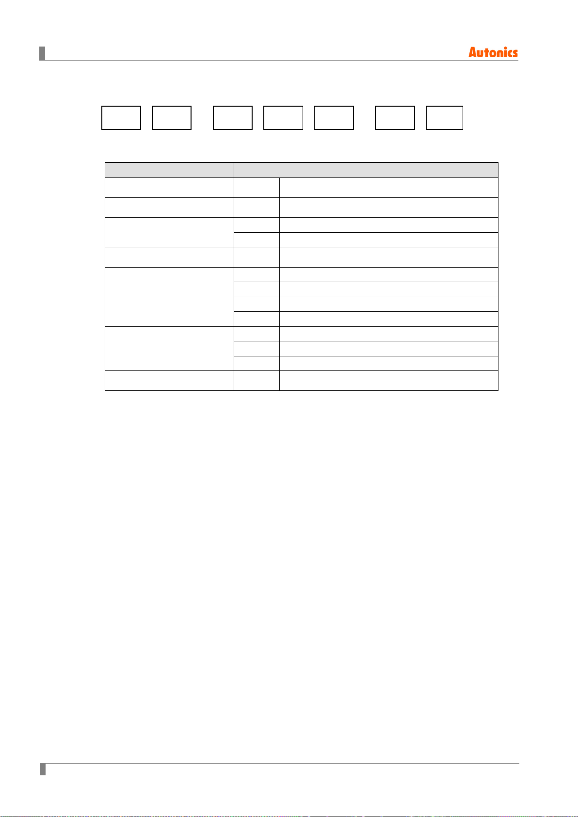
1.3 Ordering Information
V
①
① Item
② Type
③ Image element
④ Resolution (pixel)
⑤ Light
⑥ Effective focal length
⑦ Communication
※1.
Light can be purchased separately.
G - M 04 W - 8 E
V Vision sensor
G General inspection
M Mono CMOS
C Color CMOS
04
W White
R Red
G Green
B Blue
8 8mm
16 16mm
25 25mm
E Ethernet (TCP/IP)
752×480
16 © Copyright Reserved Autonics Co., Ltd.
Page 17
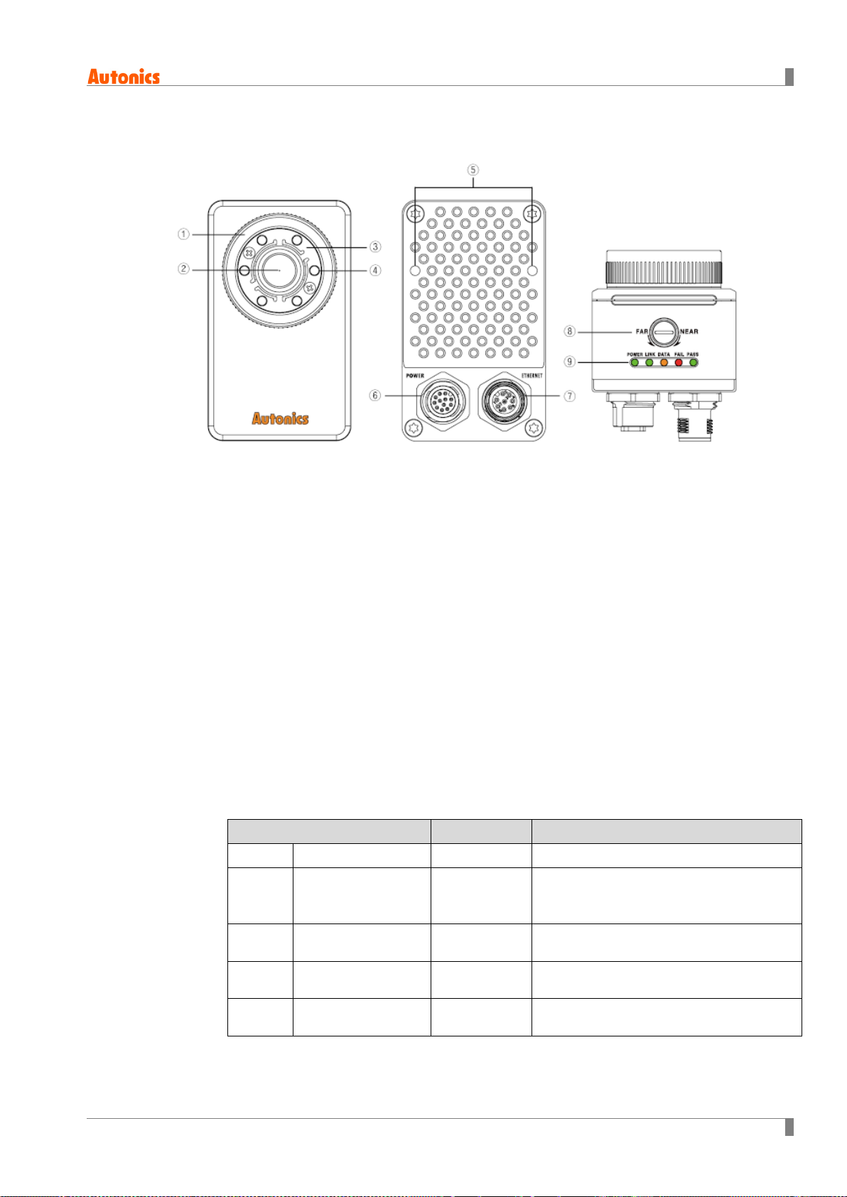
1.4 Unit Description
① Lens cover: Front cover of lens
※In case using a filter (color filter/polarizing filter), separate the lens cover with the
assembly tool before insert the filter.
1 Product Instruction
② Lens: There are 8mm, 16mm, 25mm models by effective focal length.
③ Light cover: Light cover fixes inner LED lights.
④ Light: Inner LED lights
※In order to change the light, separate lens cover and light cover.
⑤ Bracket mounting hole on back side:
Install the vision master from the back side using bracket B.
⑥ Power I/O connector: Connect the power I/O cable.
⑦ Ethernet connector: Connect the Ethernet cable. It is for TCP/IP communication.
⑧ Focus adjuster: After fixing vision sensor, adjust focus by rotating the focus adjuster.
⑨ Indicators
Indicator Color Descriptions
POWER Power indicator Green LED Turns ON when power is supplied.
LINK
DATA
FAIL Failure indicator Red LED
PASS Pass indicator Green LED
Ethernet connection
indicator
Data transmission
indicator
Green LED
Orange LED
Turns ON when vision sensor is
connected with PC
(Ethernet communication).
Flashes when data is transmitted from
vision sensor to PC.
Flashes when detects failure during work
group inspection.
Flashes when passed inspection during
work group inspection.
© Copyright Reserved Autonics Co., Ltd. 17
Page 18

1 Product Instruction
18 © Copyright Reserved Autonics Co., Ltd.
Page 19
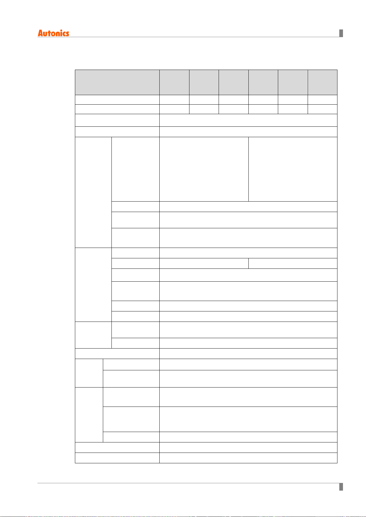
2 Specifications
VG-
8E
VG-
16E
VG-
25E
VG-
8E
VG-
16E
VG-C
25E
2 Specifications
Model
M04□-
M04□-
M04□-
C04□-
C04□-
C04□-
Effective focal length 8mm 16mm 25mm 8mm 16mm 25mm
Min. working distance 50mm 100mm 200mm 50mm 100mm 200mm
Power supply
24VDCᜡ (±10%)
Current consumption 1A
2
※
,
2
※
, edge, shape
※
2
,
Inspection
Inspection item
Alignment, brightness, contrast,
area, edge, shape comparison,
length, angle, diameter, object
counting
Alignment, brightness
2
contrast
comparison
※
, area
2
※
, length, angle,
diameter, object counting
color identification,
area of color, object of color
counting
Work group 32
Simultaneous
inspection
64
Camera frame
Max. 60fps
1
※
per second
Image filter Preprocessing, external filter (color filter, polarizing filter)
Image element 1/3 inch mono CMOS 1/3 inch color CMOS
Image
snap
Resolution
Camera frame
per second
※
752×480 pixel
Max. 60fps
1
Shutter Global shutter
Exposure time 20 to 10,000us
Light
ON/OFF
method
Pulse
Color White, red, green, blue
Trigger mode External trigger, internal trigger, free-run trigger
Rated input 24VDCᜡ (±10%)
External trigger (TRIG), work group change (IN0 to IN3),
alarm cleared (IN0 to IN3), encoder (IN2, IN3)
NPN or PNP open collector output
Max. 24VDCᜡ 50mA, residual voltage: max. 1.2VDCᜡ
Control output (OUT0 to OUT3)
: inspection completion, inspection result, external light trigger,
Input
Output
Signal
Type
Signal
Type
alarm, camera busy, changing work group completed
FTP transmission Possible
Communication Ethernet(TCP/IP), 100BASE-TX/10BASE-T
Protection circuit Output short over current protection circuit
© Copyright Reserved Autonics Co., Ltd. 19
Page 20
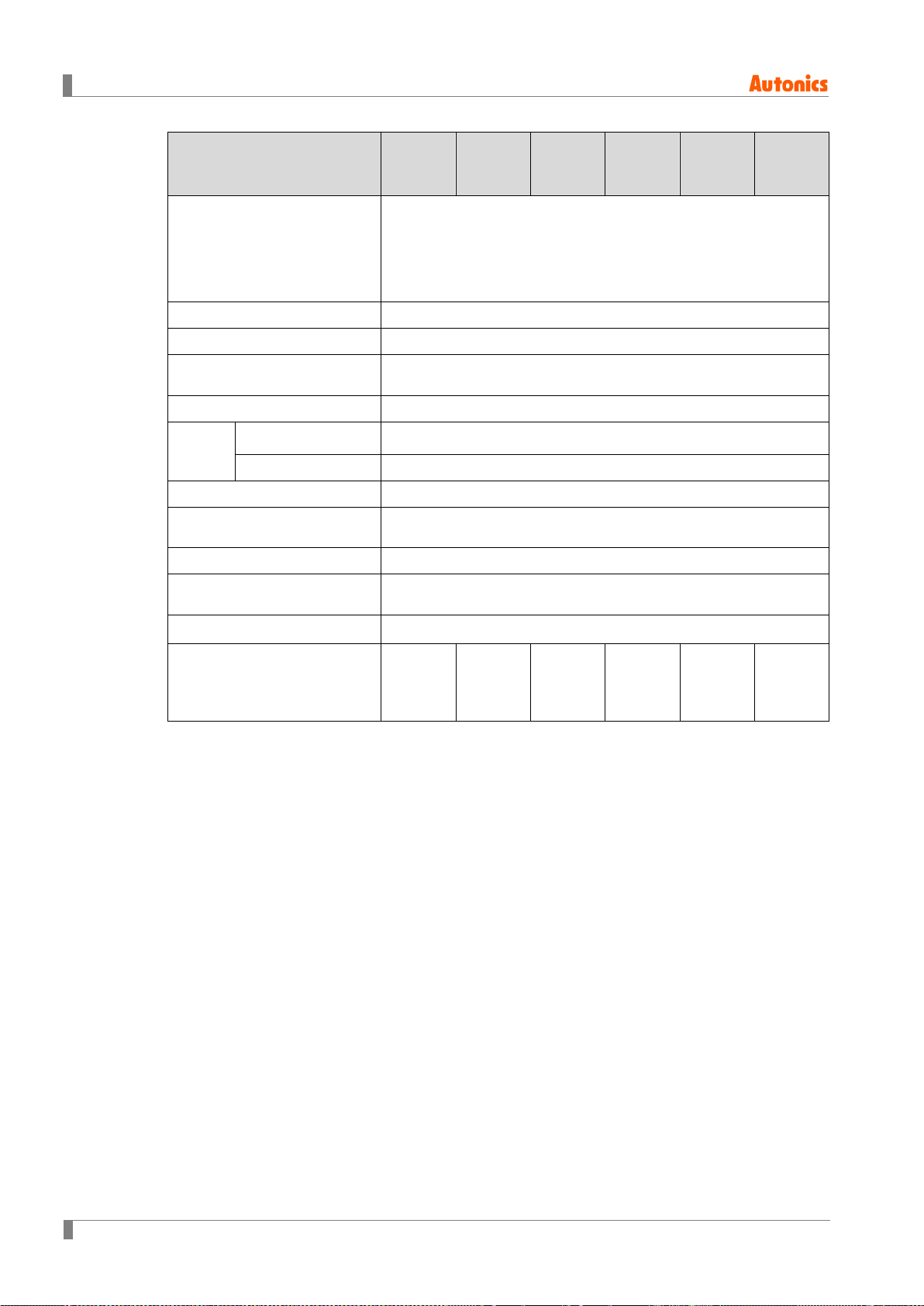
2 Specifications
VG-
8E
VG-
16E
VG-
25E
VG-
8E
VG-
16E
VG-C
25E
Model
Indicator
Insulation resistance Over 20MΩ (at 500VDC megger)
Dielectric strength 500VAC 50/60Hz for 1 min
Vibration
Shock 300m/s2 (approx. 30G) in each X, Y, Z direction for 3 times
Environ
ment
Protection structure IP67 (IEC standard)
Material
Accessories Assembly tool, bracket A, mounting screw: 2
Sold separately
Approval
Weight
Ambient temp.
3
※
Ambient humi. 35 to 85%RH, storage: 35 to 85%RH
4
※
M04□-
∙ Power indicator (POWER), Ethernet connection indicator
(LINK), pass indicator (PASS): green LED
∙ Data transmission indicator (DATA): orange LED
∙ Failure indicator (FAIL): red LED
1.5mm amplitude at frequency of 10 to 55Hz (for 1 min) in each X,
Y, Z direction for 2 hours
0 to 45℃, storage: -20 to 70℃
Case: aluminum, lens cover/focus adjuster: polycarbonate, cable:
polyurethane
Light, color filter, polarizing filter, power I/O cable, Ethernet cable,
bracket B, protection cover, vision panel
ᜢ, ᜣ
Approx.
415g
(approx.
273g)
M04□-
Approx.
416g
(approx.
274g)
M04□-
Approx.
416g
(approx.
274g)
C04□-
Approx.
415g
(approx.
273g)
C04□-
Approx.
416g
(approx.
274g)
C04□-
Approx.
416g
(approx.
274g)
※1. The number of camera frames per second can be different by image setting or inspection
item.
※2. These inspections identify data by converting the color image to the mono image.
※3. Environment resistance is rated at no freezing or condensation.
※4. The weight includes packaging. The weight in parenthesis is for unit only.
20 © Copyright Reserved Autonics Co., Ltd.
Page 21
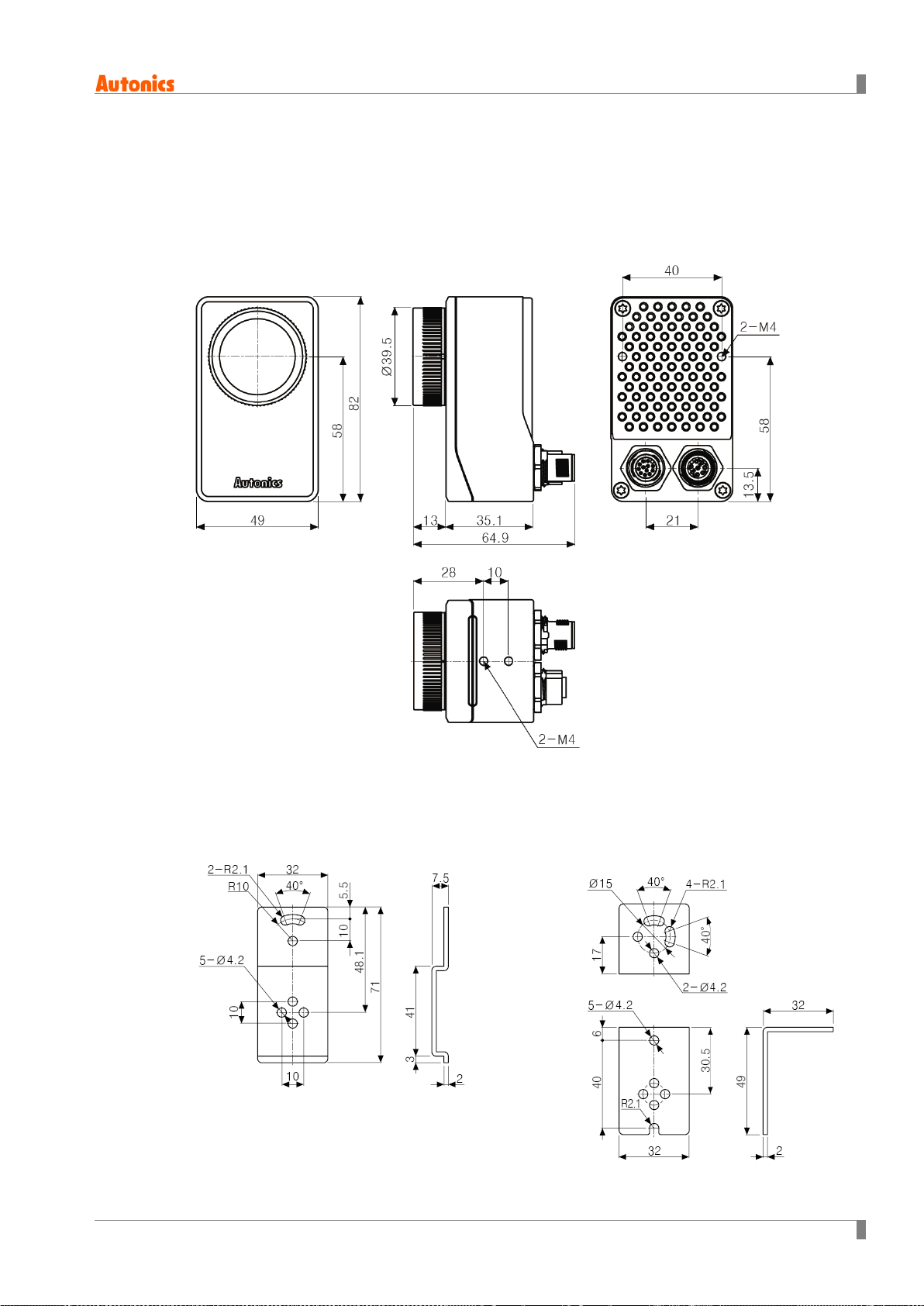
3 Dimensions
3.1 Body
3 Dimensions
(unit: mm)
3.2 Bracket
3.2.1 Bracket A (BK-VG-A)
3.2.2 Bracket B (BK-VG-B)
© Copyright Reserved Autonics Co., Ltd. 21
Page 22
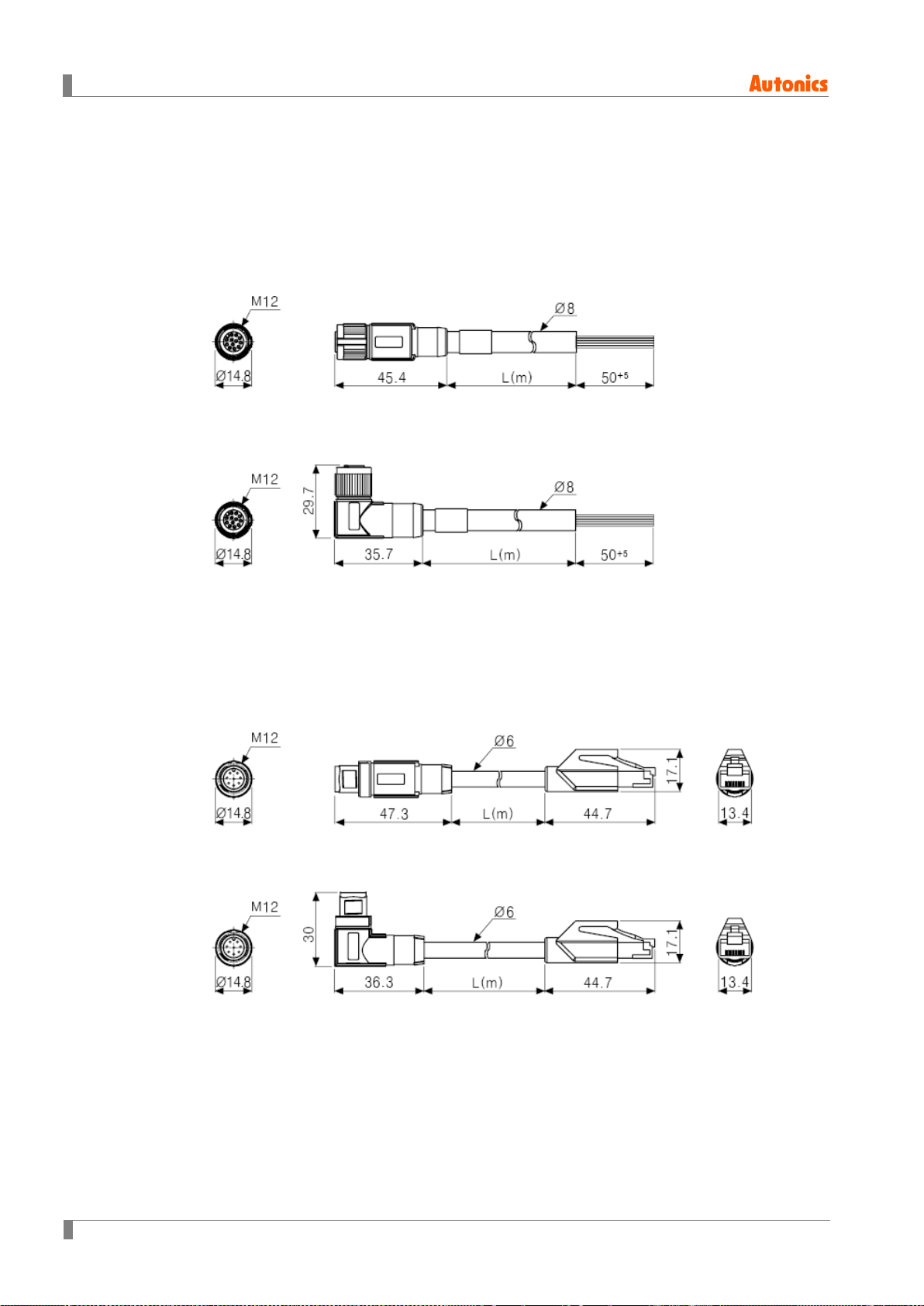
3 Dimensions
3.3 Cable
(unit: mm)
3.3.1 Power I/O cable
(1) CID Series
(2) CLD Series
※L(m): 2m, 5m, 10m
Please refer to the cable length.
3.3.2 Ethernet cable
(1) CIR Series
(2) CLR Series
※ L(m): 2m, 5m, 10m
Please refer to the cable length.
22 © Copyright Reserved Autonics Co., Ltd.
Page 23
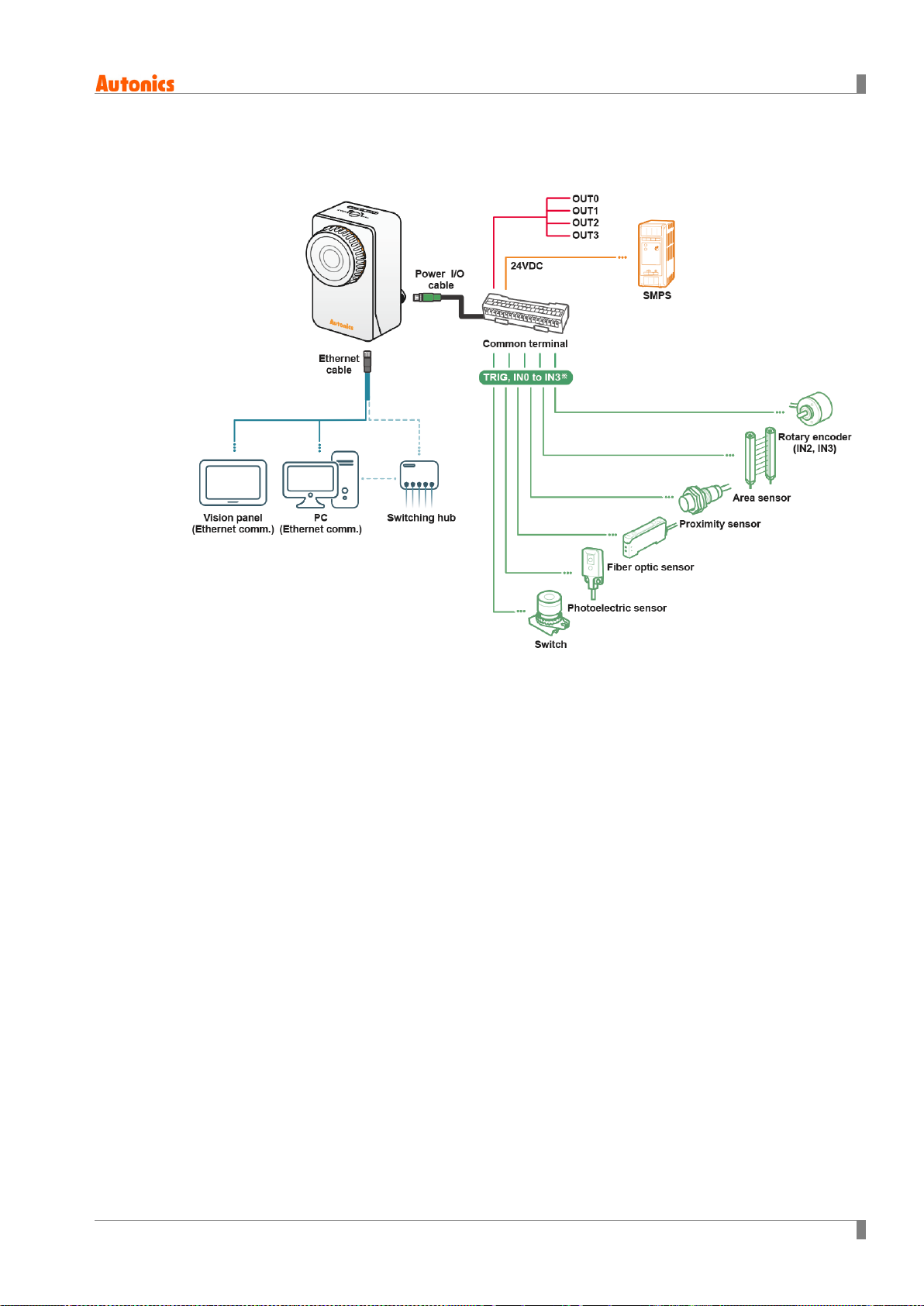
4 Connections
4 Connections
※ Use the product which of power supply is 24VDC.
When selecting a product, please refer to Autonics selection guide.
© Copyright Reserved Autonics Co., Ltd. 23
Page 24
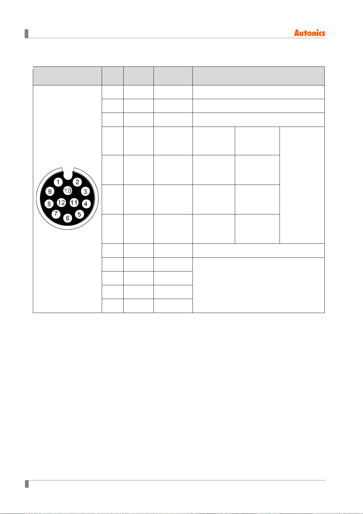
4 Connections
Pin
No.
Cable
color
4.1 Power I/O Cable (M12 12-pin connector)
Pin arrangement
Signal Function
1
2
3
4
5
6
8
11
Brown 24VDC 24VDC
Blue GND GND
White TRIG Trigger input
Green IN0
Pink IN1
Yellow IN2
Gray IN3
Gray/Pink
COMMON COMMON
Work group
change Bit 0
Work group
change Bit 1
Work group
change Bit 2
Work group
change Bit 3
Work group
change
- Clock
Work group
change
- Data
Alarm cleared
Encoder
- Up counter
- Quadrature A
Encoder
- Down counter
- Quadrature B
7
9
10
12
Black OUT0
Red OUT1
Purple OUT2
Red/Blue OUT3
Inspection completion, inspection result,
external light trigger, alarm, camera busy,
changing work group completed
24 © Copyright Reserved Autonics Co., Ltd.
Page 25
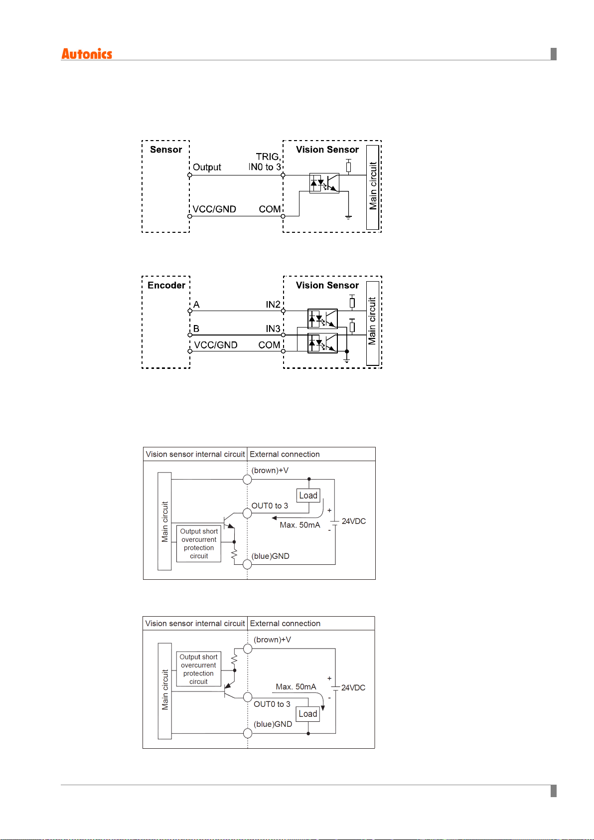
4.1.1 Input
(1) External trigger input (TRIG), Work group change input (IN0 to IN3)
Alarm cleared (IN0 to IN3)
(2) Encoder input (IN2, IN3)
4 Connections
4.1.2 Output (OUT0 to OUT3)
(1) NPN open collector output
(2) PNP open collector output
© Copyright Reserved Autonics Co., Ltd. 25
Page 26
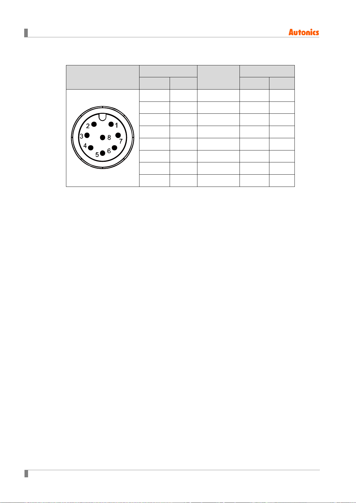
4 Connections
4.2 Ethernet Cable (M12 8-pin/RJ45 connector)
Pin arrangement
M12 8-pin
RJ45
Cable color
Pin No. Signal Pin No. Signal
6 RX+ White/Orange 1 TX+
4 RX- Orange 2 TX-
5 TX+ White/Green 3 RX+
8 TX- Green 6 RX-
1 - White/Blue 5 -
7 - Blue 4 -
2 - White/Brown 7 -
3 - Brown 8 -
26 © Copyright Reserved Autonics Co., Ltd.
Page 27
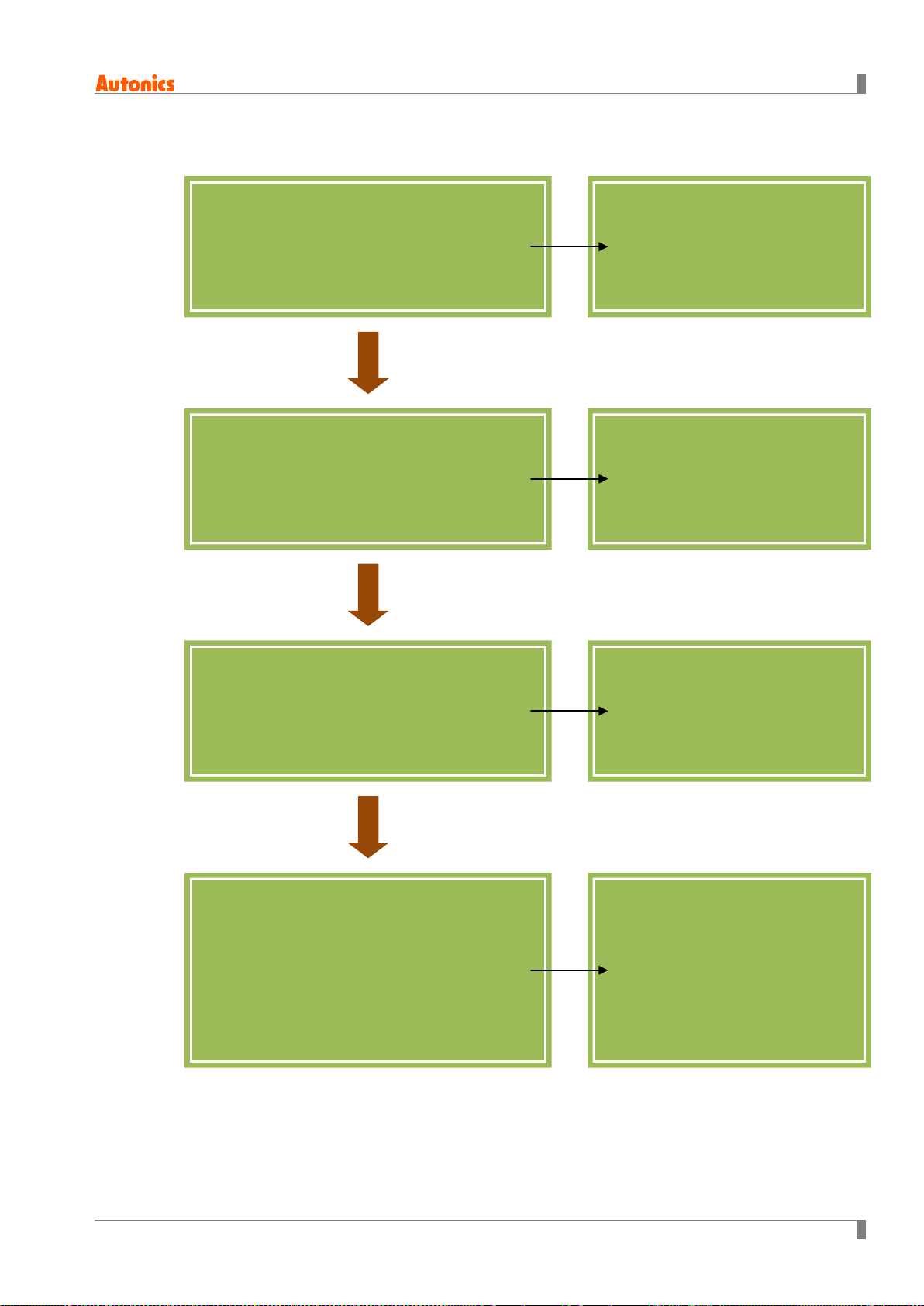
5 Installation
- Installing bracket (fixing vision sensor)
5 Installation
Installing vision sensor
- Checking working distance and FOV by
effective focal length
Installing software
- Installing the vision sensor program, Vision
Master, to PC
5.1 Working Distance and FOV
by Effective Focal Length
5.2 Installation of Vision Sensor
6.3.1 System requirements
6.3.2 Installation of the program
Connecting vision sensor and PC
- Setting network from Vision Master
Adjusting vision sensor focus
- Running Vision Master and activating the
'Focusing Guide' function in the camera
setting menu
- Adjusting focus with focus adjuster
6.3.5 Network setting
6.6.2 Camera
5.3 Focus Adjustment
© Copyright Reserved Autonics Co., Ltd. 27
Page 28
5 Installation
Effective
length
Horizontal
axis (H)
Vertical
axis (V)
Horizontal
axis (H)
Vertical
axis (V)
Horizontal
axis (H)
Vertical
axis (V)
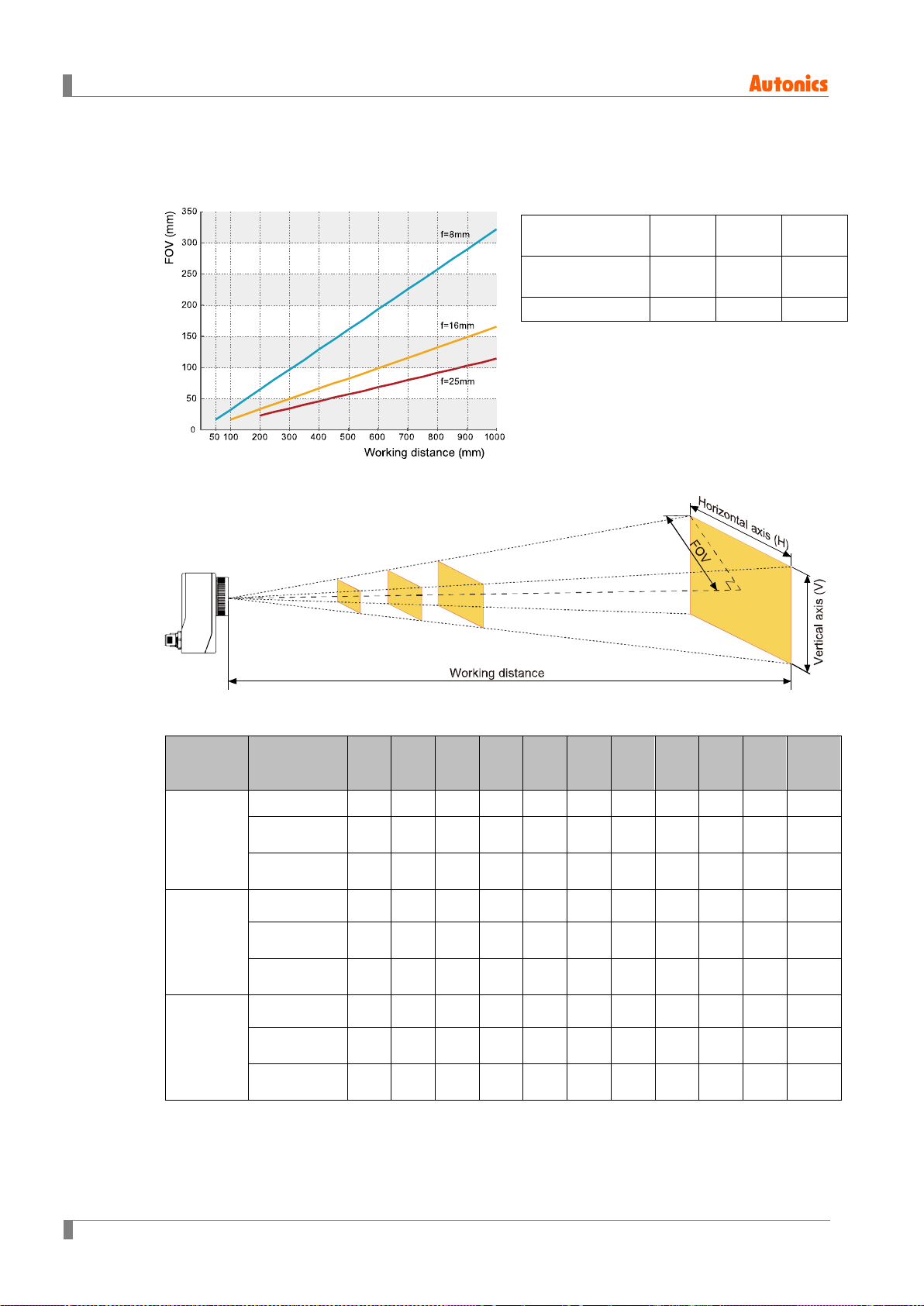
5.1 Working Distance and FOV by Effective Focal Length
Please check working distance by effective focal length and FOV (Field of View).
Effective focal
length(f)
Min. working
distance
Brightness F2.0 F2.5 F2.5
8mm 16mm 25mm
50mm 100mm 200mm
※Sensing range by effective focal length (unit: mm)
focal
8mm
16mm
25mm
Working
distance
FOV
FOV
FOV
50 100 200 300 400 500 600 700 800 900 1,000
16 32 64 96 129 161 193 255 257 289 322
27 54 108 163 217 271 325 380 434 488 542
17 35 69 104 138 173 208 242 277 311 346
16 33 49 66 82 99 155 132 148 165
ㅡ
28 56 83 111 139 167 195 222 250 278
ㅡ
18 35 53 71 89 106 124 142 160 177
ㅡ
ㅡ ㅡ
ㅡ ㅡ
ㅡ ㅡ
23 34 46 57 68 80 91 103 114
38 58 77 96 115 134 154 173 192
25 37 49 61 74 86 98 110 123
28 © Copyright Reserved Autonics Co., Ltd.
Page 29
5.2 Installation of Vision Sensor
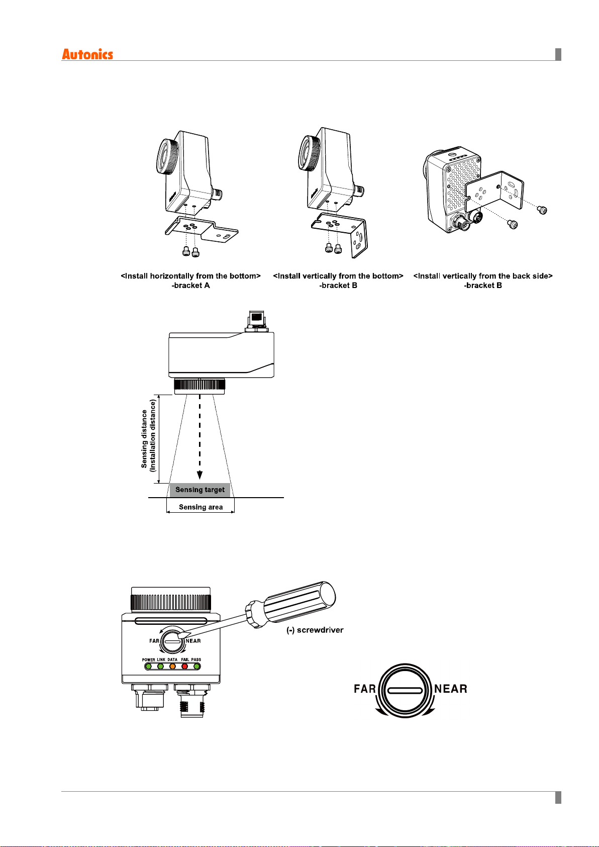
1st Fix vision sensor using bracket.
2nd Place the sensing target at the center of the vision sensor lens.
5 Installation
5.3 Focus Adjustment
After installing and running Vision Master, use the focusing guide function to adjust the focus.
Using (-) screwdriver, turn focus adjuster to right and left to adjust the focus.
※Please refer to '6.3 Installation of Vision Master' for the installation of Vision Master and
network setting.
※Please refer to '6.6.2 Camera (6) Focusing guide ' for the focusing guide.
© Copyright Reserved Autonics Co., Ltd. 29
Page 30
5 Installation
5.4 Replacement of Light and Filter
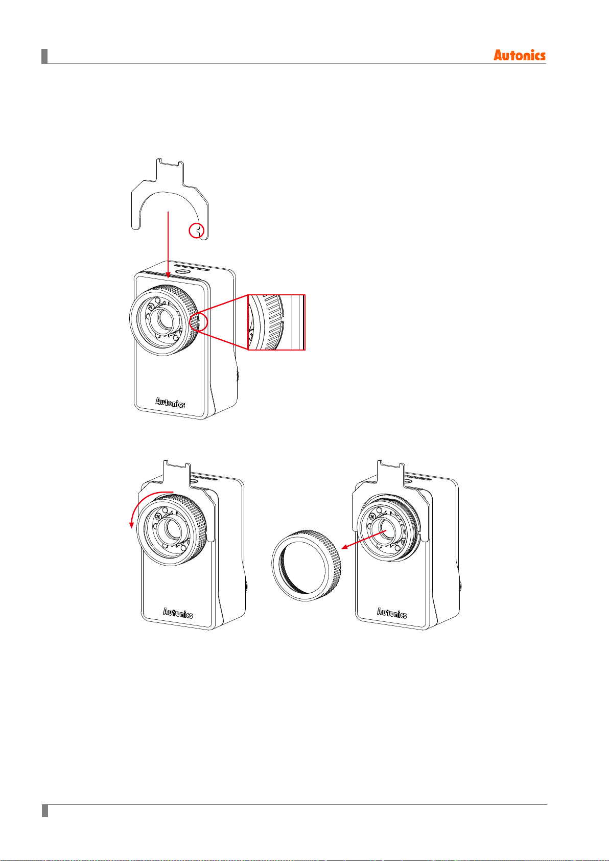
5.4.1 Replacement of color filter or polarizing filter
1st Put and fix the assembly tool into the groove on the side of the vision sensor.
2nd While fixing the vision sensor with the assembly tool, hold the lens cover and disassemble it
in a counter clock wise direction.
3rd Instead of the disassembled lens cover, assemble another color filter or polarizing filter in
clock wise direction.
30 © Copyright Reserved Autonics Co., Ltd.
Page 31
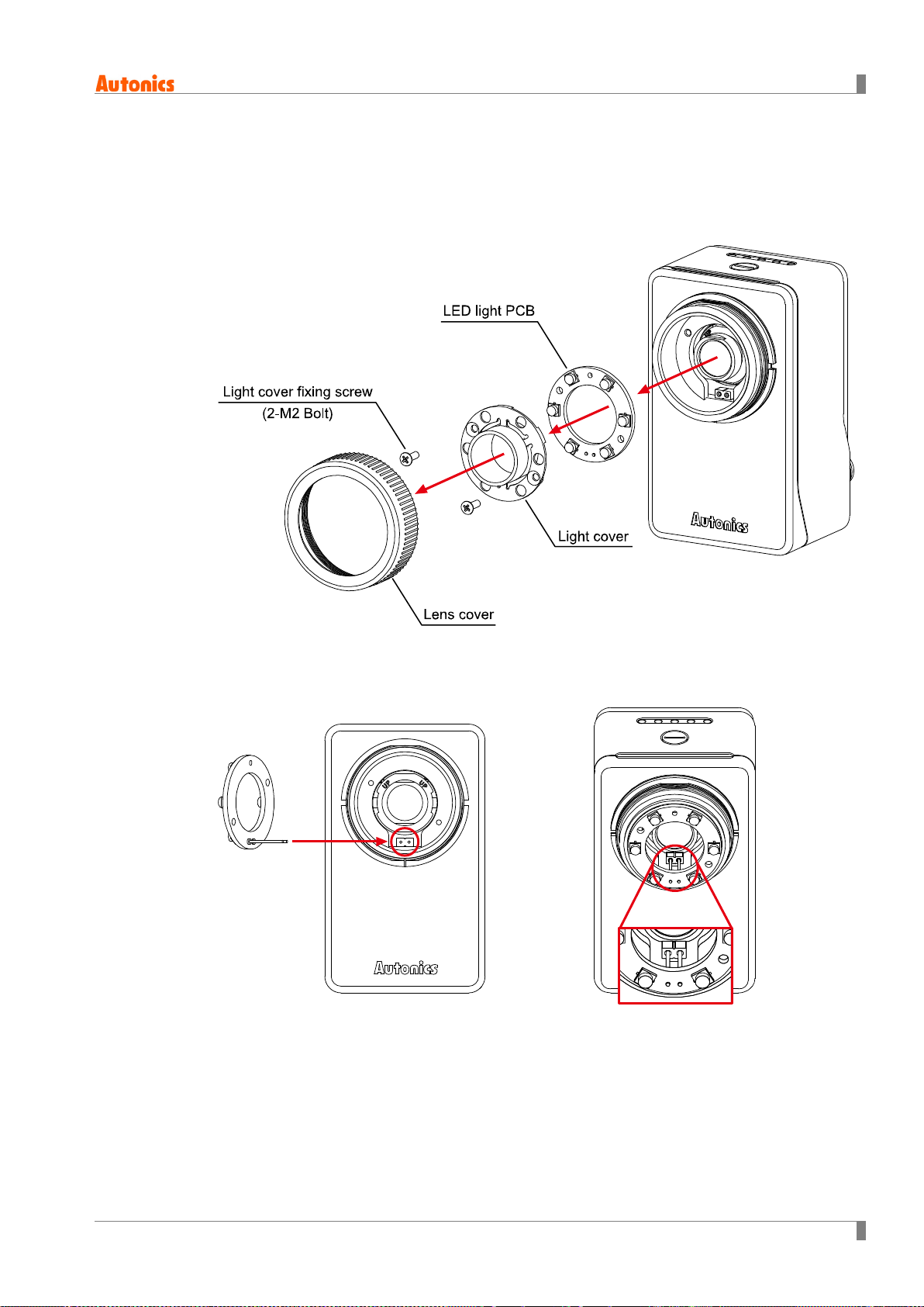
5.4.2 Replacement of light
1st Put and fix the assembly tool into the groove on the side of the vision sensor.
2nd While fixing the vision sensor with the assembly tool, hold the lens cover and disassemble it
in a counter clock wise direction.
3rd Disassemble the light cover using the (+) screwdriver, and disassemble the inner LED light.
5 Installation
4th Place the connection pin of PCB of the inner LED light to face the direction of 6 o’clock and
assemble it to the vision sensor body.
© Copyright Reserved Autonics Co., Ltd. 31
Page 32
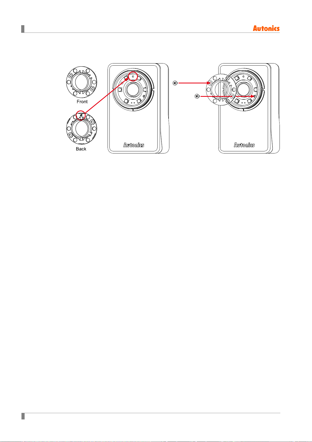
5 Installation
5th Align the light cover with the groove in the direction of 12o’clock and fix it with the screw.
Tighten them with the 1.2kgf∙cm of tightening torque.
6th Assemble the disassembled lens cover in clock wise direction.
32 © Copyright Reserved Autonics Co., Ltd.
Page 33
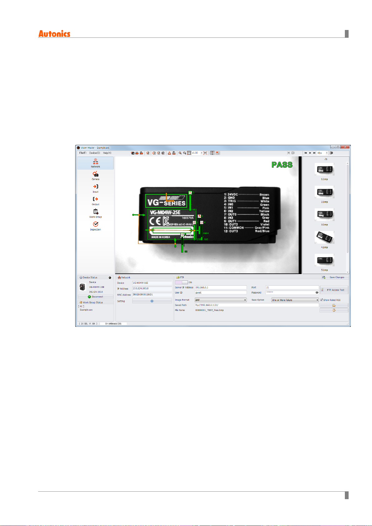
6 Vision Sensor Program [Vision Master]
6 Vision Sensor Program [Vision Master]
6.1 Overview
Vision Master is the vision sensor program that is connected with VG Series, Autonics vision
sensor, to utilize it.
Vision Master provides graphic user interface to make setting parameter and managing
monitoring data of vision sensor easy.
It is connected with vision sensor through Ethernet (TCP/IP) and exchange data with vision
sensor.
© Copyright Reserved Autonics Co., Ltd. 33
Page 34
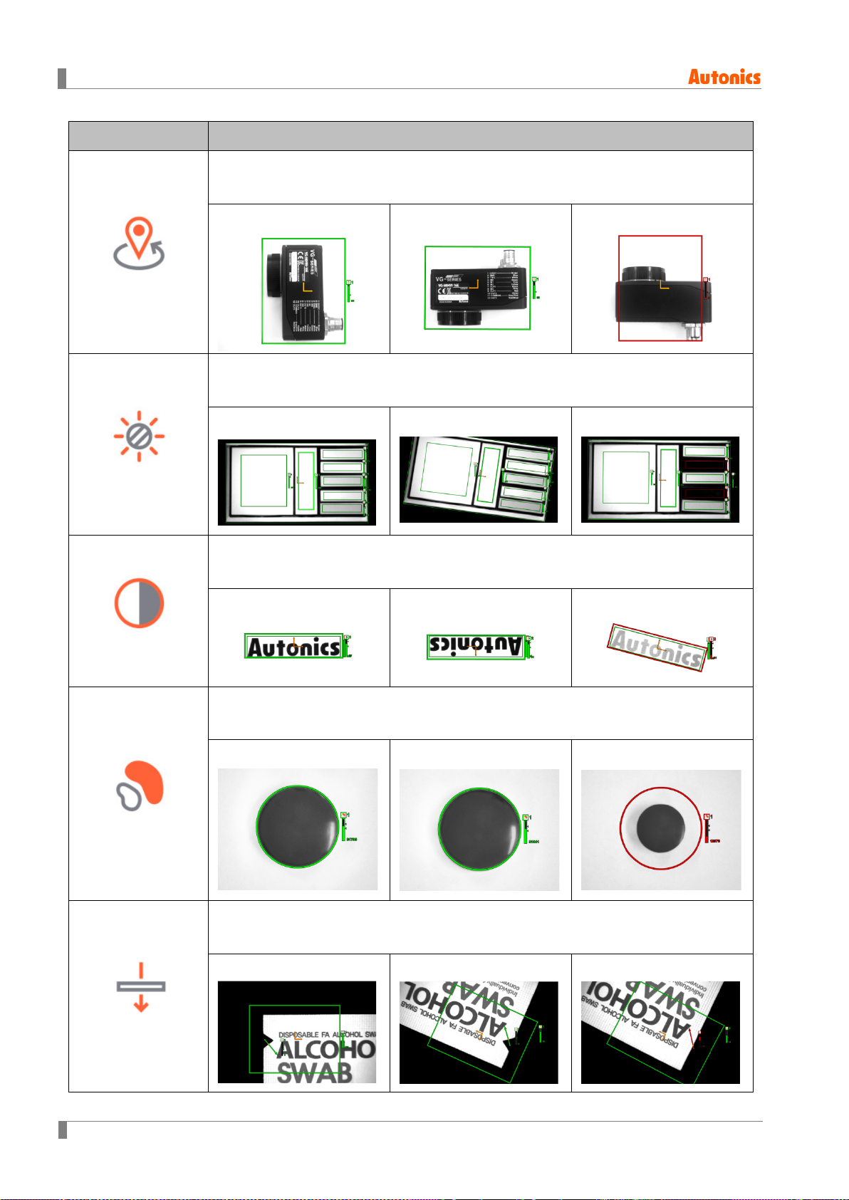
6 Vision Sensor Program [Vision Master]
Item Description
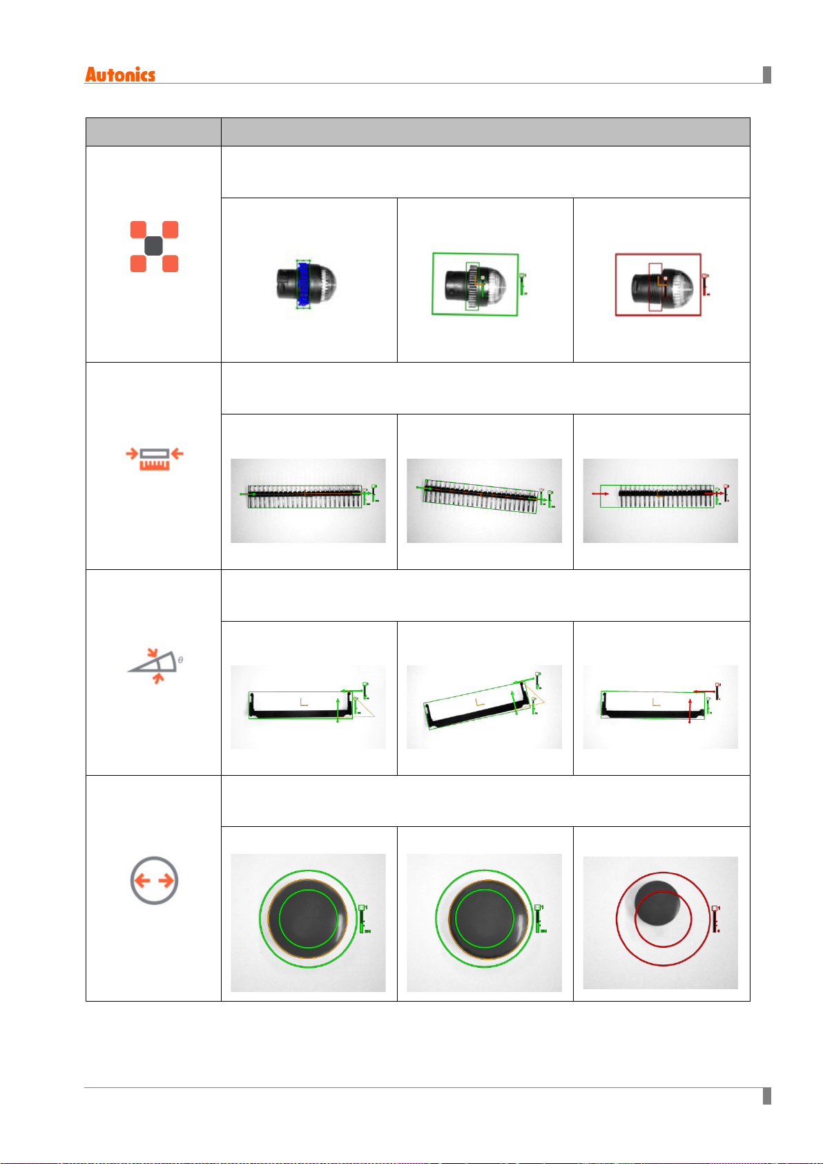
Compares features of the registered image and input image to search for a similar
pattern position, and inspects the input image with information of the searched pattern
position and rotation angle.
Alignment
Brightness
Contrast
<Template>
<Pass>
<Fail>
Inspects brightness of the ROI in the input image based on the mean brightness value of
the ROI (Region of Interest) in the registered image.
<Template>
<Pass>
<Fail>
Inspects contrast of the ROI in the input image based on contrast of the ROI in the
registered image.
<Template>
<Pass>
<Fail>
Area
.
Edge
Inspects the ROI area of the input image based on the ROI area of the image registered
by user.
<Template>
<Pass>
<Fail>
Inspects the direction of the edge in the input image based on the edge registered by
user in the same area.
<Template>
<Pass>
<Fail>
34 © Copyright Reserved Autonics Co., Ltd.
Page 35
Item Description
Compares shape of object in the ROI registered by user and that of the input image.
6 Vision Sensor Program [Vision Master]
Shape comparison
Length
<Template>
Inspects the input image based on the length between two edges registered by user.
<Template>
Inspects the input image based on the angle between two edges registered by user.
<Pass>
<Pass>
<Fail>
<Fail>
Angle
Diameter
<Template>
<Pass>
<Fail>
Inspects the input image based on the area between two circles registered by user.
<Template>
<Pass>
<Fail>
© Copyright Reserved Autonics Co., Ltd. 35
Page 36
6 Vision Sensor Program [Vision Master]
Item Description
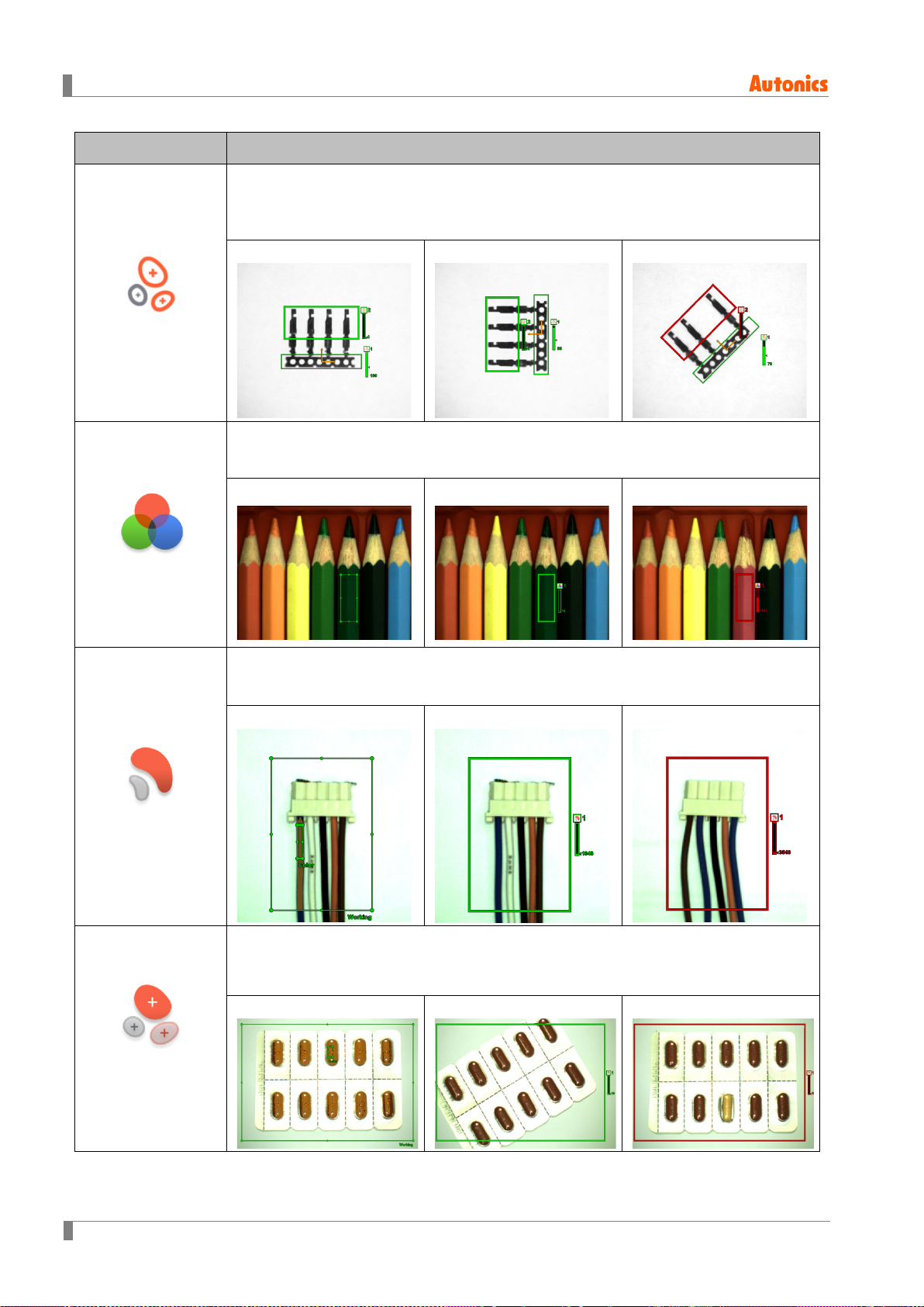
Compares the number of objects in the ROI which is in the image registered by user and
that in the input image.
Object counting
Color identification
<Template>
Compares color of the ROI registered by user and that of the input image.
<Template>
Compares the area of a certain color in the ROI registered by user and that in the input
image.
<Pass>
<Pass>
<Fail>
<Fail>
Area of color
Object of color
counting
<Template>
Compares the number of objects in a certain color which are in the ROI of registered
image and that of the input image.
<Template>
<Pass>
<Pass>
<Fail>
<Fail>
※Color identification, area of color, and object of color counting are only for VG-C Series.
36 © Copyright Reserved Autonics Co., Ltd.
Page 37
6.2 Vision Master Work Flow
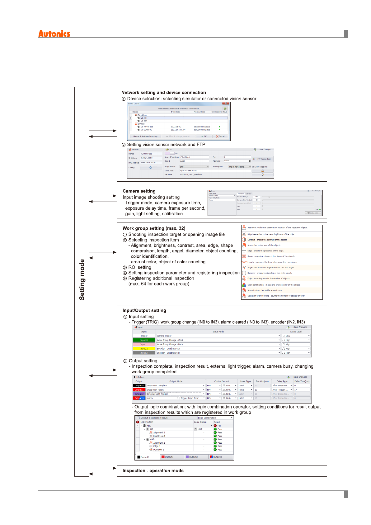
6.2.1 Setting mode
6 Vision Sensor Program [Vision Master]
© Copyright Reserved Autonics Co., Ltd. 37
Page 38
6 Vision Sensor Program [Vision Master]
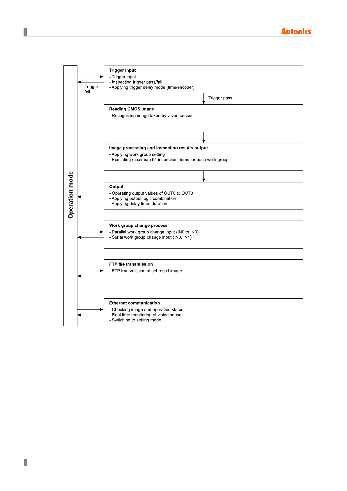
6.2.2 Operation mode
38 © Copyright Reserved Autonics Co., Ltd.
Page 39
6.3 Installation of Vision Master
6.3.1 System requirements
Item Minimum specifications
System 32bit (×86) or 64bit (×64) processor over 1GHz
Operations Microsoft Windows 7/8/10
Memory 1GB+
Hard disk 400MB+ of available hard disk space
VGA Resolution: 1024×768 or higher
Others RJ45 Ethernet port
6.3.2 Installation of the program
1st Download Vision Master program at Autonics web page(www.autonics.com).
2nd Close all programs before you start Vision Master installation.
Double-click Vision Master setup.exe to start installation.
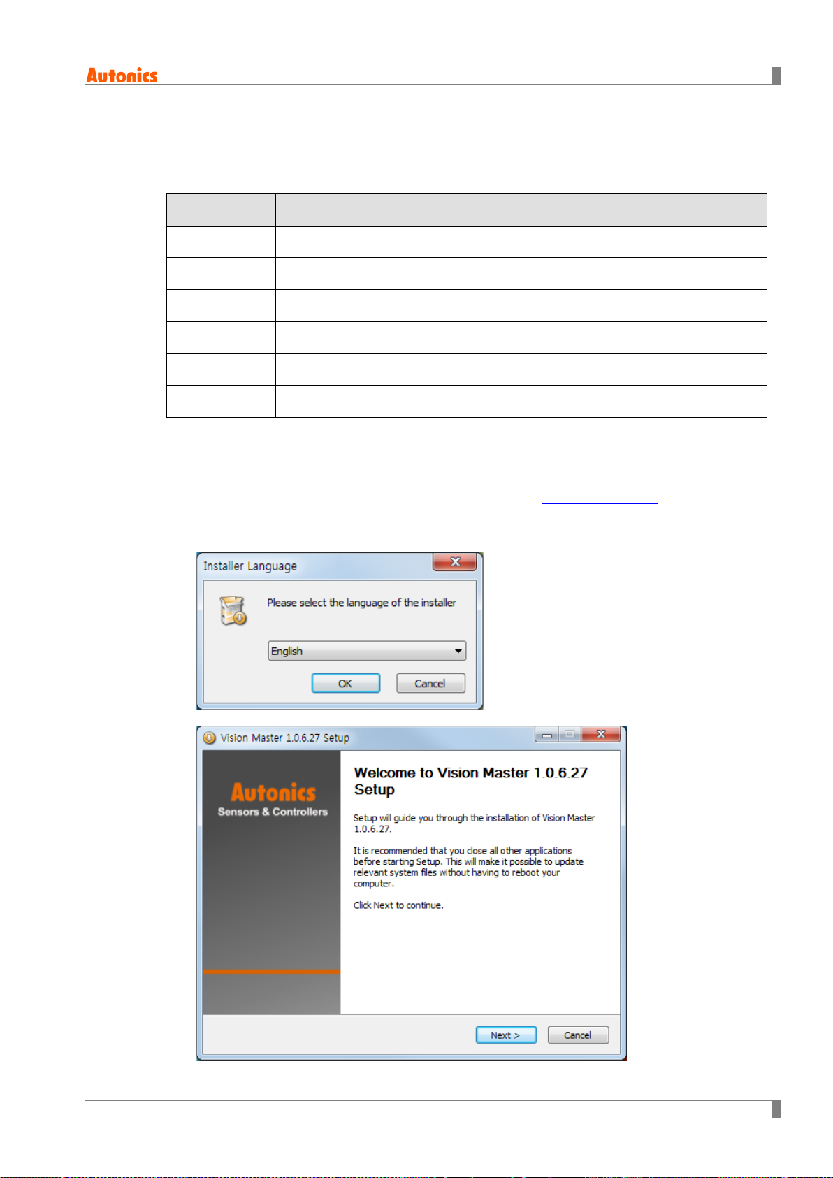
3rd When Installer Language window appears, select the language and click [OK] button.
6 Vision Sensor Program [Vision Master]
4th Click [Next] button in the installation welcome window.
© Copyright Reserved Autonics Co., Ltd. 39
Page 40
6 Vision Sensor Program [Vision Master]
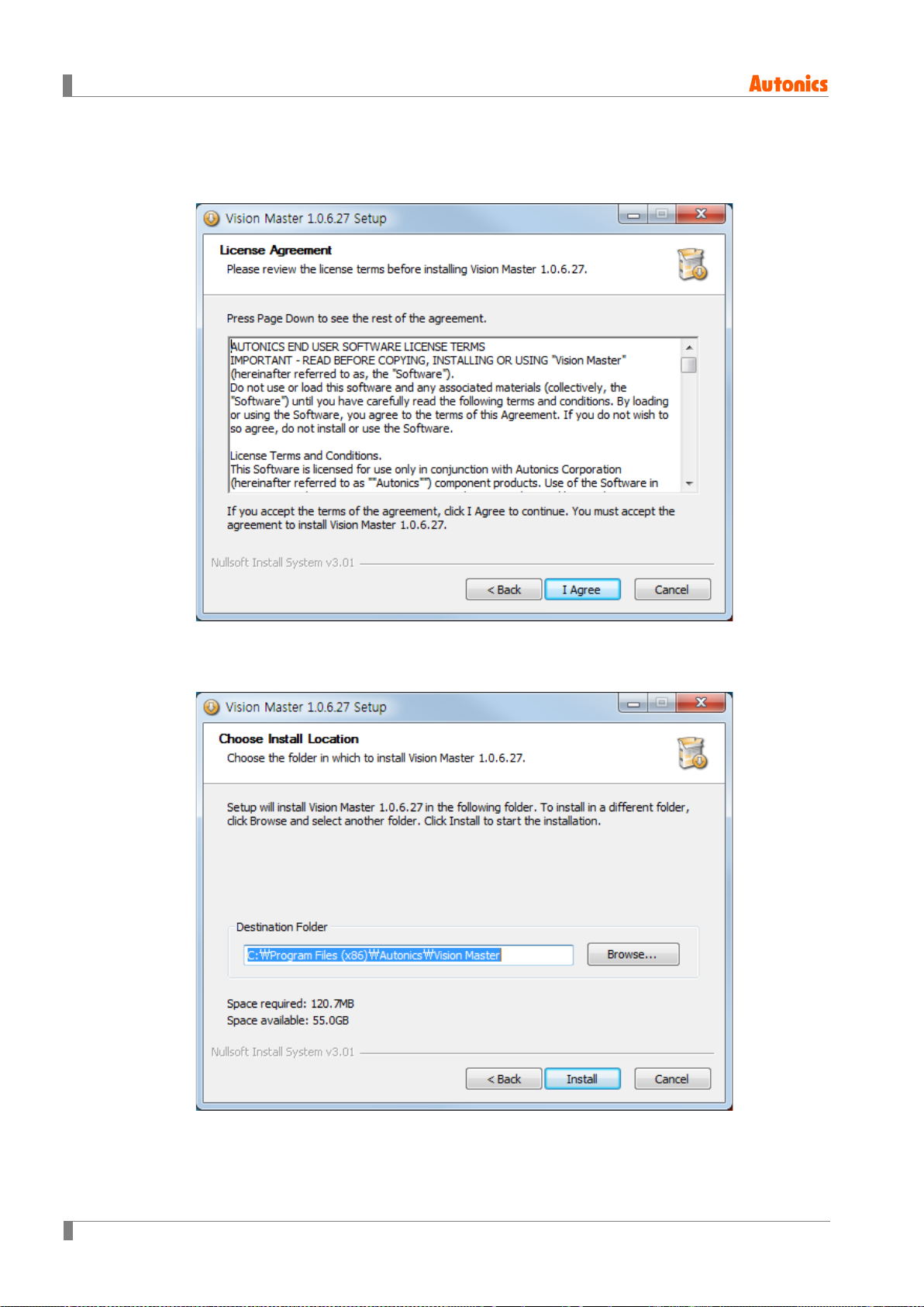
5th This process is license agreement.
You can check whole part of license agreement article by rolling mouse scroll downward,
clicking downward arrow or press “Page Down(PgDn)” Key of the keyboard.
Please read the articles thoroughly before click [I Agree] button.
6th Choose Install Location window appears.
Default installation path is as follows.
C:\Program Files (x86)\Autonics\Vision Master\
Click [OK] button to install the program in the default installation path.
40 © Copyright Reserved Autonics Co., Ltd.
Page 41
6 Vision Sensor Program [Vision Master]
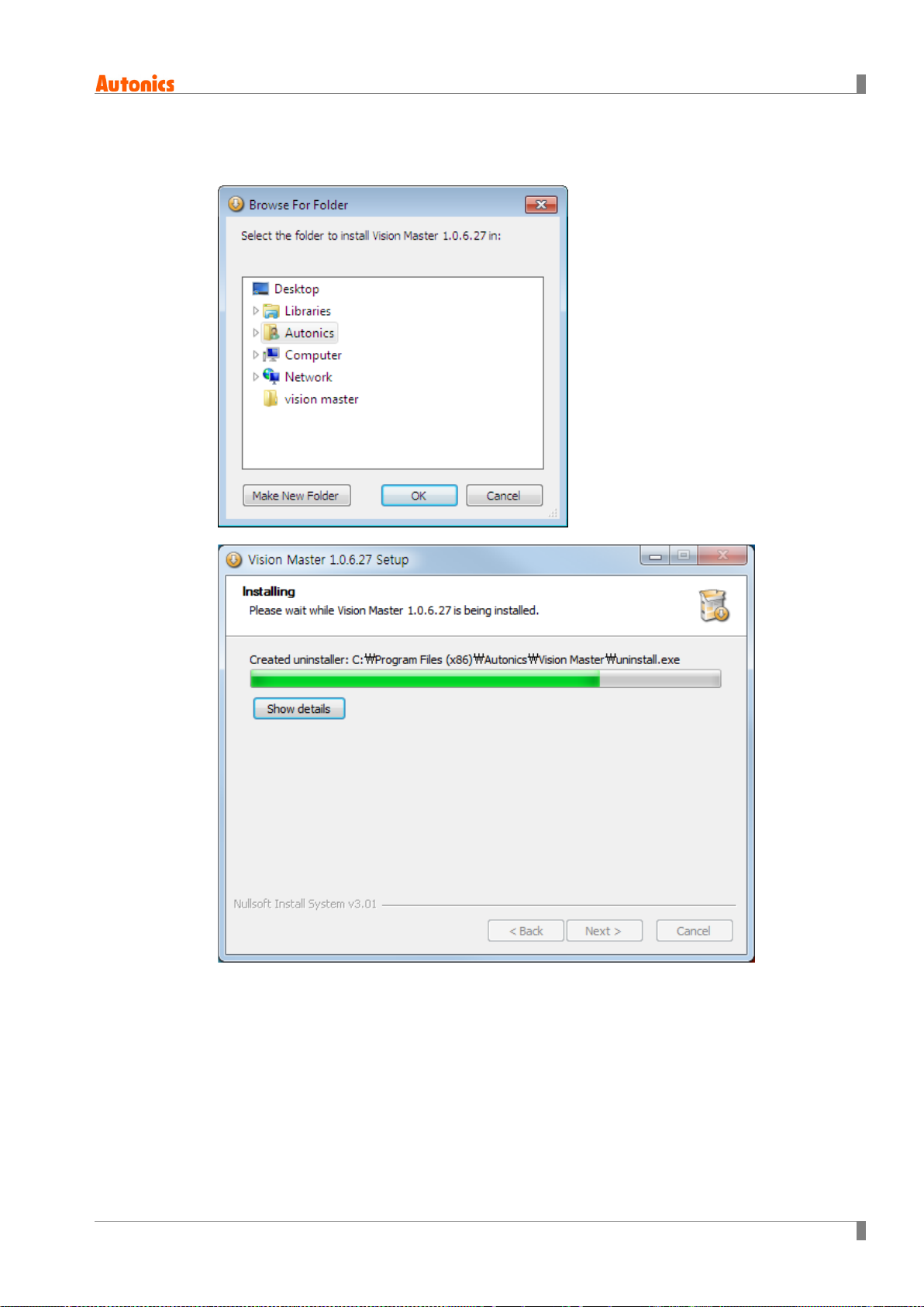
7th Click [Install] button to install the program in the default installation path.
If you want to install the program in another installation path, click [Browse..] button to
designate a folder you want to install in and click [OK] button.
8th Installation progress is displayed in the status window as follows.
© Copyright Reserved Autonics Co., Ltd. 41
Page 42
6 Vision Sensor Program [Vision Master]
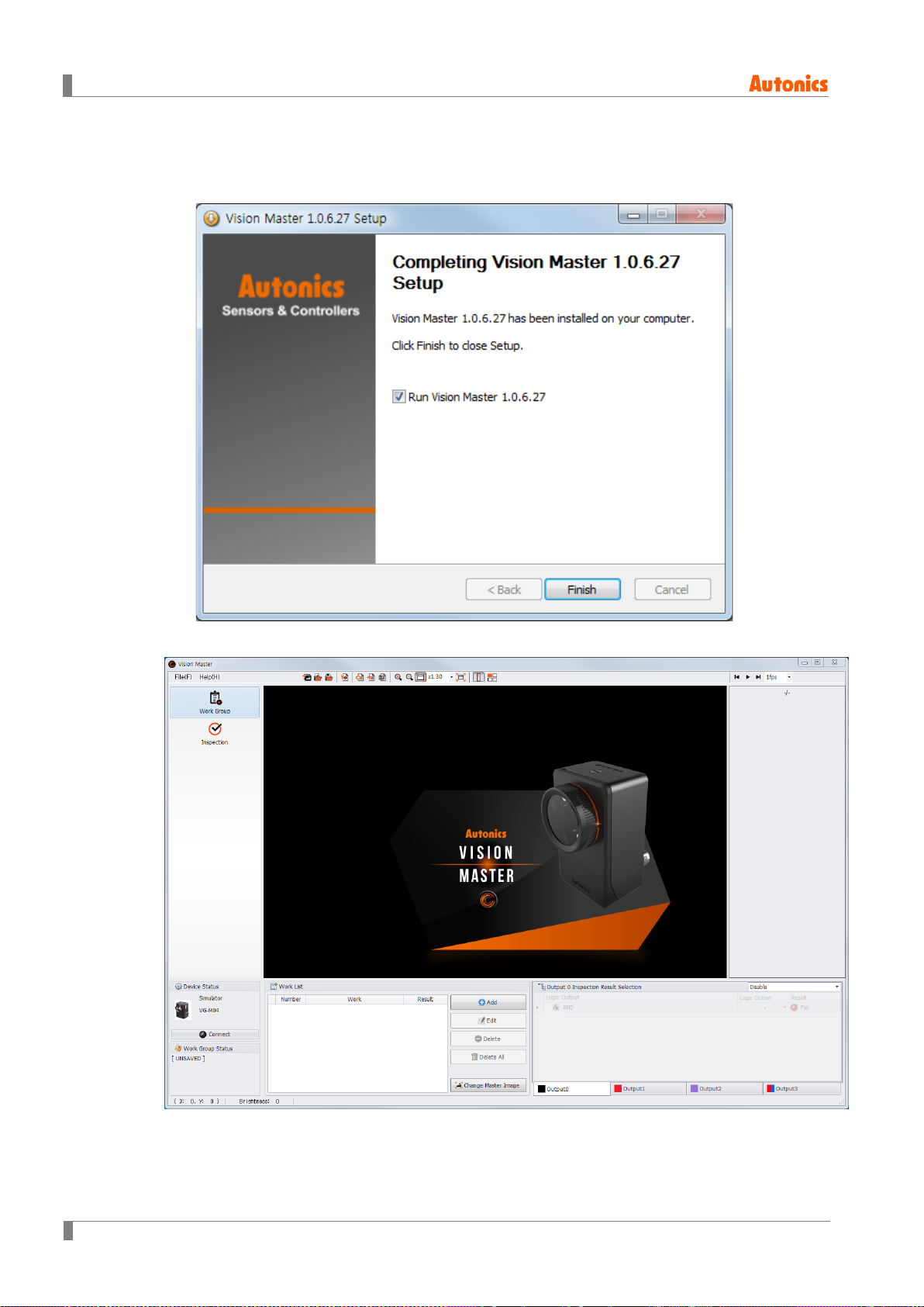
9th Installation Complete window appears after installation is completed.
If the check box in the Installation Complete window is checked, Vision Master runs upon
completion of installation.
You can run Vision Master by double-clicking the Vision Master icon on the desktop.
The initial screen displays as follows.
42 © Copyright Reserved Autonics Co., Ltd.
Page 43
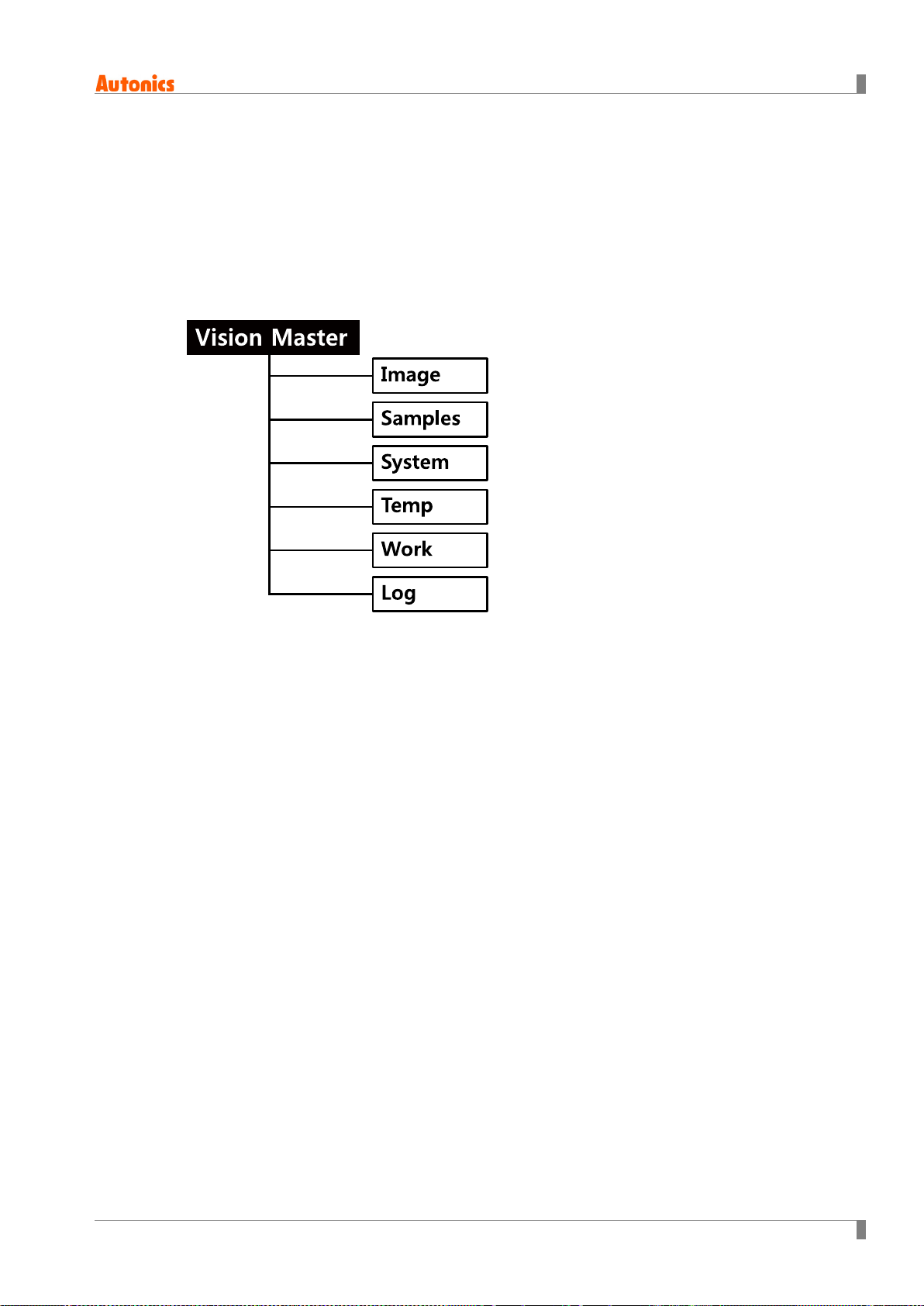
6.3.3 Installation folder structure
This section explains the folder structure created when you installed Vision Master.
The Vision Master folder is created in [C:\Program Files (x86)\Autonics\] as a subfolder unless
you select a new destination to change location of Vision Master folder.
After Vision Master is installed completely, Vision Master installation folder and related folders
are created as follows in [C:\Users\(Account name)\Documents\Autonics\] as subfolders and
work groups and documents are saved in. The program and all relevant documents are stored in
these folders.
6 Vision Sensor Program [Vision Master]
(1) Image folder
If Save Result Image inspection parameter of Vision Master is set to ON, inspection result
images are saved in the designated location. Saving location is fixed, so that is cannot be
changed by user.
Inspection result images are saved in [C:\Users\(Account name)\Documents\Autonics\Vision
Master\Image\ResultImage].
(2) Sample folder
This folder contains work groups for samples. Load sample files from this folder to Vision
Master to test inspection.
(3) Work folder
When saving work groups from Vision Master to PC, the work groups are saved in this folder.
When copying work groups from a device to PC using work group manager, the work
groups are saved in this folder.
If the saving location is changed when saving work groups in PC, work groups are saved in
the changed folder.
(4) Log folder
Log files of connection/disconnection with a device or inspection result are saved.
6.3.4 Removal of the program
There are procedures to uninstall Vision Master, Start > Program > Vision Master > Uninstall or
Start > Setting > Control Panel > Add/Remove a Program > Vision Master.
When a confirmation window appears after selecting Remove, click [Ye s] button to remove
Vision Master from the computer.
.
© Copyright Reserved Autonics Co., Ltd. 43
Page 44
6 Vision Sensor Program [Vision Master]
6.3.5 Network setting
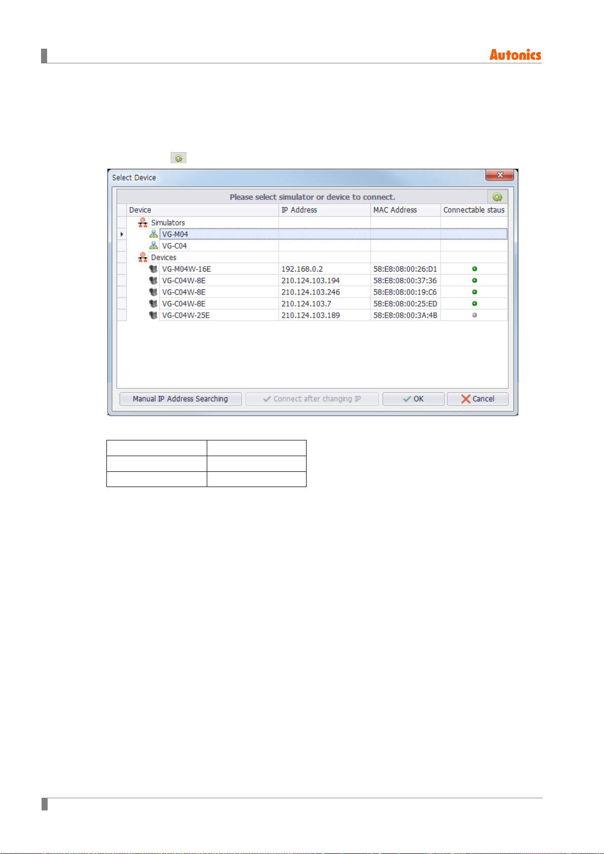
Change the network settings in Vision Master to connect with a device (vision sensor).
When executing Vision Master, Select Device window appears. Simulator or connected devices
are displayed in the window. You can check connectable devices and connected devices using
Refresh icon ( ) on the top of the window.
Factory default of the device (vision sensor) is as follows.
IP address 192.168.0.2
Subnet mask 255.255.255.0
Gateway 192.168.0.1
44 © Copyright Reserved Autonics Co., Ltd.
Page 45
6 Vision Sensor Program [Vision Master]
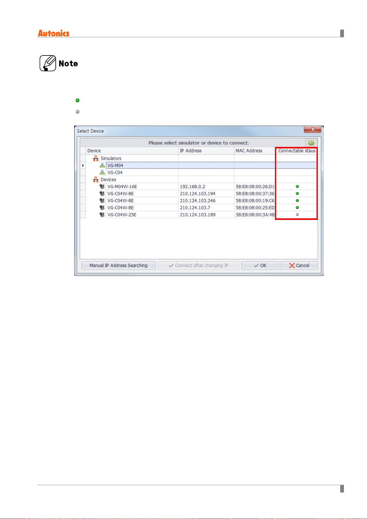
A list of the currently connected vision sensor is displayed. After checking “connectable status”
indicator, and connect a vision sensor.
: Connectable
: Unconnectable
- The vision sensor is not connectable because it is connected to another PC already.
© Copyright Reserved Autonics Co., Ltd. 45
Page 46
6 Vision Sensor Program [Vision Master]
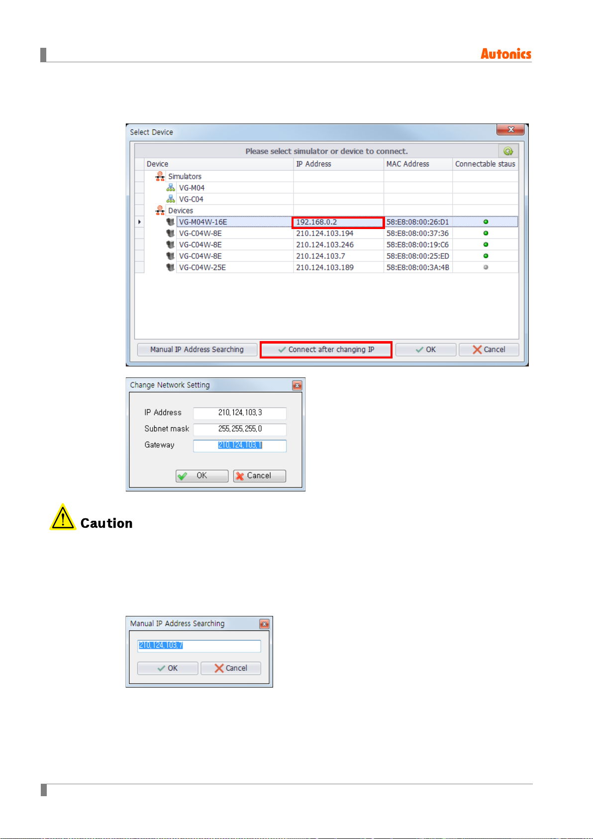
(1) Change of device IP address
You can change IP address of the device to connect.
1st Select the device to connect, and click “After IP change, connect” button.
2nd Change IP address in Change Network Setting window.
If changed IP address is same with another IP address which is used in another PC of device,
network error can occurs due to IP address conflicts.
(2) Manual search of IP address
If a device is not recognized while it is connected, click “Manual IP Address Searching” and
search IP address of the device to connect.
(This is usable only when Gateway of the device and PC are same.)
46 © Copyright Reserved Autonics Co., Ltd.
Page 47
6.4 Start and Exit
6.4.1 Start
Double-click Vision Master icon in the desktop or select Start > Program > Vision Master to start
the program.
6.4.2 Exit
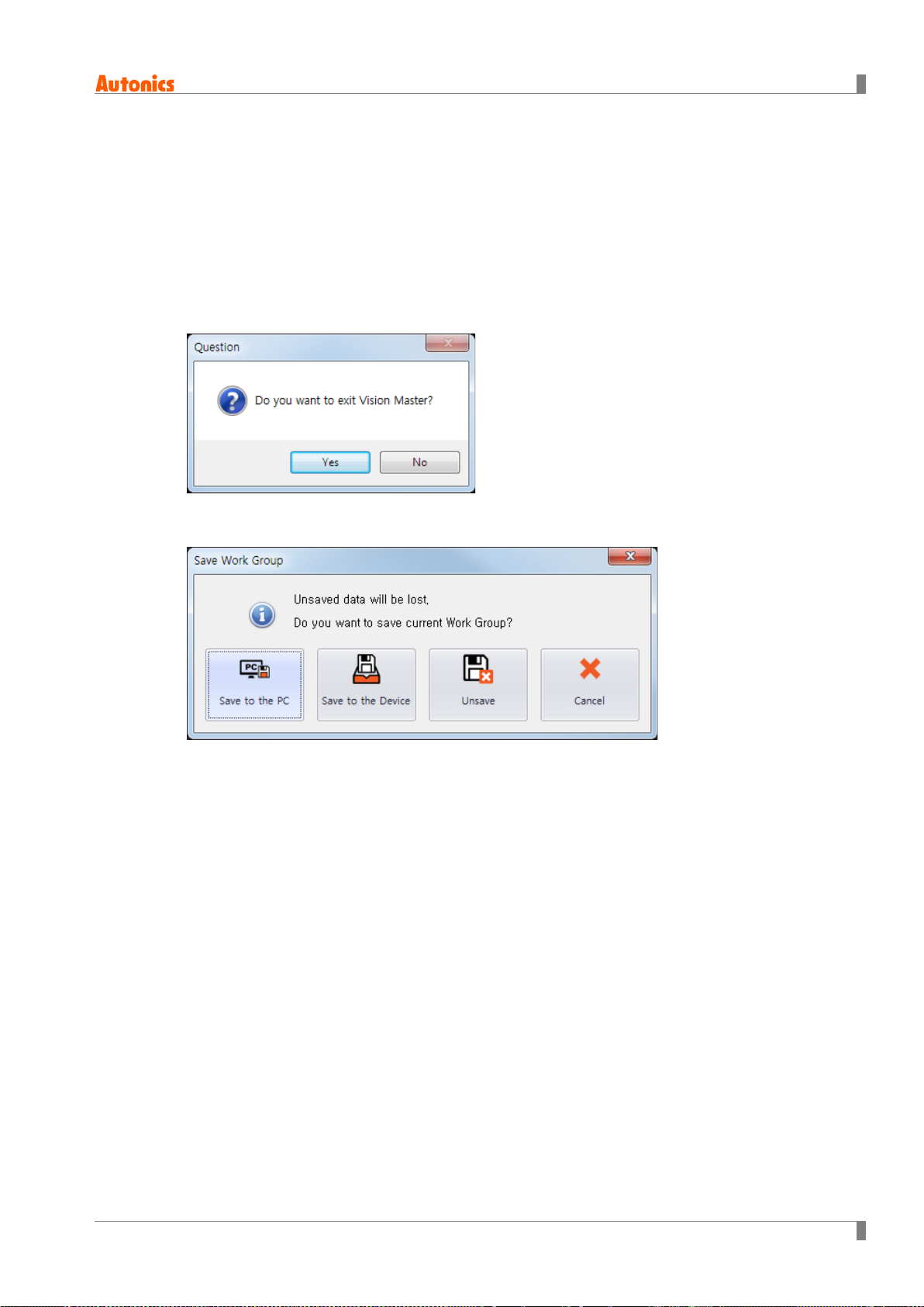
Click [X] button on the top right corner of the screen or ‘exit’ in the file menu to end the program.
Since work group, parameter settings, and data are not saved automatically, please make sure
that you have saved the work group before you exit.
6 Vision Sensor Program [Vision Master]
© Copyright Reserved Autonics Co., Ltd. 47
Page 48
6 Vision Sensor Program [Vision Master]
No.
Item
Description
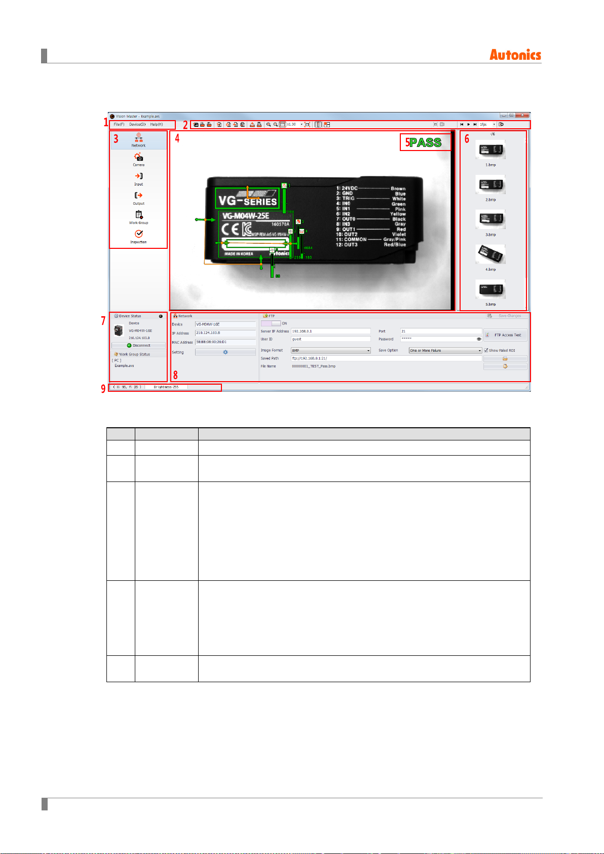
1
Menu
Displays Vision Master menus by category.
6.5 Vision Master Screen Layout
The program screen is divided into sections as shown in the preceding screenshot and each
section is composed of the following items.
2 Tool bar
Setting
3
menu
Image
4
window
Inspection
5
result
Displays icons of frequently used menu, settings of image window, camera
snap, or etc.
Displays vision sensor setting parameter menu.
If none of device of connected, it is available to connect simulator to
register work group and inspection test.
Activation of the setting menu depends on the type of the connected device
(simulator or device)
- Simulator connection: work group, inspection
- Device (vision sensor) connection: network, camera, input, output, work
group, inspection
Displayed image is different according to the mode and settings.
- Setting mode: displays a taken image by vision sensor or selected image
between master image to register work group and loaded image to preview
window.
- Operation mode: displays taken images according to the “View Result
Image” settings. Please refer to '6.6.6 Inspection'.
Displays inspection result (Pass/Fail) of work group.
48 © Copyright Reserved Autonics Co., Ltd.
Page 49
6 Vision Sensor Program [Vision Master]
No.
Item
Description
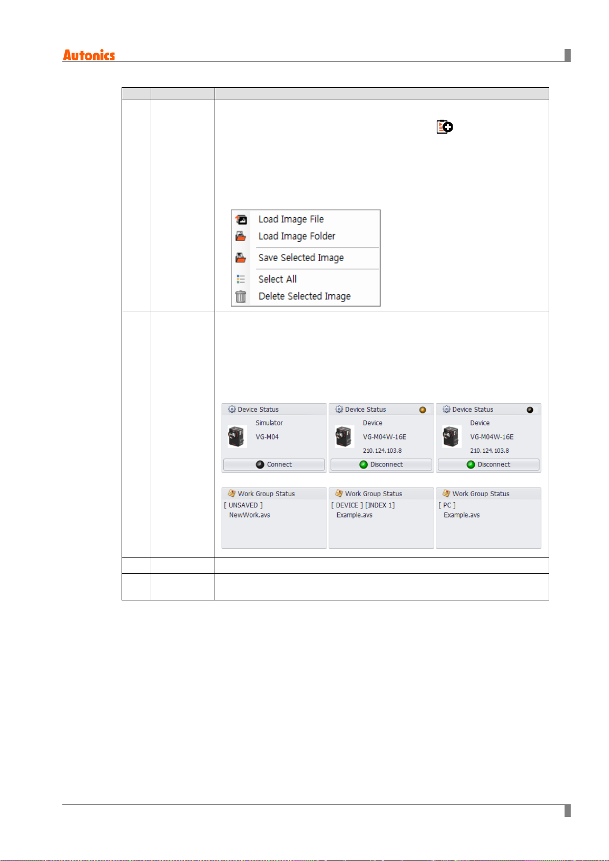
Displays loaded images.
If the ‘Add Taken Image to Preview Window’ icon ( ) is activated,
preview window displays images taken by the vision sensor, which are
different according to the mode and settings.
- Setting mode: displays all images taken by the vision sensor.
- Operation mode: while inspecting, displays taken images according to the
‘View Result Image’ settings. Please refer to '6.6.6 Inspection'.
Preview
6
window
Right click in the preview window to display setting menu as follows.
Displays status information of the device and work group.
- Device status
: displays information of simulator or device (vision sensor) connected to
Vision Master. It is available to connect or disconnect device. Indicator on
the top right side enables to check the communication status between
Vision Master and the device, when the device is connected. The indicator
flashes while data communication.
Status
7
information
- Work group status: displays status of currently registered work group.
8 Parameter Displays specific parameters in the setting menu.
9
Image
information
Displays brightness value and pixel coordinate of the point where the
mouse cursor is pointing on the image window.
© Copyright Reserved Autonics Co., Ltd. 49
Page 50
6 Vision Sensor Program [Vision Master]
No.
Icon
6.5.1 Menu
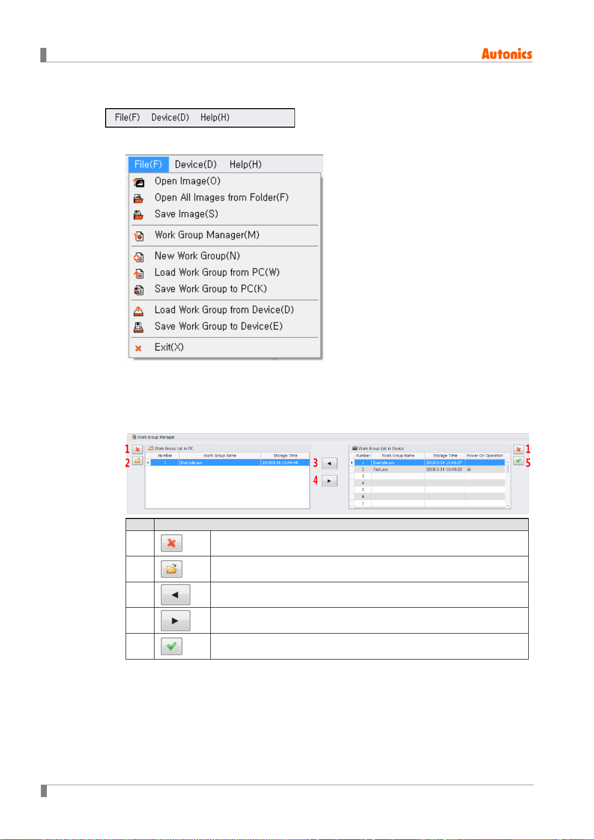
(1) File
Open Image: Opens the image to inspect.
Open All Images from Folder: Opens the folder of images to inspect.
Save Image: Saves the image displayed in Image window.
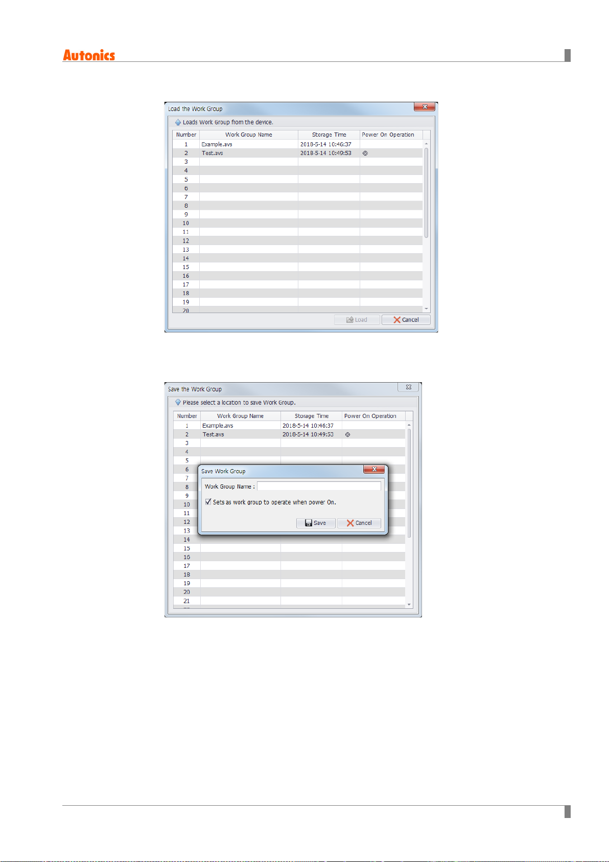
Work Group Manager: Displays a list of work group saved in the PC or device to copy,
delete, or save. It is available to set work group to use when the device turns on.
1
2
3
4
Deletes selected work group.
Selects a folder in the PC to load work group from.
Copies work group from the device to the PC.
Copies work group from the PC to the device.
5
Selects work group to operate when the device turns on.
New Work Group: Registers new work group.
Load Work Group from PC: Loads work group from the local disk of PC.
Work groups are saved in the default folder [C:\Users\ (Account name)
\Documents\Autonics\Vision Master\Work] or the folder designated by user.
Save Work Group to PC: Saves work groups registered and set in Vision Master to the
local disk of PC.
Work groups are saved in the default folder [C:\Users\ (Account name)
\Documents\Autonics\Vision Master\Work] or the folder designated by user.
50 © Copyright Reserved Autonics Co., Ltd.
Page 51
6 Vision Sensor Program [Vision Master]
Load Work Group from Device: Loads work group from the device (vision sensor).
Save Work Group to Device: Saves work groups registered and set in Vision Master to
the device (vision sensor). Click number of work group to save to set the name of work
group. At that moment, selected work group can be set as operating work group when
the device turns on. Work group can be registered and saved up to 32.
Exit: Exits Vision Master.
© Copyright Reserved Autonics Co., Ltd. 51
Page 52
6 Vision Sensor Program [Vision Master]
(2) Device
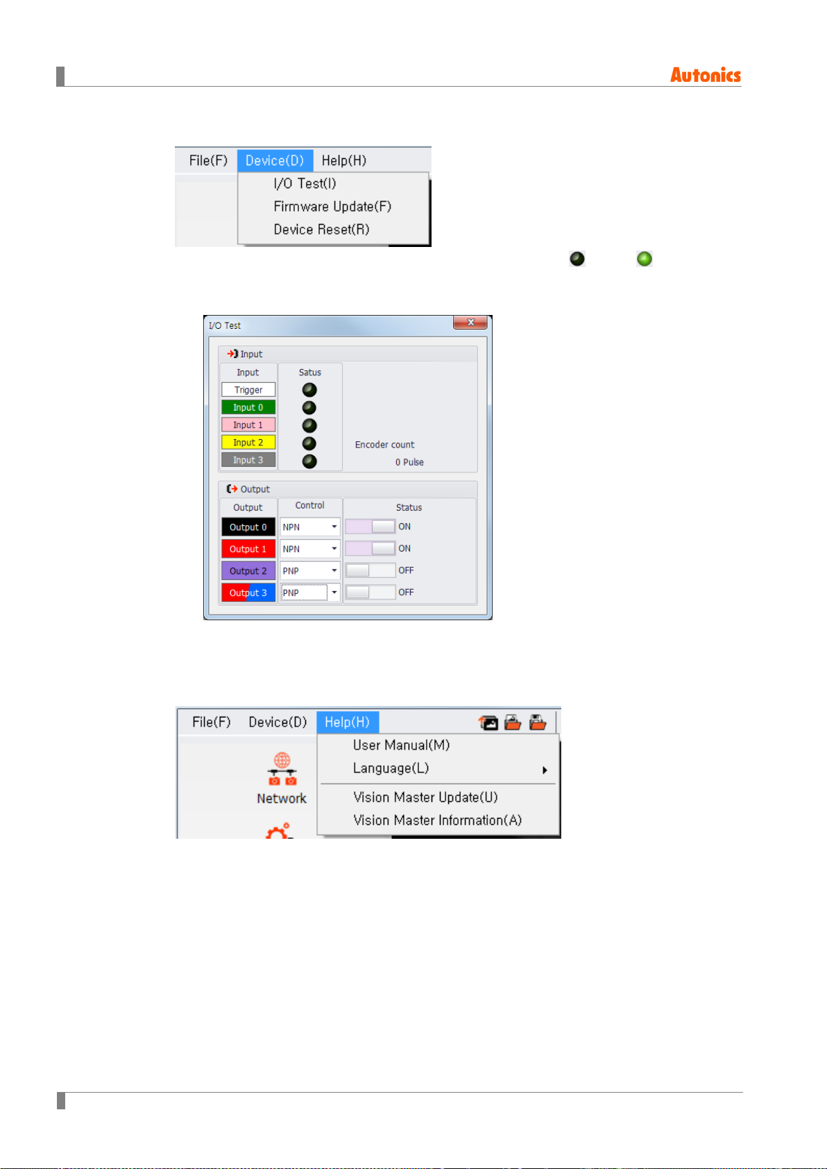
I/O Te s t: Displays input status with the indicators (no input: / input: ). Also it is
available to set control output type (NPN/PNP) and whether use each output or not.
I/O test is only for testing output, so that it is not associated with settings of output
parameter
Firmware Update: Updates firmware version of the device (vision sensor).
Device reset: Resets the device, deleting saved work group and set parameters from
the device.
(3) Help
User Manual: Loads user manual.
Language: Changes program language.
Vision Master Update: Updates version of Vision Master.
Vision Master Information: Displays information about version of Vision Master and
device firmware.
52 © Copyright Reserved Autonics Co., Ltd.
Page 53
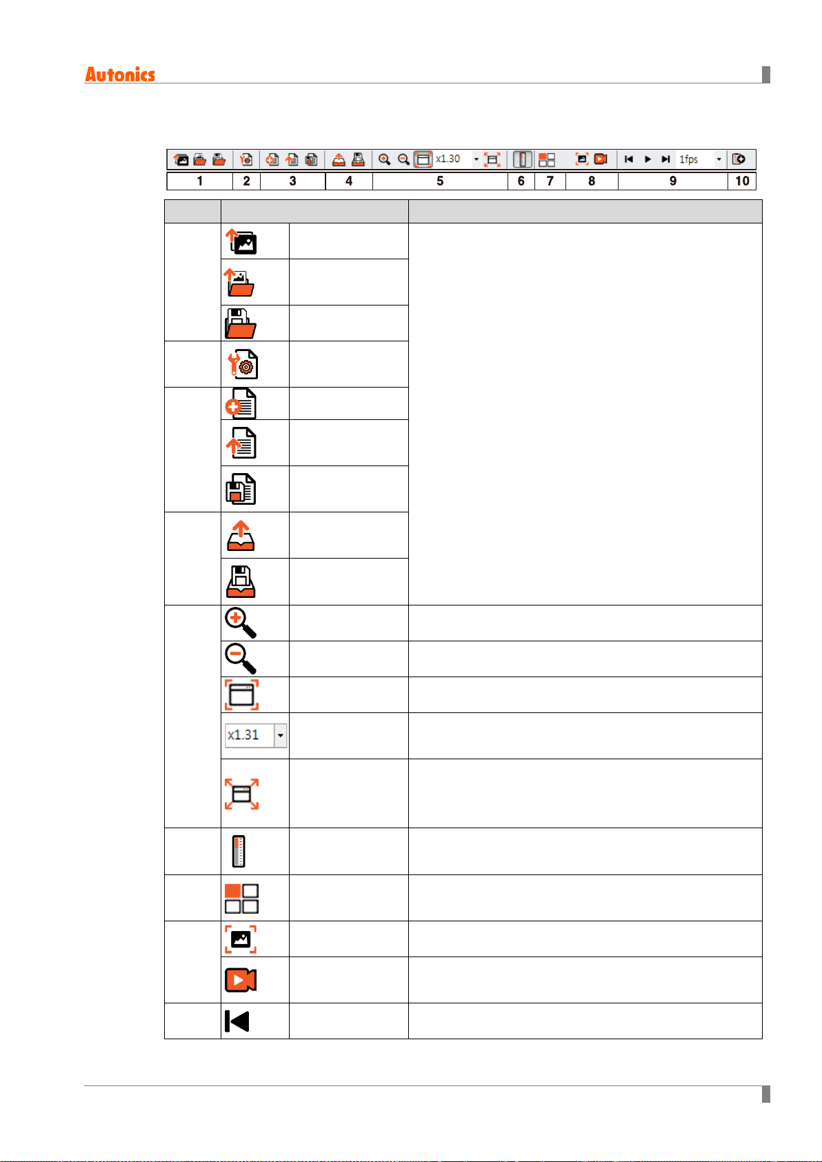
6.5.2 Toolbar
Section Icon Description
6 Vision Sensor Program [Vision Master]
Open Image
1
2
3
4※1
Open All Images
from Folder
Save Image
Work Group
Manager
New Work Group
Please refer to '(1) File' in '6.5.1 Menu'.
Open Work Group
from PC
Save Work Group
to PC
Open Work Group
from Device
Save Work Group
to Device
Zoom in Enlarges image.
Zoom out Reduces image.
Fit to Window Adjusts the size of the image to fit to the image window.
5
Resize image.
Image Scale
- Setting range: ×0.5, ×1, ×2, ×4, ×8, ×16
Displays image in full screen mode.
Full Screen
To turn off full screen view, press ESC key or double click
mouse button.
Displays the pass range of inspection which set in work
6
7
Show Bar Gauge
Multi View
(4 channels)
※3
group as bar gauge.
Displays inspection status of maximum 4 vision sensors at
the same time.
Snap Takes an image with the camera of vision sensor.
※1, ※2
8
Continuous Snap
9
Backward Loads previous image from images in preview window.
Takes multiple images with the camera of vision sensor,
according to the set number of frame per second (fps).
© Copyright Reserved Autonics Co., Ltd. 53
Page 54
6 Vision Sensor Program [Vision Master]
Section Icon Description
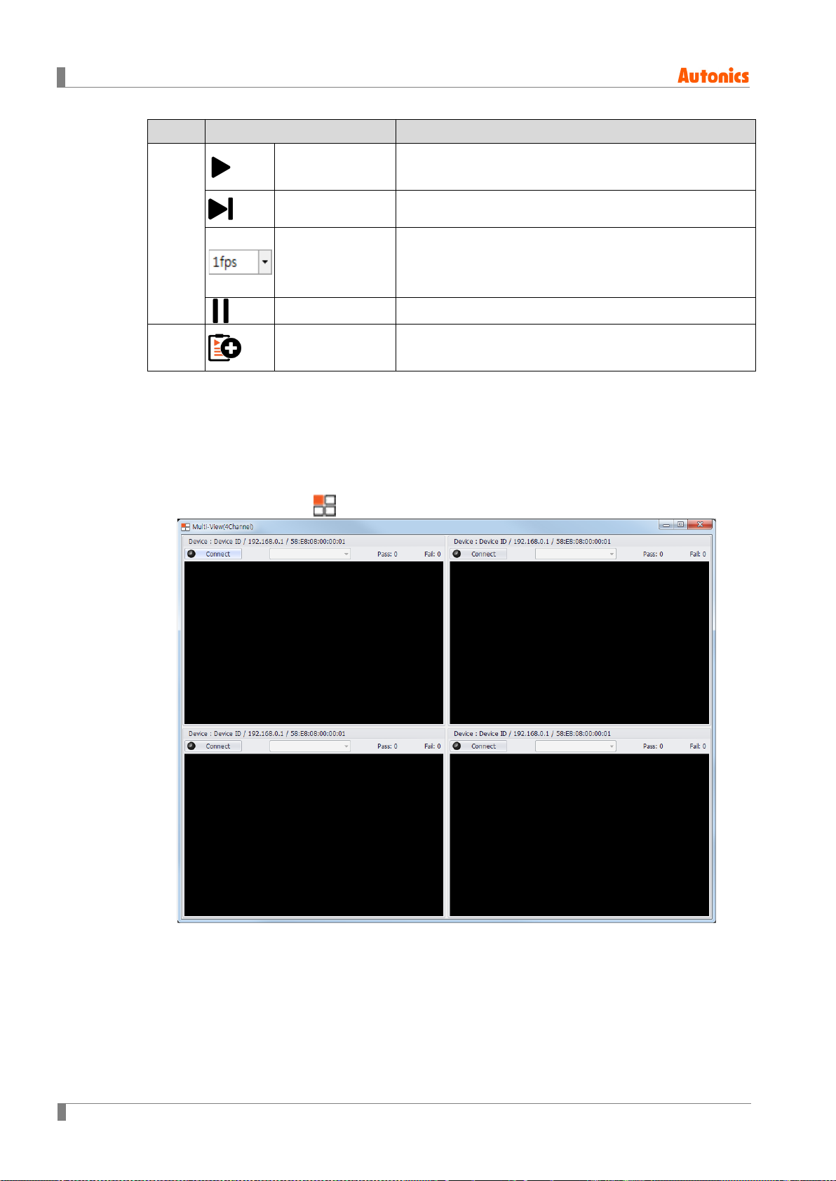
Loads images consecutively from images in preview
window.
Selects the image playing speed for displaying images from
preview window.
- Setting range: 4fps, 2fps, 1fps, 1/ 2fps, 1/4fps
Adds taken images to preview windows.
10※1
Play
Forward Loads next image from images in preview window.
Image Play Speed
Pause Pauses playing of images from preview window.
Add Taken Image
to Preview Window
※1. It is not displayed in simulator operation.
※2. It is displayed only when the camera trigger mode is set to ‘free-run trigger’ or ‘internal
trigger’.
※3. Use Multi View function as flows.
1st Click Multi View icon ( ) to open Multi View window as flows.
54 © Copyright Reserved Autonics Co., Ltd.
Page 55
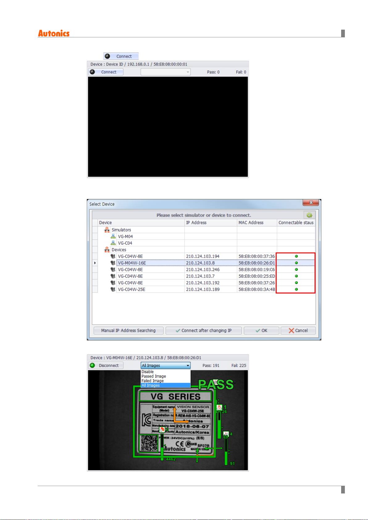
2nd Click on the top.
6 Vision Sensor Program [Vision Master]
3rd Select the device to connect.
You can only select devices which of the connectable status indicator is turned on in green
color.
4th Set View Result Image.
Inspection result of the running device (vision sensor) is displayed in the image window.
© Copyright Reserved Autonics Co., Ltd. 55
Page 56
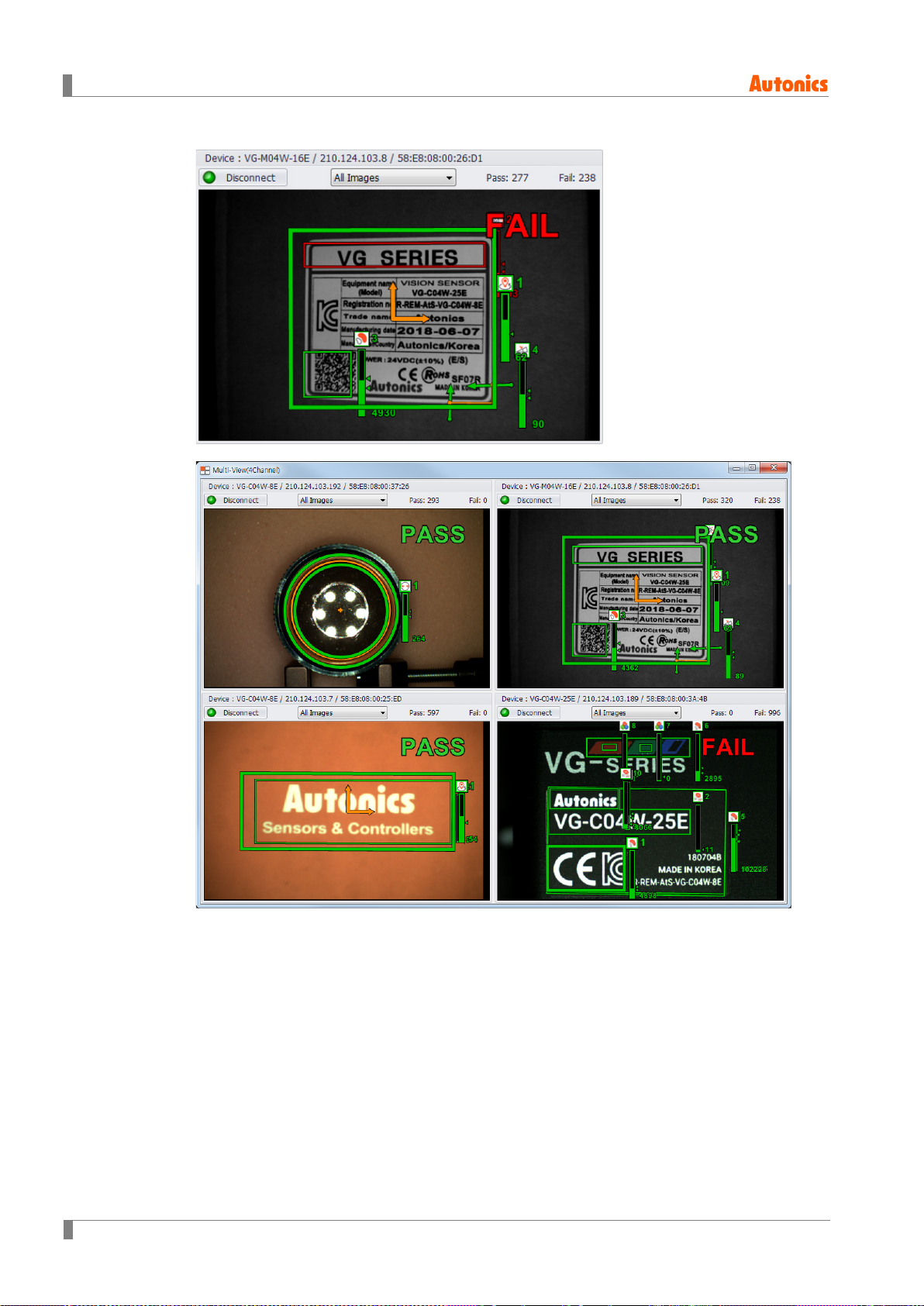
6 Vision Sensor Program [Vision Master]
5th You can monitor statistics of Pass/Fail result.
6th You can monitor inspection status of maximum 4 vision sensors at the same time.
56 © Copyright Reserved Autonics Co., Ltd.
Page 57
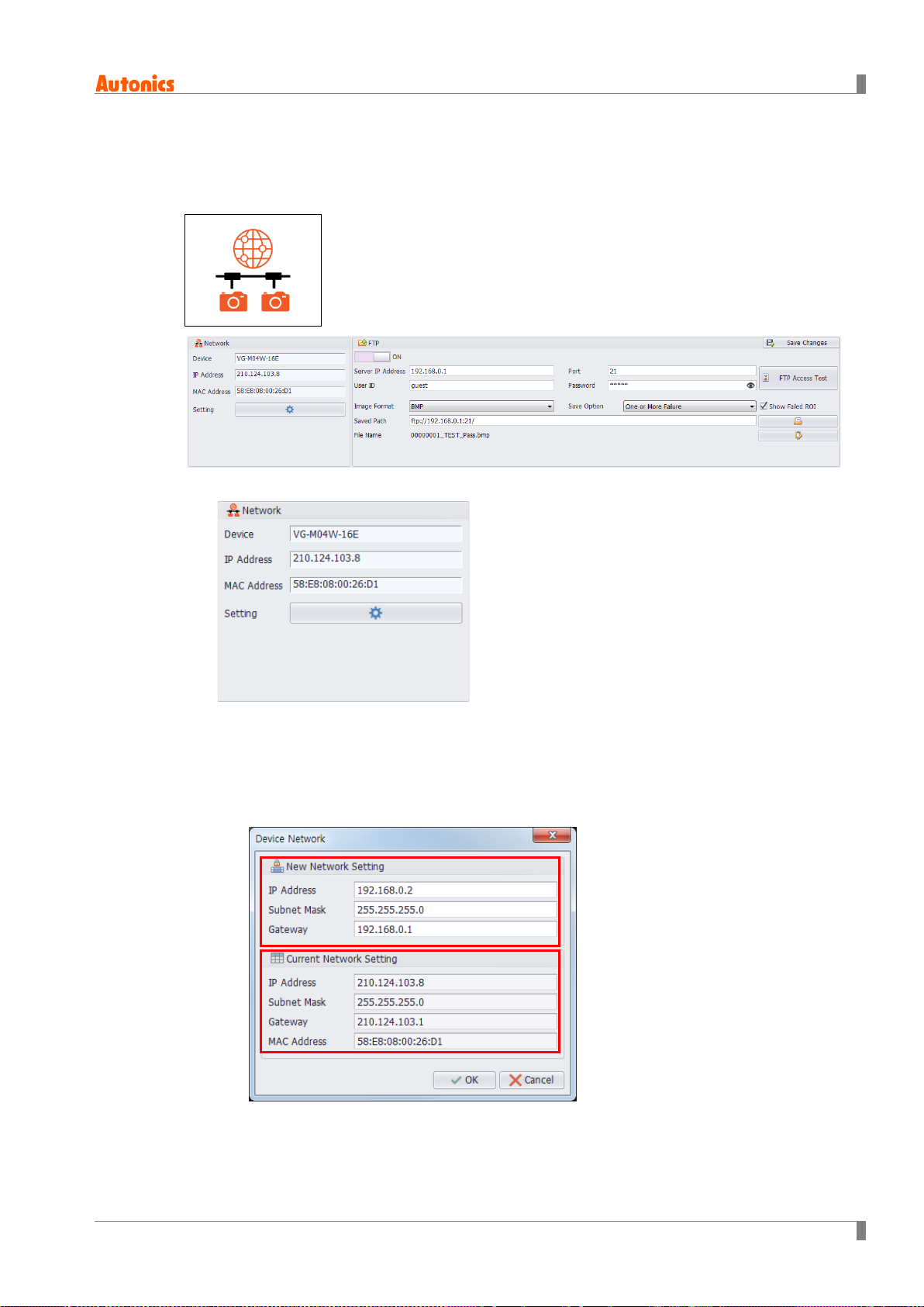
6.6 Setting Menu
6.6.1 Network
(1) Network
6 Vision Sensor Program [Vision Master]
It is available to set vision sensor and PC network.
Device: Displays currently connected vision sensor to Vision Master.
IP / MAC Address: Displays IP / MAC address of the connected device.
Setting: Changes IP address setting of the currently connected device.
[Current Network Setting] is network information of the currently connected device. To
change network setting, enter new information in [New Network Setting].
© Copyright Reserved Autonics Co., Ltd. 57
Page 58
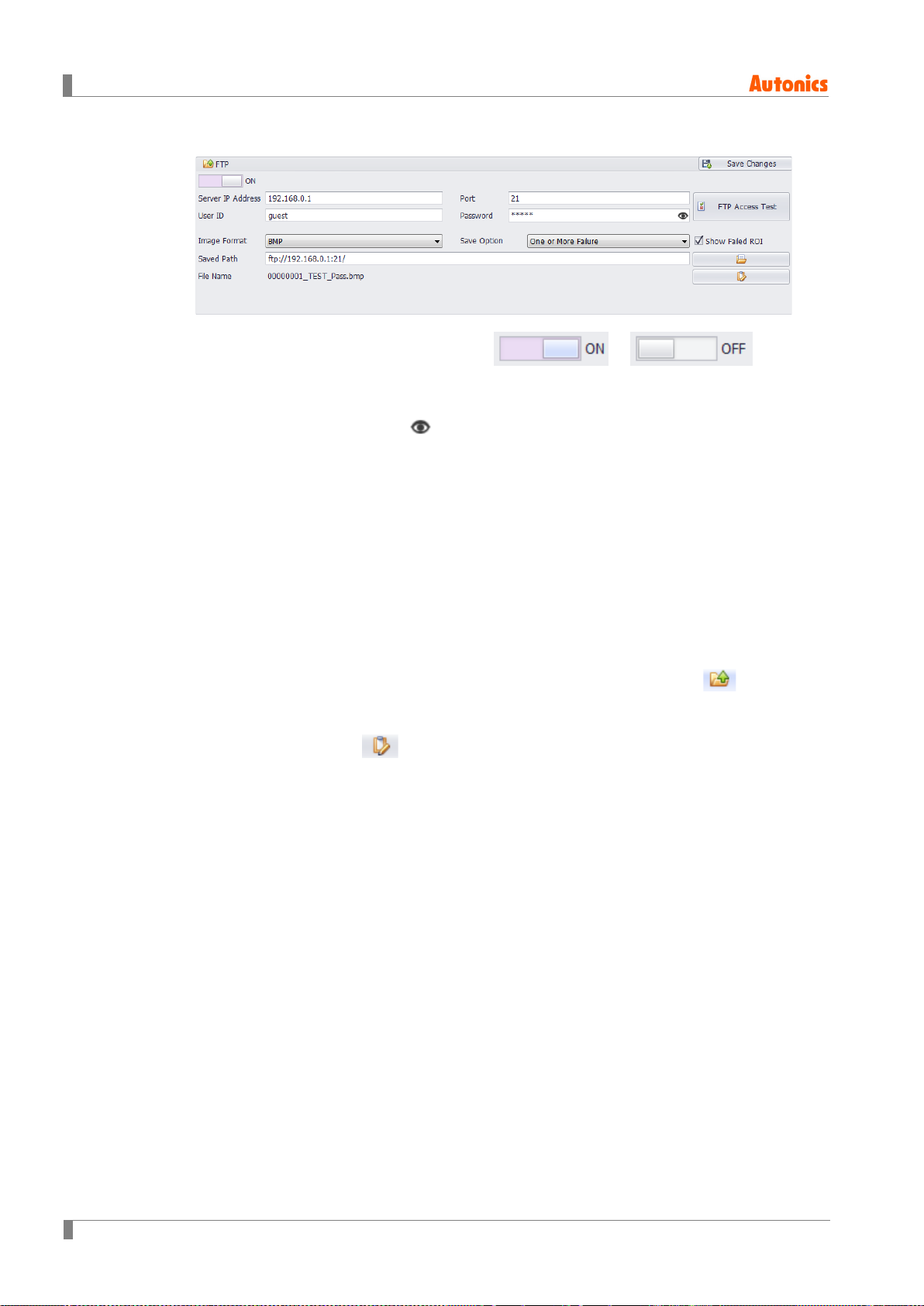
6 Vision Sensor Program [Vision Master]
(2) FTP
Transmits inspection result images saved in vision sensor memory to FTP server.
Select whether to use FTP function or not. ( / )
Server IP Address / Port: Enter IP address and port of FTP server.
User ID / Password: Enter user ID and password.
※If Show Password icon ( ) is clicked, being entered password is displayed in
characters, not ‘ * ‘.
FTP Access Test: Checks status of connection to FTP server.
Image format: Select image format to be saved when transmitting image to FTP server.
You can select between BMP (*.bmp) and JPG (*.jpg).
Save Option: Sets conditions for saving images.
- All Pass: Only saves images which pass all the inspection items in work group.
- One or More Failure: Saves images which failed to pass one or more among
inspection items in work group.
※If Show Failed ROI check box is checked, ROI which failed to pass inspection is
marked in the result image.
Saved Path: Enter location in server to save the result image.
※When designating folder to upload, click ‘Upload Folder Path’ icon ( ) on the right
side. You can see the list of folder in the server.
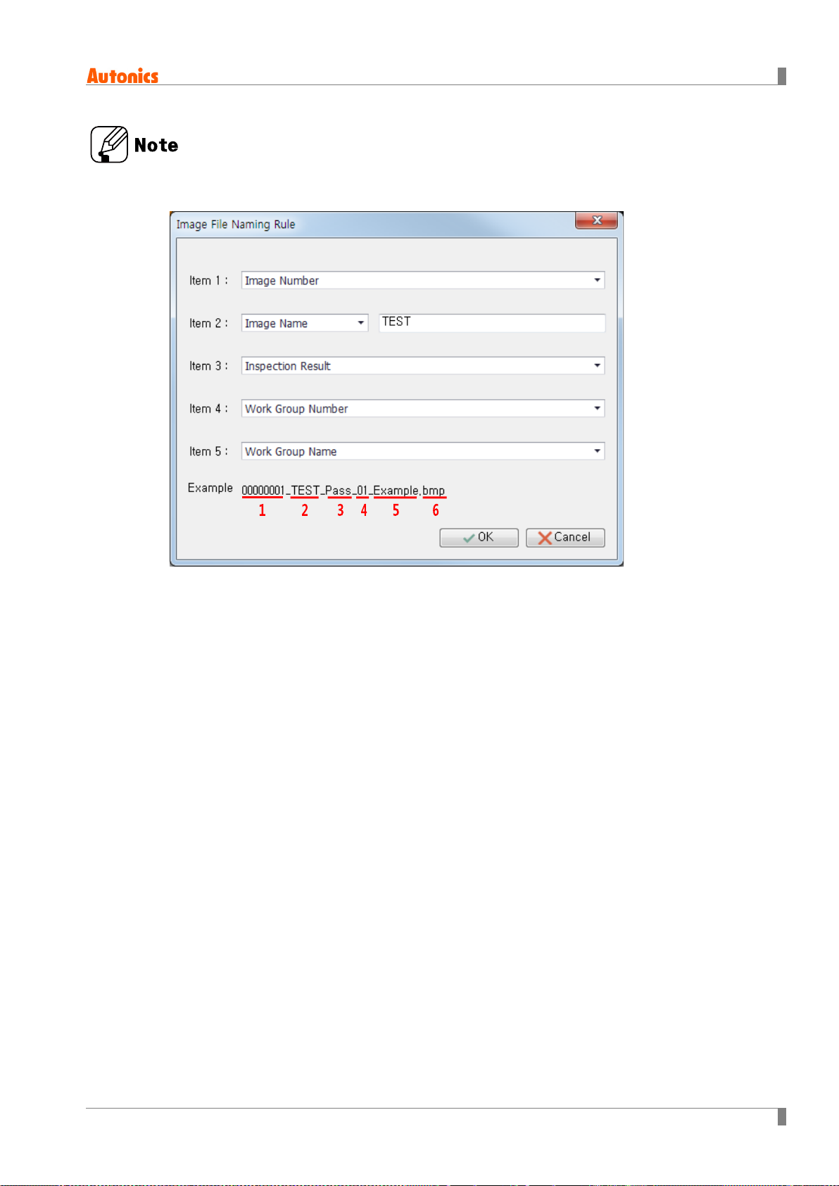
File Name: Sets file name of image to transmit to the FTP server. Click ‘Image File
Naming Rule’ icon ( ) on the right side to set name.
58 © Copyright Reserved Autonics Co., Ltd.
Page 59
6 Vision Sensor Program [Vision Master]
Image file naming rule is as flows.
Item can be set up to 5, and you can customize the order of the items.
Image Number: It is number of taken image. It is necessary for image file naming.
Image Name: User can set image name using only Korean, English alphabet, number, and
some of special characters (except “ < > ? * / \ |)
Inspection Result: Displays inspection result of Pass/Fail.
Work Group Number / Work Group Name: Displays number and name of inspecting
work group.
Image format filename extension: It is image format filename extension. It displays
BMP (*.bmp) or JPG (*.jpg).
© Copyright Reserved Autonics Co., Ltd. 59
Page 60
6 Vision Sensor Program [Vision Master]
6.6.2 Camera
6.6.2.1 Trigger
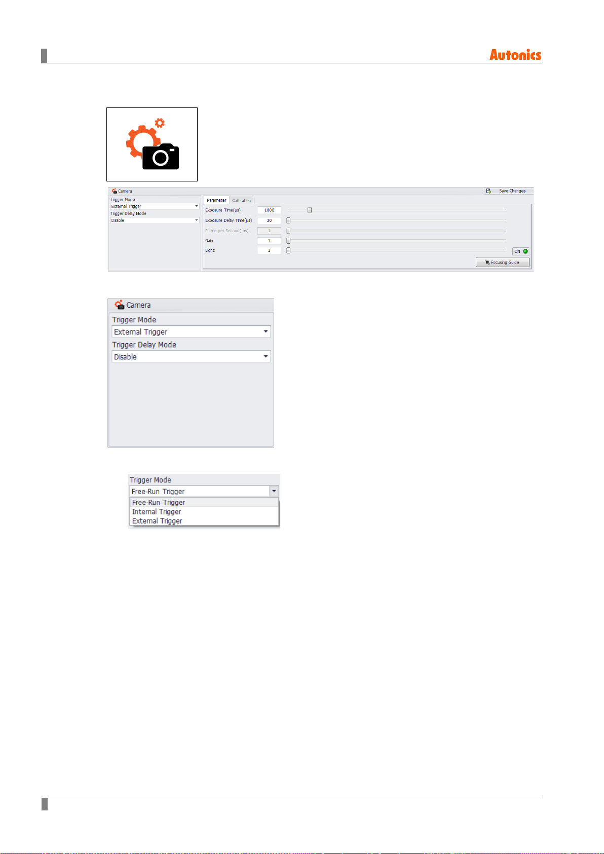
(1) Trigger mode
Free-Run trigger: Takes images with the maximum trigger speed that can occur in the
sensor. (fixed to 60fps)
Internal Trigger: Takes image by occurring trigger in the sensor (1 to 60fps)
External Trigger: Takes image with external input signal as trigger. If you use external
trigger mode, you can use trigger delay mode.
60 © Copyright Reserved Autonics Co., Ltd.
Page 61
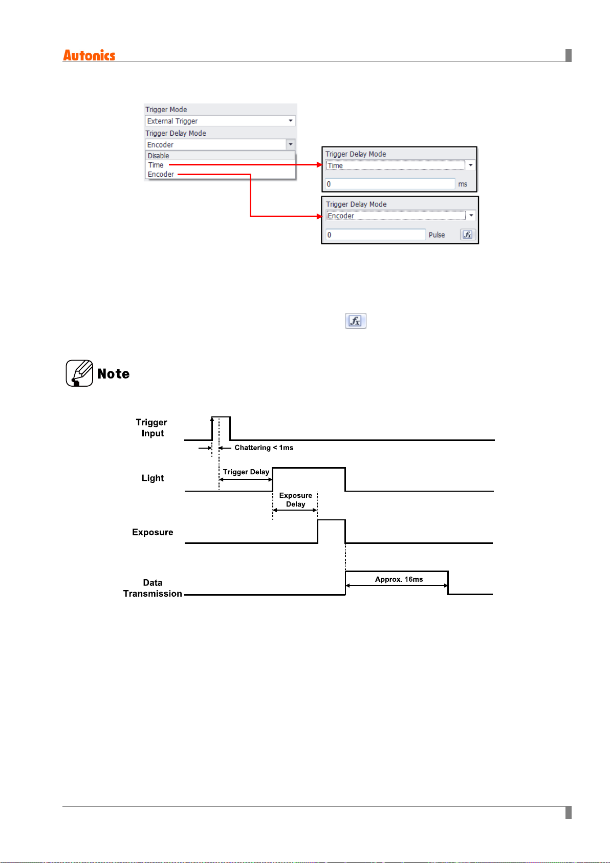
(2) Trigger Delay Mode
6 Vision Sensor Program [Vision Master]
Trigger delay means delayed time from inputting moment of external trigger to actual
starting moment of image taking.
Time: Sets the trigger delay in time unit. Setting range is from 0 to 60,000ms.
Encoder: Sets the trigger delay in unit of the number of pulse. Setting range is from 0 to
16,000,000 pulses.
Click ‘Encoder Delay Pulse Calculator’ ( ) and enter moving distance and distance
resolution of encoder to calculate pulse value according to um/pulse or pulse/um
setting value.
After setting the trigger delay mode, timing diagram of trigger input is shown as follows.
© Copyright Reserved Autonics Co., Ltd. 61
Page 62
6 Vision Sensor Program [Vision Master]
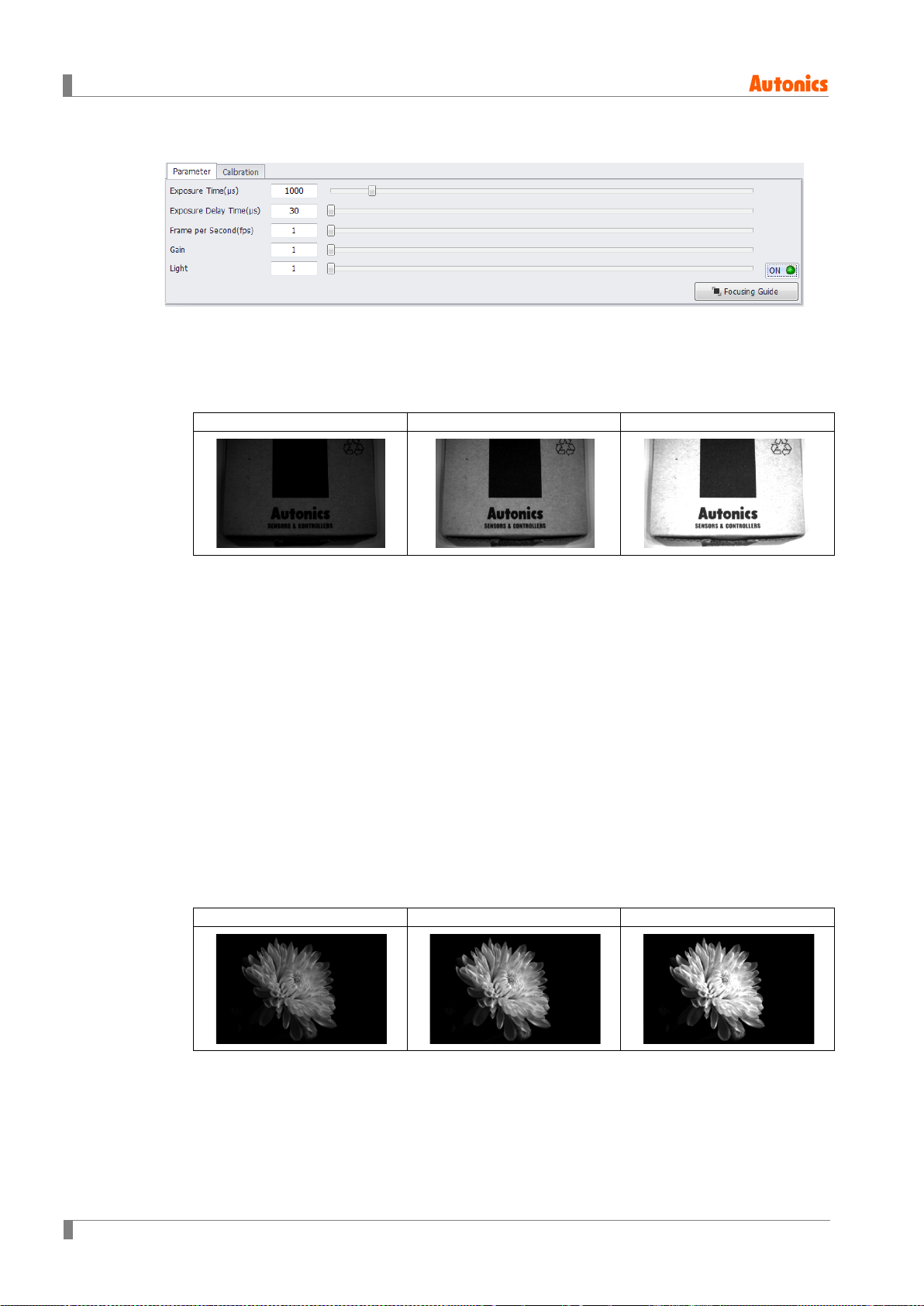
Short exposure time
Proper exposure time
Long exposure time
Gain 1 level
Gain 8 level
Gain 16 level
6.6.2.2 Parameter
(1) Exposure time
Exposure time is the time span for which the vision sensor is exposed to the light.
The longer exposure time is, the brighter the taken image is, and the shorter exposure time
is, the darker the taken image is.
Setting range is from 20 to 10,000us.
(2) Exposure delay time
Exposure delay time delays the light receiving point of vision sensor.
Setting range is from 30 to 10,000us.
(3) Frame per second
Frame per second is Frame rate which is the number of images taken per 1 second.
It is settable only when the trigger mode is set to “internal trigger”.
Setting range is from 1 to 60fps.
※In the external trigger mode, the vision sensor takes images with external input signal, so
that you cannot set the frame per second.
※In the free-run trigger mode, the vision sensor takes images at the fastest speed which the
vision sensor can.
(The shorter exposure time is, the faster the vision sensor can take.)
(4) Gain
It is adjusting gain of CMOS image sensor.
As higher gain level makes image brighter, increased noises makes resolution low.
Setting range is from the level 1 to 16.
62 © Copyright Reserved Autonics Co., Ltd.
Page 63
6 Vision Sensor Program [Vision Master]
Light level 1
Light level 8
Light level 16
(5) Light
You can set whether to use inner LED light or not. (Use: /not use: )
Light is synchronized with trigger signal and exposure time.
Setting range is from the level 1 to 16.
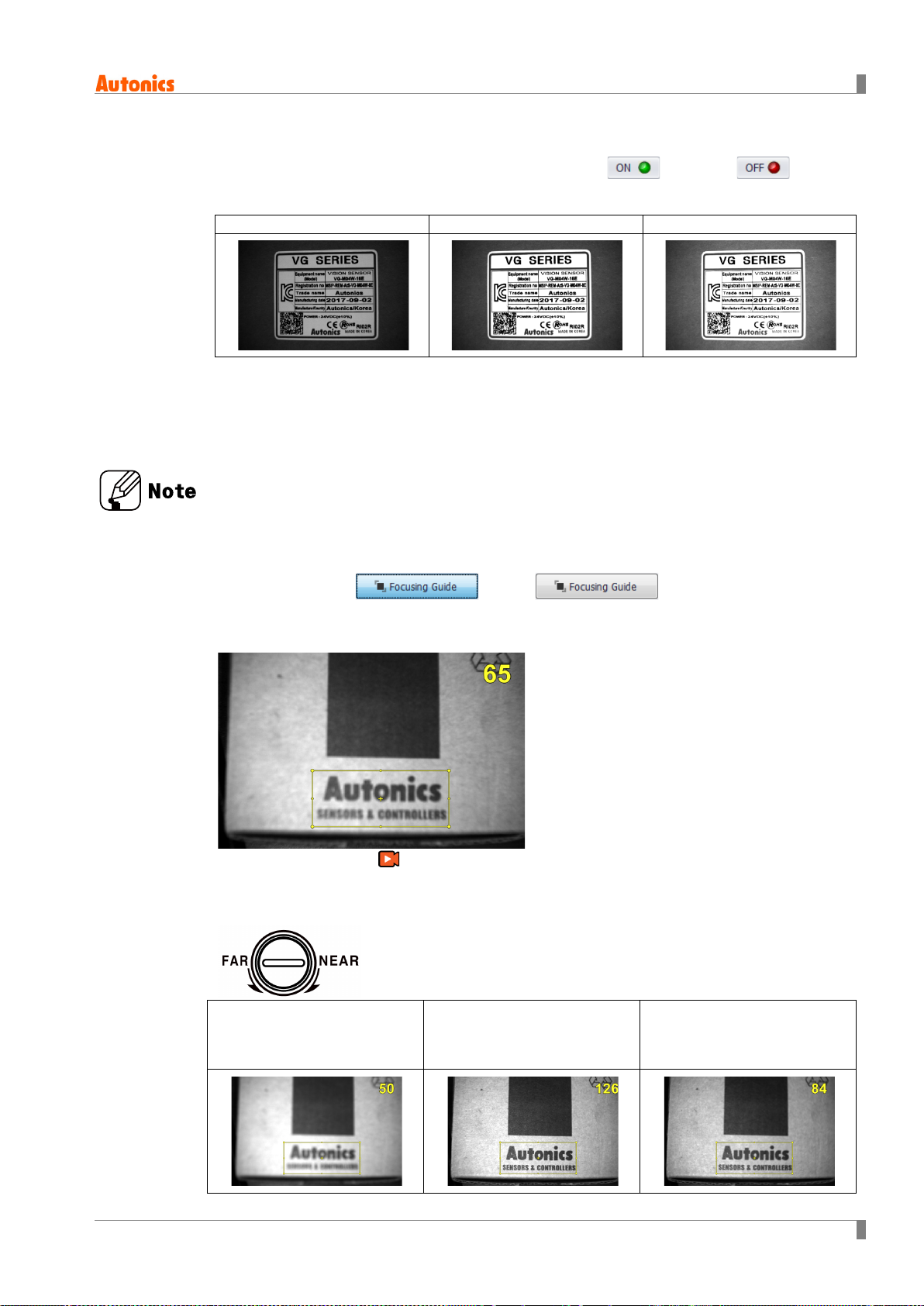
(6) Focusing guide
Focusing guide makes adjusting image focus with the focus adjuster convenient.
After setting ROI of the sensing target and checking the focusing guide value, rotate the
focus adjuster to the point where the focusing guide value is the highest and fix it at the
point to use.
How to adjust focus with focusing guide.
1st Click focusing guide button.
Focusing guide ON( ) /OFF ( )
2nd In the image window, the focusing guide value and area is displayed on the master image.
Adjust the area to focus on. The higher the focusing guide value is, the clearer focus on the
image is.
3rd Click continuous snap ( ) on the toolbar on the top.
4th Checking consecutively taken images, rotate the focus adjuster to the FAR or NEAR
direction. Since initial setting is unknown, rotate the focus adjuster to both FAR and NEAR
directions and fix the adjuster at the point where the focusing guide value is the highest.
When sensing target is in near
→ rotate to the NEAR
direction.
Focus adjusting is finished. When sensing object is far
→ rotate to the FAR direction.
© Copyright Reserved Autonics Co., Ltd. 63
Page 64
6 Vision Sensor Program [Vision Master]
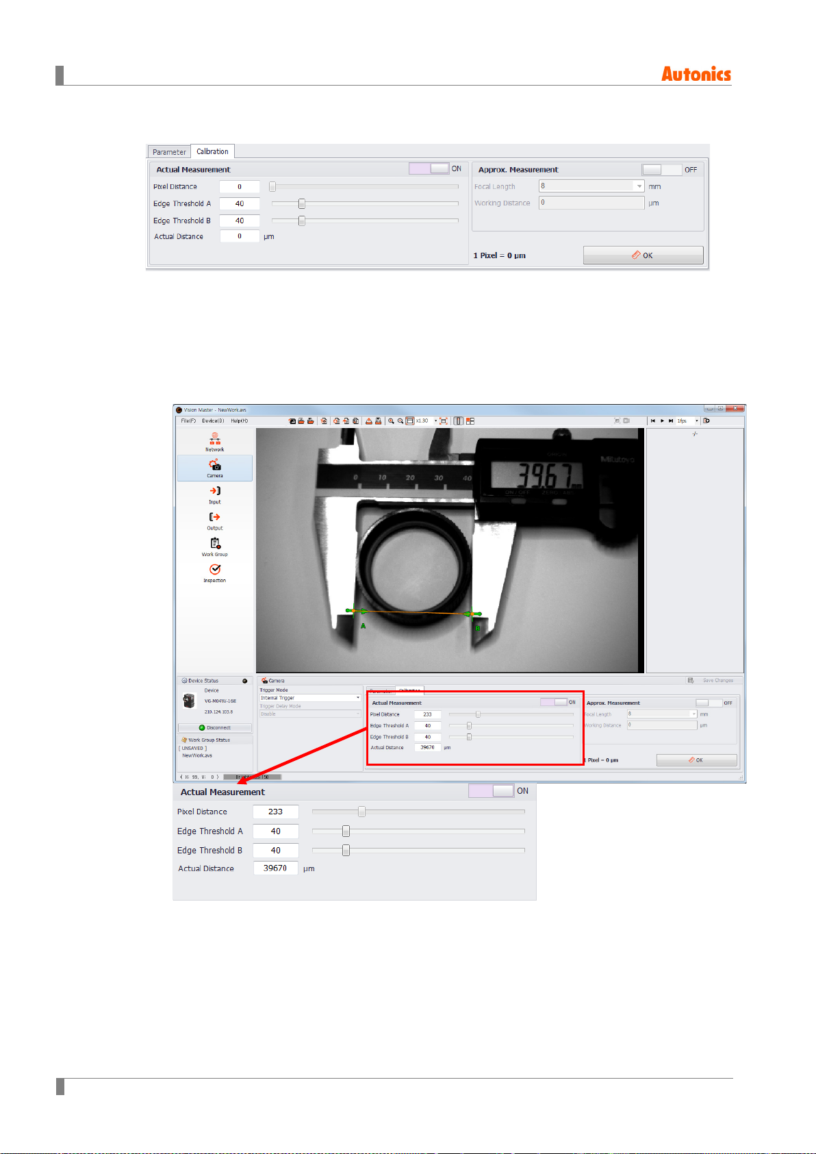
6.6.2.3 Calibration
Calibration has two method of ‘actual measurement’ and ‘approximate measurement’. Since
those methods cannot be set at the same time, you have to select one method of them.
Claibration calulates ㎛ per 1 pixel to register.
Since the vision sensor measures distance in unit of pixel, use calibration function for calculating
in unit of ㎛.
(1) Actual measurement
Pixel Distance: It displays distance between edge A and edge B in pixel.
Edge Threshold A/B: It is for setting edge threshold to detect edge.
With the higher edge threshold value, edge of high contrast is detected, and with the
lower edge threshold value, edge of low contrast can be also detected.
Actual Distance: It is for entering actual distance between two edges in unit of ㎛.
64 © Copyright Reserved Autonics Co., Ltd.
Page 65
6 Vision Sensor Program [Vision Master]
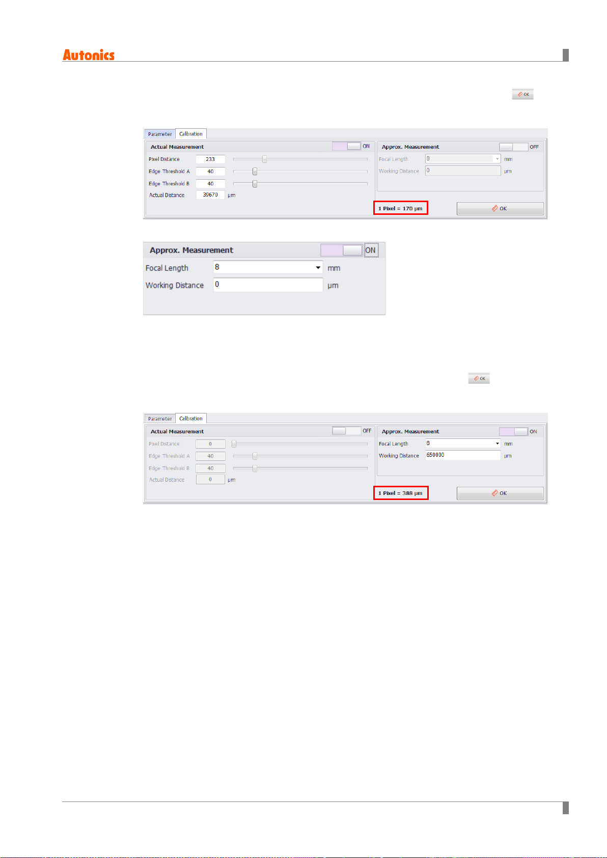
After setting the edge threshold value and entering the actual distance, click ‘OK’
( )
the right bottom corner to register values after calculating distance per 1 pixel into unit of ㎛
based on the set values in ‘Actual Measurement’ tab.
(2) Approximate measurement
Focal Length: It is for selecting effective focal length of the connected device (vision
sensor).
Working Distance: It is for entering distance between sensing target and the vision
sensor.
After selecting focal length and entering the working distance, click ‘OK’
( )
in the right
bottom corner to register values after calculating distance per 1 pixel into unit of ㎛ based
on the working distance and FOV by effective focal length.
in
© Copyright Reserved Autonics Co., Ltd. 65
Page 66
6 Vision Sensor Program [Vision Master]
6.6.3 Input
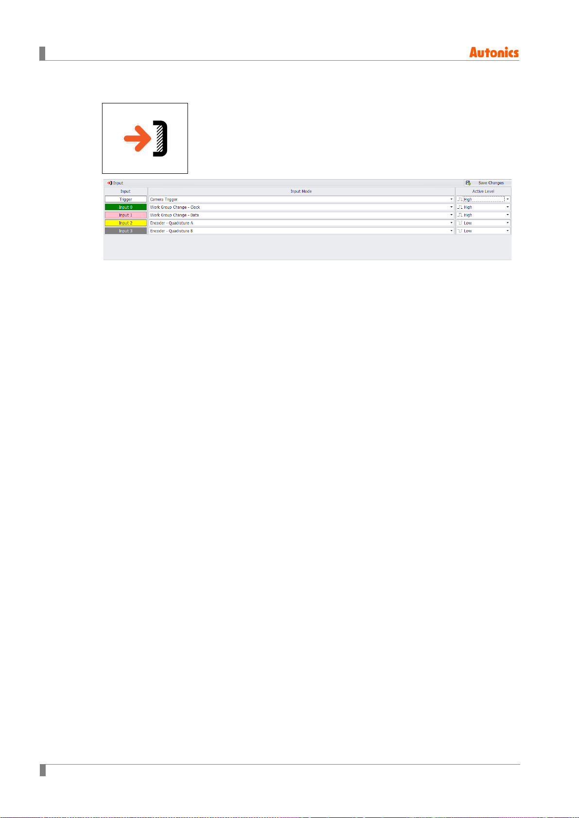
(1) Input mode
Trigger input (TRIG): The selected trigger mode which set in the camera menu is the
image taking signal.
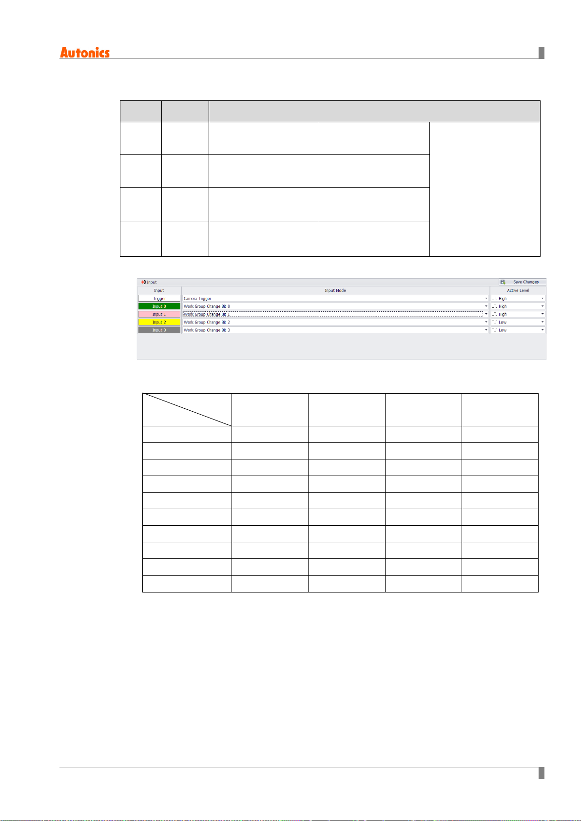
Work group change (IN0 to IN3)
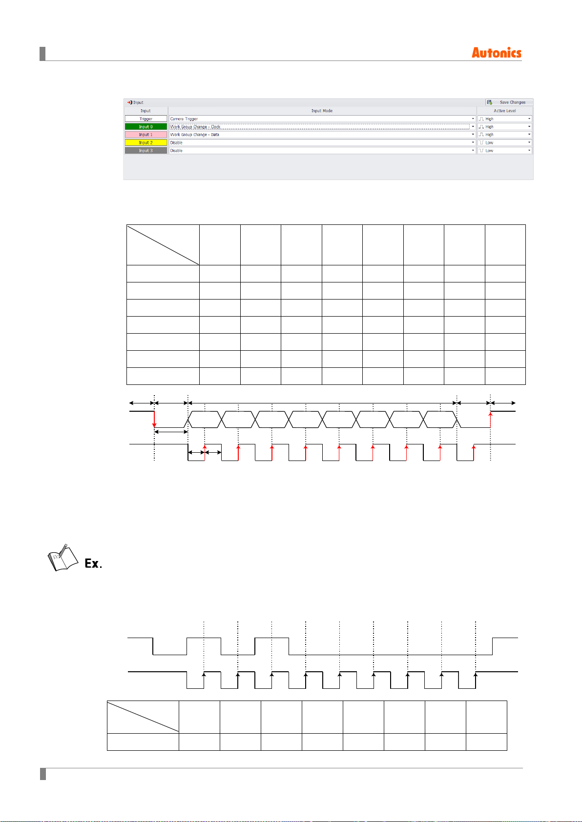
- Serial input (IN0, IN1): Input 0 and input 1 are set to work group change – Clock or
work group change – Data, and work group is changed according to the serial input.
- Parallel input (IN0 to IN3): From input 0 to input 3 are set to each of work group
change bit 0 to 3, and work group is changed according to the parallel input.
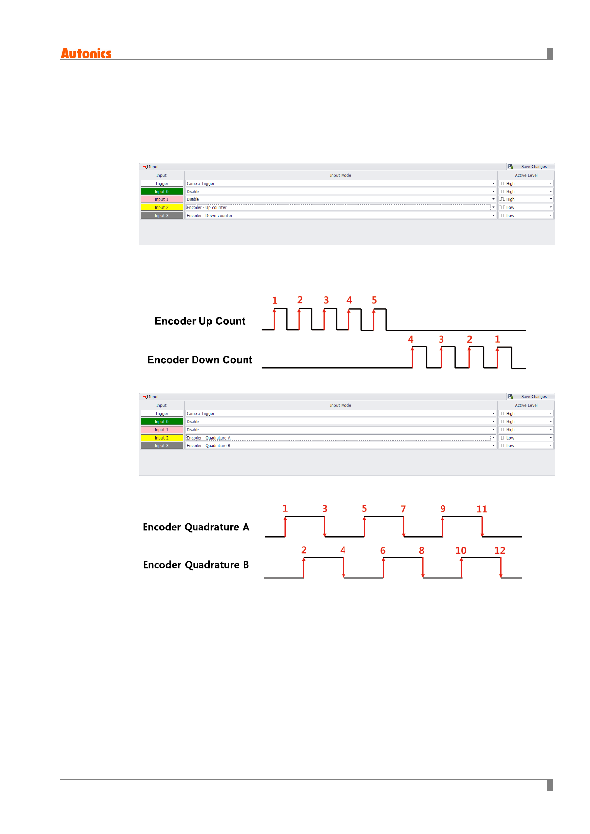
Encoder input (IN2, IN3): After input of trigger signal, the vision sensor takes image
after waiting for a while according to the number of encoder pulse. The types of
encoder input consist of Up counter/Down counter, and Quadrature. Encoder input is
used for the trigger delay mode. Maximum 100kHz input can be recognized.
(2) Active level
According to the active level, trigger is applied at High or Low. To avoid chattering of trigger
signal, the vision sensor starts taking an image when the signal is maintained for 1ms.
66 © Copyright Reserved Autonics Co., Ltd.
Page 67
6.6.3.1 Input mode
Input
Signal
Function
6 Vision Sensor Program [Vision Master]
0 IN0
1 IN1
2 IN2
3 IN3
Work group change
Bit 0
Work group change
Bit 1
Work group change
Bit 2
Work group change
Bit 3
Work group change
- Clock
Work group change
- Data
Encoder - Up counter
- Quadrature A
Encoder - Down counter
- Quadrature B
(1) Work group change – parallel input (IN0 to IN3)
According to the parallel input, work group is changed.
With parallel input, work group from 1 to 16 can be changed to.
(Following table is based on the High active level.)
Input
Work group
Bit 3 (IN3) Bit 2(IN2) Bit 1(IN1) Bit 0(IN0)
Alarm cleared
Work group 1 Low Low Low Low
Work group 2 Low Low Low High
Work group 3 Low Low High Low
Work group 4 Low Low High High
Work group 5 Low High Low Low
Work group 6 Low High Low High
Work group 7 Low High High Low
Work group 8 Low High High High
… … … … …
Work group 16 High High High High
© Copyright Reserved Autonics Co., Ltd. 67
Page 68
6 Vision Sensor Program [Vision Master]
Data
Cloc k
Bit0 Bit1 Bit2 Bit3 Bit4 Bit5 Bit6 Bit7
Wai t Star t Data
10ms
10ms
20ms
End W ai t
Data
Cloc k
1 0 1 0 0 0 0 0
(2) Work group change – serial input (IN0, IN1)
According to the serial input, work group is changed.
Although data is 8-bit, 5 less significant bits are used, because the maximum number of
work group is 32.
With serial input, work group from 1 to 32 can be changed to.
Input
Bit 0 Bit 1 Bit 2 Bit 3 Bit 4 Bit 5 Bit 6 Bit 7
Work group
Work group 1 0 0 0 0 0 0 0 0
Work group 2 1 0 0 0 0 0 0 0
Work group 3 0 1 0 0 0 0 0 0
Work group 4 1 1 0 0 0 0 0 0
Work group 5 0 0 1 0 0 0 0 0
… … … … … … … … …
Work group 32 1 1 1 1 1 0 0 0
- Start bit: Start bit holds the data signal at Low (Falling edge) for 20ms.
- Clock bit: Clock bit is pulse of 20ms interval which acquires data at the Rising edge.
- Data bit: Data bit is synchronized with Falling edge of the clock signal and holds Low or
High for 20ms.
- End bit: After 8
When changing work group of the vision sensor to work group 6 with the serial input signal, input
the data signal as follows.
Input
Work group
68 © Copyright Reserved Autonics Co., Ltd.
Work group 6 1 0 1 0 0 0 0 0
th
data, end bit holds the data signal for 20ms.
Bit 0 Bit 1 Bit 2 Bit 3 Bit 4 Bit 5 Bit 6 Bit 7
Page 69
6 Vision Sensor Program [Vision Master]
(3) Encoder input
You can use encoder input when you want to use the trigger delay mode of external trigger
input on encoder pulse.
Camera trigger occurs after calculating moving distance according to the number of input
pulse.
Up counter/Down counter (IN2, IN3)
Input 2 and input 3 are used as each of encoder input up counter and down counter.
The number of pulse is counted up or down according to the active level. If you use only one
encoder input, connect unusing input terminal to COMMON. Rising edge is counted in the
high active level, and falling edge is counted in the low active level.
Quadrature A/Quadrature B (IN2, IN3)
Input 2 and input 3 are operated in encoder Quadrature. Both rising edge and falling edge of
two encoders are counted.
© Copyright Reserved Autonics Co., Ltd. 69
Page 70
6 Vision Sensor Program [Vision Master]
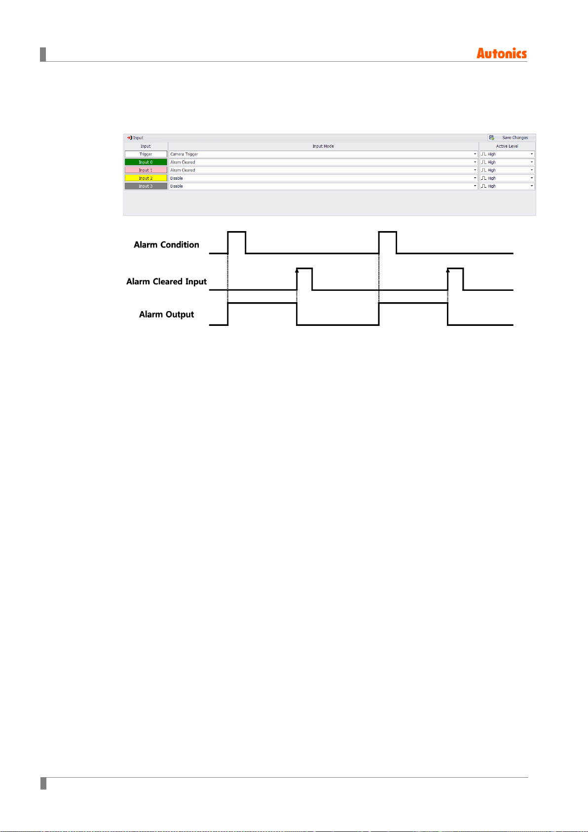
(4) Alarm cleared
You can use the alarm cleared input to cleare alarm which is set in the output menu, when
alarm is ON. Although alarm is cleared, alarm occures again in the status at alarm condition
which is set in the output menu,
70 © Copyright Reserved Autonics Co., Ltd.
Page 71
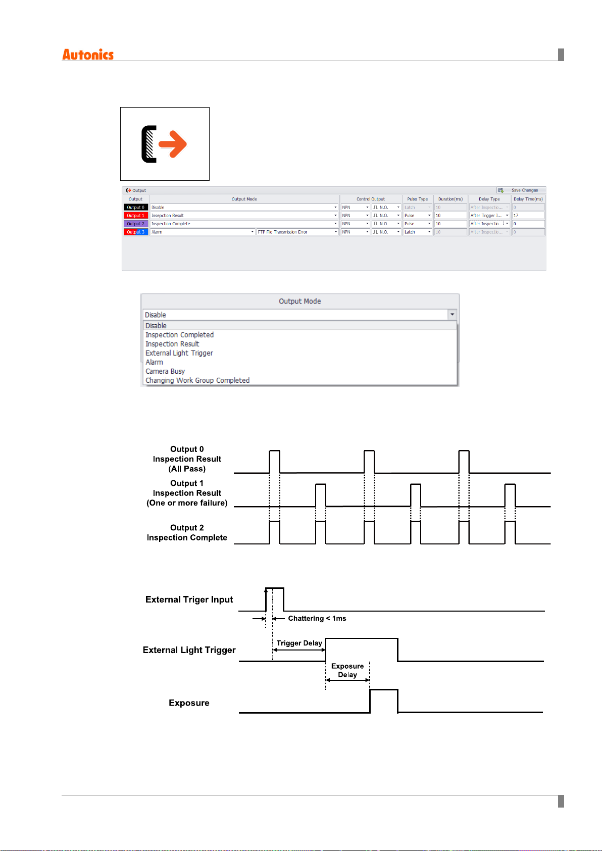
6.6.4 Output
(1) Output mode
6 Vision Sensor Program [Vision Master]
Inspection Complete: Regardless of the inspection result, the vision sensor outputs
output signal at the moment of inspection completion.
Inspection Result: According to the settings of Output Inspection Result Selection, the
vision sensor outputs output signal. Please refer to '6.6.5 Work Group'.
External light trigger: When connected with the external light, power of the external light
is turned ON/OFF with output signal from the vision sensor which is synchronized with
camera trigger input.
© Copyright Reserved Autonics Co., Ltd. 71
Page 72
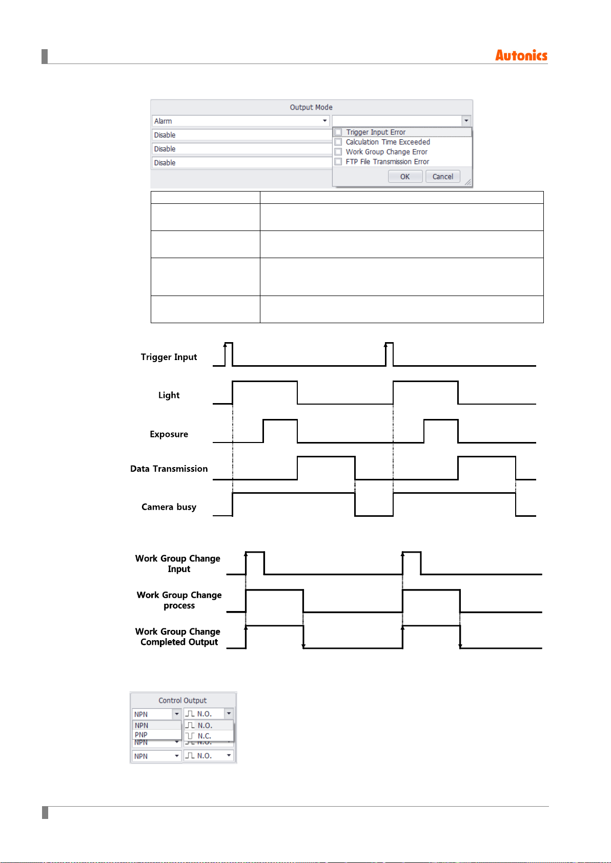
6 Vision Sensor Program [Vision Master]
Alarm output
Description
Alarm: In occurrence of vision sensor error, the vision sensor outputs output signal.
Trigger input error
Operating time
exceeded
Work group change
error
FTP file transmission
error
When trigger is input in high camera busy signal, the vision
sensor outputs alarm.
When operating time of work group is exceeded set inspection
time, the vision sensor outputs alarm.
When unregistered work group number is entered or wrong
Clock or Data is input in serial or parallel input, the vision
sensor output alarm.
When FTP access error or FTP transmission error in saving
inspection result occurs, the vision sensor outputs alarm.
Camera busy: It is operating status of the camera, after camera trigger input.
Changing work group completed: It is signal to notice that changing work group is
completed after inputting work group change input.
(2) Control output
You can set control output to NPN/PNP and N.O.(Normally open) / N.C(Normally close).
72 © Copyright Reserved Autonics Co., Ltd.
Page 73
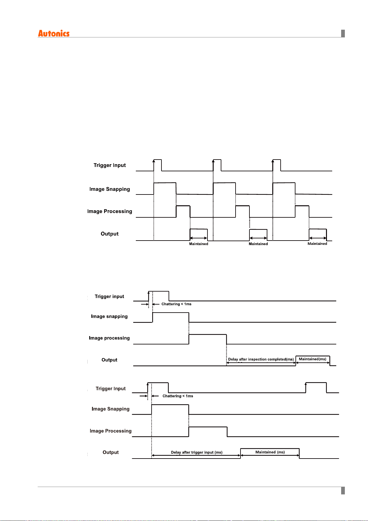
6 Vision Sensor Program [Vision Master]
(3) Pulse type
You can select pulse type for output.
You can select pulse type only when the output mode is set to ‘Inspection complete’,
‘Inspection result’, or ‘Alarm’.
Pulse: Output signal is output during set output duration.
Latch: Output signal is kept outputting before next output signal.
(4) Duration
Duration is the time period of maintaining inspection result output signal for.
You can set duration by setting output mode to “Inspection result” and pulse type to “Pulse”.
Setting range is from 1 to 60,000ms.
Timing diagram of output duration (ms).
(5) Delay type
Delay type is the moment of applying output delay time to. You can set whether to delay
output after inspection completed or to delay output after trigger input.
Delay output after inspection completed
Delay output after trigger input
© Copyright Reserved Autonics Co., Ltd. 73
Page 74

6 Vision Sensor Program [Vision Master]
(6) Delay time
Delay time is the time period of delaying inspection result output for, after starting of output
delay operation.
Setting range when delay type is “After inspection completed”: 0 to 60,000ms
Setting range when delay type is “After trigger input”: 17 to 60,000ms
74 © Copyright Reserved Autonics Co., Ltd.
Page 75
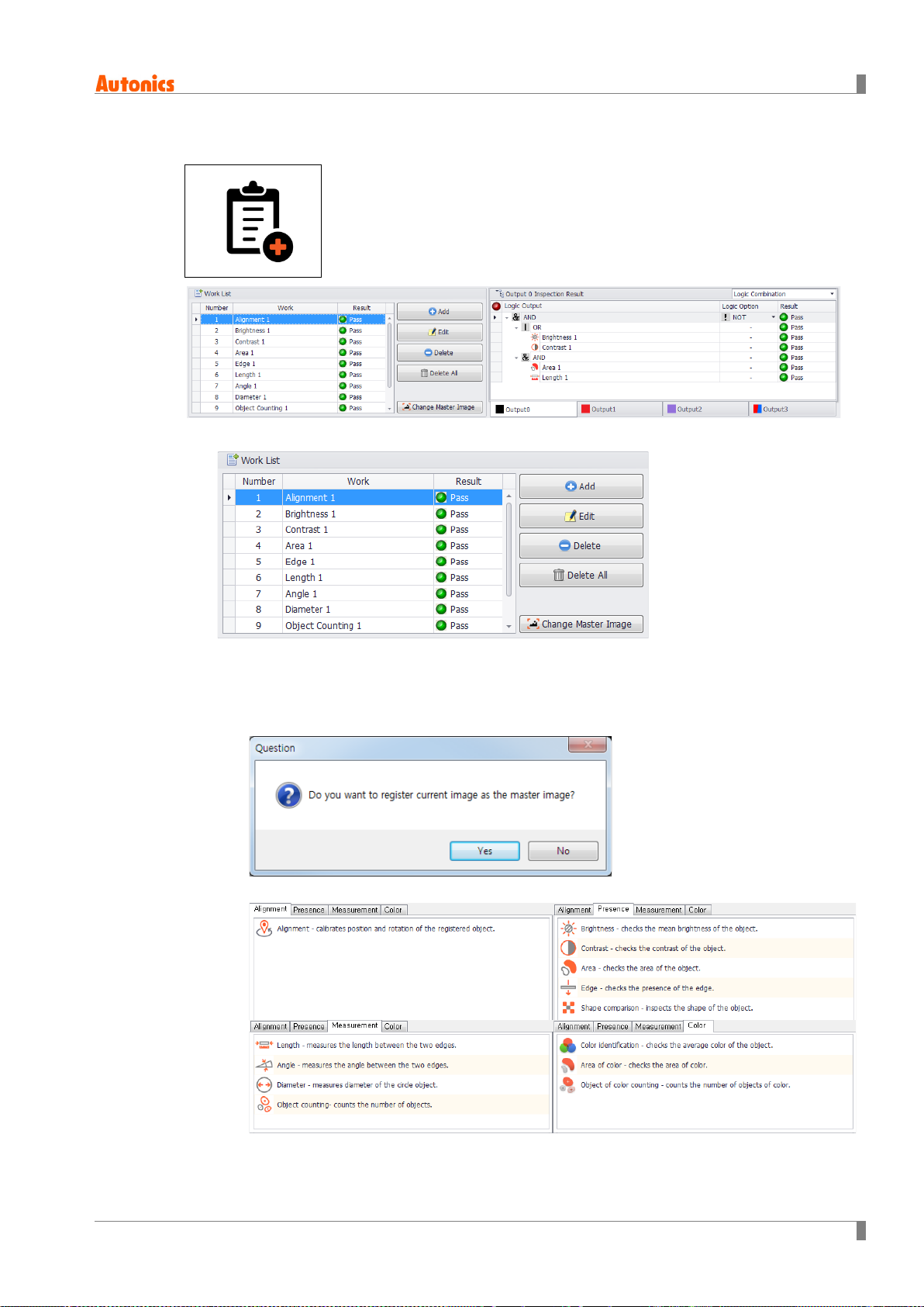
6.6.5 Work Group
(1) Work list
6 Vision Sensor Program [Vision Master]
Work list displays a list of the currently registered works and you can register work to
inspect and edit or delete the registered works in Work list.
Add: You can register work to inspect. Select inspection type and register.
When making new work group and adding work, an image in the image window is
registered ads master image.
Please refer to '6.7 Inspection ' for inspection item setting.
© Copyright Reserved Autonics Co., Ltd. 75
Page 76
6 Vision Sensor Program [Vision Master]
Edit: Select the registered work in the list and click Edit to edit the work.
Delete / Delete All: Select the registered work in the list and delete a work or delete all
works.
Change master image: You can change image template of the work to register. The currently
displayed image in the image window is registered as master image.
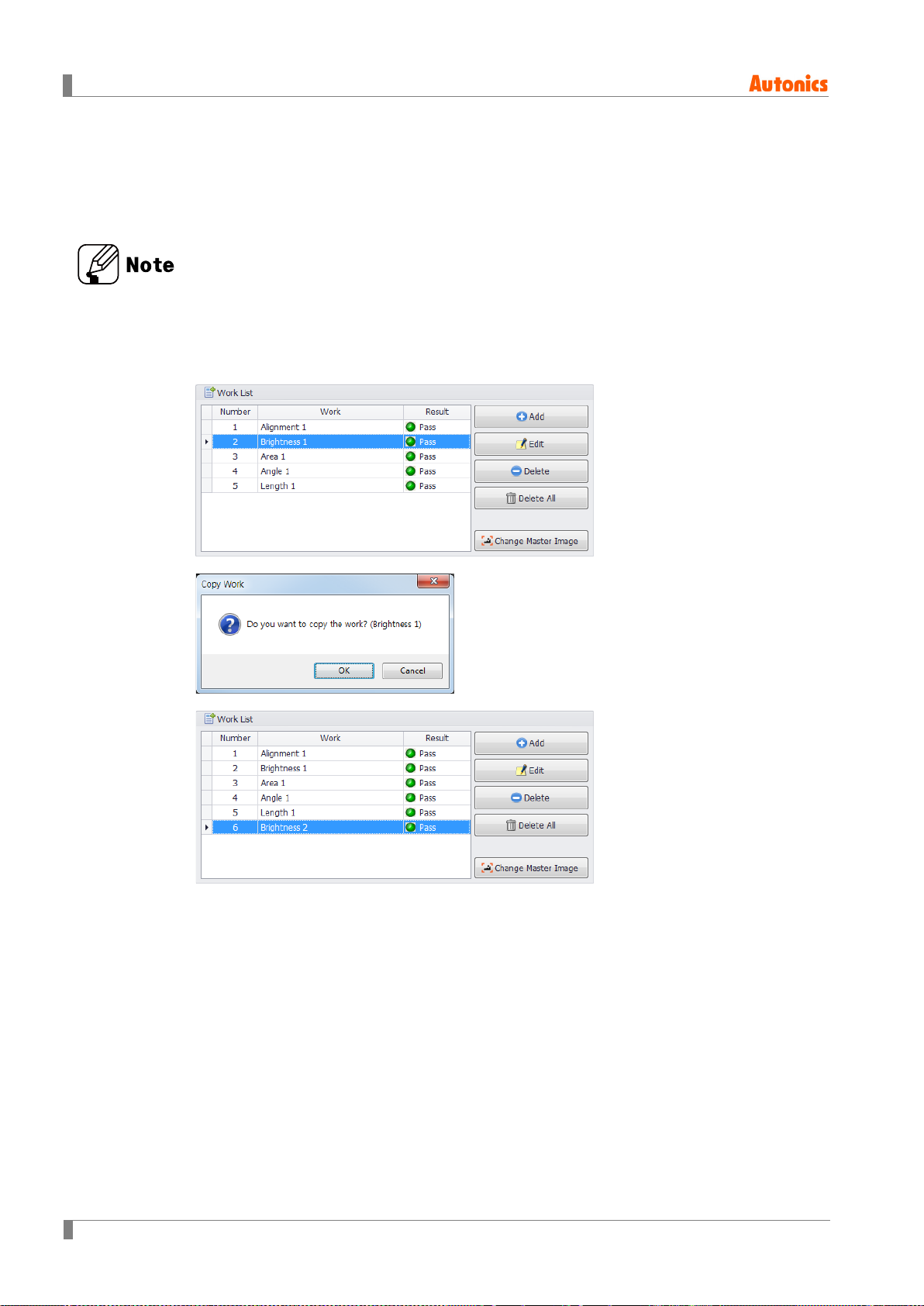
You can copy and paste registered works in the work list by using Ctrl+C and Ct rl +V.
It is except for Alignment 1 work.
1st Select a work to copy, and press Ctrl+C key to copy.
e.g.) Brightness 1
2nd Press Ctrl+V key to open the message pop-up as below, and click ‘OK’.
3rd The work is copied.
4th Select the copy of the work and click ‘Edit’ to change specific settings of the work.
76 © Copyright Reserved Autonics Co., Ltd.
Page 77
6 Vision Sensor Program [Vision Master]
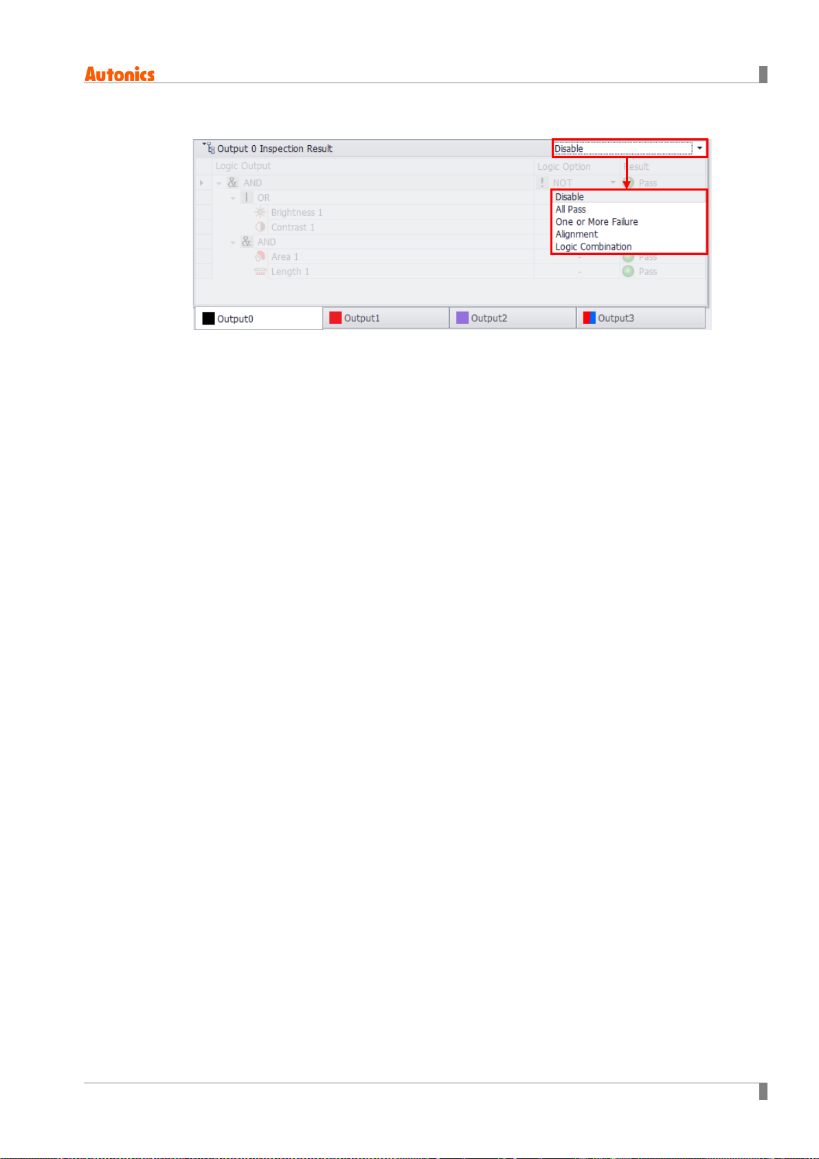
(2) Output inspection result selection
Set output mode in output menu to “inspection result” and set outputting condition among
followings.
Disable
All pass: When all of inspection results are passed, the vision sensor outputs output
signal.
One or more failure: When one or more inspection result is failed to pass, the vision
sensor outputs output signal.
Alignment: When inspection items with alignment are passed, the vision sensor outputs
output signal.
Logic combination: You can set output conditions by setting each logic combination to
pass or fail with logical operator.
© Copyright Reserved Autonics Co., Ltd. 77
Page 78
6 Vision Sensor Program [Vision Master]
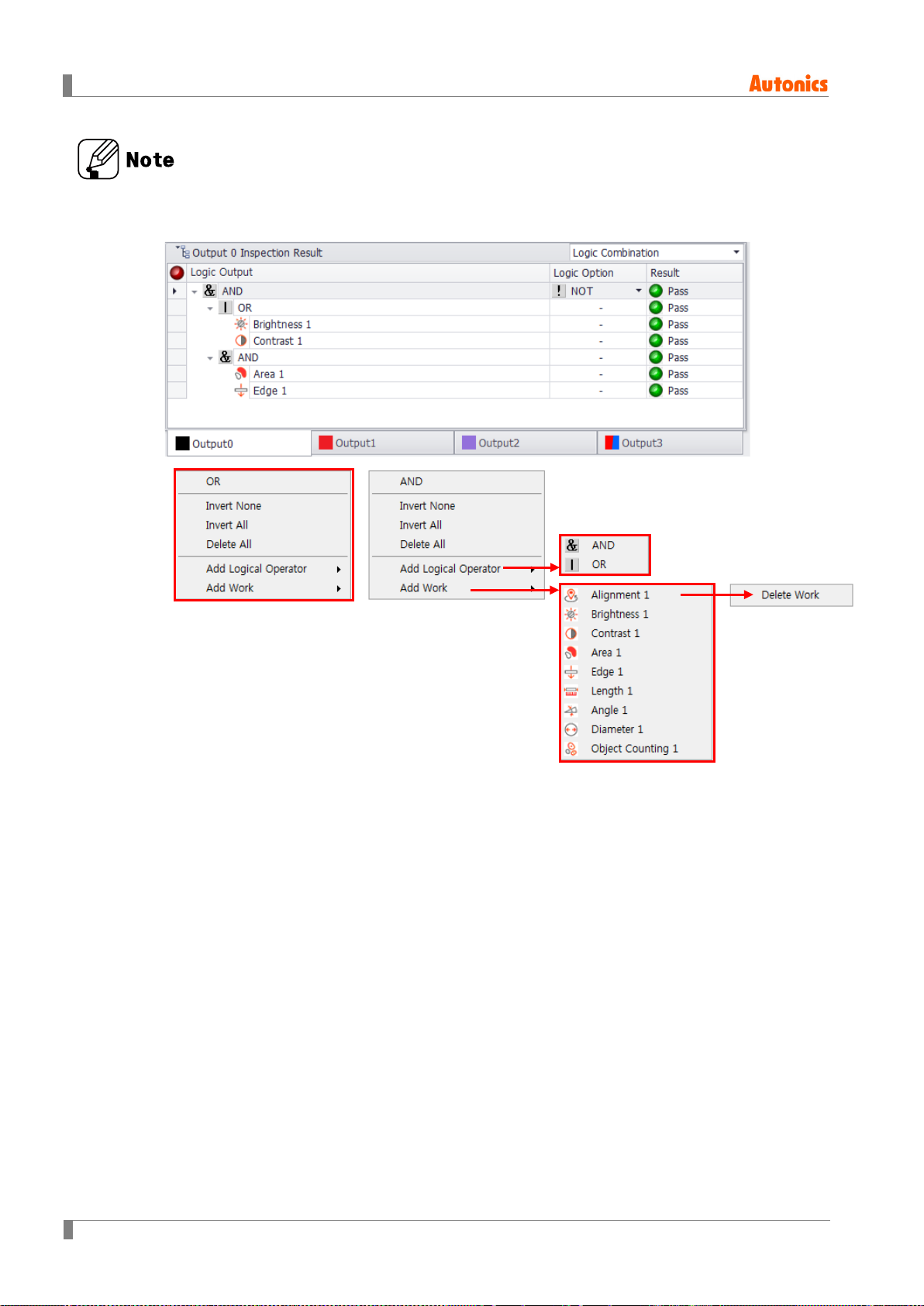
When setting output with logic combination, set output condition using logical operator for each
output.
AND/OR: You can select logic operator.
Invert none: You can set logical option of all work to NONE(-).
Invert all: You can set logical option of all work to NOT.
Delete all/Delete logical operator: You can delete all registered settings of with Delete all
and registered logic operator with Delete logical operator.
Add logical operator: You can add logical operator (AND/OR).
Add work/Delete work: You can add registered work to logical output or delete work from
logical output.
78 © Copyright Reserved Autonics Co., Ltd.
Page 79
6.6.6 Inspection
No.
Item
Description
(1) Device
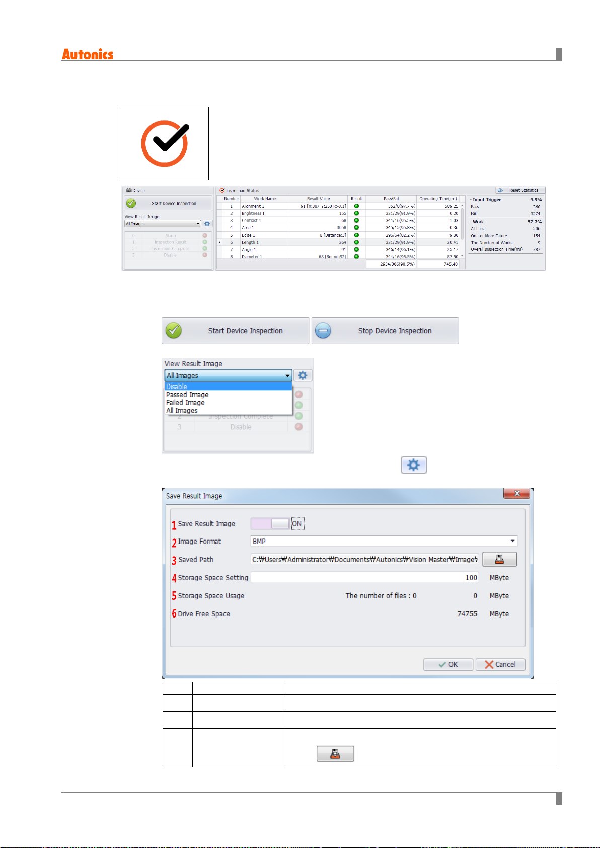
Start/Stop device inspection: You can activate vision sensor in operation mode and start
inspection in registered work group.
View result image: Yo u can set image to display in the image window during inspection.
6 Vision Sensor Program [Vision Master]
Save result image: Click the ‘Save result image’ icon ( ) on the right side in View
result image. You can set the result image in local disk of the PC.
1 Save result image Sets whether to save inspection result image.
2 Image format Selects image format to save in. (BMP, PNG, JPG)
Selects saved path in which result images are saved.
3 Saved path
Click on the right to select saved path.
© Copyright Reserved Autonics Co., Ltd. 79
Page 80
6 Vision Sensor Program [Vision Master]
No.
Item
Description
Storage space
4
setting
Storage space
5
usage
6 Drive free space Displays drive free space of the PC.
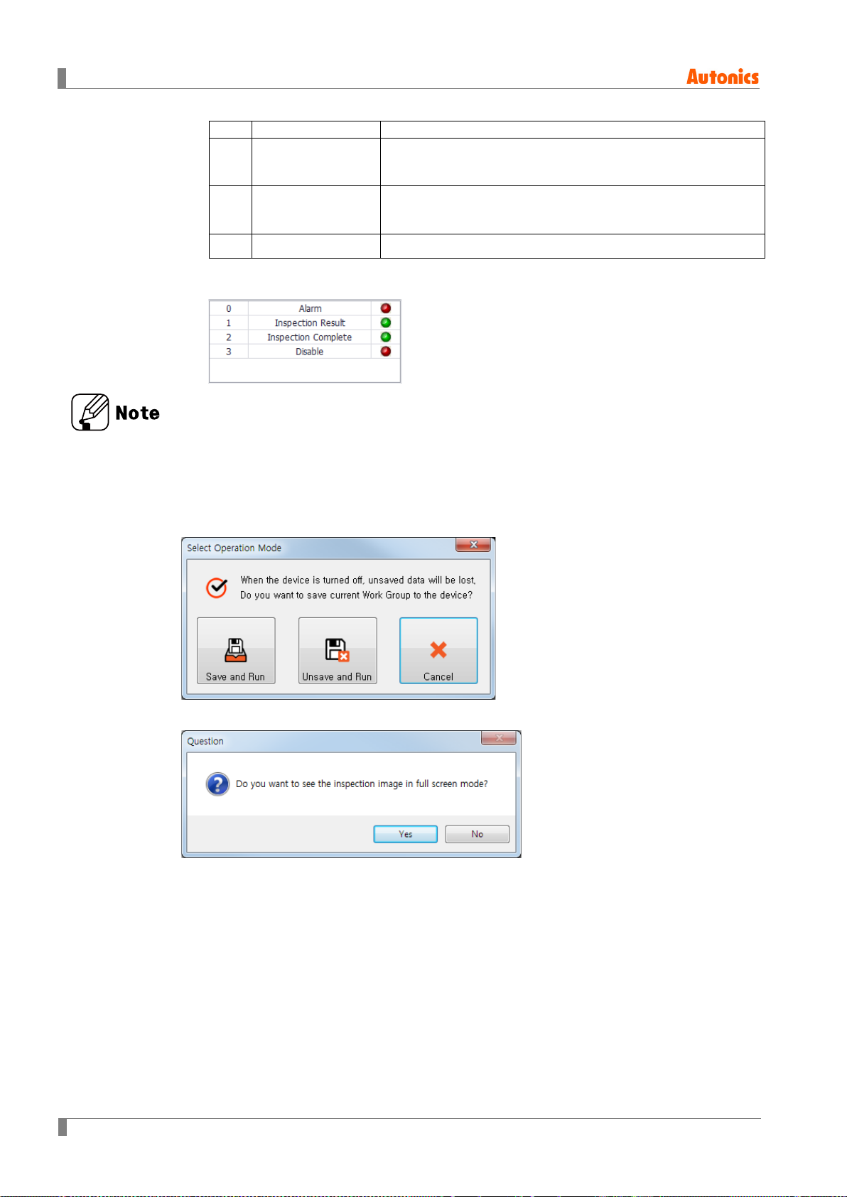
Output status: Output status displays output status during inspection. You can check
output mode and operation status of output.
Checks drive free space and allocates space to save.
Displays the number and volume of the files in storage space.
Please refer to followings when clicking Start device inspection to activate operation mode.
Select operation mode: It is to set operation when starting inspection. You can select
whether to save or not to save before starting inspection. When the device is turned off, you
can lose unsaved data.
Setting of displaying the inspection image in full screen
80 © Copyright Reserved Autonics Co., Ltd.
Page 81
6 Vision Sensor Program [Vision Master]
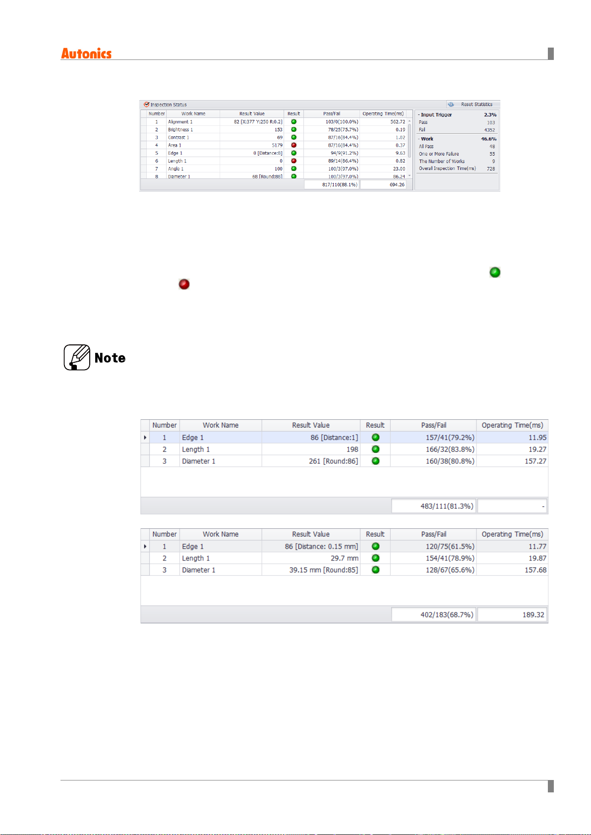
(2) Inspection Status
Work name: Displays work name of inspection items.
Result value: Displays measured result value of each work ROI.
Result: Displays pass/fail for inspection result.
Pass/Fail: Displays counting of the number of pass/fail and pass rate.
Operation time: Displays operation time of each inspection item.
Reset statistics: Resets all statistics about inspection result including pass ( ) /
fail ( ) status and operation time.
Input trigger: Displays statistics of input trigger. It helps you to check input is operating
in normal status by counting the number of pass/fail status of input trigger.
Work: Displays statistics of work. It displays the number of inspection result of All pass,
One or more failure, the number of total work, and inspection time.
When operating device inspection with calibration function, result value of the ‘edge’, ‘length’,
and ‘diameter’ inspections are displayed as actual value in the unit of mm, not pixel.
Inspection result value without calibration function
Inspection result value with calibration function
© Copyright Reserved Autonics Co., Ltd. 81
Page 82
6 Vision Sensor Program [Vision Master]
Icon
Function
Description
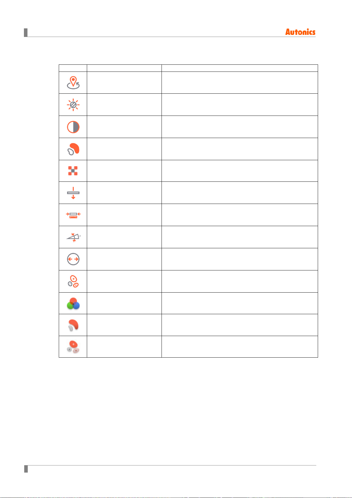
6.7 Inspection
Alignment
Brightness To inspect average brightness of the target
Contrast To inspect average contrast of the target
Area To inspect area of the target
Shape comparison To inpect shape of the target
Edge To inspect the presence of the edge
Length To inspect the length between two edges
Angle To inspect the angle between two edges
To align position and orientation of the target based on
the registered target
Diameter To inspect diameter of the circle
Object counting To count the number of the object
Color identification To inspect average color of the object
Area of color To inspect area in a certain color
Object of color counting To count the number of objects in a certain color
82 © Copyright Reserved Autonics Co., Ltd.
Page 83
6.7.1 Alignment
No.
item
Description
in it.
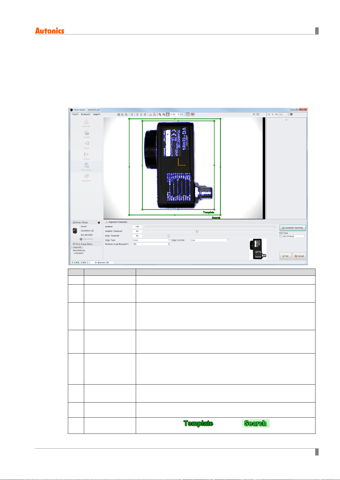
You can use the alignment function to align position and orientation of the target based on the
registered target.
Alignment compares features of the registered target and features of the input image to figure
out location of similar pattern, and then inspects the input image based on location and rotation
angle of the target. It is used to check the presence of inspection target to rotate, to inspect
pattern, or to align position of the target.
6 Vision Sensor Program [Vision Master]
1 Similarity It is the similarity between registered template and detected template.
Similarity
2
threshold
3 Edge threshold
4 Edge type
5 Edge contrast
Rotation angle
6
range (±°)
Automatic
7
teaching
8 ROI type
※1
It is discrimination value of the similarity for deciding pass/fail.
It is threshold to detect edge.
Only edges with high contrast can be detected in high edge threshold,
while edges with low contrast also can be detected in low edge
threshold.
It limits amount of information according to the edge direction.
- Curve: It leads pixels from all edges.
- Straight: It leads pixels only from straight edge.
It limits amount of edge information according to the contrast value.
- High: It uses edges of high contrast.
- Medium: It uses edges of high and medium contrast.
- Low: It uses edges of high, medium, and low contrast.
It limits detecting area to the set angle range, by setting angle range of
the rotated image to detect.
It operates teaching automatically, when user changes parameter or
adjust ROI.
After setting ROI ( ), set area ( ) to inspect ROI
© Copyright Reserved Autonics Co., Ltd. 83
Page 84
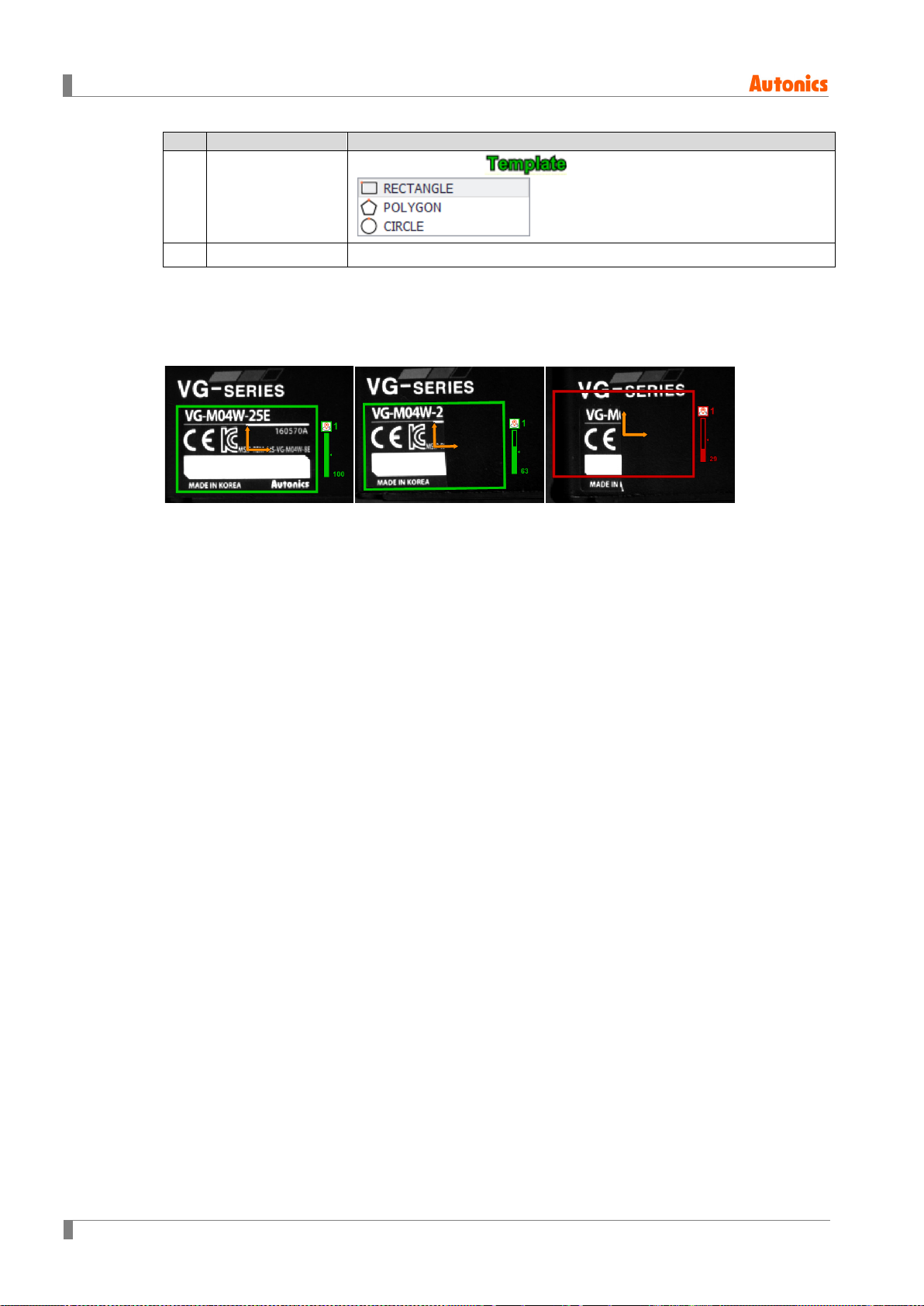
6 Vision Sensor Program [Vision Master]
No.
item
Description
It sets type of ROI ( ) to inspect.
(rectangle/polygon/circle)
9 OK/Cancel It registers work to work group or cancel to register.
※Threshold is the boundary value when a value is discontinuously changed.
※1. When set template of ROI is 50% similar with the input image in 50 similarity threshold, the
vision sensor regards them as the same target and outputs output signal.
84 © Copyright Reserved Autonics Co., Ltd.
Page 85
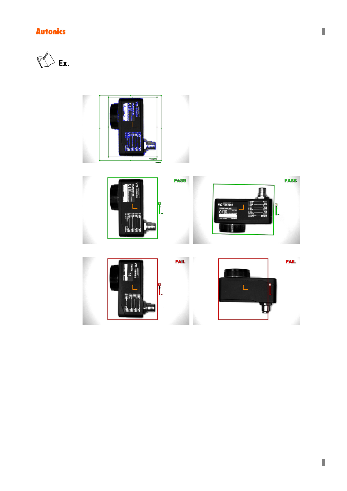
6 Vision Sensor Program [Vision Master]
Examples of pass/fail in the alignment inspection
Registering template of inspection target (similarity: 100% / similarity threshold: 80%)
Passed alignment inspection.
Failed alignment inspection.
© Copyright Reserved Autonics Co., Ltd. 85
Page 86
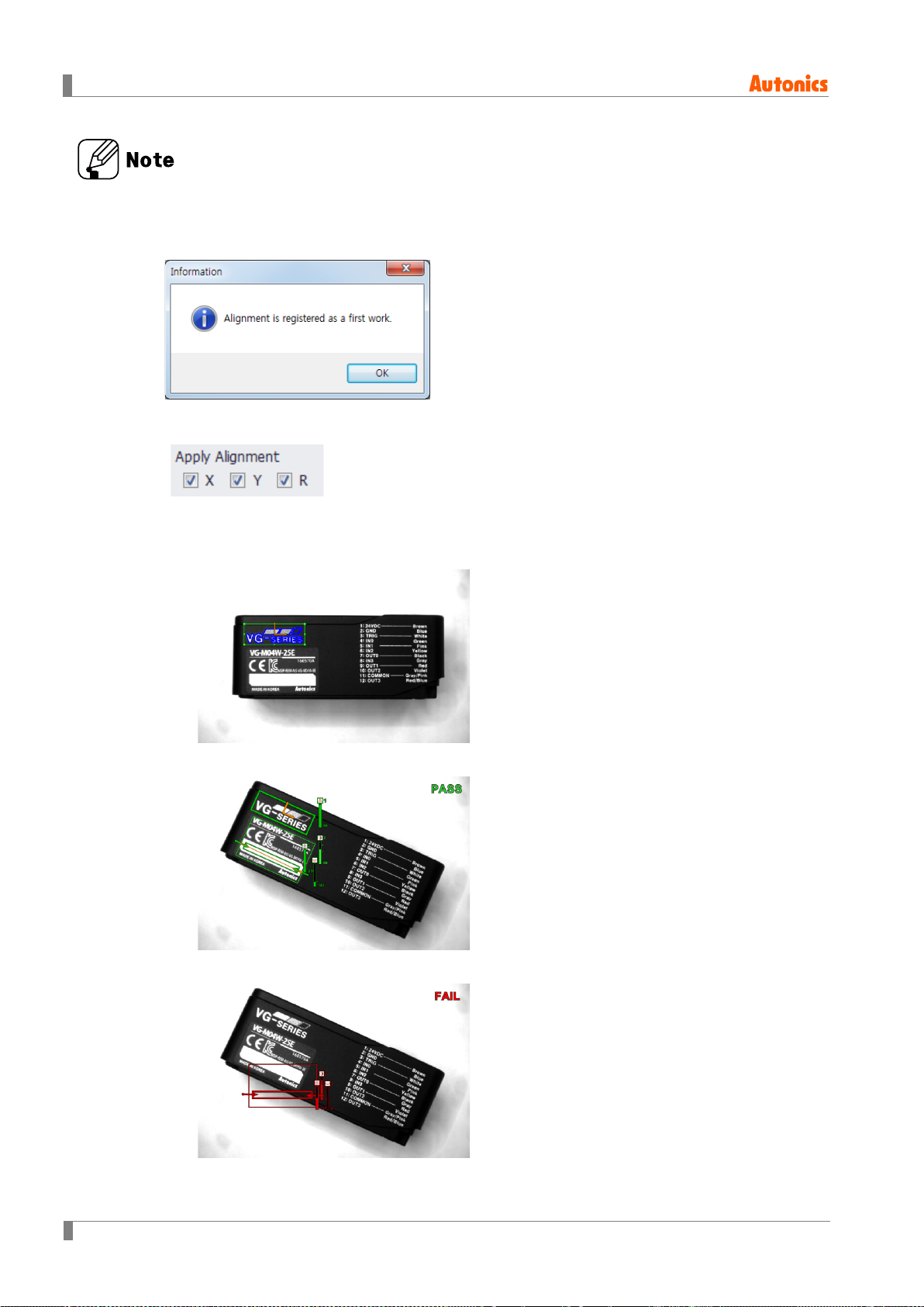
6 Vision Sensor Program [Vision Master]
When inspecting inspection items including alignment, alignment is prior to any other inspection
items, so that rotating inspection target by alignment also rotates position of other inspection
items.
If you want to apply alignment to each inspection, check ‘Apply alignment’ in the right bottom.
X: moving X axis coordinate / Y: moving Y axis coordinate / R: angle
Examples of pass/fail when inspecting multiple work including alignment
Registering template of the inspection target (registering alignment)
Applying alignment
Unapplying alignment
86 © Copyright Reserved Autonics Co., Ltd.
Page 87
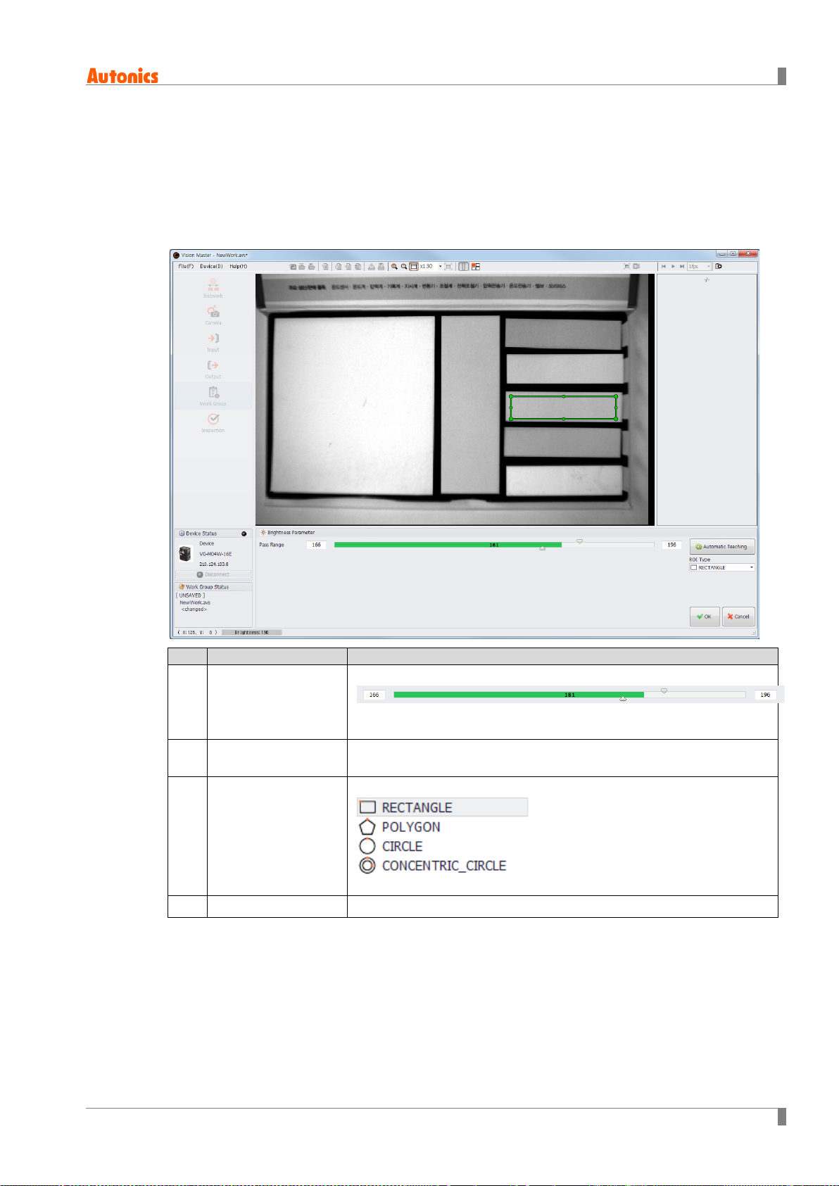
6.7.2 Brightness
No.
Item
Description
You can use the brightness function to inspect average brightness of the target.
Brightness compares mean brightness of the registered ROI and that of input image ROI. It sets
pass range based on the mean brightness value of the registered ROI. The mean brightness
value of the inspection target within the pass range is regarded as Pass, while the mean
brightness value of the inspection target out of the pass range is regarded as Fail.
6 Vision Sensor Program [Vision Master]
It sets the pass/fail range of brightness.
1 Pass range
2 Automatic teaching
3 ROI type
4 OK/Cancel It registers work to work group or cancel to register.
Lower limit ROI mean Upper limit
for pass brightness value for pass
Even if user set the pass range, it teaches pass range based on mean
brightness of ROI.
It sets type of ROI to inspect.
(rectangle/polygon/circle/concentric circle)
© Copyright Reserved Autonics Co., Ltd. 87
Page 88
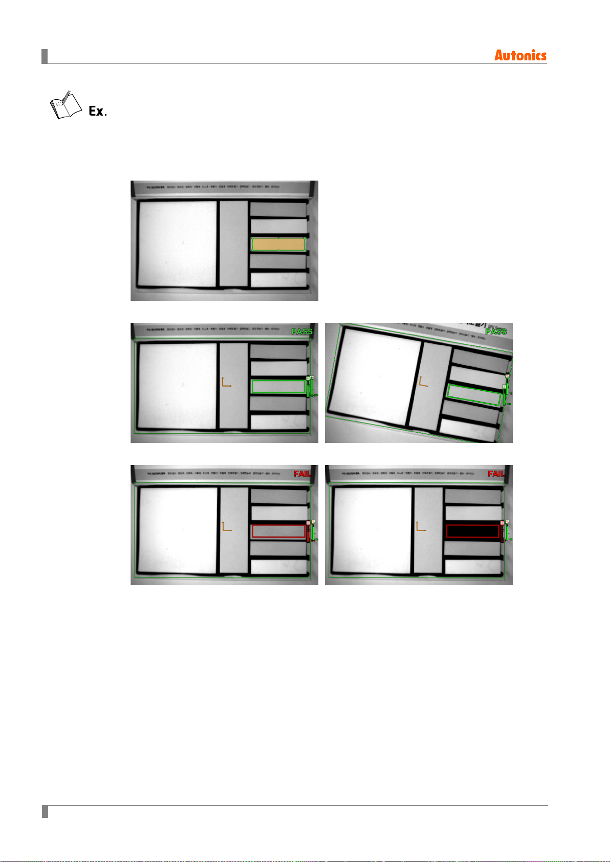
6 Vision Sensor Program [Vision Master]
Examples of pass/fail in the brightness inspection
Registering template of the inspection target
(mean brightness: 181 / pass range: 166 to 196)
Passed brightness (alignment applied)
Failed brightness
(Reduced ROI area brightness) (Below mean brightness of ROI area)
88 © Copyright Reserved Autonics Co., Ltd.
Page 89
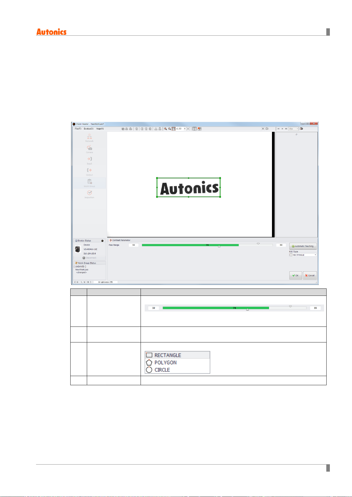
6.7.3 Contrast
No.
Item
Description
You can use contrast function to inspect average contrast of the target.
Contrast is amount of gap between bright part and dark part in the image.
Contrast compares registered ROI contrast and ROI contrast of the input image to figure out
changes in contrast. It sets pass range based on the registered contrast value of ROI. The
contrast value of the inspection target within the pass range is regarded as Pass, while the
contrast value of the inspection target out of the pass range is regarded as Fail. The contrast
value is displayed in the percentage.
6 Vision Sensor Program [Vision Master]
It sets the pass/fail range of contrast.
2 Pass range
Automatic
3
teaching
4 ROI type
5 OK/Cancel It registers work to work group or cancel to register.
Lower limit ROI Upper limit
for pass average contrast for pass
Even if user set the pass range, it teaches pass range based on the
average contrast value of ROI.
It sets type of ROI to inspect.
(rectangle/polygon/circle)
© Copyright Reserved Autonics Co., Ltd. 89
Page 90
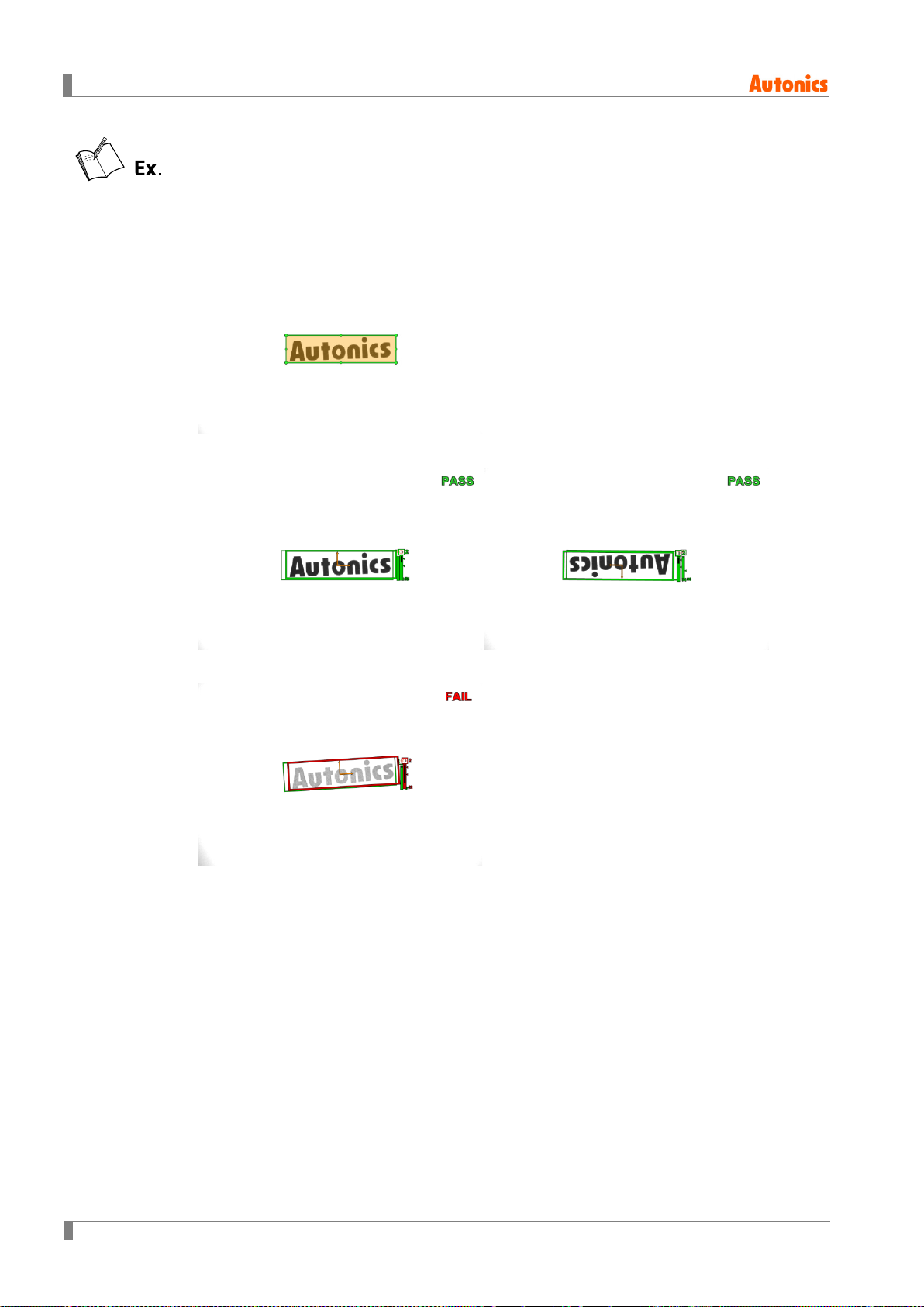
6 Vision Sensor Program [Vision Master]
Examples of pass/fail in the contrast inspection
Registering template of the inspection target (contrast: 74 / pass range: 59 to 89)
Passed contrast (alignment applied)
Failed contrast
90 © Copyright Reserved Autonics Co., Ltd.
Page 91
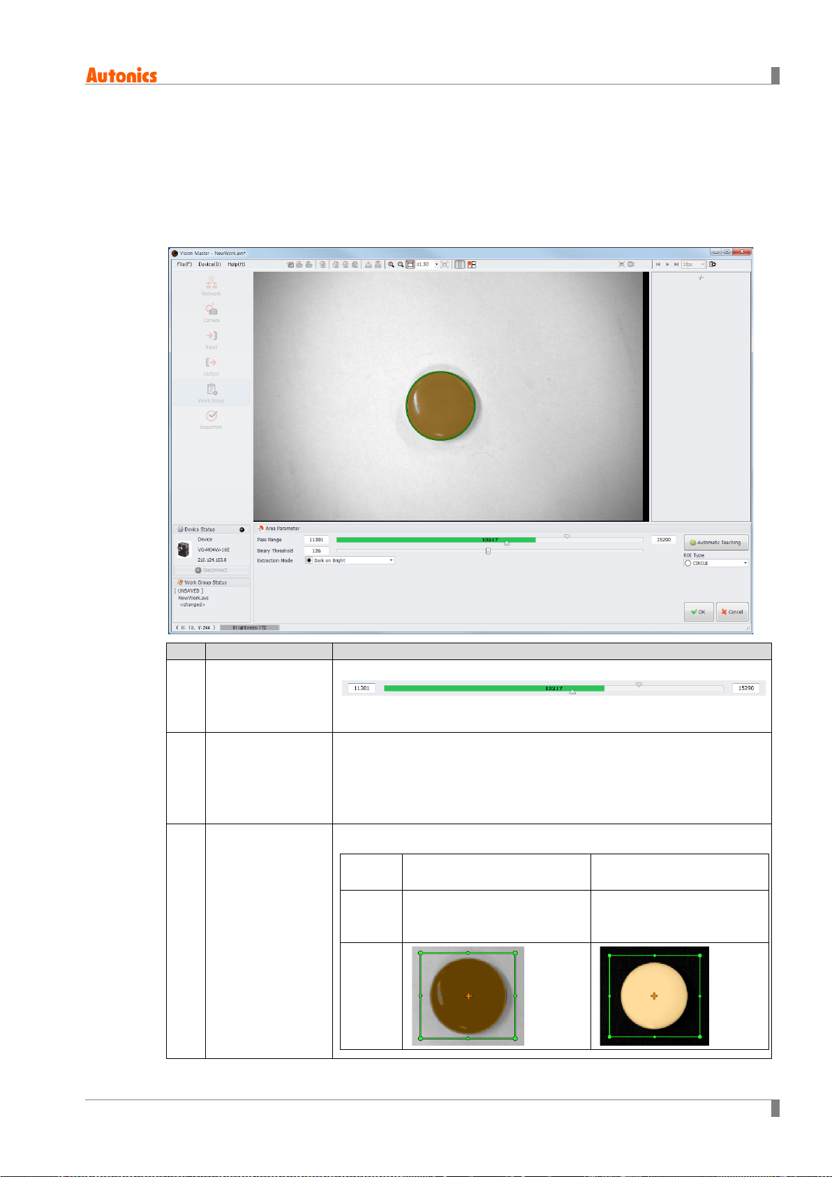
6.7.4 Area
No.
Item
Description
You can use the area function to inspect area of the target.
Area compares difference between registered ROI area and ROI area in the input image. It sets
the pass range based on the registered ROI area. The area of the inspection target within the
pass range is regarded as Pass, while the area of the inspection target without the pass range is
regarded as Fail.
6 Vision Sensor Program [Vision Master]
1 Pass range
2 Binary threshold
3 Extraction mode
It sets the pass/fail range of area.
Lower limit Measured ROI Upper limit
for pass area value for pass
It sets the threshold value to detect area.
It is to process inspection with the binary coded threshold value.
After converting each pixel of the image under the threshold value to 0
and each pixel of the image over the threshold value to 1, 0 passes the
area inspection, while 1 fails to pass the area inspection.
It sets method of detecting area.
Item
Descrip
tion
Dark object on the bright
background
Extracting darker area
compared to the brightness
standard
Bright object on the dark
background
Extracting brighter area
compared to the brightness
standard
Image
© Copyright Reserved Autonics Co., Ltd. 91
Page 92
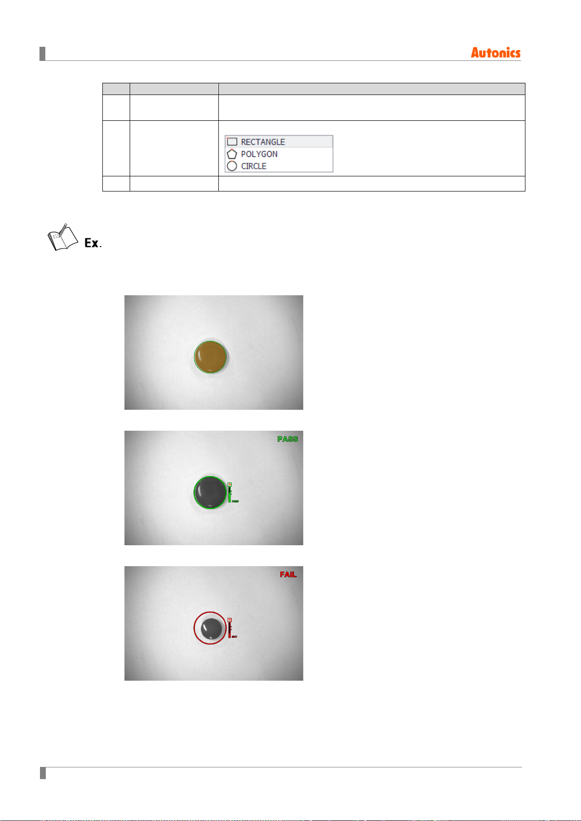
6 Vision Sensor Program [Vision Master]
No.
Item
Description
Automatic
4
teaching
5 ROI type
6 OK/Cancel It registers work to work group or cancel to register.
※Threshold is the boundary value when a value is discontinuously changed.
Even if user set the pass range, it teaches pass range based on the
pixel of ROI.
It sets type of ROI to inspect.
(rectangle/polygon/circle)
Examples of pass/fail in the area inspection
Registering template of the inspection target (area: 13229 / pass range: 11244 to 15213)
Passed area inspection
Failed area inspection
92 © Copyright Reserved Autonics Co., Ltd.
Page 93
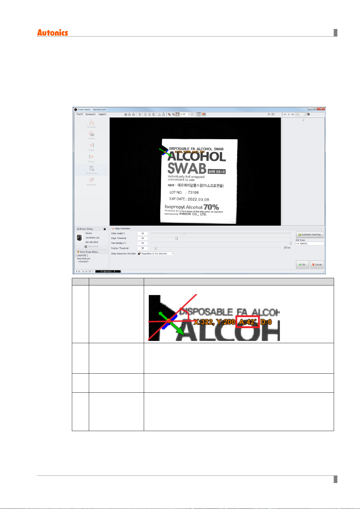
6.7.5 Edge
No.
Item
Description
You can use the edge function to inspect the presence of the edge.
Edge compares directions of the registered edge and edges in the same area of the input image
to detect the presence of the edge. It sets the pass range based on the direction of the
registered edge. The edge of the inspection target in the pass range is regarded as Pass, while
the edge of the inspection target out of the pass range is regarded as Fail.
6 Vision Sensor Program [Vision Master]
1
Edge angle(°)
2 Edge threshold
3
Pass range(±°)
4 Position threshold
It is the measured angle value of edge grade.
It sets threshold to detect edge.
Only edges with high contrast can be detected in high edge threshold,
while edges with low contrast also can be detected in low edge
threshold.
It sets the pass/fail range of edge.
Setting range: ±0 to ±10°
It is range of the distance between edge at ROI teaching and edge
detected from inspection target.
If the distance between edge at ROI teaching (0) and edge detected
from inspection target is within the range of position threshold, it is
processed as pass.
© Copyright Reserved Autonics Co., Ltd. 93
Page 94
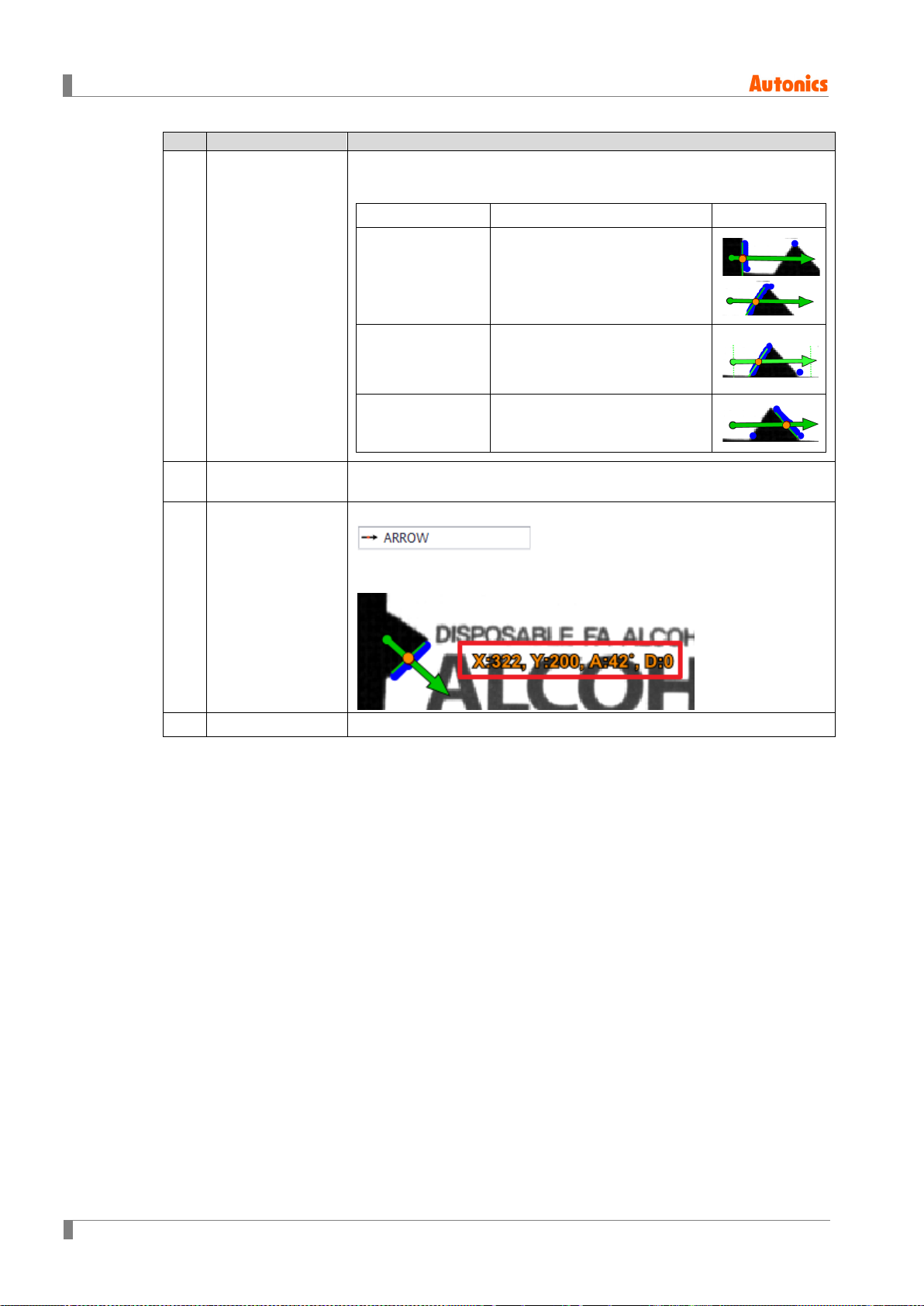
6 Vision Sensor Program [Vision Master]
No.
Item
Description
It sets method for inspecting edge.
It searches edge along the direction of arrow in the ROI.
Item Description Image
Edge Inspection
5
Direction
Regardless of the
direction
Bright area
→ Dark area
Detects firstly encountering
edge in the ROI range.
Detects edge on the boundary
line from bright area to dark
area.
Dark area
→ Bright area
Automatic
6
teaching
7 ROI type
8 OK/Cancel It registers work to work group or cancel to register.
When user changes parameter or adjust ROI, it teaches automatically.
It sets type of ROI to inspect.
X, Y axes coordinate of the edge (A) and distance from the edge (D) are
displayed.
Detects edge on the boundary
line from dark area to bright
area.
(arrow)
※Threshold is the boundary value when a value is discontinuously changed.
94 © Copyright Reserved Autonics Co., Ltd.
Page 95
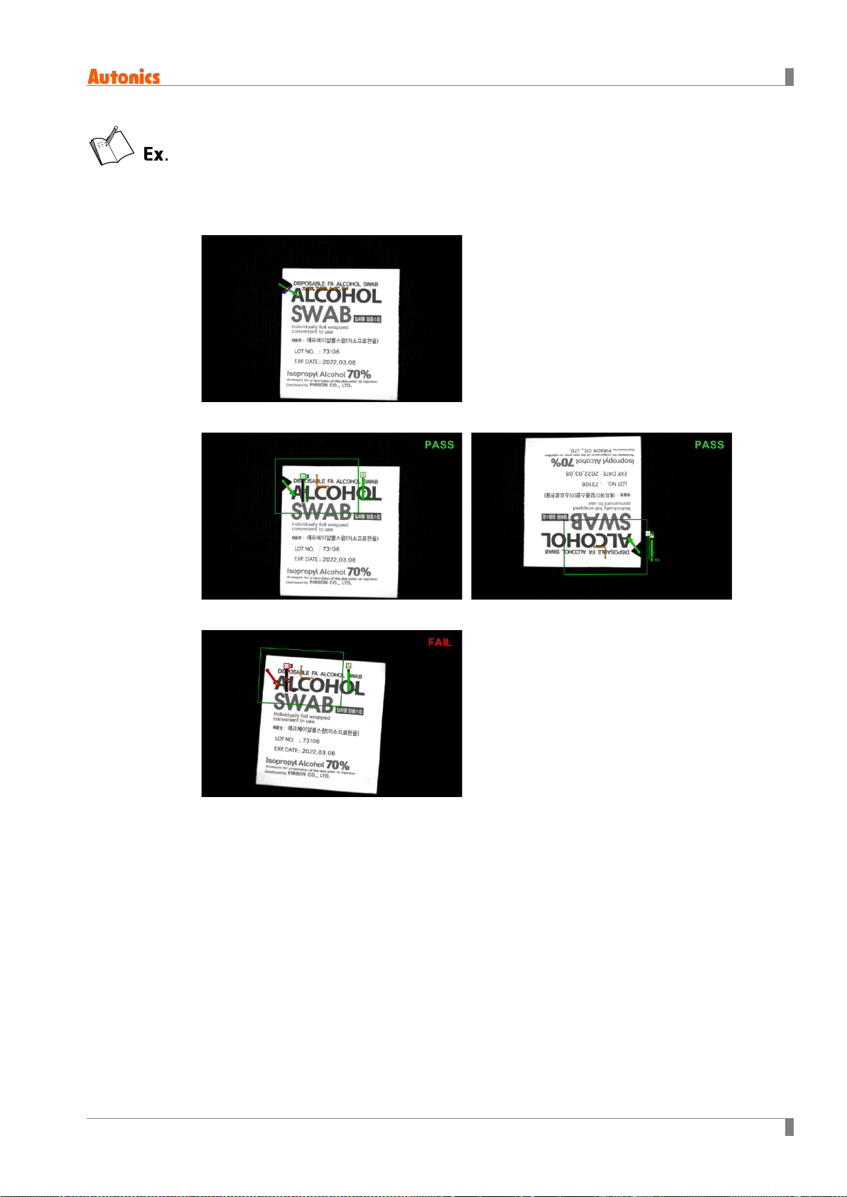
6 Vision Sensor Program [Vision Master]
Examples of pass/fail in the edge inspection
Registering template of the inspection target (edge angle: 42° / pass range: ±10°)
Passed edge (alignment applied)
Failed edge
© Copyright Reserved Autonics Co., Ltd. 95
Page 96
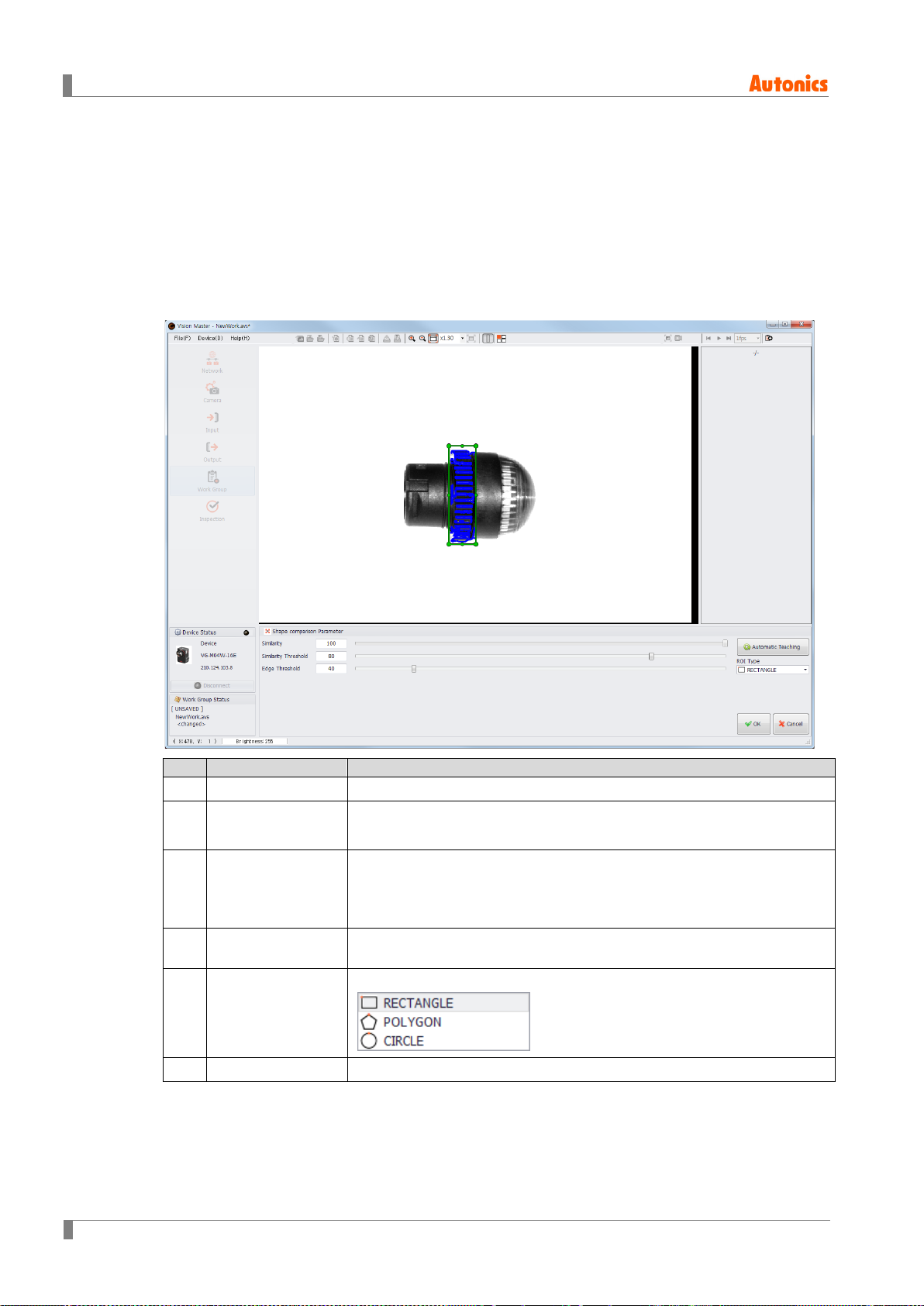
6 Vision Sensor Program [Vision Master]
No.
Item
Description
6.7.6 Shape comparison
You can use the shape comparison function to inspect the shape of the object.
Shape comparison compares features and patterns of the terget object in the ROI of the input
image and that of the registered image.
It sets pass range based on the similarity of the ROI in the registered image and the ROI in the
input image.
Similarity of the two images over the threshold is regarded as Pass, while similarity of the two
images under the threshold is regarded as Fail.
1 Similarity It is similarity of the registered template and the detected template.
Similarity
2
threshold
3 Edge threshold
Automatic
4
teaching
5 ROI type
6 OK/Cancel It registers work to work group or cancel to register.
※1
It is similarity discrimination value for determining pass/fail.
It sets threshold to detect edge.
Only edges with high contrast can be detected in high edge threshold,
while edges with low contrast also can be detected in low edge
threshold.
Even if user set the pass range, it teaches pass range based on the
pixel of ROI.
It sets type of ROI to inspect.
(rectangle/polygon/circle)
96 © Copyright Reserved Autonics Co., Ltd.
Page 97
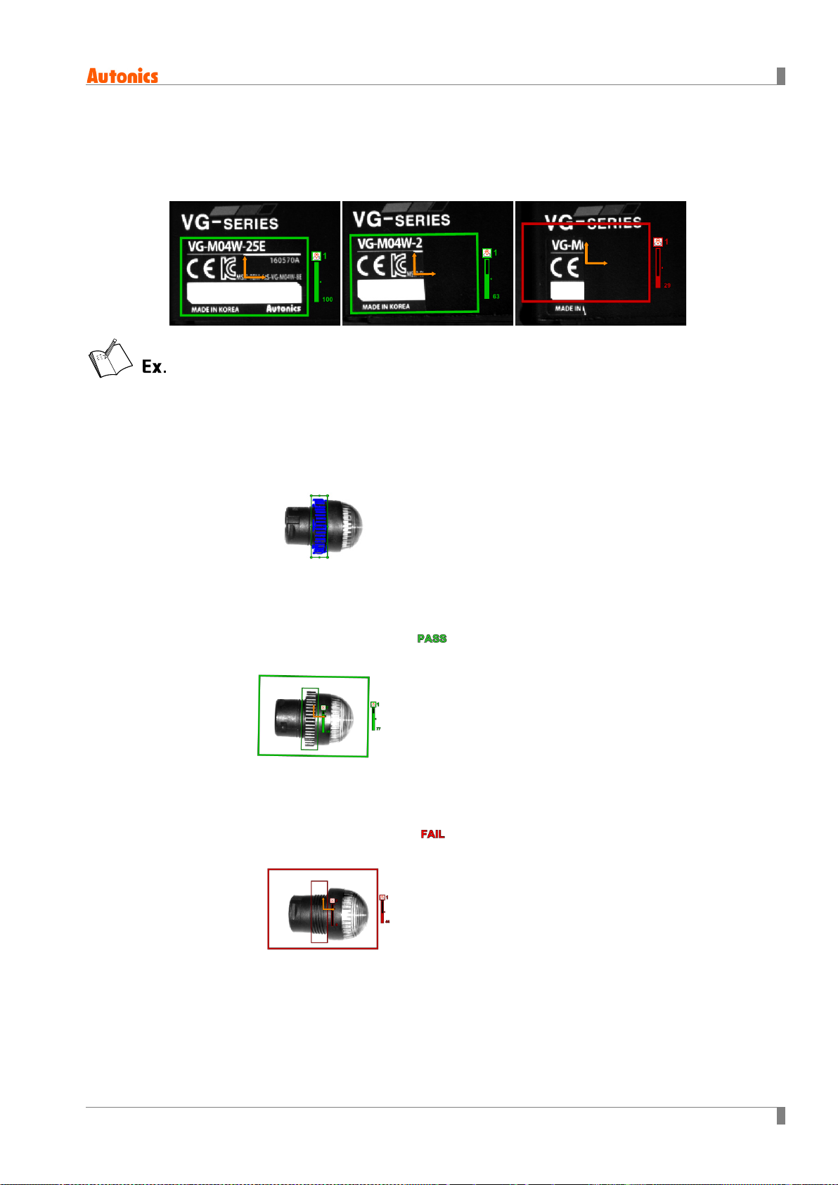
6 Vision Sensor Program [Vision Master]
※Threshold is the boundary value when a value is discontinuously changed.
※1. When set template of ROI is 50% similar with the input image in 50 similarity threshold, the
vision sensor regards them as the same target and outputs output signal.
Examples of pass/fail in the shape comparison inspection
Registering template of the inspection target (Similarity: 100% / Similarity threshold: 80%)
Passed shape comparison inspection (alignment applied)
Failed shape comparison inspection
© Copyright Reserved Autonics Co., Ltd. 97
Page 98
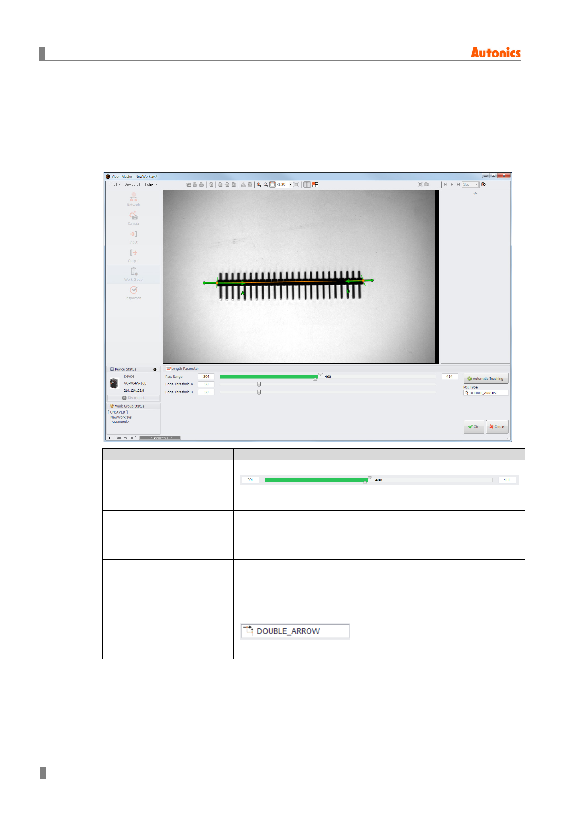
6 Vision Sensor Program [Vision Master]
No.
Item
Description
6.7.7 Length
You can use the length function to inspect the length between two edges. The length unit is pixel.
Base points of measuring length are two edges on each of two arrows. Length sets the pass
range based on the length between two registered edges. The measured length of the inspection
target within the pass range is regarded as Pass, while the measured length of the inspection
target out of the pass range is regarded as Fail.
It sets the pass/fail range of length.
1 Pass range
2 Edge threshold A/B
3 Automatic teaching
4 ROI type
5 OK/Cancel It registers work to work group or cancel to register.
Lower limit Measured ROI Upper limit
for pass length value for pass
It sets threshold to detect edge.
Only edges with high contrast can be detected in high edge
threshold, while edges with low contrast also can be detected in low
edge threshold.
Even if user set the pass range, it teaches pass range based on the
pixel of ROI.
It sets type of ROI to inspect.
In the ROI area, the program scans the edge in the arrow direction
and firstly detected edge becomes standard for inspection.
(two arrows)
※Threshold is the boundary value when a value is discontinuously changed.
98 © Copyright Reserved Autonics Co., Ltd.
Page 99
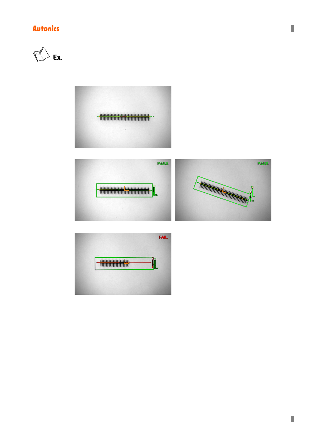
6 Vision Sensor Program [Vision Master]
Examples of pass/fail in the length inspection
Registering template of the inspection target (Length: 386 / pass range: 376 to 396)
Passed length inspection (alignment applied)
Failed length inspection
© Copyright Reserved Autonics Co., Ltd. 99
Page 100
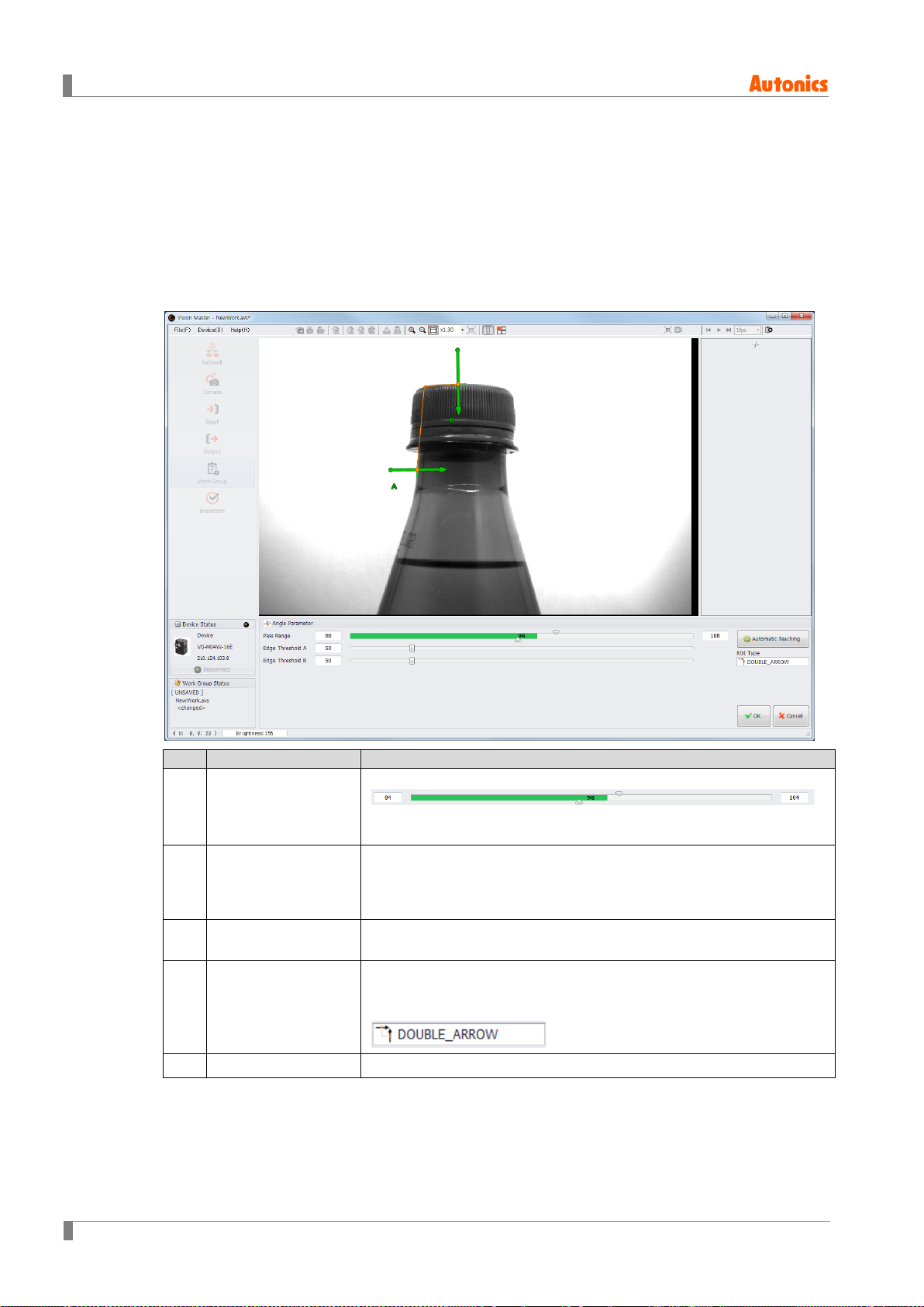
6 Vision Sensor Program [Vision Master]
No.
Item
Description
6.7.8 Angle
You can use the angle function to inspect the angle between two edges. The unit of angle is º
(degree).
Angle measures angle of crossing point which is between two edges of registered arrows.
It sets the pass range based on the angle between two registered edges. The measured angle of
the inspection target within the pass range is regarded as Pass, while the measured angle of the
inspection target out of the pass range is regarded as Fail.
It sets the pass/fail range of angle.
1 Pass range
2 Edge threshold A/B
3 Automatic teaching
4 ROI type
5 OK/Cancel It registers work to work group or cancel to register.
Lower limit Measured ROI Upper limit
for pass angle value for pass
It sets threshold to detect edge.
Only edges with high contrast can be detected in high edge threshold,
while edges with low contrast also can be detected in low edge
threshold.
Even if user set the pass range, it teaches pass range based on the
pixel of ROI.
It sets type of ROI to inspect.
In the ROI area, the program scans the edge in the arrow direction
and firstly detected edge becomes standard for inspection.
(two arrows)
※Threshold is the boundary value when a value is discontinuously changed.
100 © Copyright Reserved Autonics Co., Ltd.
 Loading...