

Page 1
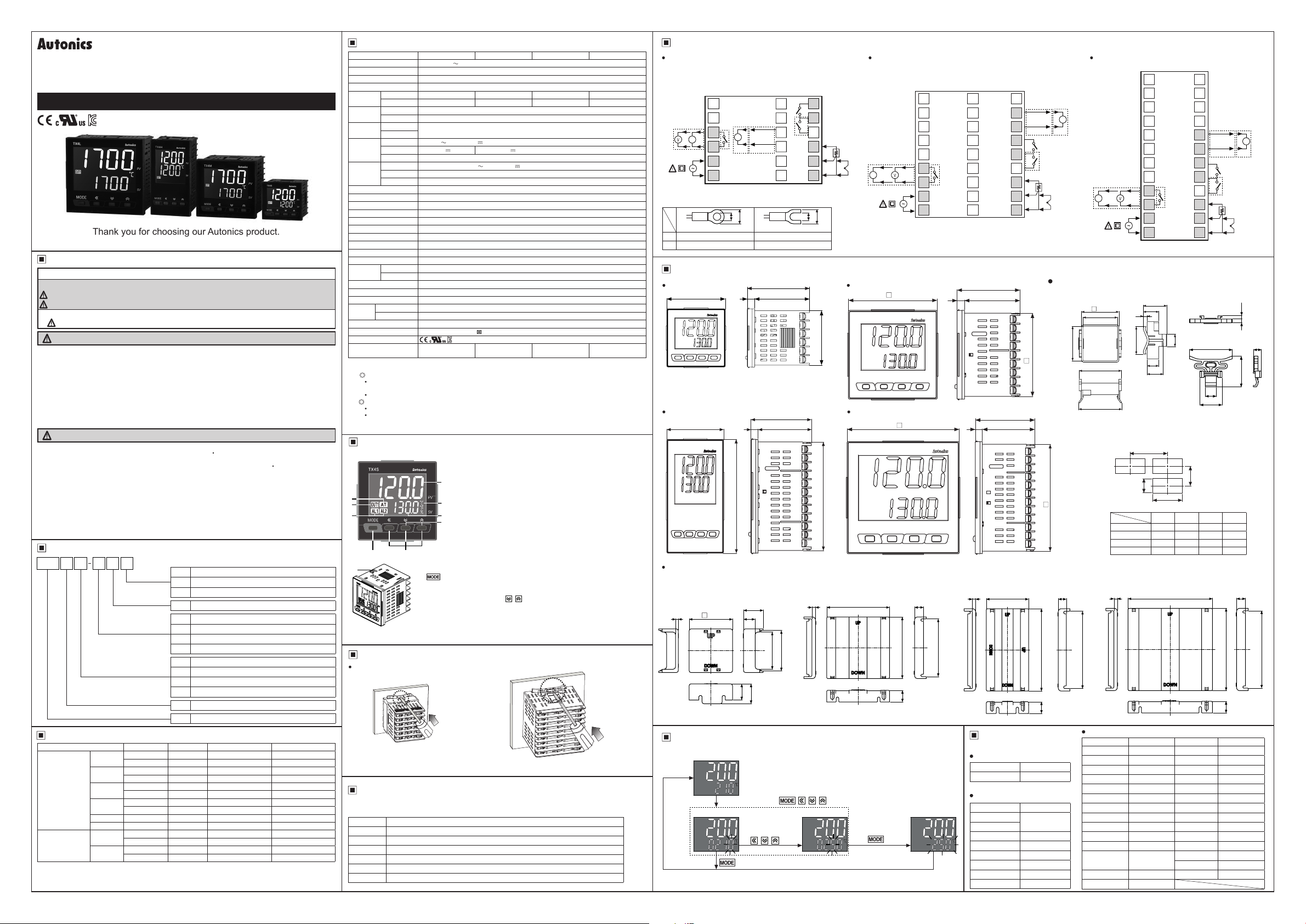
DRW170805AE
LCD Display PID Temperature Controller
TX SERIES
I N S T R U C T I O N M A N U A L
Please read the following safety considerations before use.
Safety Considerations
Please observe all safety considerations for safe and proper product operation to avoid hazards.
※
Safety considerations are categorized as follows.
※
Warning
Caution
※
The symbols used on the product and instruction manual represent the following
symbol represents caution due to special circumstances in which hazards may occur.
Warning
1. Fail-safe device must be installed when using the unit with machinery that may cause serious injury
or substantial economic loss. (e.g. nuclear power control, medical equipment, ships, vehicles,
railways, aircraft, combustion apparatus, safety equipment, crime/disaster prevention devices, etc.)
Failure to follow this instruction may result in re, personal injury, or economic loss.
2. Install on a device panel to use.
Failure to follow this instruction may result in electric shock.
3. Do not connect, repair, or inspect the unit while connected to a power source.
Failure to follow this instruction may result in electric shock or re.
4. Check 'Connections' before wiring.
Failure to follow this instruction may result in re.
5. Do not disassemble or modify the unit.
Failure to follow this instruction may result in electric shock or re.
Caution
1. When connecting the power input and relay output, use AWG 20 (0.50mm2) cable or over and tighten
the terminal screw with a tightening torque of 0.74 to 0.90N m.
When connecting the sensor input and communication cable without dedicated cable, use AWG 28 to
16 cable and tighten the terminal screw with a tightening torque of 0.74 to 0.90N m.
Failure to follow this instruction may result in re or malfunction due to contact failure.
2. Use the unit within the rated specications.
Failure to follow this instruction may result in re or product damage.
3. Use dry cloth to clean the unit, and do not use water or organic solvent.
Failure to follow this instruction may result in electric shock or re.
4. Do not use the unit in the place where ammable/explosive/corrosive gas, humidity, direct sunlight,
radiant heat, vibration, impact, or salinity may be present.
Failure to follow this instruction may result in re or explosion.
5. Keep metal chip, dust, and wire residue from owing into the unit.
Failure to follow this instruction may result in re or product damage.
Ordering Information
TX 4 S 1 4 R
Item
Input Type and Range
Input type Decimal point Display Input range(℃) Input range(℉)
Thermocouple
RTD
The above specications are subject to change and some models may be discontinued without notice.
※
Be sure to follow cautions written in the instruction manual and the technical descriptions (catalog,
※
homepage).
Thank you for choosing our Autonics product.
Failure to follow these instructions may result in serious injury or death.
Failure to follow these instructions may result in personal injury or product damage.
R
Relay output
S
SSR drive output
C
Selectable current output or SSR drive output
4
100-240VAC 50/60Hz
1
Alarm output 1
2
Alarm output 1+Alarm output 2
A
Alarm output 1+Alarm output 2+Trans. output
B
Alarm output 1+Alarm output 2+RS485 com. output
S
DIN W48×H48mm
M
DIN W72×H72mm
H
DIN W48×H96mm
L
DIN W96×H96mm
4
9999(4-digit)
TX
LCD display PID temperature controller
KCaH
KCaL
JIcH
JIcL
LIcH
LIcL
TCcH
TCcL
RPR
SPR
DPtH
DPtL
CUsH
CUsL
-50 to 1200 -58 to 2192
-50.0 to 999.9 -58.0 to 999.9
-30 to 800 -22 to 1472
-30.0 to 800.0 -22.0 to 999.9
-40 to 800 -40 to 1472
-40.0 to 800.0 -40.0 to 999.9
-50 to 400 -58 to 752
-50.0 to 400.0 -58.0 to 752.0
0 to 1700 32 to 3092
0 to 1700 32 to 3092
-100 to 400 -148 to 752
-100.0 to 400.0 -148.0 to 752.0
-50 to 200 -58 to 392
-50.0 to 200.0 -58.0 to 392.0
Digit
Option output
Size
K (CA)
J (IC)
L (IC)
T (CC)
R (PR) 1
S (PR) 1
DPt 100Ω
Cu50Ω
Control output
Power supply
1
0.1
1
0.1
1
0.1
1
0.1
1
0.1
1
0.1
Specications
Series
Power supply 100-240VAC 50/60Hz
Allowable voltage range 90 to 110% of rated voltage
Power consumption Max. 8VA
Display method 11-segments (PV: white, SV: green), other display (yellow) with LCD method
PV(W×H) 7.2×14mm 10.7×17.3mm 7.2×15.8mm 16×26.8mm
Character
size
SV(W×H) 3.9×7.6mm 6.8×11mm 6.2×13.7mm 10.7×17.8mm
RTD DPt100Ω, Cu50Ω (permissible line resistance max. 5Ω)
Input type
TC K (CA), J (IC), L (IC), T (CC), R (PR), S(PR)
RTD
Display
2
※
accuracy
TC
Relay 250VAC 3A, 30VDC 3A, 1a
Control
SSR
output
Current DC4-20mA or DC0-20mA (load resistance max. 500Ω)
Alarm output AL1, AL2: 250VAC 3A , 30VDC 3A 1a
Option
Trans. output DC4-20mA (load resistance max. 500Ω, output accuracy: ±0.3%F.S.)
output
Com. output RS485 communication output (Modbus RTU method)
Control method ON/OFF control, P, PI, PD, PID control
Hysteresis 1 to 100℃/℉ (0.1 to 50.0℃/℉) variable
Proportional band(P) 0.1 to 999.9℃/
Integral time(I) 0 to 9999 sec
Derivative time(D) 0 to 9999 sec
Control period(T) 0.5 to 120.0 sec
Manual reset 0.0 to 100.0%
Sampling period 50ms
Dielectric strength 3,000VAC 50/60Hz for 1 min (between primary circuit and secondary circuit)
Vibration 0.75mm amplitude at frequency 5 to 55Hz (for 1 min) in each X, Y, Z direction for 2 hours
Mechanical OUT, AL1/2: min 5,000,000 operations
Relay
life cycle
Electrical OUT, AL1/2: min 200,000 (250VAC 3A resistance load)
Insulation resistance Min. 100MΩ (at 500VDC megger)
Noise resistance Square shaped noise by noise simulator (pulse width 1㎲) ±2kV R-phase, S-phase
Memory retention Approx. 10 years (non-volatile semiconductor memory type)
Ambient temp. -10 to 50℃, storage: -20 to 60
Environment
Ambient humi. 35 to 85%RH, storage: 35 to 85%RH
Protection structure IP50 (front panel, IEC standards)
Insulation type
Approval
3
※
Weight
1: When using the unit at low temperature (below 0
※
Control output operates normally.
2: At room temperature(23℃±5℃)
※
TC R(PR), S(PR) , below 200℃: (PV ±0.5% or ±3℃, select the higher one) ±1-digit
TC L(IC), RTD Cu50Ω: (PV ±0.5% or ±2℃, select the higher one) ±1-digit
Out of room temperature range
TC R(PR), S(PR): (PV ±1.0% or ±5℃, select the higher one) ±1-digit
TC L(IC), RTD Cu50Ω: (PV ±0.5% or ±3℃, select the higher one) ±1-digit
3: The weight includes packaging. The weight in parenthesis is for unit only.
※
Environment resistance is rated at no freezing or condensation.
※
TX4S TX4M TX4H TX4L
※
●At room temperature: (23℃±5℃): (PV ±0.3% or ±1℃, select the higher one) ±1-digit
Out of room temperature: (PV ±0.5% or ±2℃, select the higher one) ±1-digit
●
Max. 12VDC ±2V 20mA
Double insulation (mark: , dielectric strength between primary circuit and secondary circuit: 3kV)
Approx. 146.1g
(approx. 86.7g)
, over 200℃: (PV ±0.5% or ±2℃, select the higher one) ±1-digit
℉
Max. 13VDC ±3V 20mA
℃
Approx. 233g
(approx. 143g)
℃), display cycle is slow.
Approx. 214g
(approx. 133g)
Approx. 290g
(approx. 206g)
1
Unit Description
1. Measured value (PV) component:
RUN mode: Displays current measured value (PV).
SETTING mode: Displays parameters.
2. Temperature unit(℃/℉) indicator:
1
Displays the set temperature unit as temperature unit [
parameter 2 group.
4
5
6
87
10
7. key:
8. Setting value adjutment key:
9. Digital input key:
10. PC loader port:
3. Setting value (SV) display component:
2
RUN mode: Displays setting value(SV).
SETTING mode: Displays setting value of parameter.
3
4. Auto-tuning indicator:
9
Flashes during auto-tuning every 1 sec.
5. Control output (OUT1) indicator:
Turns ON when MV is over 3.0% at cycle/phase control of SSR drive
※
output method.
6. Alarm output (AL1, AL2) indicator:
Turns ON when the corresponding alarm output turns ON.
Enters parameter group, returns to RUN mode, moves parameters,
and saves the setting value.
functions which is set at digital input key[
clear alarm output, auto-tuning).
DAQMaster installed in PC. Use this for connection EXT-US (converter cable,
sold separately) + SCM-US (USB/Serial converter, sold separately).
Press the + keys for 3 sec to execute the digital input key
It is for serial communication to set parameter and monitoring by
Enters SV setting mode and move digits.
Turns ON while control output is ON.
]of parameter 2 group (RUN/STOP,
DI-K
UNIT
] of
Installation
TX4S (48×48mm) series
(-) driver
※
Insert the unit into a panel, fasten the bracket by pushing with tools with a (-) driver.
Comprehensive Device Management Program[DAQMaster]
DAQMaster is a comprehensive device management software for setting parameters and monitoring
processes. DAQMaster can be downloaded from our web site at www.autonics.com.
Item Minimum specications
System IBM PC compatible computer with Pentium Ⅲ or above
Operations Windows 98/NT/XP/Vista/7/8/10
Memory 256MB+
Hard disk 1GB+ of available hard disk space
VGA Resolution: 1024×768 or higher
Others RS232C serial port (9-pin), USB port
●Other series
(-) driver
Shaded terminals is standard model.
RS485(A+)
RS485(B-)
13
14
15
16
17
18
51
※
<Forked>
AL1 OUT:
7
250VAC 3A 1a
RESISTIVE LOAD
8
AL2 OUT:
250VAC 3A 1a
RESISTIVE LOAD
9
A
10
B
11
B'
12
SENSOR
b
a
TX4M Series TX4H, L Series
OUT
Current
OUT
DC4-20mA
SSR
Load
13VDC±3V
500ΩMax.
+
mA
-
SOURCE
100-240VAC
50/60Hz 8VA
20mA Max.
+
-
+
-
TCRTD
TX4M
72
Connections
TX4S Series
OUT
SSR
12VDC±2V 20mA Max.
Current
DC0/4-20mA
Load 500ΩMax.
Relay
250VAC 3A 1a
30VDC 3A 1a
RESISTIVE LOAD
-
SOURCE
100-240VAC
50/60Hz 8VA
※
Use terminals of size specied below.
a Min. 3.0mm Min. 3.0mm
b Max.5.8mm Max.5.8mm
Dimensions
TX4S
1
2
+-+
mA
4
5
6
<Round>
mA
-
Communication
Output
Transfer Output
DC4-20mA
a
b
+
3
□48 6 45
44.8
TX4H
48 456
51
96
TX4L
96
91.5
Terminal cover (sold separately)
RMA-COVER(72×72mm)
RSA-COVER(48×48mm)
ᆞ
3 48.4
22
13
18
22
ᆞ
4
45
41
70
10
68.5
13
SV Setting
To change set temperature from 210℃ to 250
※
RUN mode
①
Press any key among
SV setting mode
②
Change SV
by , ,
Check SV
④
If there is no key input for 3 sec while setting SV, the new setting is applied and the unit will return to
※
RUN mode.
key
,
℃
, ,
once.
③
1 1019
2 1120
3 1221
OUT
4 1322
Relay
250VAC 3A 1a
30VDC 3A 1a
5 1423
RESISTIVE LOAD
6 1524
7 1625
8 1726
9 1827
64
Completes SV
setting
Communication
Output
Transfer Output
DC4-20mA
51
6
45
51
45
6
RHA-COVER(48×96mm)
ᆞ
3.8 47.2
Factory Default
SV setting
Parameter Factory default
-
Parameter 1 group
Parameter Factory default
AL1
AL2
AT OFF
REST 5)0
HYS 2
1250
P 1)0
I 240
D 49
RS485(A+)
RS485(B-)
AL1 OUT:
250VAC 3A 1a
RESISTIVE LOAD
AL2 OUT:
250VAC 3A 1a
RESISTIVE LOAD
A
B
B'
TCRTD
SENSOR
67.5
91.5
13
0
+
-
Bracket
91.5
1 13
2 14
+
mA
-
3 15
4 16
5 17
6 18
TX4S Series
ᆞ
44.9
OUT
Current
DC4-20mA
Load
500ΩMax.
+
mA
-
SOURCE
100-240VAC
50/60Hz 8VA
48.6
45
55
56
OUT
SSR
13VDC±3V
20mA Max.
+
-
OUT
7
Relay
250VAC 3A 1a
30VDC 3A 1a
8
RESISTIVE LOAD
9 21
10
11
12 24
30.5
20
5
36
16
15
21
19
20
22
23
TX4M/H/L Series
ᆞ
●Panel cut-out
A
D
Size
Model
TX4S Min. 65 Min. 65 45
TX4M Min. 90 Min. 90 68
TX4H Min. 115 Min. 65 45
TX4L Min. 115 Min. 115 92
RLA-COVER(96×96mm)
ᆞ
9
3.8
A B C D
B
C
94
86
Parameter 2 group
Parameter Factory default Parameter Factory default
IN-T KCaH AHYS 1
UNIT ?C LBaT 0
IN-B 0 LBaB 2
MAvF )1 FS-L -50
L-SV -50 FS-H 1200
H-SV 1200 ADRS 1
O-FT HEAT BPS 96
C-MD PID PRTY NONE
OUT CURR STP 2
SSrM STND RSwT 20
oMA 4-20 COMW EnA
(Relay)
2)0 DI-K STOP
T
@0 ErMV )0
(SSR drive)
AL-1 AM!A LOC OFF
AL-2 AM@A
Communication
Output
Transfer Output
DC4-20mA
RS485(A+)
RS485(B-)
A
B
B'
SENSOR
46
11.9
23.9
(unit: mm)
+ 0.6
45
0
+ 0.7
68
0
+ 0.6
92
0
+ 0.8
92
0
91.5
13
+
mA
-
AL1 OUT:
250VAC 3A 1a
RESISTIVE LOAD
AL2 OUT:
250VAC 3A 1a
RESISTIVE LOAD
+
-
TCRTD
(unit: mm)
4 3.5
8.5
33
+ 0.6
0
+ 0.7
0
+ 0.8
0
+ 0.8
0
10
86
Page 2

me
Parameter Groups
RUN mode
Press any key among
, , , once.
SV setting Parameter 1 group[
2 sec
PAR1
] Parameter 2 group[
3 sec
Order of parameter setup
※
All parameters are related one another. Set the parameters as above order.
●
If there is no key input for 30 sec while setting parameters, the new settings are ignored, and the unit will
※
return to RUN mode with previous settings.
When returning to RUN mode by holdin g the
※
re-enter the first parameter of previous parameter group.
Hold the + + keys for 5 sec in RUN mode, to enter re-set parameter menu. Select '
※
parameters are reset as factory default.
● Parameter 2 group
RUN mode
3 sec
Input sensor
Input digital
SV low-limit
SV high-limit
output mode
output low-
Trans. output
waiting time
PAR2
IN-T KCaH
Temp. unit
UNIT ?F?C
Input
IN-B 0
correction
MAvF )1
lter
L-SV -50
value
H-SV 1200
value
Control
O-FT HEAT COOL
Control
C-MD PID ONOF
method
Control
output
selection
SSR drive
method
Current
Control
operation
operation
hysteresis
monitoring
detection
limit value
high-limit
Comm.
address
Comm.
Comm.
parity-bit
Comm.
stop-bit
Comm.
response
Comm.
input key
output MV
for input
OUT CURR SSR
output
SSrM STND CYCL PHAS
output
oMA 4-20 0-20
range
cycle
AL1
AL2
Alarm
output
LBA
time
LBA
band
Trans.
value
T 2)0
AL-1 LBaAAM!A
AL-2 AM@A
AHYS 1
LBaT 0
LBaB 2
FS-L -50
FS-H 1200
ADRS 1
BPS 96
speed
STP 2 1
RSwT 20
COMW EnA DIsA
write
Digital
DI-K
Control
ErMV )0
break
Lock
LOC LOC1 LOC2 LOC3OFF
Parameter 2 group Parameter 1 group SV setting
key for over
1: : Press any key among , , .
※
2: Press the key once after changing the setting value, to save the setting
※
※1
value and move to the next parameter
Hold the key for 3 sec to save the setting value and return to RUN mode
4 sec
※
after changing the setting value.
Dotted parameters may not appear by model type or other parameter
※
settings.
Setting range: Refer to '▣ Input Type And Range'.
When changing the setting value, SV, [
※
2
※
AL1, AL2, LBaB, AHYS
reset.
※
Setting range: -999 to 999℃/℉(-199.9 to 999.9℃/℉)
Setting range: 0.1 to 120.0 sec
Setting range: Within temperature range of each sensor [
When changing the setting value, and SV
※
When changing the setting value, [
※
[
Appears only in selectable current output or SSR drive
※
output model(TX4 - 4C).
※
Setting range: 0.5 to 120.0 sec
Appears only when control method[
※
Does not appear when SSR drive output is set as
※
3 sec, press the
] parameters of parameter 2 group are
When changing the setting value, SV, [
L-SV, AL1, AL2, LBaB, AHYS
parameter 2 group are reset.
] is reset as
DI-K
Appears only when control output[
.
OFF
Appears only in SSR drive output model
※
(TX4 - 4S).
C-MD
AM!A AM!B
Alarm operation
※
Press the key to switch 'Alarm operation'
※
'Alarm option' setting.
Set method is same as AL1 alarm
※
operation[
AL-1
Appears only in alarm output 2 models.
※
Setting range: 1 to 100℃/℉(0.1 to 50.0℃/℉)
Does not appear when AL1/AL2 alarm operation[
※
as
AM)_/SBa/LBa
Setting range: 0 to 9999 sec (automatically set during auto-tuning)
Appears only when alarm operation[
※
Setting range: 0 to 999℃/℉ (0.0 to 999.9℃/℉)
※
Setting range: Refer to '▣ Input Type and Range'.
※
Setting range: 1 to 127
Setting range: 24, 48, 96, 192, 384 bps
Multiply 100 to read the setting value.
(automatically set during auto-tuning)
Appears only when alarm operation [
and [
] is not set as 0.
LBaT
Appears only in transmission output model(TX4 -A4 ).
].
Alarm option
※
.
AL-1, AL-2
NONE EVEN ODDPRTY
Setting range: 5 to 99ms
AlRE OFFATSTOP
Setting range: 0.0 to 100.0%
Only )0(OFF)/
※
[
] is set as
C-MD
When control method [
※
value is below
Setting range:
(ON) appear when control method
10)0
.
ONOF
] is changing
C-MD
, it is reset as )0.
10)0
Unlock
OFF
Parameter 2 group lock
LOC1
Parameter 1,2 group lock
LOC2
Parameter 1,2 group, SV setting lock
LOC3
4 sec
3 sec
key within
YES
IN-B, H-SV/L-SV
IN-B, H-SV
] parameters of
H-SV≥(L-SV
, SV is reset as
>
H-SV
] is reset as )0,
ErMV
] is set as
OUT
] is
.
PID
, or
CYCL
When changing the
※
setting value,
[
AL1, AL2
parameter of
parameter 1 group
is reset.
AL-1, AL-2
] is set as
AL-1, AL-2
] is set as
Appears in RS485
※
communication output
model(TX4 -B4 ).
AT does not appear when
※
control method [
as
ONOF
PID↔ONOF
C-MD
.
and the setting
PAR2
1 sec to
' and all
H-SV.
CURR
PHAS
]
] is set
LBa
LBa
] is set
● Parameter 1 group
]
,
+1digit)]
3 sec
/
Alarm[
Alarm operation
RUN mode
PAR1
AL1 temperature
AL1
AL2 temperature
AL2
Auto-tuning
Proportional band
Integral time
Derivative time
Manual reset
REST
Hysteresis
Alarm
operation
AT
P
I
D
AL-1/ AL-2
AM!A
1: : Press any key among , , .
※
2: Press the key once after changing the setting value, to save the setting
※
value and move to the next parameter
Hold the key for 3 sec to save the setting value and return to RUN mode
※
2 sec
after changing the setting value.
Dotted parameters may not appear by model type or other parameter
※
settings.
1
※
Alarm
option
Setting range: Deviation alarm(-[F.S] to [F.S]),
1250
2
※
※
※
1250
Setting range: 0.1 to 999.9℃/
1)0
Setting range: 0 to 9999 sec
Integral operation will be OFF
※
240
when the setting value is '0'
Setting range: 0 to 9999 sec
Derivative operation will be OFF
※
49
when the setting value is '0'
Setting range: 0.0 to 100.0%
Only appears in P, PD control.
※
5)0
Setting range: 1 to 100℃/℉ (0.1 to 50.0℃/℉)
Only appears when control method [
※
2HYS
set as
Set both alarm operation and alarm option by combining.
]
Each alarm operates individually in two alarm output models.
When the current temperature is out of alarm range, alarm
clears automatically. If alarm option is alarm latch or alarm latch
and standby sequence 1/2, press digital input key( + 3 sec,
digital input key[
turn OFF the power and turn ON to clear alarm.
Absolute value alarm(temperature range)
Does not appear when AL1/AL2 alarm operation[
of parameter 2 group is set as
Only alarm output 2 models have [
When setting as ON, the unit starts auto-tuning. After
※
completing,
ONOFF
During auto-tuning, the auto-tuning in dicator
※
ashes (every 1 sec).
.
ONOF
DI-K
AM)_/SBa/LBa
AL2
is automatically set.
OFF
℉
※
C-MD
] of parameter 2 group set as
].
Only appears when control
method [
2 group is set as
] of parameter 2 group is
Mode Name Alarm operation Description
- -
AM)_
H
.
.
.
Deviation
high-limit
AM!
alarm
Deviation
low-limit
AM@
alarm
Deviation
high/low-
AM#
limit
alarm
Deviation
high/lowlimit
AM$
reserve
alarm
Absolute
value high
AM%
limit alarm
Absolute
value low
AM^
limit alarm
Sensor
SBa
break alarm
Loop break
LBa
alarm
H: Alarm output hysteresis [
※
Alarm option
Option Name Description
Standard
AM .A
alarm
Alarm latch
AM .B
Standby
AM .C
sequence 1
Alarm latch
and standby
AM .D
sequence 1
Standby
AM .E
sequence 2
Alarm latch
and standby
AM .F
sequence 2
Condition of re-applied standby sequence for standby sequence 1, alarm latch and standby sequence 1: Power ON
※
Condition of re-applied standby sequence for standby sequence 2, alarm latch and standby sequence 2: Power ON,
changing set temperature, alarm temperature [
to RUN mode.
Sensor break alarm
The function that alarm output will be ON when sensor is not connected or when sensor's disconnection is
detected during temperature controlling. You can check whether the sensor is connected with buzzer or other
units using alarm output contact. It is selectable between standard alarm [
OFF ON
SV
100℃PV110℃
High-limit deviation: Set as 10℃ High-limit deviation: Set as -10℃
H
OFFON
PV
90℃SV100℃
Low-limit deviation: Set as 10℃ Low-limit deviation: Set as -10℃
OFF ON
Alarm absolute-value: Set as 90℃ Alarm absolute-value: Set as 110℃
Alarm absolute-value: Set as 90℃ Alarm absolute-value: Set as 110℃
H H
PV
90℃
High, Low-limit deviation: Set as 10℃
H H
OFF OFFON
PV
90℃
High, Low-limit deviation: Set as 10℃
H
PV
90℃SV100℃
H
OFFON
PV
SV
90℃
100℃
-
-
]
AHYS
If it is an alarm condition, alarm output is ON. If it is a clear alarm condition, alarm output
is OFF.
If it is an alarm condition, alarm output is ON and maintains ON status.
(Alarm output HOLD)
First alarm condition is ignored and from second alarm condition, standard alarm
operates. When power is supplied and it is an alarm condition, this rst alarm condition is
ignored and from the second alarm condition, standard alarm operates.
If it is an alarm condition, it operates both alarm latch and standby sequence. When
power is supplied and it is an alarm condition, this rst alarm condition is ignored and
from the second alarm condition, alarm latch operates.
First alarm condition is ignored and from second alarm condition, standard alarm
operates. When re-applied standby sequence and if it is alarm condition, alarm output
does not turn ON. After clearing alarm condition, standard alarm operates.
Basic operation is same as alarm latch and standby sequence 1. It operates not only by
power ON/OFF, but also alarm setting value, or alarm option changing. When re-applied
standby sequence and if it is alarm condition, alarm output does not turn ON. After
clearing alarm condition, alarm latch operates.
H
OFF ON
PV
90℃SV100℃
SV
100℃PV110℃
OFFON ON
OFF ON
AL1, AL2
PV
110℃
PV
110℃
SV
100℃PV110℃
SV
100℃PV110℃
] or alarm operation [
SV
100℃
SV
100℃
H
No alarm output
If deviation between PV and SV as
high-limit is higher than set value
of deviation temperature, the alarm
output will be ON.
H
OFFON
If deviation between PV and SV as
low-limit is higher than set value of
deviation temperature, the alarm
output will be ON.
If deviation between PV and SV
as high/low-limit is higher than set
value of deviation temperature, the
alarm output will be ON.
If deviation between PV and SV
as high/low-limit is higher than set
value of deviation temperature, the
alarm output will be OFF.
If PV is higher than the absolute
value, the output will be ON.
H
OFFON
If PV is lower than the absolute
value, the output will be ON.
It will be ON when it detects sensor
disconnection.
It will be ON when it detects loop
break.
], switching STOP mode
AL-1, AL-2
] or alarm latch [
SBaA
C-MD
SBaB
AL-1, AL-2
.
] of parameter
.
PID
), or
AlRE
].
Functions
Input correction[
Controller itself does not have errors but there may be error by external input temperature sensor. This function
is for correcting this error.
Ex) If actual temperature is 80℃ but controller displays 78℃, set input correction value [
controller displays 80
As the result of input correction, if current temperature value (PV) is over each temperature range of input
※
sensor, it displays
Input digital lter[
If current temperature (PV) is uctuating repeatedly by rapid change of input signal, it reects to MV and
stable control is impossible. Therefore, digital lter function stabilizes current temperature value.
For example, set input digital lter value as 0.4 sec, and it applies digital lter to input values during 0.4 sec
and displays these values. Current temperature may be dierent by actual input value.
]
SSR drive output method (SSRP function)[
ㆍ
SSRP function is selectable one of standard ON/OFF control, cycle control, phase control by
utilizing standard SSR drive output.
ㆍ
This function parameter appears only in SSR drive output model (TX4 - 4S).
ㆍ
Realizing high accuracy and cost effective temperature control with both current output (4-20mA)
and linear output(cycle control and phase control)
ㆍ
Select one of standard ON/OFF control [
parameter of parameter 2 group. For cycle control, connect a zero cross turn-on SSR or random
turn-on SSR. For phase control, connect random turn-on SSR.
Temperature controller
※
When selecting cycle or phase control mode,
controller must be the same.
Control cycle[T] is able to set only when control method[
※
drive output method [
In case of selectable current output or SSR drive output model(TX4 - 4C), this parameter does not appear.
※
Standard ON/OFF control by SSR is only available.
1) Standard ON/OFF control [
Controls ON (100% output)/OFF
(0% output) as same as standard
relay output.
2) Cycle control [
Controls the load by repeating
output ON / OFF according to the
rate of output within setting cycle
based on certain period (50-cycle).
Control accuracy is almost the
same with phase control’s.
This control has improved ON/
OFF noise than phase control’s
due to zero cross type which turns
ON/OFF at zero point of AC.
3) Phase control [
Controls the load by controlling
the phase within AC half cycle.
Serial control is available.
Must use random turn-on SSR for
this mode.
Current output range[
In case of selectable current output or SSR drive output model(TX4S- 4C), when control output [
parameter 2 group is set as [
current output.
Hysteresis[
Set interval between ON and OFF of control output for ON/OFF
control.
If hysteresis is too narrow, hunting(oscillation, chattering) could
●
occur due to external noise.
In case of ON / OFF control mode, even if PV reaches stable
●
status, there still occurs hunting. It could be due to hysteresis
[
HYS
location. In order to reduce hunting to a minimum, it is required
to take into following factors consideration when designing temp.
controlling; proper Hysteresis [
characteristics, sensor’s response and location.
Loop break alarm(LBA)
It checks control loop and outputs alarm by temperature change of the subject. For heating control(cooling
control), when control output MV is 100%(0% for cooling control) and PV is not increased over than LBA
detection band [
control) and PV is not decreased below than LBA detection band [
alarm output turns ON.
Start control
to
to The status of changing control output MV (LBA monitoring time is reset.)
to
to Control output MV is 0% and loop break alarm (LBA) turns and maintains ON.
to
to
to
to
When executing auto-tuning, LBA detection band[
※
on auto tuning value. When alarm operation mode [
detection band [
HYS
] setting value, load’s response characteristics or sensor’s
When control output MV is 100%, PV is increased over than LBA detection band [
LBA monitoring time [
When control output MV is 0% and PV is not decreased below than LBA detection band [
during LBA monitoring time [
The status of changing control output MV (LBA monitoring time is reset.)
When control output MV is 100% and PV is not increased over than LBA detection band [
during LBA monitoring time [
When control output MV is 100% and PV is increased over than LBA detection band [
during LBA monitoring time [
The status of changing control output MV (LBA monitoring time is reset.)
]
IN-B
℃.
or
HHHH
MAvF
(TX Series)
Power
100-240VAC
50/60Hz
]
CYCL
]
PHAS
.
LLLL
]
] is set as
SSrM
]
STND
]
oMA
], you can select high/low-limit range, 4-20mA [
CURR
]
], heater’s capacity, thermal
HYS
] during LBA monitoring time [
LBaB
LBaT
] and LBA monitoring time [
LBaB
]
SSrM
], cycle control [
STND
SSR voltage output
(TX4S: 12VDC
TX4M/H/L: 13VDC)
] , phase control [
CYCL
SSR module
the power supply for a load and a temperature
]of parameter group 2 is set as
C-MD
ON ONOFF OFF
50 Cycle 50 Cycle
50% 80%
10% 50%
] or 0-20mA [
4-20
Control
output
], or when control output MV is 0%(100% for cooling
LBaT
], loop break alarm (LBA) turns ON after LBA monitoring time.
], loop break alarm (LBA) turns ON after LBA monitoring time.
], loop break alarm (LBA) turns OFF after LBA monitoring time.
] and LBA monitoring time are automatically set based
LBaB
AL-1, AL-2
] parameter is displayed.
LBaT
] during LBA monitoring time [
LBaB
] is set as loop break alarm(LBA)[
Heating operation
ON OFF
Hysteresis
OUT
OUT
AC
AC
OUT
STND
AC
].
LBaT
LBaT
LBaT
.
IN-B
[
HYS
] as '2' and
] at
PHAS
SSrM
Load
and SSR
PID
]
OUT
] of
0-20
]
SV
LBaT
Ti
] during
LBaB
LBaB
LBaB
]
LBaB
LBa
Digital input key( + 3 sec)[
Parameter
OFF
RUN/STOP
Operation
It does not use digital input key function.
OFF
Pauses control output. Auxiliary output (except loop break alarm, sensor break alarm)
except Control output operates as setting. Hold the digital input keys for 3 sec to restart.
STOP
RUN RUN
Clears alarm output by force.
Clear alarm
Auto-tuning
Control output MV for input break[
When input sensor is break, set control output MV.
When control method[
or
(ON). When control method[
10)0
Communication Setting
It is for parameter setting and monitoring via external devices (PC, PLC, etc.).
Applicable for models with RS485 communication output through option output(TX4 -B4 ).
Please refer to ' Ordering Information'.
Interface
Comm. protocol
Connection type RS485
Application standard EIA RS485 Compliance with Start bit 1-bit (xed)
Max. connection
Synchronous method
Comm. method Two-wire half duplex Stop bit 1-bit, 2-bit (default)
Comm. eective range
● Application of system organization
Computer
※
It is recommended to use Autonics communication converter; SCM-WF48 (Wi-Fi to RS485·USB wireless
communication converter, sold separately), SCM-US48I (USB to RS485 converter, sold separately), SCM-38I
(RS232C to RS485 converter, sold separately), SCM-US (USB to Serial converter, sold separately).
Please use twisted pair wire, which is suitable for RS485 communication, for SCM-WF48, SCM-US48I and
SCM-38I.
Manual
For the detail information and instructions of communication setting and Modbus mapping table, please refer
to user manual for communication, and be sure to follow cautions written in the technical descriptions (catalog,
homepage).
Visit our homepage (www.autonics.com) to download manuals.
(only when alarm option is alarm latch, or alarm latch and standby sequence 1/2 .)
AlRE
This function is applied when present value is out of alarm operation range but alarm
output is ON. Alarm operates normally right after clearing alarm.
Starts/Stops auto-tuning. This function is same as auto-tuning[AT] of parameter 1
group. (You can start auto-tuning [AT] of parameter 1 group and stop it by digital input
key.)
AT
This parameter AT appears only when control method [
※
is set as
parameter is changed as
] of parameter 2 group is set as
C-MD
Modbus RTU
31 units (address: 01 to 127)
Asynchronous Parity bit None (default), Odd, Even
Max. 800m
RS232C/
USB/Wi-Fi
Comm.
converter
B (-)
ON OFF
A (+)
]
DI-K
t t tt
STOP STOP RUN
. When control method [
PID
]
ErMV
] is set as
C-MD
RS485
PID
A (+) B (-) A (+) B (-) A (+) B (-)
RS485
DEVICE
] parameter 2 group is set as
C-MD
.
OFF
, set control output MV as )0(OFF)
ONOF
, setting range for control output MV is )0 to
Comm. speed
Response waiting time
Data bit 8-bit (xed)
※
Only for RS485 communication output model.
Terminating resistance
(100 to 120Ω)
RS485
DEVICE
#1
#2
C-MD
4800, 9600 (default), 19200, 38400, 115200 bps
5 to 99ms (default: 20ms)
RS485
DEVICE
#30
Error
Display Description Troubleshooting
Flashes when input sensor is disconnected or sensor is not connected. Check input sensor status.
OPEN
Flashes when measured value is higher than input range.
HHHH
Flashes when measured value is lower than input range.
LLLL
Temp.
Cautions during Use
1. Follow instructions in 'Cautions during Use'. Otherwise, It may cause unexpected accidents.
2. Check the polarity of the terminals before wiring the temperature sensor.
For RTD temperature sensor, wire it as 3-wire type, using cables in same thickness and length.
For thermocouple (CT) temperature sensor, use the designated compensation wire for extending wire.
3. Keep away from high voltage lines or power lines to prevent inductive noise.
In case installing power line and input signal line closely, use line filter or varistor at power line and shielded
],
wire at input signal line.
Do not use near the equipment which generates strong magnetic force or high frequency noise.
4. Do not apply excessive power when connecting or disconnecting the connectors of the product.
5. Install a power switch or circuit breaker in the easily accessible place for supplying or disconnecting the
power.
6. Do not use the unit for other purpose (e.g. voltmeter, ammeter), but temperature controller.
7. When changing the input sensor, turn off the power first before changing.
After changing the input sensor, modify the value of the corresponding parameter.
8. Do not overlapping communication line and power line.
Use twisted pair wire for communication line and connect ferrite bead at each end of line to reduce the effect
of external noise.
9. Make a required space around the unit for radiation of heat.
For accurate temperature measurement, warm up the unit over 20 min after turning on the power.
10. Make sure that power supply voltage reaches to the rated voltage within 2 sec after supplying power.
11. Do not wire to terminals which are not used.
12. This unit may be used in the following environments.
Indoors (in the environment condition rated in 'Specifications') ②Altitude max. 2,000m
①
Pollution degree 2
③
Major Products
Photoelectric Sensors Temperature Controllers
Fiber Optic Sensors Temperature/Humidity Transducers
]
Door Sensors SSR/Power Controllers
Door Side Sensors Counters
Area Sensors Timers
Proximity Sensors Panel Meters
Pressure Sensors Tachometer/Pulse(Rate)Meters
Rotary Encoders Display Units
]
Connector/Sockets Sensor Controllers
Switching Mode Power Supplies
Control Switches/Lamps/Buzzers
I/O Terminal Blocks & Cables
Stepper Motors/Drivers/Motion Controllers
Graphic/Logic Panels
Field Network Devices
Laser Marking System(Fiber, Co₂, Nd:yag)
], LBA
Laser Welding/Cutting System
HEADQUARTERS:
18, Bansong-ro 513beon-gil, Haeundae-gu, Busan,
South Korea, 48002
TEL: 82-51-519-3232
E-mail:
When input is within the
rated input range, this display
disappears.
Installation category II
④
http://www.autonics.com
Digital input key
(t: over 3 sec)
] parameter 2 group
B (-)
A (+)
ONOF
10)0
RS485
DEVICE
#31
, this
DRW170805AE
.
 Loading...