

TPS30 Series
Non-indicating Pressure Transmitters
Features
• Robust build allows high or low pressure measurement in high
and low temperature environments.
: high pressure (0 to 60MPa), low pressure (0 to 2 MPa)
: temperature range (-40 to 125℃) (may vary by model)
• For diverse applications including packaging machines, heavy
machinery, factories, and shipbuilding.
• Pressure measurement of any gas, liquid, or oil.
• 316L stainless steel diaphragm for high corrosion resistance.
• Compact size allows easy installation in tight or limited spaces.
• 1ms high-speed response rate.
• Analog output: Voltage (1-5 VDC), Current (DC 4-20 mA)
• Built-in reverse polarity protection circuit.
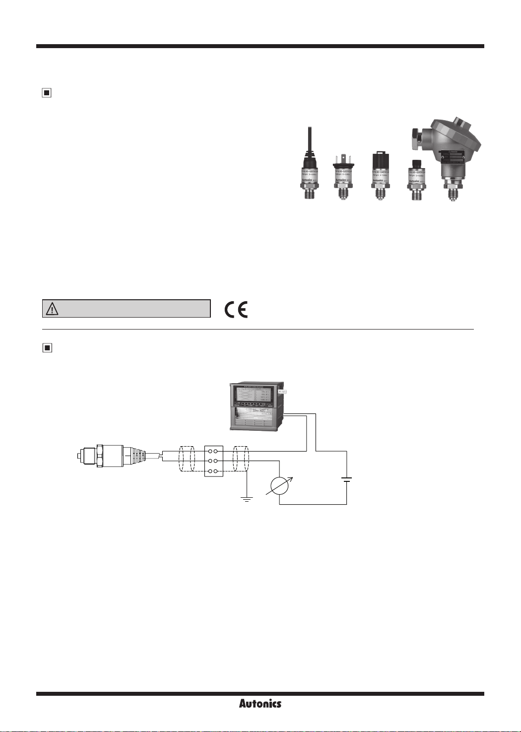
Various connector types
•
: cable type, DIN43650-A connector type,
DT04-3P connector type, M12 connector type, head type.
• Available thread sizes: G3/8, G1/4, R1/2
Protection structure: IP67 (IEC standard)
•
(except DIN43650-A connector type: IP65)
Please read “Safety Considerations”
in the instruction manual before using.
=I
&:,____
___
____.I
CE:
Cable type DIN43650-A
connector
type
connector
type
M12
connector
type
Head typeDT04-3P
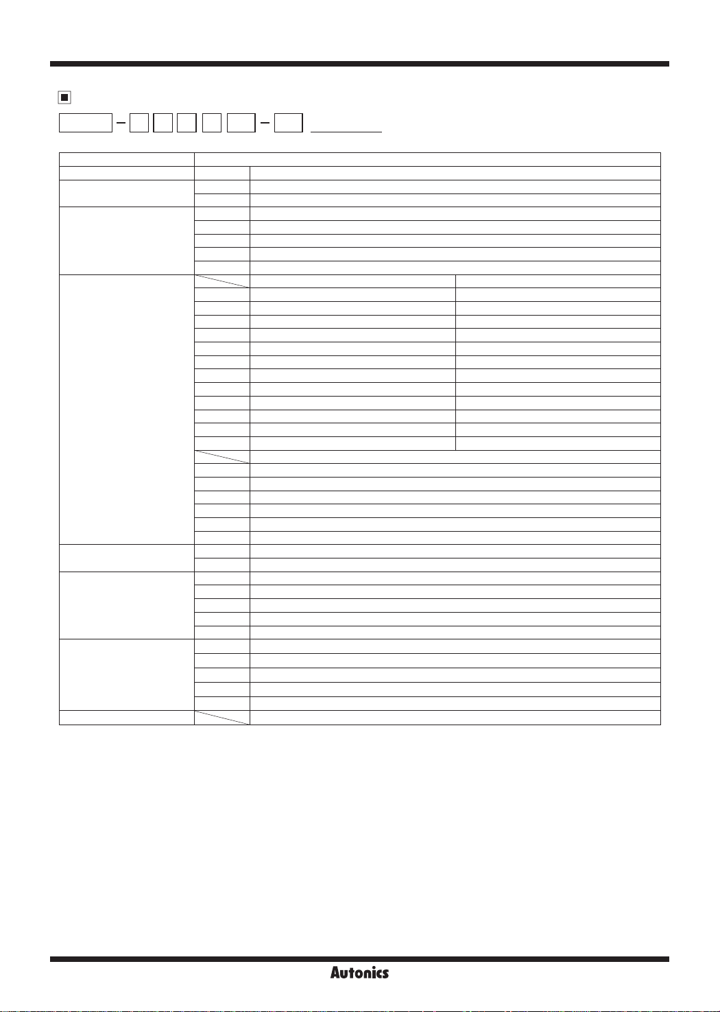
Example of External Connections
KRN100 (100mm hybrid recorder)
TPS30
+
-
Terminal
I'
I'
'I 'I
+
-
+ +
-
DC4-20mA
Power 24VDC load 600Ω
Output DC4-20mA 2 wire
24VDC
-
G-60
Autonics
Non-indicating Pressure Transmitters
Ordering Information
~I-
①
G 2 9 V G8 00TPS30
□□□□□-□--
② ③ ④ ⑤ ⑥ ⑦ ⑧
Description
①
Item
②
Measurement pressure
TPS30 Non-indicating Pressure Transmitters
G Gauge pressure, sealed gauge pressure
A Absolute pressure
1 Head type
2 DIN43650-A connector type
③
Cable
3 M12 connector type
4 DT04-3P connector type
5 Cable type
Gauge pressure Absolute pressure
3 0 to 0.1MPa 0 to 0.1MPa
---------
4 0 to 0.2MPa 0 to 0.2MPa
5 0 to 0.7MPa 0 to 0.7MPa
6 0 to 1MPa 0 to 1MPa
7 0 to 2MPa 0 to 2MPa
※
2
④
Pressure range
8
※
2
9
※
2
A
※
2
B
※
2
C
※
2
D
※
2
E
0 to 3.5MPa
0 to 5MPa
0 to 10MPa
0 to 20MPa
0 to 40MPa
0 to 50MPa
0 to 60MPa
Sealed gauge pressure
F -0.1 to 0MPa
---------
G - 0 .1 to 0 .1M Pa
H -0.1 to 0.7MPa
J -0.1 to 1MPa
K -0.1 to 2MPa
Z Others
⑤
Output type
V Voltage (1-5VDC) output
A Current (DC4-20mA) output
G8 G3/8 (PF)(EN387)
G4 G1/4 (PF)(EN387)
⑥
Pressure port
R2 R1/2 (PT)(DIN3852)
N4 NPT1/4 (DIN3852)
※
3
ZZ
Others (option)
00 Not used
⑦
Option
(connector cable)
※
2I "I" type 2m
2L "L" type 2m
4
5I "I" type 5m
5L "L" type 5m
⑧
User pressure range User pressure range
※
1: The pressure is sealed gauge pressure. The unit is sealed structure. It is based on atmospheric pressure 101.3kPa (1.013bar).
※
2: G1/4 is the standard pressure port. For the other pressure ranges, G3/8, R1/2 are standard pressure ports.
※
The option ports are sold separately. In case of large amount ordering, contact he Autonics for manufacturing the requested pressure port.
3:
※
4: Only for M12 connector type.
※
5: Write the desired pressure range and it is the default of user pressure range.
-----..........
(0 to 0.5MPa)
※
1
※
5
※
1
-
-
-
-
-
-
-
(select "Z" at ④Pressure range)
G-61
TPS30 Series
Specifications
Series TPS30
Pressure type
Rated pressure range (MPa)
Expanded analog output
range (MPa)
Max. pressure range (MPa) 0.6 0.6 3 3 3 0.6 0.6 3 3 3 10 20 50 80 120 120 120
Burst pressure (MPa) 0.6 0.6 3 3 3 0.6 0.6 3 3 3 15 30 75 120 160 160 160
Measured materials Liquid, gas, oil (inappropriate to corrosion environment for stainless steel 316L)
Power supply
Permissible voltage range 90 to 110% of rated voltage
Current
consumption
Response time Max. 1ms
Protection circuit Reverse polarity protection circuit
Output type Voltage output type: 1-5VDCᜡ Current output type: DC4-20mA
Compensation
temperature
Accuracy Max. ±0.5% F.S. (including linearity, hysteresis, reproducibility)
Linearity Max. ±0.2% F.S.
Hysteresis Max. ±0.2% F.S.
Temp. Zero Shift Max. ±0.1% F.S./10℃ (standard), max. ±0.25% F.S./10℃ (ma x .)
Temp. Span Shift Max. ±0.1% F.S./10℃ (standard), max. ±0.25% F.S./10℃ (ma x .)
Temperature
characteristics
Load resistance Current output type: max. 700Ω (supplying 24VDC)
Dielectric strength 500VAC 50/60Hz for 1 minute
Insulation
resistance
Ambient
temp.
Environment
Ambient humidity 35 to 85%RH
Fluid temp. -40 to 125
Vibration 10g, 20 to 2,000Hz 20g, 20 to 2,000Hz
Shock 100g/ 6ms 50 0g /1ms
Tightening torque Max. 10N.m
Protection
structure
Material
Connection Voltage output type: +, -, Vout Current output type: +, Approval
※
2
Weight
※
1: The sensor is sealed structure. It is based on atmospheric pressure 101.3kPa (1.013bar).
※
2: The weight includes packaging. The weight in parenthesis is for unit only.
※
Environment resistance is rated at no freezing or condensation.
Gauge pressure,
absolute pressure
0 to
0 to
0 to
0.1
0.2
0 to
0 to
0.11
0.22
Voltage output type: 8-36VDCᜡ (ripple P-P: max. 10%)
Current output type: 11-36VDCᜡ (ripple P-P: max. 10%)
Voltage output type: max. 20mA Current output type: max. 30mA
-10 to 80
℃
-
Over 100MΩ (at 500VDC megger)
Head type, DIN43650-A connector type, M12 connector type, DT04-3P connector type: -40 to 125℃,
Voltage
storage: - 40 to 125℃
output
Cable type: -40 to 80℃, storage: - 40 to 80
Head type, DIN43650-A connector type, M12 connector type, DT04-3P connector type: -40 to 85℃,
Current
storage: - 40 to 125℃
output
Cable type: -40 to 80℃, storage: - 40 to 80
℃
Head type, M12 connector type, DT04-3P connector t ype, cable type: IP67 (IEC standard)
DIN43650-A connector type: IP65 (IEC standard)
Stainless steel 316L (head par t of head t ype: aluminium diecasting), connector: polybutylene terephthalate
G30, water-proof rubber: silicon
ᜢ
Head type: approx. 330g (approx. 250g)
DIN43650-A connector type, M12 connector type, DT04-3P connector type: approx. 130g (approx. 50g)
Cable type: approx. 200g (approx. 120g)
0.7
0 to
0.77
0 to 10 to
0 to
1.1
Sealed gauge pressure
- 0.1
- 0.1
to
0
- 0.1
to
0.01
to
0.1
- 0.1
to
0.1 2
2
0 to
2.2
- 0.1
to
0.7
- 0.1
to
0.78
℃
℃
- 0.1
to
1
- 0.1
to
1.11
※
1
Gauge pressure
- 0.1
0 to
to
3.5
2
- 0.1
0 to
to
3.85
2.21
0 to 80
-25 to 100℃: max. ±1.5% F.S.
-40 to 125℃: max. ±2.5% F.S.
0 to 100 to 200 to 400 to 500 to
0 to 5
0 to
0 to 110 to 220 to 440 to 550 to
5.5
℃
60
66
G-62

Non-indicating Pressure Transmitters
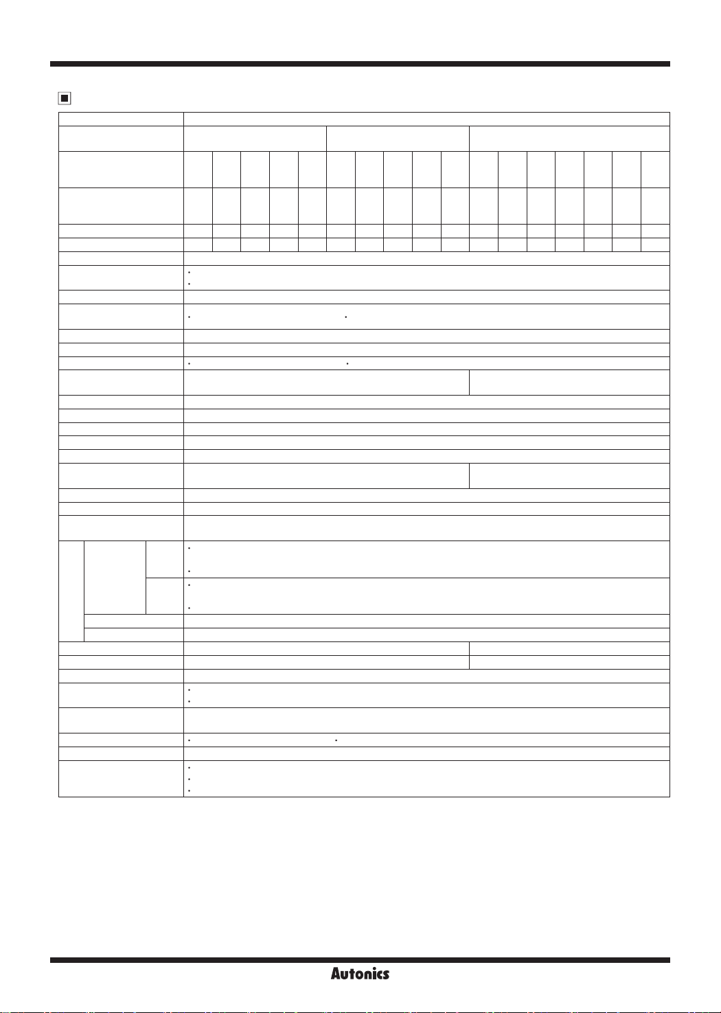
Dimensions
Head type
•
22
DIN43650-A connector type
•
Ø24
22
- .
※1
G3/8
(EN837)
(unit: mm)
115
19 8214.2
5 6
90
※
1
G3/8
(EN837)
□27
24.4
63.2
·
33.2
1
-
. a
:1
46.5
5 6
19
:T
---
DIN43650-A
connector
M12 connector type
•
Ø24
22
DT04-3P connector type
•
Ø24
22
19 20.3
5.6
※
1
G3/8
(EN837)
5 6
19 18.8 19
※
1
G3/8
(EN837)
35.9
46.8
10
Ø21
M12
connector
DT04-3P
connector
@
I
3.4
Ø21
0
Connector: CS-DT3P,
sold separately
Autonics
G-63
TPS30 Series
Dimensions
Cable type
※
1: Pressure port
G1/4
(EN837)
Ø24
15
(unit: mm)
47.6
5.6
19
22
※
1
G3/8
(EN837)
20.3 21.7
R1/2
(DIN3852)
14.3
Ø21
Ø5, 2m
12
NPT1/4
(DIN3852)
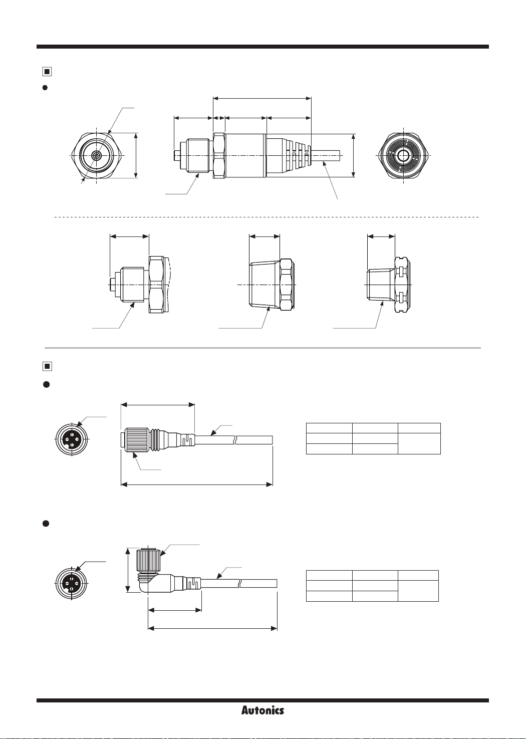
Connection Cable (Sold Separately)
~
CID3-2/CID3-5
•
•
CLD3-2/CLD3-5
•
M12
M12
1
◄
I.
40
Ø5
Ø14.8
L(m)
Ø14.8
Ø5
27.5
u
•
32
I:
L(m)
2 I
.I
•
Model L(m) Material
CID3-2 2
CID3-5 5
※
Only for M12 connector.
Model L(m) Material
CLD3-2 2
CLD3-5 5
I
PVC
PVC
(unit: mm)
G-64
Autonics
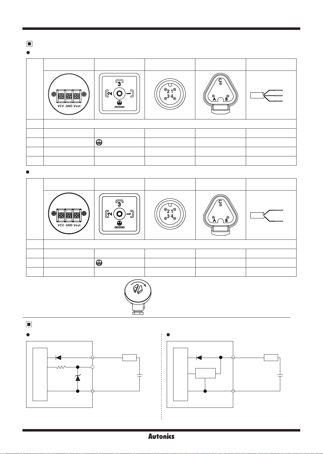
Connectors
Voltage output type
Head type
Non-indicating Pressure Transmitters
DIN43650-A
connector type
M12 connector type
DT04-3P
connector type
Cable type
Pin
type
Func.
Pin
+ + 1 1 A Brown
- -
Vout Vout 2 4 B Black
N.C
-
Current output type
•
Head type
Pin
type
Func.
Pin
+ + 1 1 A Brown
- -
N.C Vout 2, 3 2, 4 B
※
In case of head type, remove the top cover
3 2
DIN43650-A
connector type
.
3 C Blue
- -
M12 connector type
3 C Blue
DT04-3P
connector type
Cable type
-
Brown
Black
Blue
Brown
Blue
Connections
Voltage (1-5VDC) output type
•
Main Circuit
※
Cable color is only for cable type.
(brown) VCC
(black) Voltage
(1-5VDC) Output
(blue) GND
LOAD
+
8-36VDC
Autonics
Current (DC4-20mA) output type
(brown) VCC
Current
amplier
Main Circuit
(blue) GND
LOAD
+
11-36VDC
G-65
TPS30 Series
Troubleshooting
Error Troubleshooting
No outputs
Abnormally uctuating output
Out of zero point output value
Proper Usage
• Follow instructions in 'Cautions during Use'. Otherwise, It may cause unexpected accidents.
• 8-36VDC, 11-36VDC power supply should be insulated and limited voltage/current or Class 2, SELV power supply
device.
• When installing the unit on pipe line, use the hexagon part of connections not to turn the unit with a pipe wrench. Do not
use the unit with strong vibrations.
• Store the unit at the place without moisture, dust, and v bration.
• This product which does not have drive part at sensing part does not need to repair it. Even though inside of pressure
pipe is normally clean, it needs to take maintenance once a year as below instructions.
① Check the broken status of outside.
② Check the pressure slot, cleanliness inside, and corrosion state.
③ Short each terminal and check the insulation resistance between the case and power.
• When removing a sensor for maintenance, follow the below instructions.
①Replace an O-ring which is used once.
②Be sure that diaphragm part is not damaged.
• Switch or circuit breaker for suppling or cutting o the power should be installed nearby users for convenient control.
• The unit cannot be repaired due to disassembled structure.
• The unit is xed with bolt and nut at the both sides of case.
Do not press excessive load (approx. 300kg/cm²), or it may cause damage to the unit.
• This unit may be used in the following environments.
① Indoor / Outdoor (in the environment condition rated in 'Specications')
② Altitude max. 2,000 m
③ Pollution Degree 2
④ Installation Category II
Check the power supply.
Check the polarity (+, -) when wiring the cable.
Check the connection part.
Check the power supply.
Check the supplied pressure.
Check the pressure line.
Check the power supply.
Check the load resistive value of current output type for a receiver is over 700Ω.
(when supplying 24VDC)
Check the measuring point and transmission distance.
Check the line resistance is below 700Ω.
G-66
 Loading...