

DRW170305AD
Autonics
Non-indicating Pressure Transmitters
TPS30 SERIES
I N S T R U C T I O N M A N U A L
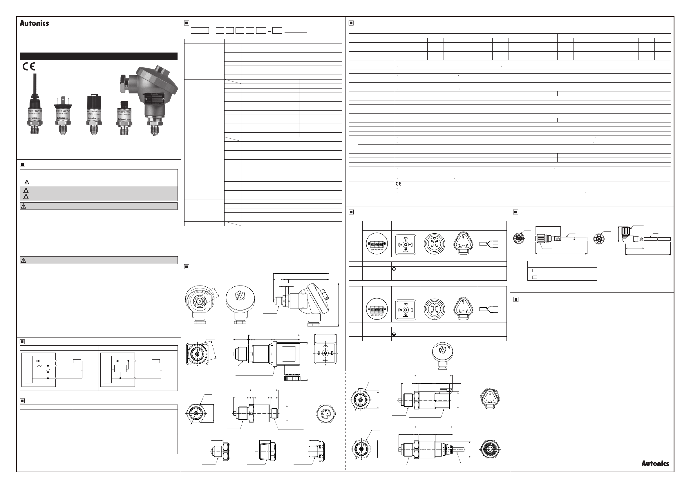
Cable type
Safety Considerations
Please observe all safety considerations for safe and proper product operation to avoid
※
hazards.
symbol represents caution due to special circumstances in which hazards may occur.
※
Warning
Caution
Warning
1. Fail-safe device must be installed when using the unit with machinery that may
cause serious injury or substantial economic loss. (e.g. nuclear power control,
medical equipment, ships, vehicles, railways, aircraft, combustion apparatus, safety
equipment, crime/disaster prevention devices, etc.)
Failure to follow this instruction may result in personal injury, re or economic loss.
2. Do not use the unit in the place where ammable/explosive/corrosive gas, high
humidity, direct sunlight, radiant heat, vibration, impact, or salinity may be present.
Failure to follow this instruction may result in explosion or re.
3. Do not disassemble or modify the unit.
Failure to follow this instruction may result in re or electric shock."
Caution
1. Do not apply beyond the rated pressure.
Failure to follow his instruction may result in product damage.
2. Use the unit within the rated specications.
Failure to follow his instruction may result in re or product damage.
3. Fix the cable through the cable connection part and do not turn the cable of the
unit.
Failure to follow cause instruction may result in product damage.
4. Keep metal chip, dust, and wire residue from owing into the unit.
Failure to follow his instruction may result in re or product damage.
5. Check the polarity of the contact before wiring the unit.
Failure to follow his instruction may result in product damage by a re.
6. This product is designed to detect the pressure of noncorrosive uid. Do not use
for corrosive uid.
Failure to follow his instruction may result in product damage.
7. Use a dry cloth to clean the unit, and do not use water or organic solvent.
Failure to follow his instruction may result in re.
Connections
Voltage (1-5VDC) output type Current (DC4-20mA) output type
Main Circuit
~
※
Cable color is only for cable type.
Troubleshooting
Error Troubleshooting
~~
No outputs
Abnormally uctuating
output
Out of zero point output
value
※
The above specications are subject to change and some models may be discontinued
without notice.
※
Be sure to follow cautions written in the instruction manual and the technical descriptions
(catalog, homepage).
DIN43650-A
Connector type
DT04-3P
Connector type
M12
Connector type
Head type
Thank you for choosing our Autonics product.
Please read the following safety considerations before use.
Failure to follow these instructions may result in serious injury or death.
Failure to follow these instructions may result in personal injury or product damage.
(brown) VCC
(black) Voltage
(1-5VDC) Output
(blue) GND
LOAD
+
8-36VDC
-
J
Current
amplier
Main Circuit
(brown) VCC
(blue) GND
LOAD
7
~
----==-~------=--
Check the power supply.
Check the polarity (+, -) when wiring he cable.
Check the connection part.
Check the power supply.
Check the supplied pressure.
Check the pressure line.
Check the power supply.
Check the load resistive value of current output type for a
receiver is over 700Ω. (when supplying 24VDC)
Check the measuring point and transmission distance.
Check the line resistance is below 700Ω.
_-
_==.J
+
11-36VDC
-
Ordering Information
TPS30
① ② ③ ④ ⑤ ⑥ ⑦ ⑧
①
Item
②
Measurement
pressure
③
Cable
④
Pressure range
⑤
Output type
⑥
Pressure port
⑦
Option
(connector cable)
User pressure range
⑧
※
1: The pressure is sealed gauge pressure. The unit is sealed structure. t is based on atmospheric
pressure 101.3kPa (1 013bar).
※
2: G1/4 is the standard pressure port.
For the other pressure ranges, G3/8, R1/2 are standard pressure ports.
※
The option ports are sold separately. In case of large amount ordering, contact the Autonics for
3:
manufacturing the requested pressure port.
※
4: Only for M12 connector type.
※
5: Write the desired pressure range and it is the default of user pressure range.
(
select " Z" at ④Pre ssure range)
G 2 9 V
-□□□□□-□
Description
TPS30 Pressure Transmitter
G Gauge pressure, sealed gauge pressure
A Absolute pressure
1 Head type
2 DIN43650-A connector type
3 M12 connector type
4 DT04-3P connector type
5 Cable type
---.......____
3 0 to 0.1MPa 0 to 0.1MPa
4 0 to 0.2MPa 0 to 0.2MPa
5 0 to 0.7MPa 0 to 0.7MPa
6 0 to 1MPa 0 to 1MPa
7 0 to 2MPa 0 to 2MPa
※
2
8
※
2
9
※
2
A
※
2
B
※
2
C
※
2
D
※
2
E
F - 0.1 to 0MPa
------
G - 0.1 to 0.1MPa
H - 0.1 to 0.7MPa
J - 0.1 to 1MPa
K - 0.1 to 2MPa
Z Others
V Voltage (1-5VDC) output
A Current (DC4-20mA) output
G8 G3/8 (PF) (EN837)
G4 G1/4 (PF) (EN837)
R2 R1/2 (PT) (DIN3852)
N4 NPT1/4 (DIN3852)
※
3
ZZ
00 Not used
2I "I" type 2m
2L "L" type 2m
※
4
5I "I" type 5m
5L "L" type 5m
------
G8 00
Gauge pressure Absolute pressure
0 to 3.5M Pa
0 to 5MPa
0 to 10MPa
0 to 20MPa
0 to 40MPa
0 to 50MPa
0 to 60MPa
Sealed gauge pressure
Others (option)
User pressure range
Dimensions
● Head type
22
G3/8
(EN837)
● DIN43650-A connector type
Ø24
·~
● M12 connector type
22
Ø24
.@fil
22
※
1: Pressure port
15
~
G1/4
(EN837)
19
,..---.,..,.
※
1
G3/8
(EN837)
DIN43650-A connector
19
~
※
1
G3/8
(EN837)
24.4
5.6
~_______.,...-
35.9
5.6
20.3 10
o==iir---------'
14 3
-fl
R1/2
(DIN3852)
(0 to 0.5MPa)
-
-
-
-
-
-
1
14.2
33 2
Ø21
5.6
-
115
1
:
-----.
NPT1/4
DIN3852)
(
※
※
5
19 82
※
1
63.2
"l==========,!~B
M12 connector
※
1
(unit: mm)
□27
ffi
46 5
@ i
I
12
~
Specications
Series TPS30
Pressure type Gauge pressure, absolute pressure Sealed gauge pressure
Rated pressure range (MPa)
Expanded analog output
range (MPa)
Max. pressure range (MPa)
Burst pressure (MPa) 0.6 0.6 3 3 3 0.6 0.6 3 3 3 15 30 75 120 160 160 160
Measured materials Liquid, gas, oil
Power supply
Permissible voltage range
Current consumption
Response ime Max. 1ms
Protection circuit Reverse polarity protection circuit
Output type
Compensation temperature
Accuracy Max. ±0.5% F.S. (including linearity, hysteresis, reproducibility)
Linearity Max. ±0.2% F.S.
Hysteresis Max. ±0.2% F.S.
Temp. Zero Shift Max. ±0.1% F.S./10℃ (standard), max. ±0.25% F.S /10℃ (max.)
Temp. Span Shift Max. ±0.1% F.S./10℃ (standard), max. ±0.25% F.S /10℃ (max.)
Temperature characteristics
Load resistance Current output type: max. 700Ω (supplying 24VDC)
Dielectric strength 500VAC 50/60Hz for 1 minute
Insulation resistance Over 100MΩ (at 500VDC megger)
Environ-
Vibration
Shock
Tightening torque Max. 10N.m
Protection structure
Material Stainless steel 316L (head component of head type: aluminium diecasting), connector: Polybutylene terephthalate G30, water-proof rubber: Silicon
Connection
Approval
Weight
※
1: The sensor is sealed structure. It is based on atmospheric pressure 101.3kPa (1.013bar).
※
Environment resistance is rated at no freezing or condensation.
Voltage output
Ambient
I
temp.
I
Current output
Ambient humidity
ment
Fluid temp.
※
2
0 to 0.1 0 to 0.2 0 to 0.7 0 to 1 0 to 2 -0.1 to 0
0 to 0.11 0 to 0.22 0 to 0.77 0 to 1.1 0 to 2.2
0.6 0.6 3 3 3 0.6 0.6 3 3 3 10 20 50 80 120 120 120
Voltage output type: 8-36VDCᜡ (ripple P-P: max. 10%) Current output type: 11-36VDCᜡ (ripple P-P: max. 10%)
90 to 110% of rated voltage
Voltage output type: max. 20mA Current output type: max. 30mA
Voltage output type: 1-5VDCᜡ Current output type: DC4-20mA
-10 to 80℃ 0 to 80℃
-
Head type, D N43650-A connector type, M12 connector type, DT04-3P connector type: -40 to 125℃, storage: -40 to 125℃ Cable type: -40 to 80℃, storage: -40 to 80℃
Head type, D N43650-A connector type, M12 connector type, DT04-3P connector type: -40 to 85℃, storage: -40 to 125℃ Cable type: -40 to 80℃, storage: -40 to 80℃
35 to 85%RH
-40 to 125℃
10g, 20 to 2,000Hz 20g, 20 to 2,000Hz
100g/6ms 500g/1ms
Head type, M12 connector type, DT04-3P connector type, cable type: IP67 (IEC standard) DIN43650-A connector type: IP65 (IEC standard)
Voltage output type: +, -, Vout Current output type: +, -
CE
Head type: approx. 330g (approx. 250g)
DIN43650-A connector type, M12 connector type, DT04-3P connector type: approx. 130g (approx. 50g) Cable type: approx. 200g (approx. 120g)
-0.1 to
0 01
-0.1 to 0.1 -0.1 to 0.7
-0.1 to
0.12
Connector
● Voltage output type
~-------r-~-------,----------,---~
Head type
Pin
type
Function
Pin
+ + 1 1 A Brown
- Vout Vout 2 4 B Black
-
N C
● Current output type
Head type
Pin
90
type
Function
Pin
+ + 1 1 A Brown
- N.C Vout 2, 3 2, 4 B
※
In case of head type, remove the top cover
::
---
● DT04-3P connector type
Ø24
~
● Cable type
:
00
Ø24
22
22
DIN43650-A
connector type
3 2
DIN43650-A
connector type
@
i----
5.6
19
※
1
G3/8
DT04-3P connector
(EN837)
5.6
19
※
1
G3/8
(EN837)
M12 connector
type
3 C Blue
M12 connector
type
3 C Blue
.
DT04-3P
connector type
- -
DT04-3P
connector type
Cable type
Cable type
-
~
-
~-------+j
46.8
18 8 19 3.4
47 6
20.3 21.7
__
Ø21
Connector: CS-DT3P,
sold separately
Ø21
Ø5, 2m
__J
Brown
Black
Blue
Brown
Blue
※
1
-0.1 to 1 -0.1 to 2 0 to 3.5 0 to 5 0 to 10 0 to 20 0 to 40 0 to 50 0 to 60
-0.1 to
-0.1 to
0.78
1.11
※
2: The weight includes packaging. The weight in parentheses is for unit only.
Connection Cable (sold separately)
~
● CID3-2/CID3-5 ● CLD3-2/CLD3-5
M12
Model L(m) Meterial
C D3-2 2
D3-5 5
C
※
Only for M12 connector.
Gauge pressure
-0.1 to
0 to 3.85 0 to 5.5 0 to 11 0 to 22 0 to 44 0 to 55 0 to 66
2.21
I
I
-25 to 100℃: max. ±1.5% F.S. / -40 to 125℃: max. ±2.5% F.S.
I
I
40
Ø5
Ø14 8
L (m)
PVC
M12
27.5
32
Cautions during Use
1. Follow instruc ions in 'Cautions during Use'. Otherwise, It may cause unexpected accidents.
2. 8-36VDC, 11-36VDC power supply should be insulated and limited voltage/current or Class
2, SELV power supply device.
3. When installing the unit on pipe line, use the hexagon part of connections not to turn the
unit with a pipe wrench. Do not use the unit with strong vibrations.
4. Store the unit at he place without moisture, dust, and vibration.
5. This product which does not have drive part at sensing part does not need to repair it. Even
though inside of pressure pipe is normally clean, it needs to take maintenance once a year
as below instructions.
① Check the broken status of outside.
② Check the pressure slot, cleanliness inside, and corrosion state.
③ Short each terminal and check the insula ion resistance between he case and power.
6. When removing a sensor for maintenance, follow he below instructions.
①Replace an O-ring which is used once.
②Be sure hat diaphragm part is not damaged.
7. Switch or circuit breaker for suppling or cut ing o the power should be installed nearby
users for convenient control.
8. The unit cannot be repaired due to disassembled structure.
9. The unit is xed with bolt and nut at he bo h sides of case.
Do not press excessive load (approx. 300kg/cm²), or it may cause damage to the unit.
10.This unit may be used in the following environments.
① Indoor / Outdoor (in the environment condition rated in 'Specica ions')
② Al itude max. 2,000 m
③ Pollu ion Degree 2
④ Installation Category II
(unit: mm)
Ø14.8
Ø5
L (m)
Autonics
 Loading...