

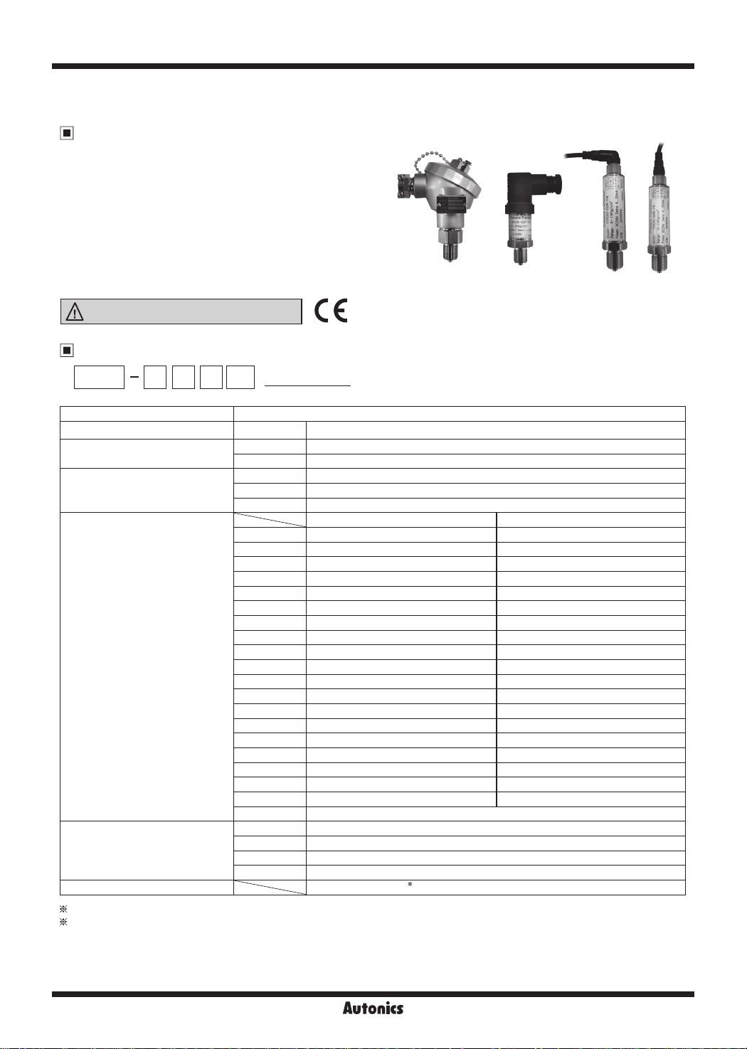
TPS20 Series
Non-indicating Pressure Transmitters
Features
•
Excellent corrosion resistance with stainless steel
housing
•
High accuracy ±0.3% F.S.
•
Various connection method
- Head type, DIN connector type, connector cable type
•
Various user friendly function
- Built-in zero-point, span adjustment (head type)
Please read “Safety Considerations”
in the instruction manual before using.
Ordering Information
[Head type] [DIN connector type] [Connector cable type]
TPS20
~I-DD
G 1 5
F8
□□--
(0 to 5kgf/cm2)
① ② ③ ④ ⑤ ⑥
Non-indicating Pressure Transmitters
① Item
② Measurement presssure
③ Cable
④ Pressure range
⑤ Pressure port
⑥ User pressure range
1: Write the desired pressure range and it is the default of user pressure range. (
For ordering cable, order as CID3-2, CID3-5, CLD3-2, CLD3-5. (sold separately)
TPS20 Pressure Transmitter
G Gauge pressure
A Absolute pressure
1 Head type
2 DIN connector type
3 Connector cable type
Gauge pressure Absolute pressure
1 0 to 0.2kgf/cm
---------------
2 0 to 0.5kgf/cm
3 0 to 1kgf/cm2 0 to 1kgf/cm2
4 0 to 2kgf/cm
5 0 to 7kgf/cm
6 0 to 10kgf/cm
7 0 to 20kgf/cm
8 0 to 35kgf/cm2 0 to 35kgf/cm2
9 0 to 70kgf/cm
A 0 to 100kgf/cm
C 0 to 200kgf/cm2
F 0 to 300kgf/cm2
H 0 to 350kgf/cm2
M -760mmHg to 0kgf/cm2
O -760mmHg to 1kgf/cm2
Q -760mmHg to 7kgf/cm2
V -760mmHg to 10kgf/cm2
X -760mmHg to 20kgf/cm2
Y -760mmHg to 35kgf/cm
Z Others
P2 R1/2 (with adapter, PT)
P8 R3/8 (with adapter, PT)
F8 G3/8 (standard, PF)
ZZ Others
User pressure range
2
2
2
0 to 2kgf/cm2
2
0 to 7kgf/cm
2
2
0 to 20kgf/cm
2
2
2
1
*
------------
-
-
2
0 to 10kgf/cm2
-
-
-
-
-
-
-
-
-
-
-
select "Z" at ④Pressure range)
2
Autonics
G-67
Non-indicating Pressure Transmitters
Specifications
Series TPS20
Pressure type Gauge pressure Absolute pressure Compound pressure
Rated pressure range 0 to 0.2 to 350kgf/cm
Max. pressure range 300% of max. span
Measured materials Liquid, gas, oil (except corrosive environment of stainless steel type 316)
Power supply 15-35VDCᜡ
Permissible voltage range 90 to 110% of rated voltage
Current consumption Max. 50mA
Response time Max. 100ms
Protection circuit Reverse polarity protection circuit
Current output DC4-20mA
Linearity ±0.3% F.S. (-10 to 50℃), ±0.5%F.S. (50 to 70℃)
Hysteresis ±0.3% F.S.
Temp. Zero Shift ±0.03% F.S.
Temp. Span Shift ±0.03% F.S. (at 25℃)
Load resistance Max. 600Ω
Insulation resistance Over 100MΩ (at 500VDC megger)
Dielectric strength 500VAC 50/60Hz for 1 minute
Vibration 1.5mm amplitude at frequency of 10 to 55Hz (for 1 min) in each X, Y, Z direction for 2 hours
Shock 95m/s
Tightening torque Industrial plug over 5N
Pressure port G3/8t (standard), R3/8, R1/2
Environment
Materials Sealing, diaphragm, connection: stainless steel type 316, O-ring: uoro rubber
Connection +, -
Case structure Drip-proof structure
Approval
Weight
※
1: The weight includes packaging. The weight in parenthesis is for unit only.
※
F.S.(Full Scale): It is rated pressure range.
※
Environment resistance is rated at no freezing or condensation.
Ambient temp. -10 to 70℃, storage: -10 to 70℃
I
Ambient humi. 5 to 95% RH, storage: 5 to 95% RH
I
※
1
2
ᜢ
Approx. 350g (approx. 320g) (based on head type)
2
I
0 to 1.0 to 35kgf/cm
I
2
I
-760mmHg to 0 to 35kgf/cm
I
2
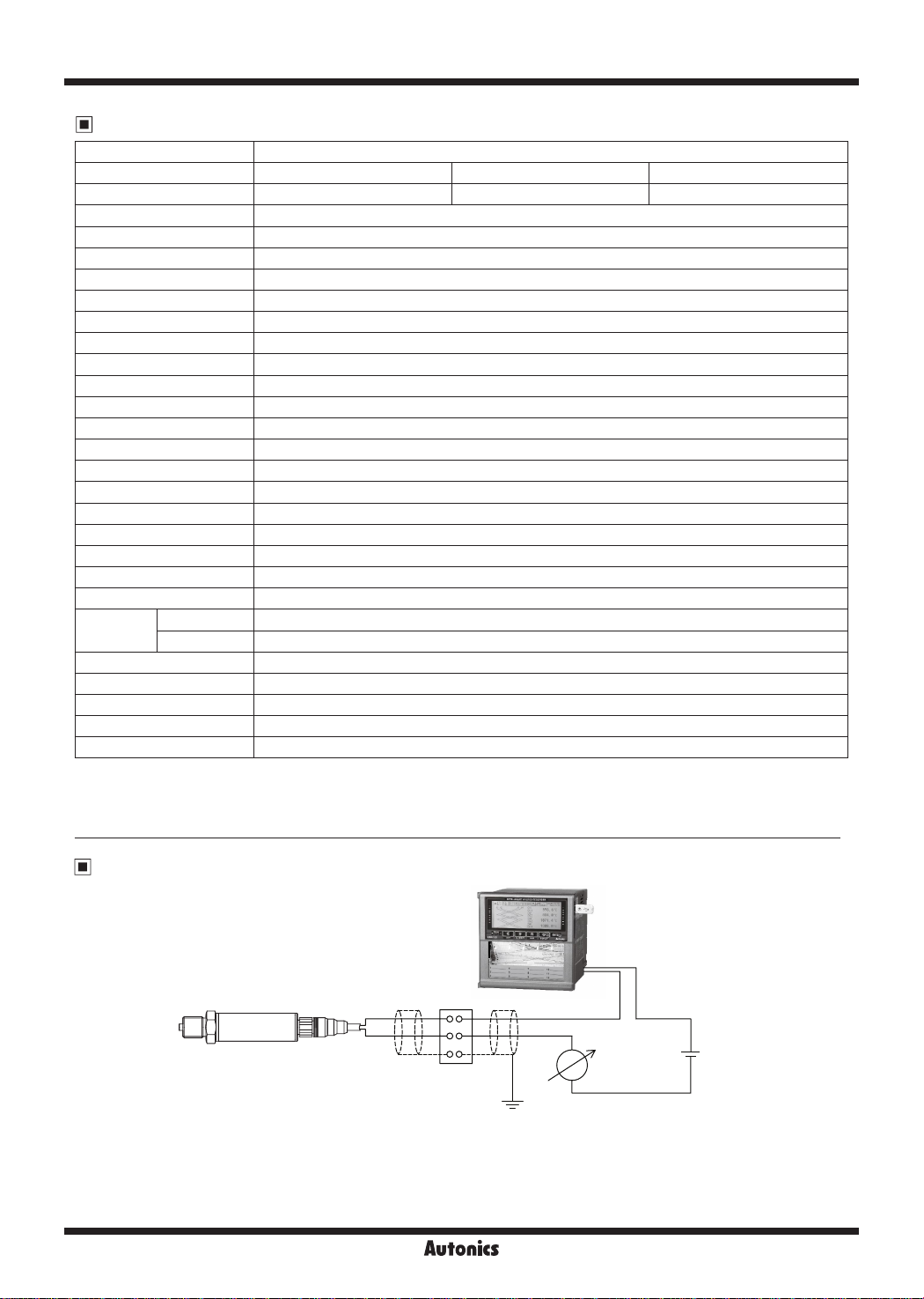
Example of External Connections
TPS20
G-68
+
-
Terminal
Autonics
KRN100
+
-
+
DC4-20mA
Power 24VDC load 600Ω
Output DC4-20mA 2-wire
+
-
24VDC

TPS20 Series
Dimensions
● Head type
● DIN connector type
● Connector cable type
24
27
22
106
34
21 14
G3/8
31 28 42
21
8
G3/8
31 62 10
21
8
71
104
(unit: mm)
84
46.5
※
The standard pressure port for above is G3/8.
Connection Cable (Sold Separately)
● CID3-2 / CID3-5
27.5
40
Ø14.8
I:
L(m)
Ø14.8
32
L(m)
· . I
Ø5
.I
Ø5
M12
● CLD3-2 / CLD3-5
M12
Model L (m) Meterial
CID3-2 2
CID3-5 5
Model L (m) Meterial
CLD3-2 2
CLD3-5 5
PVC
PVC
M12 ConnectorG3/8
(unit: mm)
Autonics
G-69

Non-indicating Pressure Transmitters
Connectors
Head type DIN connector type Connector cable type
Pin
+
※
In case of head type, remove the top cover
Connections
~
~
Main Circuit
-
0
2
.
~
~
Current amplier
c-
-
Pin Func.
1 + 1 +
+
,;:-
15-35VDC
-
2
3 N.C 3 F.G.
F.G. 4
(brown) +V
=
....
. l
..
'.v
I
l
..
(blue) GND
Pin Func.
2 N.C
Troubleshooting
Error Troubleshooting
No outputs
Abnormally uctua ing output
Out of zero point output value
Check the power supply.
Check the polarity (+, -) when wiring cable.
Check the connection part.
Check the power supply.
Check the supplied pressure.
Check the pressure line.
Check the power supply.
Check the load resistive value of current output type for a receiver is over 600Ω.
Check the measuring point and transmission distance.
Check the line resistance is below 600Ω.
Proper Usage
• Follow instructions in 'Cautions during Use'. Otherwise, It may cause unexpected accidents.
• 15-35VDC power supply should be insulated and limited voltage/current or Class 2, SELV power supply device.
• When installing the unit on pipe line, use the hexagon part of connections not to turn the unit with a pipe wrench. Do not use the
unit with strong vibrations.
• Store the unit at the place without moisture, dust, and v bration.
• This product which does not have drive part at sensing part does not need to repair it. Even though inside of pressure pipe is
normally clean, it needs to take maintenance once a year as below instructions.
① Check the broken status of outside.
② Check the pressure slot, cleanliness inside, and corrosion state.
③ Short each terminal and check the insulation resistance between the case and power.
• When removing a sensor for maintenance, follow the below instructions.
①Replace an O-ring which is used once.
②Be sure that diaphragm part is not damaged.
• Switch or circuit breaker for suppling or cutting o the power should be installed nearby users for convenient control.
• The unit cannot be repaired due to disassembled structure.
• The unit is xed with bolt and nut at the both sides of case.
Do not press excessive load (approx. 300kg/cm²), or it may cause damage to the unit.
• This unit may be used in the following environments.
① Indoor / Outdoor (in the environment condition rated in 'Specications')
② Altitude max. 2,000 m
③ Pollution Degree 2
④ Installation Category II
G-70
Autonics
 Loading...