

DRW171430BA
KRN100
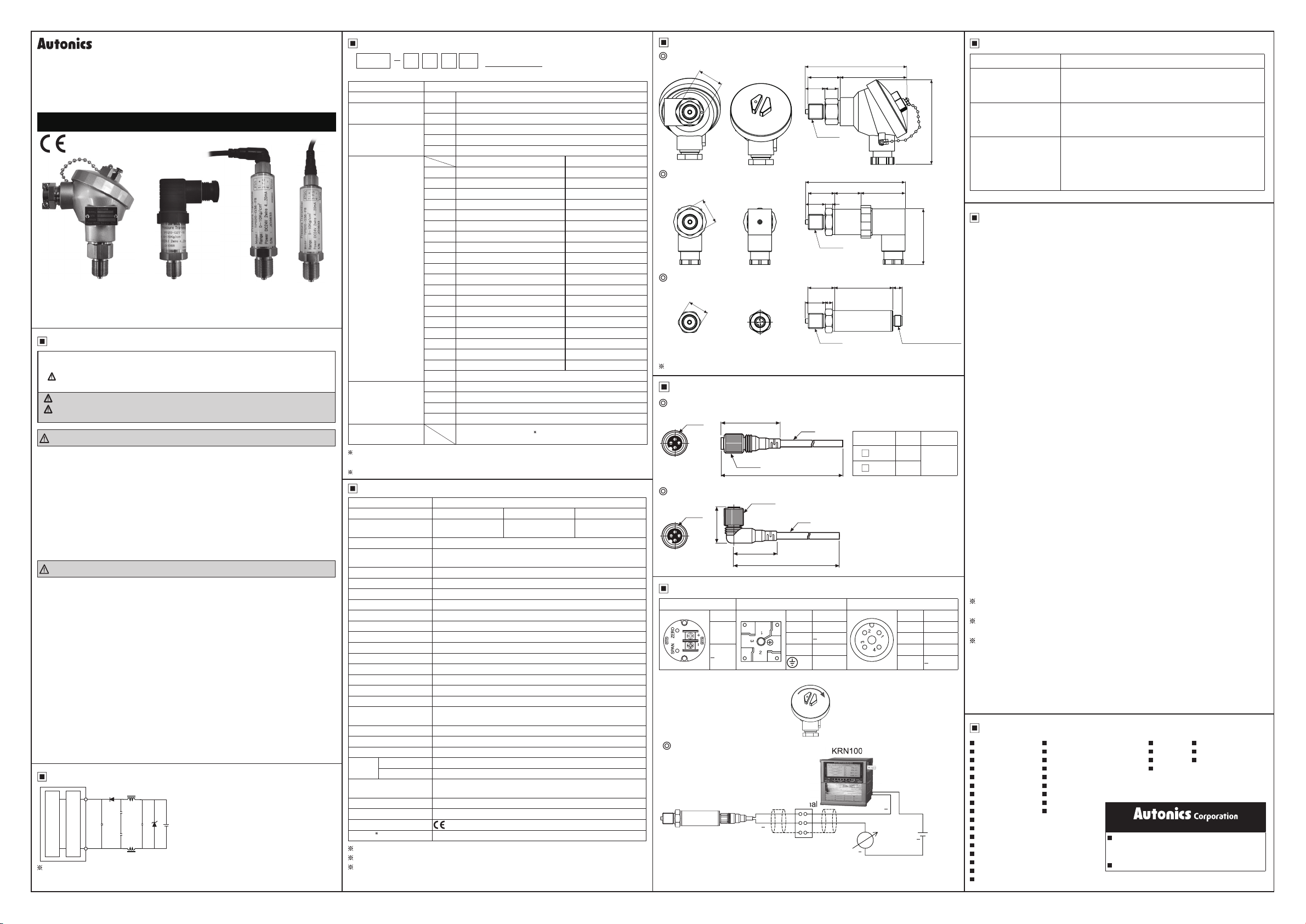
Pressure Transmitter
TPS20 SERIES
I N S T R U C T I O N M A N U A L
Head type DIN connector type Connector cable type
Please read the following safety considerations before use.
Safety Considerations
※
Please observe all safety considerations for safe and proper product
operation to avoid hazards.
symbol represents caution due to special circumstances in which hazards
※
may occur.
Warning
Caution
damage.
Warning
1. Fail-safe device must be installed when using the unit with machinery that
may cause serious injury or substantial economic loss. (e.g. nuclear
power control, medical equipment, ships, vehicles, railways, aircraft,
combustion apparatus, safety equipment, crime/disaster prevention
devices, etc.)
Failure to follow this instruction may result in personal injury, fi re, or economic loss.
2. Do not use the unit where fl ammable or explosive gas, humidity, direct
sunlight, radiant heat, vibration and impact may be present.
Failure to follow this instruction may result in fi re or explosion.
3. Do not disassemble or modift the unit. Please contact us if necessary.
Failure to follow this instruction may result in fi re.
Caution
1. Do not apply beyond rated pressure.
Failure to follow this instruction may result in product damage.
2. Use the unit within the rated specifi cations.
Failure to follow this instruction may result in fi re or shortening the life cycle of the
unit.
3. Fix the cable through the cable connection part.
Do not turn the cable of the unit.
Failure to follow this instruction may result in product damage.
4. Keep dust and wire residue from fl owing into the unit.
Failure to follow this instruction may result in burn out of the unit.
5. Check the polarity of the measurement terminals before wiring the unit.
Failure to follow this instruction may result in burn out of the unit.
6. Please contact us for using the unit to the corrosive detergent.
Failure to follow this instruction may result in shortening the life cycle of the unit
or product damage.
7. Do not use water or oil-based detergent when cleaning the unit. Use dry
cloth to clean the unit.
Failure to follow this instruction may result in or fi re.
Connections
Main Circuit
The above specifications are subject to change and some models
may be discontinued without notice.
Thank you for choosing Autonics product.
Failure to follow these instructions may result in serious injury or death.
Failure to follow these instructions may result in personal injury or product
(brown) +V
+
15-35VDC
-
Current amplifi er
(blue) GND
Ordering Information
TPS20
G 1 5
F8
(0 to 5kgf/cm
① ② ③ ④ ⑤ ⑥
Description
①Item
②Measurement
presssure
TPS20 Pressure Transmitter
G Gauge pressure
A Absolute pressure
1 Head type
③Cable
2 DIN connector type
3 Connector cable type
Gauge pressure Absolute pressure
1 0 to 0.2kgf/cm
2 0 to 0.5kgf/cm
3 0 to 1kgf/cm2 0 to 1kgf/cm2
4 0 to 2kgf/cm
5 0 to 7kgf/cm
2
2
6 0 to 10kgf/cm
7 0 to 20kgf/cm
8 0 to 35kgf/cm2 0 to 35kgf/cm2
9 0 to 70kgf/cm
④Pressure range
A 0 to 100kgf/cm
C 0 to 200kgf/cm2
F 0 to 300kgf/cm2
H 0 to 350kgf/cm2
M -760mmHg to 0kgf/cm2
O -760mmHg to 1kgf/cm2
Q -760mmHg to 7kgf/cm2
V -760mmHg to 10kgf/cm2
X -760mmHg to 20kgf/cm2
Y -760mmHg to 35kgf/cm
Z Others
P2 PT 1/2 (with adapter)
⑤Pressure port
P8 PT 3/8 (with adapter)
F8 PF 3/8 (Standard)
ZZ Others
⑥User pressure
range
User pressure range
1: Write the desired pressure range and it is the default of user pressure range.
(
Select "Z" at ④Pressure range)
For ordering cable, order as CID3-2, CID3-5, CLD3-2, CLD3-5.(Sold seperately)
2
)
2
2
-
-
0 to 2kgf/cm2
0 to 7kgf/cm
2
2
0 to 20kgf/cm
2
2
0 to 10kgf/cm2
-
-
-
-
-
-
-
-
-
-
2
-
1
2
2
Specifi cations
Series TPS20
Pressure type Gauge pressure Absolute pressure
Rated pressure range
0 to
0.2 to 350 kg/cm
0 to
2
1.0 to 35 kg/cm
Max. pressure range 300% of max. span
Measured materials
Liguid, Gas, Oil (except corrosive environment of
Stainless steel type 316)
Power supply 15-35VDCᜡ
Permissible voltage range
90 to 110% of rated voltage
Current consumption Max. 50mA
Response time Max. 100 ms
Protection circuit Reverse polarity protection circuit
Current output DC4-20 mA
Linearity ±0.3% F.S.(-10 to 50 ℃), ±0.5%F.S.(50 to 70 ℃)
Hysteresis ±0.3% F.S.
Temp. Zero Shift ±0.03% F.S.
Temp. Span Shift ±0.03% F.S. (at 25 ℃)
Load resistance Max. 600 Ω
Insulation resistance Over 100MΩ (at 500VDC megger)
Dielectric strength 500VAC 50/60Hz for 1 minute
Vibration
Shock 95m/s
1.5mm amplitude at frequency of 10 to 55Hz(for 1 min) in
each X, Y, Z direction for 2hours
2
Tightening torque Industrial plug over 5N
Pressure port PF 3/8(standard), PT 3/8, PT 1/2
Environment
Materials
Ambient temp.
Ambient humid.
-10 to 70 ℃, storage: -10 to 70 ℃
5 to 95% RH, storage: 5 to 95% RH
Sealing, Diaphragm, Connection: Stainless steel type 316,
O-ring: fl uoro rubber
Connection +, Case structure Drip-proof structure
Approval
1
Weight
Approx. 350 g (approx. 320 g) (based on head type)
1: The weight includes packaging. The weight in paranthesis is for unit only.
F.S.(Full Scale): It is rated pressure range.
Environment resistance is rated at no freezing or condensation.
Compound pressure
-760 mmHg to
2
0 to 30 kg/cm
2
Dimensions
Head type
24
106
34 71
21 14
G3/8
DIN connector type
104
31 28 42
21
27
8
G3/8
Connector cable type
22
31 62 10
21
8
G3/8
M12 Connector
The standard pressure port for above is G3/8.
Connection Cable (sold separately)
CID3-2 / CID3-5
M12
40
Ø5
Model L(m) Meterial
C
C
D3-2 2
D3-5 5
CLD3-2 / CLD3-5
M12
Ø14.8
L(m)
Ø14.8
Ø5
27.5
32
L(m)
Connections
Head type DIN connector type Connector cable type
Pin Pin Function Pin Function
+
※
In case of head type, remove the top cover
Example of external connections
TPS20
1 + 1 +
2
3 N.C 3 F.G.
F.G. 4
.
KRN100
Terminal
+
+
DC4-20mA
Power 24VDC load 600Ω
Output DC4-20mA 2 wire
2 N.C
+
+
(unit: mm)
84
46.5
(unit: mm)
PVC
24VDC
Troubleshooting
Error Troubleshooting
Check the power supply.
No outputs
Check the polarity (+, -) when wiring cable.
Check the connection part.
Abnormally fl uctuating
output
Check the power supply.
Check the supplied pressure.
Check the pressure line.
Check the power supply.
Out of zero point output
value
Check the load resistive value of current output type
for a receiver is over 600Ω.
Check the measuring point and transmission distance.
Check the line resistance is below 600Ω.
Cautions during Use
1. When installing the unit on pipe line, use the hexagon part of connections not
to turn the unit with a pipe wrench. Do not use the unit with strong vibrations.
2. The unit is manufactured with precisely. If you drop or shock the unit, it may
lose the function. Please treat the unit carefully.
3. Store the unit at the place without moisture, dust, and vibration.
4. This product which does not have drive part at sensing part does not need to
repair it. Even though inside of pressure pipe is normally clean, it needs to take
maintenance once a year as below instructions.
① Check the broken status of outside.
② Check the pressure slot, cleanliness inside, and corrosion state.
③ Short each terminal and check the insulation resistance between the case
and power. (at 100VDC, over 10MΩ)
④ Check zero, span adjustment and linearity by pressure standards.
5. When removing a sensor for maintenance, follow the below instructions.
① Replace an O-ring which is used once.
② Be sure that diaphragm part is not damaged.
6. In case of head type for connecting the power, use a crimp terminal.
(M3.5, Max. 7.2mm)
7. The connection of this unit should be separated from the power line and high
voltage line in order to prevent inductive noise.
8. Install a power switch or a circuit breaker to supply or cut off the power.
9. Connect the power with the crimp terminals.
10. Switch or circuit breaker should be installed nearby users for convenient
control.
11. Do not use the unit near the high frequency instruments (high frequency
welding machine & sewing machine, large capacity SCR controller).
12. The unit cannot be repaired due to disassembled structure.
13. The unit is fi xed with bolt and nut at the both sides of case.
Do not press excessive load (approx. 300kg/cm
2
), or it may cause damage to
the unit.
14. Do not pull the cables with over 30N of tension force.
15. Tighten the cable connection part fi rmly not to enter water to the cable.
16. Installation environment.
① Indoor / Outdoor
② Altitude max. 2,000 m
③ Pollution degree 2
④ Installation category II
We are not responsible for any damages and claims for careless.
Must read the cautions for your safety and using.
If there are any problems with the unit, contact the head offi ce or A/S
center.
Failure to follow these instructions may result in product damage.
Major Products
Photoelectric Sensors Temperature Controllers
Fiber Optic Sensors Temperature/Humidity Transducers
Door Sensors SSRs/Power Controllers
Door Side Sensors Counters
Area Sensors Timers
Proximity Sensors Panel Meters
Pressure Sensors Tachometer/Pulse(Rate) Meters
Rotary Encoders Display Units
Connectors/Sockets Sensor Controllers
Switching Mode Power Supplies
Control Switches/Lamps/Buzzers
I/O Terminal Blocks & Cables
Stepper Motors/Drivers/Motion Controllers
Graphic/Logic Panels
Field Network Devices
Laser Marking System(Fiber, Co₂, Nd: YAG)
Laser Welding/Cutting System
HEADQUARTERS:
18, Bansong-ro 513beon-gil, Haeundae-gu, Busan,
South Korea, 48002
TEL: 82-51-519-3232
E-mail: sales@autonics.com
Recorders Thyristor Units
Indicators Pressure Transmitters
Converters Temperature Transmitters
Controllers
http://www.autonics.com
DRW17143 0B A
 Loading...