

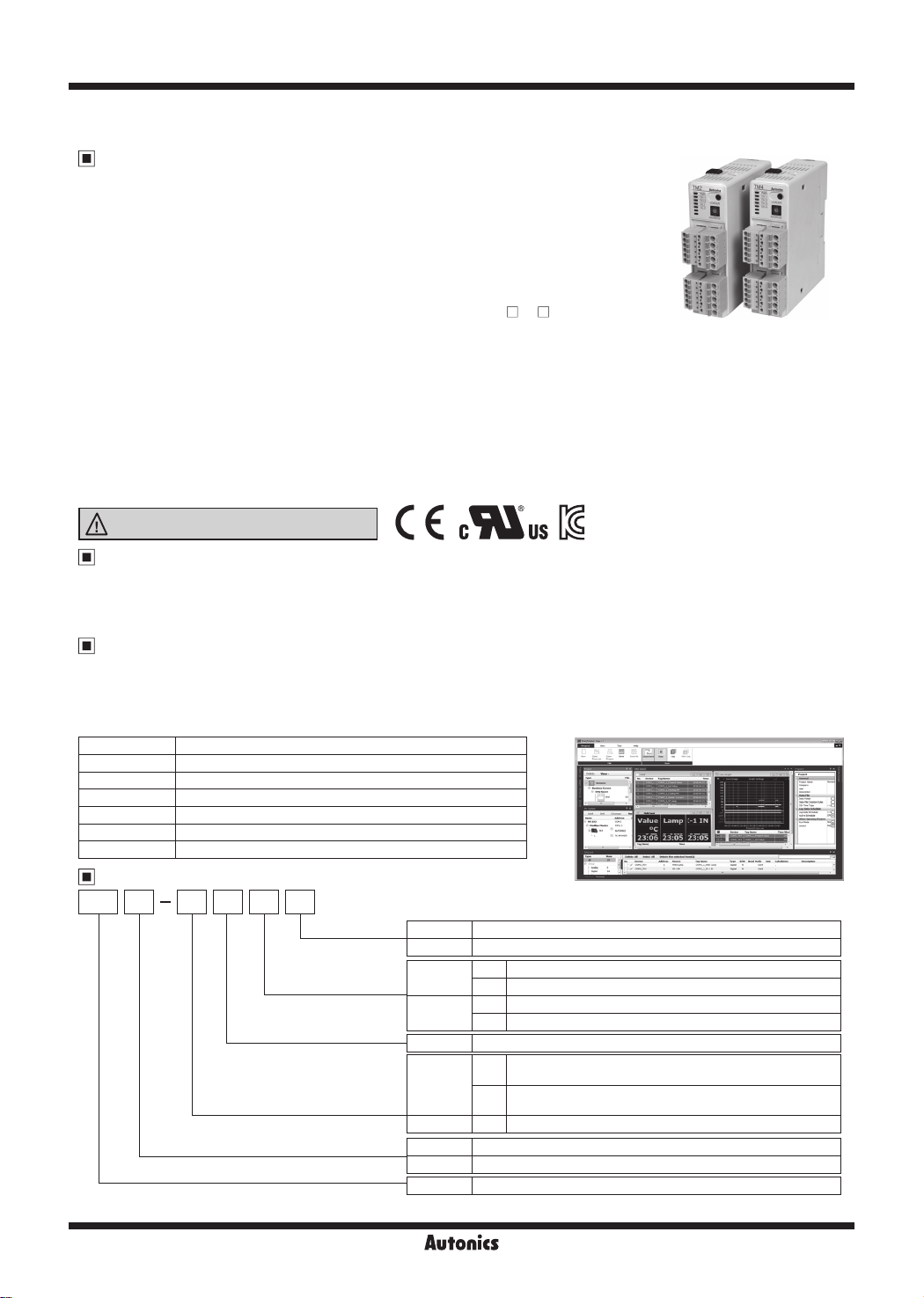
TM Series
2/4-CH Modular Type, PID Control Temperature Controller
Features
● Multi-channel (4-channel: TM4 / 2-channel: TM2) input and output control
● High-speed sampling cycle (4-channel: 100 ms / 2-channel: 50 ms)
● Module connection and expansion with expansion connectors
- Communication between modules
- No additional power supply wiring
- Expandable up to 31 units (124-channel / 62-channel)
● Simultaneous heating and cooling control function
● Isolated input channels (dielectric strength: 1000 VAC)
● Switch between current output and SSR drive output (TM2- 2C models)
● SSR drive output (SSRP function) control options: ON/OFF control, cycle control, phase control
● Parameter conguration via PC (USB and RS485 communication)
- DAQMaster software included (comprehensive device management software)
-
Communication converter sold separately: SCM-WF48 (Wi-Fi to RS485·USB wireless communication converter),
SCM-US48I (USB to RS485 converter), SCM-38I (RS232C to RS485 converter),
SCM-US (USB to serial converter)
● Easy wiring and maintenance with various connectors:
sensor input connector, control output connector, power/communication connector
● Heater disconnect alarm function (CT input)
- Current transformer (CT) sold separately: CSTC-E80LN, CSTC-E200LN, CSTS-E80PP
● Various input types and temperature ranges
Please read “Safety Considerations”
in the instruction manual before using.
Manual
● Visit our website (www.autonics.com) to download user manual and communication manual.
● User manual describes for specications and function, and communication manual describes for RS485 communication
(Modbus RTU protocol) and parameter address map data.
Comprehensive Device Management Program
● DAQMaster is comprehensive device management program for convenient management of parameters and multiple
device data monitoring.
● Visit our website (www.autonics.com) to download user manual and comprehensive device management program.
Item Minimum requirements
System IBM PC compatible computer with Intel Pentium Ⅲ or above
Operations
Memory 256MB+
Hard disk 1GB+ of available hard disk space
VGA Resolution: 1024×768 or higher
Others RS-232 serial port (9-pin), USB port
Ordering Information
Microsoft Windows 98/NT/XP/Vista/7/8/10
(DAQMaster)
< DAQMaster screen >< Computer specication for using software >
TM 4 N 2 R B
Module type
Control output
Power supply
Option I/O
Channels
Item
※
The expansion module does not supply power/comm. terminal. Order it with the basic module.
B Basic module
E Expansion module
2CH
4CH
2 24VDC
2CH
4CH N RS485 comm. output
2 2-channel
4 4-channel
TM Multi-channel modular temperature controller
R Relay output
C Current or SSR drive output selectable
R Relay output
S SSR drive output
CT input, Digital input (DI-1, DI-2),
2
Alarm output 1+2, RS485 comm. output
CT input, Digital input (DI-1, DI-2),
4
Alarm output 1+2+3+4, RS485 comm. output
※
1
J-52
2/4-CH Modular Type, PID Control
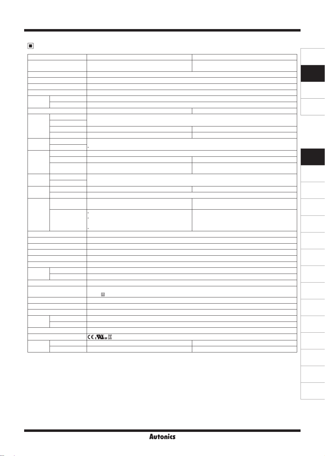
Specifications
Series
No. of channels
Power supply 24VDC
Permissible voltage range 90 to 110% of rated voltage
Power consumption Max. 5W (for max. load)
Display method None- parameter setting and monitoring is available at external devices (PC, PLC, etc.)
Input type
Thermocouple K(CA), J(IC), E(CR), T(CC), B(PR), R(PR), S(PR), N(NN), C(TT), G, (TT), L(IC), U(CC), Platinel II
RTD JPt100Ω, DPt100Ω (permissible line resistance max. 5Ω)
Sampling period 50ms (2 channel synchronous sampling) 100ms (4 channel synchronous sampling)
Thermocouple
Measured
accuracy
RTD
CT input ±5% F.S. ±1-digit max.
Current output ±1.5% F.S. ±1-digit max.
Inuence
of temp.
Thermocouple
※
2
RTD
Relay 250VACᜠ 3A, 30VDCᜡ 3A, 1a
Control
output
Control
method
Option
output
SSR Max. 12VDCᜡ ±3V 30mA Max. 22VDCᜡ ±3V 30mA
Current
Heating, Cooling
Heating&Cooling
Alarm 250VACᜠ 3A 1a
Communication RS485 communication output (Modbus RTU method)
CT input
Option
input
Digital input
Hysteresis 1 to 100℃/℉ (0.1 to 100℃/℉) variable
Proportional band (P) 0.1 to 999.9℃/
Integral time (I) 0 to 9999 sec
Derivative time (D) 0 to 9999 sec
Control period (T) 0.1 to 120.0 sec (only for relay output, SSR drive output)
Manual reset 0.0 to 100.0%
Relay
life cycle
Mechanical Min. 10,000,000 operations
Electrical Min. 100,000 operations (250VAC 3A resistance load)
Insulation resistance Over 100MΩ (at 500VDC megger)
Insulation type
Dielectric strength 1,000VAC 50/60Hz for 1 min (between input terminals and power terminals)
Vibration 0.75mm amplitude at frequency of 5 to 55Hz (for 1 min) in each X, Y, Z direction for 2 hours
Noise immunity ±0.5kV the square wave noise (pulse width: 1㎲) by the noise simulator
Environment
Ambient temp. -10 to 50℃, storage: -20 to 60
Ambient humi. 35 to 85%RH, storage: 35 to 85%RH
Accessories Expansion connector: 1, Power/Comm. connector: 1 (only for basic module)
Approval
Weight
※
1: In case of thermocouple K, J, E, T, N, it is below -100℃ and L, U, Platinel II, it is below ±2℃ ±1-digit.
Expansion module Approx. 208g (approx. 143g) Approx. 231g (approx. 166g)
Basic module Approx. 217g (approx. 152g) Approx. 239g (approx. 174g)
※
3
In case of thermocouple B, display accuracy cannot be ensured under 400℃.
In case of thermocouple R, S, it is below 200℃ and C, G, it is max. 3℃ ±1-digit.
※
2: Applied when it is for out of room temperature (23±5℃) range.
※
3: The weight includes packaging. The weight in parentheses is for unit only.
※
Environment resistance is rated at no freezing or condensation.
TM2 TM4
2-channel
(insulated each channel-dielectric strength 1,000VAC)
4-channel
(insulated each channel-dielectric strength 1,000VAC)
ᜡ
※
1
(PV ±0.5% or ±1℃, select the highter one) ±1-digit max.
-
-
(PV ±0.5% or ±2℃, select the highter one) ±1-digit max. (TC input max. -100℃ is within ±5℃)
TC B, R, S, C, G, L, U: (PV ±0.5% or ±5℃, select the highter one) ±1-digit max.
Selectable DC 4-20mA or DC 0-20mA
(load resistance max. 500Ω)
-
ON/OFF control, P, PI, PD, PID control
-
0.0-50.0A (primary current measurement range)
※
CT ratio=1/1000
-
Contact input: ON max. 1kΩ, OFF min. 100kΩ
Solid-state input: ON residual voltage max. 1.5VDCᜡ,
OFF leakage current max. 0.1mA
-
Outow current: Approx. 0.5mA per input
℉
Double insulation or reinforced insulation
(mark: , dielectric strength between the measuring input part and the power part: 1kV)
℃
SENSORS
CONTROLLERS
MOTION DEVICES
SOFTWARE
(J)
Temperature
Controllers
(K)
SSRs
(L)
Power
Controllers
(M)
Counters
(N)
Timers
(O)
Digital
Panel Meters
(P)
Indicators
(Q)
Converters
(R)
Digital
Display Units
(S)
Sensor
Controllers
(T)
Switching
Mode Power
Supplies
(U)
Recorders
(V)
HMIs
(W)
Panel PC
(X)
Field Network
Devices
J-53
TM Series
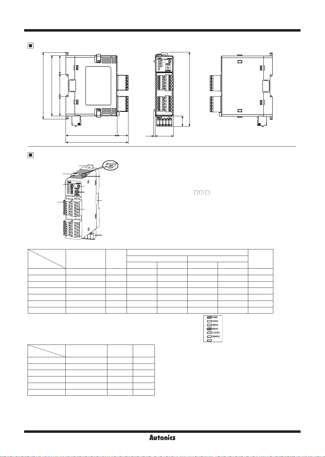
Dimensions
110
100
36.6 31.232.2
7
10
3
1
Control
output
※
4
※
5
-
18.6
2.9
30
1. Sensor input connector
2. Control output connector
3. Power/Comm. terminal
[only for basic module (TM - 2 B)]
Suppling power to basic/expansion modules and communicating with over
1 module(s).
4. PC loader port
It is the PC loader port for serial communication between one module
and PC to set parameter and monitoring by DAQMaster. Use this for
connecting SCM-US (USB to serial converter, sold separately).
※
When using PC loader port (connecting SCM-US), communication via
power/comm. terminal is blocked and monitoring is not available.
Alarm output
N.O. (Normally Open) N.C. (Normally Closed)
OFF (OPEN) ON (CLOSE) OFF (CLOSE) ON (OPEN)
- - - -
- - - -
- - - -
OFF ON OFF ON OFF
OFF ON OFF ON OFF
OFF ON OFF ON OFF
OFF ON OFF ON OFF
84.8
103.4
Unit Description
9
8
5
4
6
1
2
5. Indicators
●TM2 Series
Status
Indicator
PWR (green)
Initial power ON
※
3
ON ON
CH1 (red) Flash (2,400bps) ON
CH2 (red) Flash (4,800bps) ON
AL1 (yellow) Flash (9,600bps) ON
AL2 (yellow) Flash (19,200bps) ON
AL3 Flash (38,400bps)
AL4
※
1: When power is supplied initially, the set communication speed LED flashes for 5 sec.
- -
※
17.3
122.3
Autotuning
ON
Flash
Flash
(unit: mm)
※
2
●TM4 Series
Status
Indicator
PWR (green)
※
3
Initial power ON
ON ON ON
Control
※
1
output
CH1 (red) Flash (2,400bps) ON Flash
CH2 (red) Flash (4,800bps) ON Flash
CH3 (red) Flash (9,600bps) ON Flash
CH4 (red) Flash (19,200bps) ON Flash
Flash (38,400bps)
6. Communication address setting switch (SW1):
7. Communication address group switch (SW2):
8. Lock switch:
9. Rail Lock:
10. END cover
Used for fixing modules at top and bottom.
Used for installing at DIN rail or using bolts.
: Remove it when connecting each module to connect an expansion connector.
- -
Set the communication address.
When setting the communication address over 16, select +16.
J-54
Autotuning
※
※
2: The auto-tuning CH LED flashes for 1 sec in turn.
2
※
3: The PWR LED flashes during communication for 1 sec in turn.
※
4: Turns ON when CH1 control method is heating & cooling control
and cooling output occurs.
(disable AL1 setting)
※
5: Turns ON when CH2 control method is heating & cooling control
and cooling output occurs.
(disable AL2 setting)

2/4-CH Modular Type, PID Control
Connections and Block Diagram
TM2 Series
CURRENT
0.0A-50.0A
DIGITAL
INPUT
CH1 IN
CH2 IN
CH3 IN
CH4 IN
※
: Available for
single module
DI-1
DI-2
CH1 IN
TC
CH2 IN
TC
TM4 Series
Port A
A
B
B'
TC
RTD
A
B
B'
RTD
TC
A
B
B'
TC
RTD
A
B
B'
RTD
TC
CT1
CT2
RTD
RTD
1
2
3
4
5
6
7
8
9
10
11
12
A
B
B'
A
B
B'
ADC
ADC
ADC
ADC
ADC
1
2
ADC
3
4
5
6
7
ADC
8
9
10
11
ADC
12
CONTROL
CIRCUIT
RS485
CIRCUIT
1 2 3 4 5
A B
RS485
Serial
CONTROL
CIRCUIT
RS485
POWER
CIRCUIT
CIRCUIT
1 2 3 4 5
N.C
A B
RS485
N.C
POWER
CIRCUIT
SOURCE
24VDC
SOURCE
24VDC
OUTPUT
CIRCUIT
OUTPUT
CIRCUIT
OUTPUT
CIRCUIT
13
14
15
16
17
18
19
20
21
22
13
14
15
16
17
18
19
20
21
22
SSR OUT1
V
22VDC ±3V
30mA Max.
SSR OUT2
V
22VDC ±3V
30mA Max.
SSR OUT3
V
22VDC ±3V
30mA Max.
SSR OUT4
22VDC ±3V
V
30mA Max.
SCM-US (USB to Serial converter)
SSR OUT1
12VDC ±3V
30mA Max.
RELAY AL1 OUT
250VAC 3A 1a
RELAY AL2 OUT
250VAC 3A 1a
SSR OUT2
12VDC ±3V
30mA Max.
RELAY AL3
250VAC 3A 1a
RELAY AL4
250VAC 3A 1a
※
RELAY AL3/4 is available only for TM2-42 model.
RELAY OUT1
250VAC 3A 1a
30VDC 3A 1a
RELAY OUT2
250VAC 3A 1a
30VDC 3A 1a
RELAY OUT3
250VAC 3A 1a
30VDC 3A 1a
RELAY OUT4
250VAC 3A 1a
30VDC 3A 1a
SCM-38I
(RS232C to RS485 converter)
CURRENT OUT1
DC0/4-20mA
Load 500Ω Max.
CURRENT OUT2
DC0/4-20mA
Load 500Ω Max.
※
RELAY OUT1
250VAC 3A 1a
30VDC 3A 1a
RELAY OUT2
250VAC 3A 1a
30VDC 3A 1a
Use crimp terminals of size specied below.
a
c
<Crimp terminal>
Terminal number a b c
1 to 12 10
13 to 22 10
RS232C
b
(unit: mm)
Max. 1.7 Max. 3.7
Max. 2.1 Max. 4.2
SENSORS
CONTROLLERS
MOTION DEVICES
SOFTWARE
(J)
Temperature
Controllers
(K)
SSRs
(L)
Power
Controllers
(M)
Counters
(N)
Timers
(O)
Digital
Panel Meters
(P)
Indicators
(Q)
Converters
(R)
Digital
Display Units
(S)
Sensor
Controllers
(T)
Switching
Mode Power
Supplies
※
Port B
: Available for
single/multi module
1 2 3 4 5
RS485 A (+)
RS485 B (-)
N
- +
.
C
SOURCE
24VDC 5W
※
This connector is
available only for
standard model
(TM
SCM-US48I
(USB to RS485 converter)
SCM-WF48
(Wi-Fi/RS485, USB wireless
communication converter)
B).
PC
<RS485 communication support external device>
PLC
GP/LP
J-55
(U)
Recorders
(V)
HMIs
(W)
Panel PC
(X)
Field Network
Devices

TM Series
Installation
● Connector connection
Control output
Sensor input
connector
Power / Comm. connector
(only for basic module:
TM - 2 B
Bolt inserting
●
①
connector
● Multi module connection
④
③
②
③
TM - 2 E
(expansion module)
M4 Bolt
③
①
②
TM - 2 B
(basic module)
Remove each module’s END covers.
①
(do not remove at the ends of END covers)
Connect expansion connectors between modules.
②
Push each modules. (max. 30 units)
③
Push the lock switch to lock direction.
④
※
Supply adequate power for power input specications and overall capacity.
(Max. power when connecting 31 modules:
31 units×5W=155W)
M4 Bolt
TM - 2 E
(expansion module)
⑤
①
①
Pull each Rail Lock switch up and down.
DIN rail Installation
●
[Installation method]
①
Put the top edge of the rail Lock
on the top edge or the DIN rail.
②
Push the module body in while
pressing down.
※
Install the units vertically.
110
②
②
Insert the bolts to fix.
(Tightening torque is 0.5N·m to 0.9N·m.)
①
②
[Removal method]
①
Press down the module body.
②
Pull the module body forward.
①
②
※
Use end plates (sold separately, not available from Autonics) to
x rmly.
END PLATE
J-56

2/4-CH Modular Type, PID Control
Input Sensor Type and Temperature Range
Input sensor No. Dot Display Input range (℃) Input range (℉)
K(CA)
J(IC)
E(CR)
T(CC)
B(PR) 8 1 B(PR) 0 to 1800 32 to 3272
Thermocouple
R(PR) 9 1 R(PR) 0 to 1750 32 to 3182
S(PR) 10 1 S(PR) 0 to 1750 32 to 3182
N(NN) 11 1 N(NN) -200 to 1300 -328 to 2372
※
C(TT)
※
G(TT)
L(IC)
U(CC)
Platinel II 18 1 PLII 0 to 1400 32 to 2552
JPt 100Ω
RTD
DPt 100Ω
※
1: C(TT): Same as existing W5(TT).
※
2: G(TT): Same as existing W(TT).
※
Default: K(CA).H
Error Display
Status
Indicators
PWR (red) ON
CH (red)
※
1
Disconnected input sensors Out of temperature range
Flash (for 0.5 sec in turn)
Comm. output (decimal) Outputs '31000' Outputs '30000 (high-limit)', '-30000 (low-limit)'
DAQMaster Displays 'OPEN' Displays 'HHHH (high-limit)', 'LLLL (low-limit)'
※
1: The applied CH LED indicator flashes.
0 1 K(CA).H -200 to 1350 -328 to 2462
1 0.1 K(CA).L -200.0 to 1350.0 -328.0 to 2462.0
2 1 J(IC).H -200 to 800 -328 to 1472
3 0.1 J(IC).L -200.0 to 800.0 -328.0 to 1472.0
4 1 E(CR).H -200 to 800 -328.0 to 1472
5 0.1 E(CR).L -200.0 to 800.0 -328.0 to 1472.0
6 1 T(CC).H -200 to 400 -328 to 752
7 0.1 T(CC).L -200.0 to 400.0 -328.0 to 752.0
1
12 1 C(TT) 0 to 2300 32 to 4172
2
13 1 G(TT) 0 to 2300 32 to 4172
14 1 L(IC).H -200 to 900 -328 to 1652
15 0.1 L(IC).L -200.0 to 900.0 -328.0 to 1652.0
16 1 U(CC).H -200 to 400 -328 to 752
17 0.1 U(CC).L -200.0 to 400.0 -328.0 to 752.0
19 1 JPt100.H -200 to 600 -328 to 1112
20 0.1 JPt100.L -200.0 to 600.0 -328.0 to 1112.0
21 1 DPt100.H -200 to 600 -328 to 1112
22 0.1 DPt100.L -200.0 to 600.0 -328.0 to 1112.0
SENSORS
CONTROLLERS
MOTION DEVICES
SOFTWARE
(J)
Temperature
Controllers
(K)
SSRs
(L)
Power
Controllers
(M)
Counters
(N)
Timers
(O)
Digital
Panel Meters
(P)
Indicators
(Q)
Converters
(R)
Digital
Display Units
J-57
(S)
Sensor
Controllers
(T)
Switching
Mode Power
Supplies
(U)
Recorders
(V)
HMIs
(W)
Panel PC
(X)
Field Network
Devices

TM Series
Communication Setting
It is for parameter setting and monitoring via external devices (PC, PLC, etc.).
Interface
Comm. protocol Modbus RTU Comm. distance Max. 800m
Connection type RS485 Comm. speed 2400, 4800, 9600 (default), 19200, 38400 bps
Application standard Compliance with EIA RS485 Start bit 1-bit (xed)
Max. connection 31 units (address: 01 to 31) Data bit 8-bit (xed)
Synchronous method Asynchronous Parity bit None (default), Odd, Even
Comm. method Two-wire half duplex Stop bit 1-bit, 2-bit (default)
※
It is not allowed to set overlapping communication address at the same communication line.
Use twisted pair wire for RS485 communication.
Application of system organization
RS232C/
USB/Wi-Fi
Comm.
converter
Computer
※
It is recommended to use Autonics communication converter; SCM-WF48 (Wi-Fi to RS485·USB wireless communication
ON
RS485
B(-)
OFF
A(+)
Terminating resistance
(100 to 120Ω)
A(+) B(-) A(+) B(-) A(+) B(-)
RS485
DEVICE
#1
RS485
DEVICE
#2
RS485
DEVICE
#30
B(-)
A(+)
RS485
DEVICE
#31
converter, sold separately), SCM-US48I (USB to RS485 converter, sold separately), SCM-38I (RS232C to RS485
converter, sold separately).
Please use twisted pair wire, which is suitable for RS485 communication, for SCM-WF48, SCM-US48I and SCM-38I.
Communication Address Setting
Set the communication address by the communication address setting switch (SW1) and Communication address group switch (SW2).
When setting as 0, it does not operate communication.
(setting range: 01 to 31, factory default: [SW1] 1, [SW2] +0)
SW1
SW2
+0
+16
+0
+16
Caution for Communication Address Setting
When changing communication address via the Power/Comm. terminal, resupply the power.
0 1 2 3 4 5 6 7 8 9 A B C D E F
00 01 02 03 04 05 06 07 08 09 10 11 12 13 14 15
16 17 18 19 20 21 22 23 24 25 26 27 28 29 30 31
Sold Separately
Communication converter
SCM-WF48
(
Wi-Fi to RS485·USB wireless
communication converter)
J-58
SCM-US48I
(USB to RS485 converter)
SCM-38I
(RS232C to RS485 converter)
SCM-US
(USB to Serial converter)

Sold Separately
Current transformer (CT)
CSTC-E80LN
Ø23.3
Ø7
7
15026.5
10.5
CSTC-E200LN
Ø37.1
Ø13
10
13.5
CSTS-E80PP
21.4
15.4
0.5
Ø6
725.4
K (black)
L (white)
K (black)
L (white)
15040.8
2.9
2/4-CH Modular Type, PID Control
F=50Hz
100Ω
10Ω
Max. load current: 80A (50/60Hz)
※Max. load current for TM Series
is 50A.
Current ratio: 1/1000
Wire wounded resistance: 31Ω±10%
F=50Hz
100Ω
10Ω
Max. load current: 200A (50/60Hz)
※Max. load current for TM Series
is 50A.
Current ratio: 1/1000
Wire wounded resistance: 20Ω±10%
F=50Hz
100Ω
10Ω
3
(unit: mm)
3
(unit: mm)
4.5
10
Ta=25
℃
1
3.8
0.1
0.01
OUTPUT IN VOLTS RMS (V)
0.001
0.1
1 10 100 1000
SENSED CURRENT IN AMPS RMS (Io)
10
Ta=25
℃
1
0.1
0.01
OUTPUT IN VOLTS RMS (V)
0.001
0.1 1 10 100 1000
SENSED CURRENT IN AMPS RMS (Io)
10
Ta=25
℃
1
SENSORS
CONTROLLERS
MOTION DEVICES
SOFTWARE
(J)
Temperature
Controllers
(K)
SSRs
(L)
Power
Controllers
(M)
Counters
(N)
Timers
(O)
Digital
Panel Meters
(P)
Indicators
(Q)
Converters
10.5
40.2
31
Ø3.4
※
Do not supply primary current in case that CT output is open. High voltage will be generated in CT output.
※
The current for above CTs is 50A same but inner hole sizes are different. Please use this for your environment.
2.7
0.01
OUTPUT IN VOLTS RMS (V)
0.001
10
(unit: mm)
0.1 1 10 100 1000
SENSED CURRENT IN AMPS RMS (Io)
Max. load current: 80A (50/60Hz)
※
Max. load current for TM Series
is 50A.
Current ratio: 1/1000
Wire wounded resistance 31Ω±10%
Display units (DS/DA-T Series)
DS/DA-T Series
(RS485 communication input type display unit)
0.1
DS16- T
※
Connect RS485 communication input type display unit (DS/DA-T Series) and TM Series, the display unit displays present value of the
device without PC/PLC.
DS22/DA22- T
DS40/DA40- T DS60/DA60- T
J-59
(R)
Digital
Display Units
(S)
Sensor
Controllers
(T)
Switching
Mode Power
Supplies
(U)
Recorders
(V)
HMIs
(W)
Panel PC
(X)
Field Network
Devices

TM Series
Proper Usage
Simple failure diagnosis
● LED indicators flash (for 0.5 sec in turn), or external
device displays OPEN.
● Check input sensor setting.
● Disconnect the power and check the input connection.
● If input is connected, disconnect the input wiring
from the temperature controller and short the + and -
terminals. Power the temperature controller and check
if the external device displays the room temperature. If
it does not display the room temperature and continues
to display HHHH or LLLL, the controller is broken.
Please contact our technical support. (input type is
thermocouple)
● Output does not operate normally.
● Check that CH indicators for control output operates
normally.
● If CH indicators for control output does not operates,
check the parameter settings.
● If CH indicators for control output operates, remove
the control output connector and check the output.
● External device receives no-response or abnormal
data.
● Check the communication converter (SCM-WF48 or
SCM-US48I, SCM-38I, SCM-US, sold separately).
● Do not install communication converter line and AC
power supply lines.
● Use different communication converter power and
temperature controller power.
● Indicates damage to internal chip by strong noise.
Please contact our technical support. Locate the
source of the noise device countermeasures.
● Communication does not work between TM and
external device
● Check the communication converter power and
connections.
● Check the communication settings.
● Check the temperature controller and external device
connections.
Cautions during use
● Follow instructions in 'Cautions during Use'. Otherwise, It
may cause unexpected accidents.
● Check the polarity of the terminals before wiring the
temperature sensor.
For RTD temperature sensor, wire it as 3-wire type, using
cables in same thickness and length.
For thermocouple (CT) temperature sensor, use the
designated compensation wire for extending wire.
● Keep away from high voltage lines or power lines to
prevent inductive noise.
In case installing power line and input signal line closely,
use line filter or varistor at power line and shielded wire
at input signal line.
Do not use near the equipment which generates strong
magnetic force or high frequency noise.
● Do not apply excessive power when connecting or
disconnecting the connectors of the product.
● Install a power switch or circuit breaker in the easily
accessible place for supplying or disconnecting the
power.
● Do not use the unit for other purpose (e.g. voltmeter,
ammeter), but temperature controller.
● When changing the input sensor, turn off the power first
before changing.
After changing the input sensor, modify the value of the
corresponding parameter.
● 24VDC power supply should be insulated and limited
voltage/current or Class 2, SELV power supply device.
● Do not overlapping communication line and power line.
Use twisted pair wire for communication line and connect
ferrite bead at each end of line to reduce the effect of
external noise.
● Make a required space around the unit for radiation of
heat.
For accurate temperature measurement, warm up the
unit over 20 min after turning on the power.
● Make sure that power supply voltage reaches to the
rated voltage within 2 sec after supplying power.
● Do not wire to terminals which are not used.
● Install DIN rail vertically from the ground.
● This unit may be used in the following environments.
Indoors (in the environment condition rated in
①
'Specifications')
Altitude max. 2,000m
②
Pollution degree 2
③
Installation category II
④
J-60
 Loading...