

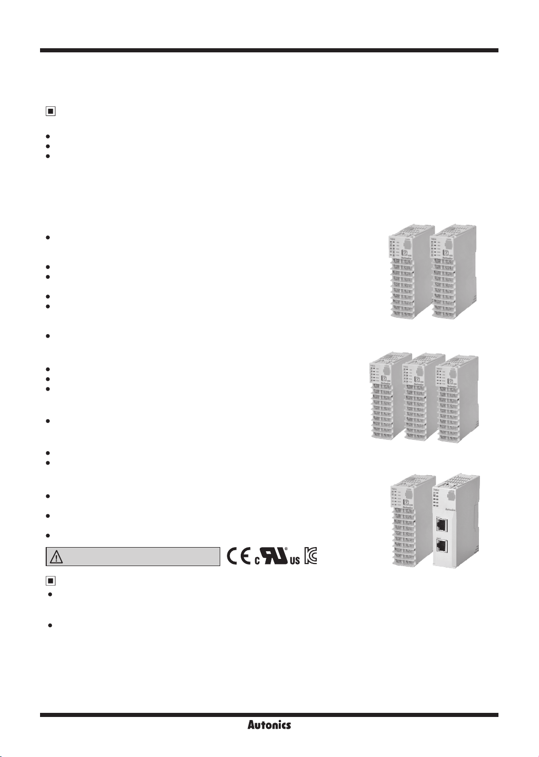
TMH Series
-|Transparent setting guide|-
Multi-Channel Modular Type High Performance
Temperature Controller
Feature
[Common]
Easy maintenance with separated body/base parts
No communication and power supply for expansion modules required using module connectors: Up to 32 modules
PC parameter setting via PC (USB cable and RS485 communication):
Supports comprehensive device management program (DAQMaster)
Communication converter, sold separately: SCM-US (USB/Serial converter),
※
SCM-38I (RS232C/RS485 converter), SCM-US48I (USB/RS485 converter),
SCM-WF48 (Wi-Fi/RS485.USB wireless communication converter),
EXT-US (converter cable)
[TMH2/4 Series (control module)]
One module supports multi channels (2 channels/4 channels) for
input/output control : connecting TMH2/4, up to 32 modules
(2 channels: 64 channels/4 channels: 128 channels)
High-speed sampling with 50ms and ±0.3% measuring accuracy
Simultaneous heating/cooling control and auto/manual control
for high-performance control
Selectable current output or SSR drive output
Each channel insulated (dielectric strength 1,000VAC)
CT input terminal for measuring load current
※
(※CT, sold separately: CSTC-E80LN, CSTC-E200LN, CSTS-E80PP)
Multi input/Multi range
[TMHA (analog input/output option module)]
4 channels, multi input/multi range/transmission output (DC0-20mA or 4-20mA)
Each channel insulated (dielectric strength 1,000VAC)
High-speed sampling with 50ms and ±0.3% measuring accuracy
[TMHE (digital input/alarm output option module)]
Digital input (8 types)/Alarm output (8 types)
[TMHCT (CT input option module)]
8 CT inputs
CT input status indicators
[TMHC (communication module)]
Connection expansion to master devices (PC, PLC, etc) with
TMH2/4 (control module) and TMHA/E/CT (option module) (up to 16 modules)
One module connects up to 32 control/option modules
(16 control modules and 16 option modules)
PLC ladderless (RS422/RS485), Ethernet communication supported
Please read “Safety Considerations”
in the instruction manual before using.
Manuals
For the detail information and instructions, please refer to the user manual and the user manual for communication, and
be sure to follow cautions written in the technical descriptions (catalog, website).
Visit our website (www.autonics.com) to download manuals.
User manual describes for specications and function, and communication manual describes for RS485 communincation
(protocol Modbus RTU) and parameter address map data.
J-32
Multi-Channel Modular Type High Performance
-|Transparent setting guide|-
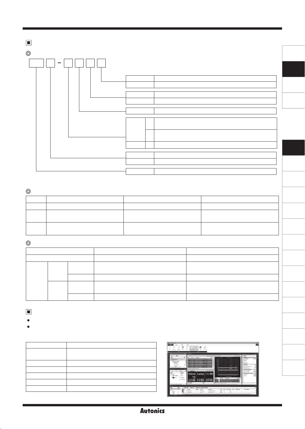
Ordering Information
Control module
2 4 2 R BTMH
Module
type
Control output
Power supply
Input/Output option
Channels
Item
1: Since the expansion module is not supplied with power/comm. terminal. Order it with the basic module.
※
B
E
R
C
2
2CH
4CH N
2
4
TMH
Basic module
Expansion module
1
※
Relay output
Selectable current or SSR drive output
24VDC
CT input, digital input (DI-1/2),
2
alarm output 1/2, RS485 comm. output
CT input, digital input (DI-1/2),
4
alarm output 1/2/3/4, RS485 comm. output
CT input, RS485 comm. output
2 channels
4 channels
Advanced Multi-Channel Modular Temperature Controller
SENSORS
CONTROLLERS
MOTION DEVICES
SOFTWARE
(J)
Temperature
Controllers
(K)
SSRs
(L)
Power
Controllers
Option module
Type Analog input/output Digital input, alarm output CT input
Model TMHA-42AE TMHE-82RE TMHCT-82NE
Input
Output
Temperature sensor/
Analog input 1 to 4
Transmission output
(0/4-20mA) 1 to 4
Digital input 1 to 8 CT input 1 to 8
Alarm output 1 to 8
-
Communication module
Type PLC ladderless communication Ethernet communication
Model TMHC-22LE TMH-22EE
COM1
(Master,
Communication
PLC)
COM2
(Master,
Group)
Comprehensive Device Management Program
DAQMaster is comprehensive device management program. It is available for parameter setting, monitoring.
Visit our website (www.autonics.com) to download user manual and comprehensive device management program.
< Computer specication for using software >
Item Minimum requirements
System
Operating system Microsoft Windows 98/NT/XP/Vista/7/8/10
Memory 256MB or more
Hard disk More than 1GB of free hard disk space
VGA 1024×768 or higher resolution display
Others RS-232 serial port (9-pin), USB port
Connection
method
RS422, RS485 Ethernet
Protocol Modbus RTU, PLC ladderless comm. Modbus TCP
Connection
method
RS422, RS485 Ethernet
Protocol Modbus RTU Modbus TCP
(DAQMaster)
< DAQMaster screen >
IBM PC compatible computer with Intel
Pentium Ⅲ or above
(M)
Counters
(N)
Timers
(O)
Digital
Panel Meters
(P)
Indicators
(Q)
Converters
(R)
Digital
Display Units
(S)
Sensor
Controllers
(T)
Switching
Mode Power
Supplies
(U)
Recorders
(V)
HMIs
(W)
Panel PC
(X)
Field Network
Devices
J-33
TMH Series
-|Transparent setting guide|-
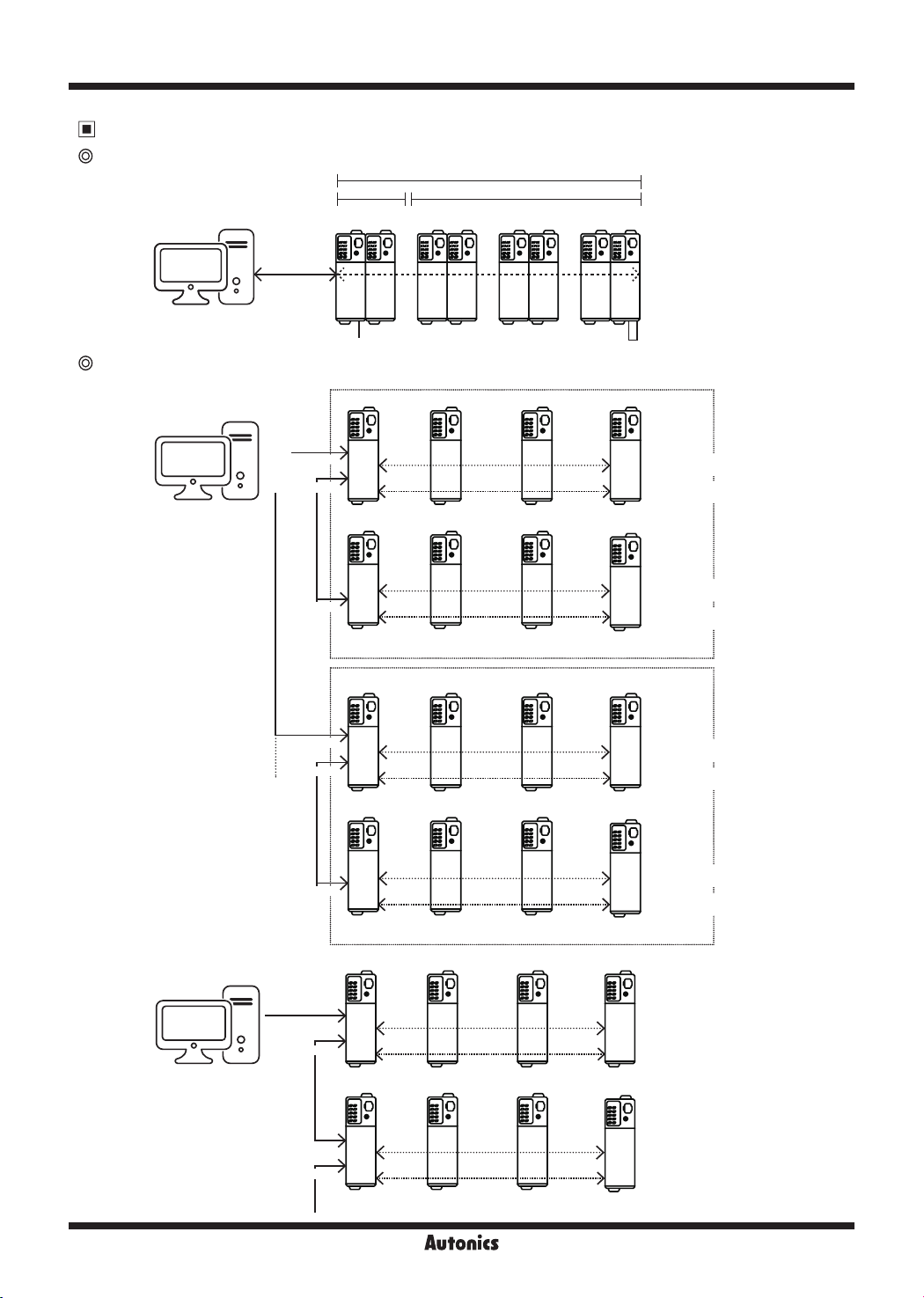
Max. 32 units
Terminal resistance
Internal
Connection Examples
TMH2/4, TMHA, TMHE, TMHCT inter-working configuration example
Address
range:
External
comm.
Master
(PC, PLC, HMI)
TMHC configuration example
● PLC ladderless communication
Master
Master
(PC, PLC, HMI)
(PC, PLC, HMI)
1. When using TMHC,
※
in case connecting
only TMHC to Master
(PC, PLC, etc.),
communication
address of TMHC
and TMH2/4 Series
control module can be
duplicated. However,
in case connecting
both TMHC and
TMH2/4 Series control
module to Master,
communication
address must not be
duplicated.
(If the TMHC and TMH
modules communicate
Max. connection:
4 group
with Master at
the same time, a
communication error
may occur.)
● Ethernet communication
Group1
Port 1
Port 2
Group2
Max. 16 units
TMH2/4
1 to 32
24VDC
TMHC TMH2/4
COM1
COM2
TMHC TMH2/4
COM2
Max. connection: 4 TMHC per a group
TMHC
COM1
COM2
TMHC
COM2
Max. connection: 4 TMHC per a group
TMHC TMH2/4
TMH2/4
TMH2/4
TMHA
33 to 48
Max. 16 units
※1
※1
※1
※1
※1
TMHE
49 to 64
TMHA/E/CT
TMHA/E/CT
TMHA/E/CT
TMHA/E/CT
TMHA/E/CT
TMHCT
65 to 80
※
※
comm.
Internal comm. of
control module
Internal comm. of
comm. module
Internal comm. of
control module
Internal comm. of
comm. module
Internal comm. of
control module
Internal comm. of
comm. module
Internal comm. of
control module
Internal comm. of
comm. module
※
Internal communication:
Receiving/Sending data
between TMH2/4 and
TMHA/E/CT
External communication:
Communication with
Master for controlling
Each module is
available to monitoring
at DAQMatser via PC
loader
COM1
COM2
Master
Master
(PC, PLC, HMI)
(PC, PLC, HMI)
Max. connection:
16 TMHC
COM2
J-34
TMHC TMH2/4
Internal comm. of
control module
Internal comm. of
comm. module
※1
TMHA/E/CT
Internal comm. of
control module
Internal comm. of
comm. module
Multi-Channel Modular Type High Performance
-|Transparent setting guide|-
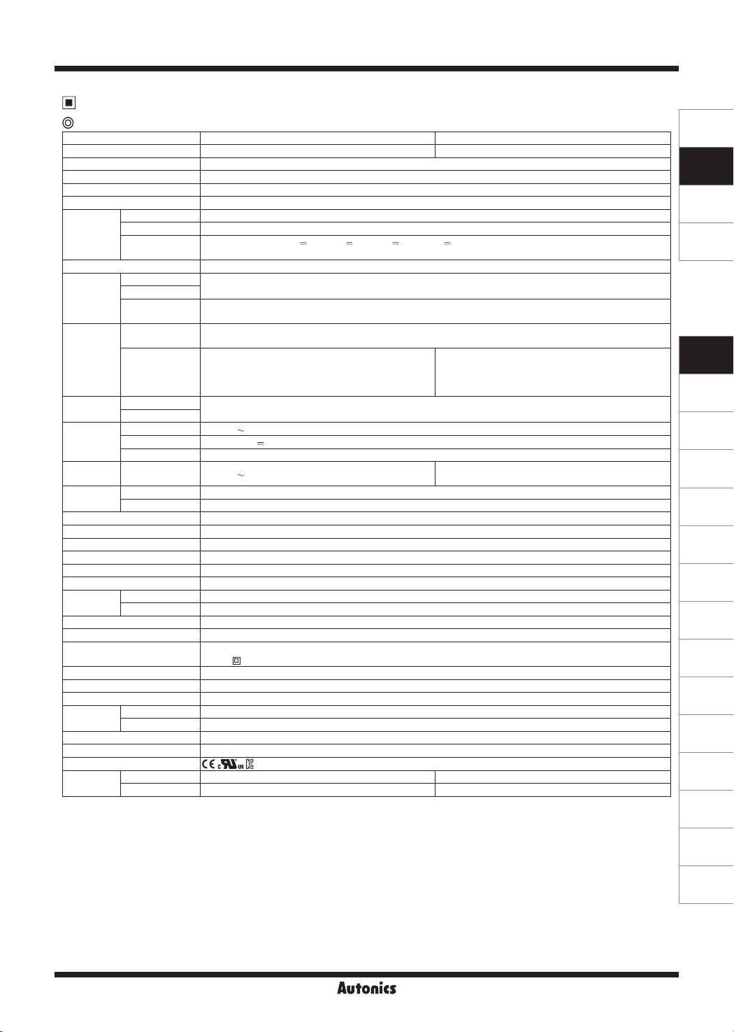
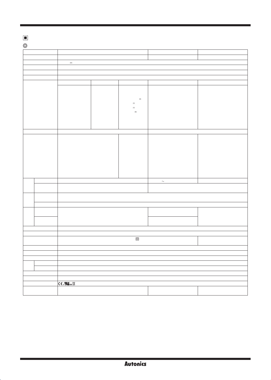
Specifications
Control module
Series TMH2 TMH4
No. of channels 2 channels 4 channels
Power supply 24VDC
Permissible voltage range 90 to 110% of rated voltage
Power consumption Max. 5W (for max. load)
Display method None- parameter setting and monitoring is available at external devices (PC, PLC, etc.)
Thermocouple K(CA), J(IC), E(CR), T(CC), B(PR), R(PR), S(PR), N(NN), C(TT), G(TT), L(IC), U(CC), Platinel II
Input type
RTD
Analog
Sampling cycle 50ms (2 channel or 4 channel synchronous sampling)
Thermocouple
Measured
accuracy
RTD
Analog
※
1
CT input
Option input
Digital input
Control
method
Control
output
Option
output
Communication
Heating, Cooling
Heating&Cooling
Relay 250VAC
SSR Max. 12VDC
※
3
Current
Alarm 250VAC
Comm. terminal RS485 (Modbus RTU protocol)
PC loader TTL (Modbus RTU protocol)
Hysteresis RTD/Thermocouples: 1 to 100℃/℉ (0.1 to 100.0℃/℉), analog: 1 to 100 digit
Proportional band (P) RTD/Thermocouples: 1 to 999℃/℉ (0.1 to 999.9℃/℉), analog: 0.1 to 999.9 digit
Integral time (I) 0 to 9999 sec
Derivative time (D) 0 to 9999 sec
Control period (T) Relay output: 0.1 to 120.0 sec, SSR output: 1.0 to 120.0 sec
Manual reset 0 to 100% (0.0 to 100.0% )
Relay
life cycle
Mechanical Min. 10,000,000 operations
Electrical Min. 100,000 operations (250VAC 3A resistance load)
Memory retention Approx. 10 years (non-volatile semiconductor memory type)
Insulation resistance 100MΩ (at 500VDC megger)
Insulation type
Dielectric strength 1,000VAC 50/60Hz for 1 min (between input terminals and power terminals)
Vibration 0.75mm amplitude at frequency of 5 to 55Hz (for 1 min) in each X, Y, Z direction for 2 hours
Noise immunity ±0.5kV the square wave noise (pulse width: 1㎲) by the noise simulator
Environment
Ambient temp. -10 to 50℃, storage: -20 to 60
Ambient humi. 35 to 85%RH, storage: 35 to 85%RH
Protection structure IP20 (IEC standard)
Accessories Expansion connector: 1, module lock connector: 2
Approval
Weight
※
1: Connecting 1 or more expansion module can vary measurement accuracy about ±1℃, regardless of the number of connected
※
2: At room temperature (23℃±5℃)
Expansion module
expansion module.
Basic module Approx. 250.8g (approx. 177.7g) Approx. 250.4g (approx. 177.3g)
※
4
• Thermocouple K, J, N, E below -100℃, L, U, PLII and RTD Cu50Ω, DPt50Ω: (PV ±0.3% or ±2℃, higher one) ±1-digit
• Thermocouple C, G and R, S below 200℃: (PV ±0.3% or ±3℃, higher one) ±1-digit
• Thermocouple B below 400℃: there is no accuracy standards.
Out of room temperature range
• RTD Cu50Ω, DPt50Ω: (PV ±0.5% or ±3℃, higher one) ±1-digit
• Thermocouple R, S, B, C, G: (PV ±0.5% or ±5℃, higher one) ±1-digit
• Others blow -100℃: within ±5
※
3: If the control output is set to current output, the heater current value monitoring function through the CT input terminal of the control
module is not available.
※
4: The weight includes packaging. The weight in parenthesis is for unit only.
※
Environment resistance is rated at no freezing or condensation.
ᜡ
DPt100Ω, JPt100Ω, DPt50Ω, Cu100Ω, Cu50Ω, Nikel 120Ω 3-wire type (permissible line resistance max. 5Ω)
• Voltage: 0-100mVDC , 0-5VDC , 1-5VDC , 0-10VDC
• Current: 0-20mA, 4-20mA
※
• At room temperature (23℃±5℃): (PV ±0.3% or ±1℃, higher one) ±1-digit
2
• Out of room temperature range: (PV ±0.5% or ±2℃, higher one) ±1-digit
• At room temperature (23℃±5℃): ±0.3% F.S. ±1-digit
• Out of room temperature range: ±0.5% F.S. ±1-digit
0.0-50.0A (primary current measurement range) ※CT ratio=1/1000
Measured accuracy: ±5% F.S. ±1-digit
• Connect input: ON - max. 1kΩ, OFF - min. 100kΩ
• Solid-state input: ON - max. residual voltage 0.9V,
OFF - max. leakage current 0.5mA
-
• Outow current : approx. 0.3mA per input
ON/OFF control, P, PI, PD, PID control
3A 1a
±3V 20mA
Selectable DC 4-20mA or DC 0-20mA (load resistance max. 500Ω)
3A 1a
-
Double insulation or reinforced insulation
, dielectric strength between the measuring input part and the power part: 1kV)
(mark:
℃
Approx. 245.7(approx. 172.6g) Approx. 245.1g(approx. 172.2g)
℃
SENSORS
CONTROLLERS
MOTION DEVICES
SOFTWARE
(J)
Temperature
Controllers
(K)
SSRs
(L)
Power
Controllers
(M)
Counters
(N)
Timers
(O)
Digital
Panel Meters
(P)
Indicators
(Q)
Converters
(R)
Digital
Display Units
(S)
Sensor
Controllers
(T)
Switching
Mode Power
Supplies
(U)
Recorders
(V)
HMIs
(W)
Panel PC
(X)
Field Network
Devices
J-35
TMH Series
-|Transparent setting guide|-
Specifications
Option module
Model TMHA-42AE TMHE-82RE TMHCT-82NE
No. of channels 4 channels 8 points 8 points
Power supply
Permissible voltage range
Power consumption Max. 5W (for max. load)
Display method None- parameter setting and monitoring is available at external devices (PC, PLC, etc.)
Input type
Sampling cycle 50ms (4CH synchronous sampling)
Measured
accuracy
Output
Comm.
Relay
life
cycle
Memory retention Approx. 10 years (non-volatile semiconductor memory type)
Insulation resistance Over 100MΩ (500VDC megger)
Insulation type
Dielectric strength 1,000VAC 50/60Hz for 1 min (between power source terminal and input terminal)
Vibration 0.75mm amplitude at frequency of 5 to 55Hz (for 1 min) in each X, Y, Z direction for 2 hours
Noise immunity Square shaped noise by noise simulator (pulse width 1㎲) ±0.5kV R-phase, S-phase
Environment
Protection structure IP20 (IEC standard)
Accessories Expansion connector: 1, module lock connector: 2
Approval
Weight
※
1: Voltage of power supply/communication terminal placed in the backside of TMH2/4 Series (basic control module)
※
2: In case of TMHA, connecting 1 or more expansion module can vary measurement accuracy about ±1℃, regardless of the number of
※
3: At room temperature (23℃±5℃)
Out of room temperature range
• RTD Cu50Ω, DPt50Ω: (PV ±0.5% or ±3℃, higher one) ±1-digit
• Thermocouple R, S, B, C, G: (PV ±0.5% or ±5℃, higher one) ±1-digit
• Others blow -100℃: within ±5
※
4: The weight includes packaging. The weight in parenthesis is for unit only.
※
Environment resistance is rated at no freezing or condensation.
※
1
24VDC
90 to 110% of rated voltage
Thermocouple RTD Analog Digital CT
DPt100Ω,
K(CA), J(IC), E(CR),
T(CC), B(PR), R(PR),
S(PR), N(NN), C(TT),
G(TT), L(IC), U(CC),
Platinel II
• At room temperature (23℃±5℃):
(PV ±0.3% or ±1℃, higher one)
※
3
※
2
Alarm
Transmission
Comm.
terminal
PC loader TTL (Modbus RTU protocol)
Mechanical
Electrical
Ambient temp.
Ambient humi.
※
4
connected expansion module.
• Thermocouple K, J, N, E below -100℃, L, U, PLII and RTD Cu50Ω, DPt50Ω:
(PV ±0.3% or ±2℃, higher one) ±1-digit
• Thermocouple C, G and S below 200℃: (PV ±0.3% or ±3℃, higher one) ±1-digit
• Thermocouple B below 400℃: there is no accuracy standards.
±1-digit
• Out of room temperature range:
(PV ±0.5% or ±2℃, higher one)
±1-digit
-
DC 4-20mA or DC 0-20mA
(load resistance max. 500Ω)
RS485 (Modbus RTU protocol)
-
Double insulation or reinforced insulation (mark:
measuring input part and the power part : 1kV)
-10 to 50℃, storage: -20 to 60
35 to 85%RH, storage: 35 to 85%RH
Approx. 233.8g (approx. 160.7g)
JPt100Ω,
DPt50Ω, Cu100Ω,
Cu50Ω, Nikel
120Ω 3-wire type
(permissible line
resistance max.
5Ω per line)
℃
• Voltage:
0-100mVDC ,
0-5VDC ,
1-5VDC ,
0-10VDC
• Current: 0-20mA,
4-20mA
• At room
temperature
(23℃±5℃):
±0.3% F.S.
±1-digit
• Out of room
temperature
range:
±0.5% F.S.
±1-digit
℃
• Connect input:
ON - max. 1kΩ,
OFF - min. 100kΩ
• Solid-state input:
ON - max. residual voltage 0.9V,
OFF - max. leakage current
0.5mA
• Outow current :
approx. 0.3mA per input
-
-
250VAC 3A 1a
-
Min. 10,000,000 operations
Min. 100,000 operations
(250VAC 3A resistance load)
, dielectric strength between the
Approx. 239g
(approx. 165.9g)
0.0-50.0A
(primary current measurement
range)
※
CT ratio=1/1000
±5% F.S. ±1-digit
-
-
-
Approx. 220.6g
(approx. 147.5g)
J-36
Multi-Channel Modular Type High Performance
-|Transparent setting guide|-
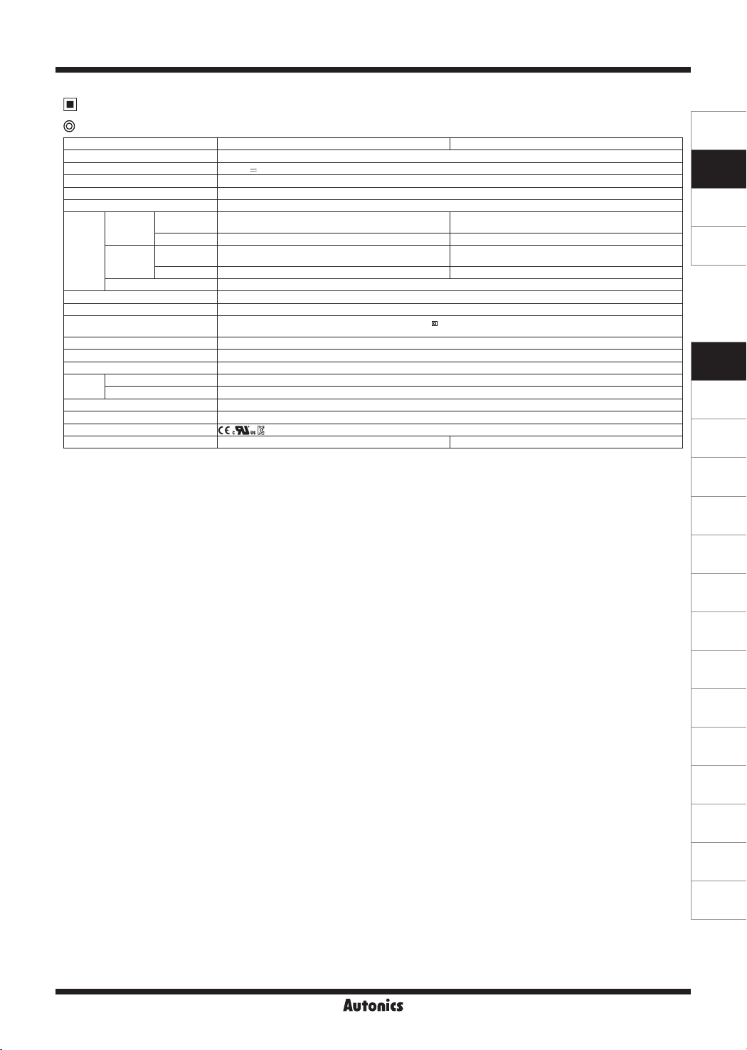
Specifications
Communication module
Model TMHC-22LE TMHC-22EE
Communication port COM1/2
Power supply
Permissible voltage range 90 to 110% of rated voltage
Power consumption Max. 5W (for max. load)
Display method
Comm.
Memory retention Approx. 10 years (non-volatile semiconductor memory type)
Insulation resistance Over 100MΩ (500VDC megger)
Insulation type
Dielectric strength 1,000VAC 50/60Hz for 1 min (between power source terminal and input terminal)
Vibration
Noise immunity
Environ
-ment
Protection structure IP20(IEC standard)
Accessories Expansion connector: 1, module lock connector: 2
Approval
Weight
1:
※
2: The weight includes packaging. The weight in parenthesis is for unit only.
※
Environment resistance is rated at no freezing or condensation.
※
※1
24VDC
None- parameter setting and monitoring is available at external devices (PC, PLC, etc.)
COM1
(Master,
PLC)
COM2
(Master,
Group)
Connection
method
RS485/RS422 Ethernet
Protocol Modbus RTU, PLC ladderless comm. Modbus TCP
Connection
method
RS485/RS422 Ethernet
Protocol Modbus RTU Modbus TCP
PC loader TTL (Modbus RTU protocol)
Double insulation or reinforced insulation (mark: , dielectric strength between the measuring input part
and the power part : 1kV)
0.75mm amplitude at frequency of 5 to 55Hz (for 1 min) in each X, Y, Z direction for 2 hours
Square shaped noise by noise simulator (pulse width 1㎲) ±0.5kV R-phase, S-phase
Ambient temp. -10 to 50℃, storage: -20 to 60℃
Ambient humi. 35 to 85%RH, storage: 35 to 85%RH
※2
approx. 219g (approx. 147g) approx. 200g (approx. 129g)
Voltage of power supply/communication terminal placed in the backside of TMH2/4 Series (basic control module)
SENSORS
CONTROLLERS
MOTION DEVICES
SOFTWARE
(J)
Temperature
Controllers
(K)
SSRs
(L)
Power
Controllers
(M)
Counters
(N)
Timers
(O)
Digital
Panel Meters
(P)
Indicators
(Q)
Converters
(R)
Digital
Display Units
(S)
Sensor
Controllers
(T)
Switching
Mode Power
Supplies
(U)
Recorders
(V)
HMIs
(W)
Panel PC
(X)
Field Network
Devices
J-37

TMH Series
-|Transparent setting guide|-
CT1
Error Display
Status
Indicator
PRW ON (red) ON (green)
※
3
CH
※
1: Input error: input value is below the input range (LLLL) / input value exceeds input range (HHHH) / input sensor wire is
Input error
Flash (red) Flash (red)
down or input sensor is disconnected (OPEN).
※
2: Remote SV error: communication error of Remote SV master and internal communication / input of master channel is
LLLL/HHHH/OPEN when the channel is subjected to display PV.
※
3: An indicator of relative channel flashes.
After main cause of the error is solved, error status is cleared and the device is returned to the normal operation
automatically
Dimensions
● Rail Lock position:
mounting with bolts
30 30
12
2-Ø4.1
※
1
Remote SV error
● Rail Lock position:
mounting on DIN Rail
※
2
(unit: mm)
100
109
119
100
110
85
Unit Description
Control module
8
3
7
9
10
1. Input/Output terminal
4
1
[Front/Side/Top]
5
6
11
2
9
10
For specific information about terminal formation,
please refer to '▣ Connections and Isolated Block Diagram'.
2. Power/Comm. terminal [basic module only]
Supplies power to both basic control/expansion module and communicates with one or more module.
3. CT input terminal
When using the CT input terminal, remove the rubber cap and connect CT in the same
direction with right image.
Connect CT with CICT4-
When connecting CT connector and CT input terminal,
※
(CT connector cable, sold separately).
align the concave part (凹) and the convex part (凸).
8
2
[Bottom]
Back
35mm
DIN RAIL
CT4
CT3
CT2
J-38
Front

Multi-Channel Modular Type High Performance
-|Transparent setting guide|-
Control module
4. Indicator
4
1
[Front/Side/Top]
3
8
7
9
5
6
10
11
2
10
9
8
2
[Bottom]
●TMH2 Series
Status
Indicator
LED 1 LED 2
PWR (green)
※
3
Initial
power ON
※
1
CH1 (red) ON Flash
LED 1
CH2 (red) ON Flash
(red) ON
(red) ON
Control
output
ON ON
※
4
※
5
(yellow) Flash (4,800bps) Module comm. status
AL1 (yellow) Flash (9,600bps)
AL2 (yellow) Flash (19,200bps)
LED 2
AL3 (yellow) Flash (38,400bps)
AL4 (yellow) Flash (115,200bps)
- -
- -
- -
- -
●TMH4 Series
Indicator
LED 1 LED 2
Status
Initial power ON
※
PWR (green)
3
CH1 (red) ON Flash
LED 1
CH2 (red) ON Flash
-
※
1
Control
output
ON ON
CH3 (red) ON Flash
CH4 (red) ON Flash
(yellow) Flash (4,800bps) Module comm. status
(yellow) Flash (9,600bps)
(yellow) Flash (19,200bps)
LED 2
(yellow) Flash (38,400bps)
(yellow) Flash (115,200bps)
※
1: At the moment when power is on, the indicator of set communication speed flashes for 5 sec.
※
2: Indicator of the channel, which is in the process of auto-tuning, flashes at 1 sec interval.
※
3: When communicating with external device, PWR indicator flashes.
※
4: Turns on, when CH1 outputs cooling control in the heating&cooling control method.
※
5: Turns on, when CH2 outputs cooling control in the heating&cooling control method.
※
6: Displays communication status in control output, auto-tuning or operating RUN mode.
- -
- -
- -
- -
Alarm output
Auto
N.O.(Normally Open) N.C. (Normally Closed)
※
2
tuning
OFF (OPEN) ON (CLOSE)
OFF (CLOSE)
OFF
OFF
※
6
OFF ON OFF ON
OFF ON OFF ON
OFF ON OFF ON
OFF ON OFF ON
※
Auto tuning
2
※
6
ON (OPEN)
ON: normal / flash: abnormal / OFF: not communicating
5. PC loader port: PC loader port supports serial communication between single module and PC.
It needs EXT-US (converter cable)+SCM-US (USB/Serial converter, sold separately) for communicating.
6. Communication address setting switch (SW1): Set the communication address.
If changing the communication address by setting switch, use the flat head driver which is 2mm size or plastic driver. If
not, it may cause product damage.
7. Communication address group switch (SW2): When setting the communication address over 16, select +16.
8. Rail lock: Rail lock helps installing the device to DIN rail or with bolts.
9. Lock lever: Lock lever holds module body and base tightly.
10. Module lock connecter hole: When connect modules, insert module lock connector in the hole in order to enhance
coherence between modules.
11. END cover: When connect modules, remove END cover in order to connect expansion connector.
SENSORS
CONTROLLERS
MOTION DEVICES
SOFTWARE
(J)
Temperature
Controllers
(K)
SSRs
(L)
Power
Controllers
(M)
Counters
(N)
Timers
(O)
Digital
Panel Meters
(P)
Indicators
(Q)
Converters
(R)
Digital
Display Units
(S)
Sensor
Controllers
(T)
Switching
Mode Power
Supplies
(U)
Recorders
(V)
HMIs
(W)
Panel PC
(X)
Field Network
Devices
J-39

TMH Series
-|Transparent setting guide|-
Option module
5
5
7
2
1
3
4
8
6
7
6
7
1. Input/Output terminal
[Front/Side/Top]
For specific information about terminal formation, please refer to '
Connections and Isolated Block Diagram'.
2. Indicator
●TMHA [analog input/output module]
Indicator
LED 1 LED 2
LED 1
Status
PWR (green)
CH1 (red)
CH2 (red)
CH3 (red)
CH4 (red)
Initial power ON
※
2
-
※
1
Internal comm. Transmission output
ON ON
-
-
-
(yellow) Flash (4,800bps) Module comm. status
(yellow) Flash (9,600bps) ON (CH1)
(yellow) Flash (19,200bps) ON (CH2)
LED 2
(yellow) Flash (38,400bps) ON (CH3)
(yellow) Flash (115,200bps) ON (CH4)
●TMHE [digital input, alarm output module]
Status
Initial power ON
※
1
Internal comm.
Indicator
※
2
ON ON
-
-
-
-
-
LED 1 LED 2
LED 1
PWR (green)
CH1 (red)
CH2 (red)
CH3 (red)
CH4 (red)
(yellow) Flash (4,800bps) Module comm. status
AL5 (yellow) Flash (9,600bps)
AL6 (yellow) Flash (19,200bps)
LED 2
AL7 (yellow) Flash (38,400bps)
AL8 (yellow) Flash (115,200bps)
-
-
-
-
●TMHCT [CT input module]
Indicator
LED 1 LED 2
LED 1
Status
Initial power ON
※
PWR (green)
2
(red) ON (40.1 to 50.0A)
(red) ON (30.1 to 40.0A)
-
※
1
CT input
※
4
ON ON
(red) ON (20.1 to 30.0A)
(red) ON (10.1 to 20.0A)
(yellow) Flash (4,800bps) Module comm. status
(yellow) Flash (9,600bps) ON (40.1 to 50.0A)
LED 2
(yellow) Flash (19,200bps) ON (30.1 to 40.0A)
(yellow) Flash (38,400bps) ON (20.1 to 30.0A)
(yellow) Flash (115,200bps) ON (10.1 to 20.0A)
3. PC loader port: PC loader port supports serial communication between single module and PC.
It needs EXT-US (converter cable)+SCM-US (USB/Serial converter, sold separately) for communicating.
4. Communication address setting switch (SW1): Set the communication address.
If changing the communication address by setting switch, use the flat head driver which is 2mm size or plastic driver. If not, it may cause
product damage.
5. Rail lock: Rail lock helps installing the device to DIN rail or with bolts.
6. Lock lever: Lock lever holds module body and base tightly.
7. Module lock connecter hole:
When connect modules, insert module lock connector in the hole in order to enhance coherence between modules.
8. END cover: When connect modules, remove END cover in order to connect expansion connector.
[Bottom]
ON
ON
ON
ON
※
3
-
-
-
-
Alarm output
N.O.(Normally Open) N.C. (Normally Closed)
OFF
(OPEN)
ON
(CLOSE)
OFF
(CLOSE)ON(OPEN)
OFF ON OFF ON
OFF ON OFF ON
OFF ON OFF ON
OFF ON OFF ON
※
3
OFF ON OFF ON
OFF ON OFF ON
OFF ON OFF ON
OFF ON OFF ON
※
1: At the moment when power is on, the indicator
Internal
comm.
-
-
-
-
※
3
-
-
-
-
of set communication speed flashes for 5 sec.
※
2: When communicating with external device,
PWR indicator flashes.
※
3
: Displays internal communication status between
modules.
ON: normal / flash: abnormal / OFF: not
communicating
※
4
: The indicator corresponding to the certain
setting value of CT input flashes according to
the parameter
[CT Input Value Indication Lamp
LED 1: CT Input Value Indication Lamp1 / LED 2:
CT Input Value Indication Lamp2
].
J-40

Multi-Channel Modular Type High Performance
-|Transparent setting guide|-
Communication module
5
6
6
SENSORS
8
2
1
3
4
9
7
8
7
8
1. Communication port
[Front/Side/Top]
Communication ports are varied by model specification.
Please refer to '
Connections and Isolated Block Diagram' for more detail information.
2. Indicator
●TMHC-22LE [RS422/RS485 ladderless communication module]
Status
Indicator
Initial power ON
PWR Flash (4,800bps) Flash (green)
LED 1 LED 2
LED1
(red)
(red)
(red)
(red)
Flash (9,600bps) Flash (TMH2/4)
Flash (19,200bps) Flash (TMHA)
Flash (38,400bps) Flash (TMHE)
Flash (115,200bps) Flash (TMHCT)
(yellow) Flash (4,800bps)
(yellow) Flash (9,600bps)
LED2
(yellow) Flash (19,200bps)
(yellow) Flash (38,400bps)
(yellow) Flash (115,200bps)
※
1: At the moment when power is on, the indicator of set communication speed flashes for 5 sec.
※1
Internal comm. Connection PLC ladderless comm.
-
- -
- -
- -
- -
-
-
-
-
-
ON Flash
ON (TMH2/4)
ON (TMHA)
ON (TMHE)
ON (TMHCT)
●TMHC-22EE [Ethernet communication module]
Status
Indicator
PWR(green)
LED1
(red)
(red)
LED 1 LED 2
(red)
(red)
(yellow)
(yellow)
LED2
(yellow)
(yellow)
(yellow)
Initial power ON Internal comm. Connection
ON Flash (external device)
-
-
-
-
-
Flash (TMH2/4)
Flash (TMHA)
Flash (TMHE)
Flash (TMHCT)
ON
-
Sequence-ashing
vertically for 5 sec
-
-
-
-
-
-
-
Flash (Ethernet
comm.)
ON (TMH2/4)
ON (TMHA)
ON (TMHE)
ON (TMHCT)
3. PC loader port: PC loader port supports serial communication between single module and PC. It needs EXT-US (converter cable)+SCMUS (USB/Serial converter, sold separately) for communicating.
4. Communication address setting switch (SW1): Set the communication address.
If changing the communication address by setting switch, use the flat head driver which is 2mm size or plastic driver. If not, it may cause
product damage.
5. Communication mode switch (SW2): Select communication mode between RS485 and RS422. (TMHC-22LE only)
6. Rail lock: Rail lock helps installing the device to DIN rail or with bolts.
7. Lock lever: Lock lever holds module body and base tightly.
8. Module lock connecter hole: When connect modules, insert module lock connector in the hole in order to enhance coherence between
modules.
9. END cover: When connect modules, remove END cover in order to connect expansion connector.
[Bottom]
Flash (red, Reading)
(Sending)
-
-
-
-
CONTROLLERS
MOTION DEVICES
SOFTWARE
(J)
Temperature
Controllers
(K)
SSRs
(L)
Power
Controllers
(M)
Counters
(N)
Timers
(O)
Digital
Panel Meters
(P)
Indicators
(Q)
Converters
(R)
Digital
Display Units
(S)
Sensor
Controllers
(T)
Switching
Mode Power
Supplies
(U)
Recorders
(V)
HMIs
(W)
Panel PC
J-41
(X)
Field Network
Devices

TMH Series
-|Transparent setting guide|-
CT1
CT4
Connections and Isolated Block Diagram
Use terminals of size specied below.
※
b
a
<Round>
a
b
<Forked>
a Min. 3.0mm Min. 3.0mm
b Max. 5.8mm Max. 5.8mm
Control module
●CT input terminal on the top ● Power/Comm. terminal on the back
※
When use the CT input terminals,
remove the robber cap.
※
Connect CT with CICT4-□(CT connector cable,
sold separately).
●TMH2 Series
CH1
RELAY OUT1: 250VAC 3A 1a
CURRENT OUT1:
DC0/4-20mA Load 500Ω
SSR OUT1:
12VDC ±3V 20mA Max.
CH2
RELAY OUT2: 250VAC 3A 1a
CURRENT OUT2:
DC0/4-20mA Load 500Ω
SSR OUT2:
12VDC ±3V 20mA Max.
+
㎃
-
+
㎃
-
+++
V
---
V
TC
㎃
+
-
TC
㎃
RTD
+++
---
RTD
A
B
B'
V
A
B
B'
+
V
-
Back
[basic module only]
24VDC
+
-
CT3
CT2
Front
1
2
3
4
5
6
7
8
9
10
11
12
13
14
15
16
17
18
19
20
DIGITAL
INPUT 1
RELAY AL1 OUT1
250VAC 3A 1a
RELAY AL2 OUT1
250VAC 3A 1a
DIGITAL
INPUT 2
RELAY AL3 OUT1
250VAC 3A 1a
RELAY AL4 OUT1
250VAC 3A 1a
●TMH4 Series
CH1
+++++
㎃
V
-----
RELAY OUT1:
250VAC 3A 1a
CURRENT OUT1:
DC0/4-20mA Load 500Ω
SSR OUT1:
12VDC ±3V 20mA Max.
CH2
㎃
V
RELAY OUT2:
250VAC 3A 1a
CURRENT OUT2:
DC0/4-20mA Load 500Ω
SSR OUT2:
12VDC ±3V 20mA Max.
A
1
B
2
B'
TC
㎃
+
-
TC
㎃
3
RTD
4
+
+
V
-
-
5
A
6
B
7
B'
8
RTD
9
+
+
V
-
-
10
RS485
(A+)
11
12
13
14
15
16
17
18
19
20
RS485
(B-)
-
+
B'
B
A
RTD
-
+
B'
B
A
RTD
V
V
S.G
RELAY OUT3:
250VAC 3A 1a
-
CURRENT OUT3:
㎃
DC0/4-20mA Load 500Ω
+
SSR OUT3:
12VDC ±3V 20mA Max.
----V
+++++
TC
RELAY OUT4:
250VAC 3A 1a
-
CURRENT OUT4:
㎃
DC0/4-20mA Load 500Ω
+
SSR OUT4:
12VDC ±3V 20mA Max.
-
V
+
TC
㎃
CH3
㎃
CH4
Option module
●TMHA [analog input/output module] ●TMHE [digital input, alarm output module]
CH1
+
㎃
V
-
CURRENT OUT1
DC0/4-20mA
Load 500Ω
+++
---
RTD
㎃
B
B'
+
-
A
A
CH2
+
㎃
V
-
CURRENT OUT2
DC0/4-20mA
Load 500Ω
B
+
B'
-
RTD
+
㎃
-
J-42
11
1
2
3
4
5
6
7
8
9
10
-
㎃
+
12
B'
13
B
A
RTD
B'
B
A
RTD
+++
TC
-
㎃
+
TC
14
15
16
17
18
19
20
CURRENT OUT3
DC0/4-20mA
Load 500Ω
---
-
㎃
V
+
CH3
CURRENT OUT4
DC0/4-20mA
Load 500Ω
-
-
㎃
V
+
+
CH4
DIGITAL
INPUT 1
DIGITAL
INPUT 2
DIGITAL
INPUT 3
DIGITAL
INPUT 4
DIGITAL
INPUT 5
DIGITAL
INPUT 6
DIGITAL
INPUT 7
DIGITAL
INPUT 8
11
1
12
2
13
3
14
4
15
5
16
6
17
7
18
8
19
9
20
10
RELAY AL1 OUT
250VAC 3A 1a
RELAY AL2 OUT
250VAC 3A 1a
RELAY AL3 OUT
250VAC 3A 1a
RELAY AL4 OUT
250VAC 3A 1a
RELAY AL5 OUT
250VAC 3A 1a
RELAY AL6 OUT
250VAC 3A 1a
RELAY AL7 OUT
250VAC 3A 1a
RELAY AL8 OUT
250VAC 3A 1a

Multi-Channel Modular Type High Performance
-|Transparent setting guide|-
●TMHCT [CT input module]
1
CT INPUT 1
CT INPUT 2
CT INPUT 3
CT INPUT 4
Communication module
●TMHC-22LE
RS485(A+)
RS485(B-)
SG
RS485 (A+)
RS485 (B-)
SG
CT
2
3
4
CT
5
6
CT CT
7
8
9
CT
10
[RS422/RS485 ladderless communication module]
RS422 R(A)
RS422 R(B)
RS422 T(B)
RS422 T(A)
RS422 R(A)
RS422 R(B)
RS422 T(B)
RS422 T(A)
1
2
SG
3
COM1
4
5
6
7
SG
8
COM2
9
10
11
CT INPUT 5
CT
SENSORS
12
13
14
CT INPUT 6
CT
CONTROLLERS
MOTION DEVICES
15
16
CT INPUT 7
SOFTWARE
17
18
19
CT INPUT 8
CT
20
●TMHC-22EE [Ethernet communication module]
11
12
Ethernet Port 1
13
14
15
Ethernet Port 2
16
17
18
SPEED
LINK/ACT
SPEED
LINK/ACT
(J)
Temperature
Controllers
(K)
SSRs
(L)
Power
Controllers
(M)
Counters
(N)
Timers
(O)
Digital
Panel Meters
(P)
Indicators
19
20
(Q)
Converters
Sold Separately
Communication converter
SCM-WF48
( Wi-Fi to RS485·USB wireless
communication converter)
SCM-US
(USB to Serial converter)
SCM-US48I
(USB to RS485 converter)
EXT-US
(converter cable)
SCM-38I
(RS232C to RS485 converter)
J-43
(R)
Digital
Display Units
(S)
Sensor
Controllers
(T)
Switching
Mode Power
Supplies
(U)
Recorders
(V)
HMIs
(W)
Panel PC
(X)
Field Network
Devices

TMH Series
-|Transparent setting guide|-
Sold Separately
Current transformer (CT)
CSTC-E80LN
10.5
CSTC-E200LN
13.5
CSTS-E80PP
Ø6
21.4
15.4
0.5
Ø23.3
Ø7
7
Ø37.1
Ø13
10
725.4
K (black)
L (white)
15026.5
K (black)
L (white)
15040.8
2.9
3
(unit: mm)
3
(unit: mm)
4.5
3.8
10
Ta=25
℃
1
0.1
0.01
OUTPUT IN VOLTS RMS (V)
0.001
10
0.1
0.01
OUTPUT IN VOLTS RMS (V)
0.001
SENSED CURRENT IN AMPS RMS (Io)
10
1 10 100 1000
0.1
SENSED CURRENT IN AMPS RMS (Io)
Ta=25
℃
1
0.1 1 10 100 1000
Ta=25
℃
1
F=50Hz
100Ω
10Ω
F=50Hz
100Ω
10Ω
F=50Hz
100Ω
10Ω
Max. load current: 80A (50/60Hz)
※Max. load current for TMH Series
is 50A.
Current ratio: 1/1000
Wire wounded resistance:
31Ω±10%
Max. load current: 200A (50/60Hz)
※Max. load current for TMH Series
is 50A.
Current ratio: 1/1000
Wire wounded resistance:
20Ω±10%
10.5
40.2
Ø3.4
※
Do not supply primary current in case that CT output is open. High voltage will be generated in CT output.
※
The current for above CTs is 50A same but inner hole sizes are different. Please use this for your environment.
31
2.7
10
(unit: mm)
CT connector cable
CICT4-1 (cable length: 1m)
CICT4-3 (cable length: 3m)
When connecting CT connector and CT input terminal, align the concave part (凹) and the convex part (凸).
※
J-44
0.1
0.01
OUTPUT IN VOLTS RMS (V)
0.001
0.1 1 10 100 1000
SENSED CURRENT IN AMPS RMS (Io)
Pin number Cable color CT connection
1 Brown CT2/4
2 Blue CT2/4
3 White CT1/3
4 Black CT1/3
Max. load current: 80A (50/60Hz)
※
Max. load current for TMH Series
is 50A.
Current ratio: 1/1000
Wire wounded resistance
31Ω±10%

Multi-Channel Modular Type High Performance
-|Transparent setting guide|-
②
Installation
1. Separating base terminal block
3. Mounting with bolts
①
M4 Bolt
②
SENSORS
CONTROLLERS
MOTION DEVICES
②
①
Push the lock lever at the bottom of the module.
①
Pull the body of the module and open up.
②
※
When connecting base terminal block, align the upper
concave part (凹) of the body and the upper convex part
(凸) of the base. If the upper parts are not align correctly, it
may damage to the inner connector.
2. Connection between modules
TMH - 2 B
(basic module)
TMH - 2 E
(expasion module)
TMH - 2 E
(expasion module)
①
②
③
④ ⑤ ⑥
Remove END cover of each module
①
(except END cover of the rst and last module).
Insert expansion connector.
②
Put all together tightly (max. 31 units).
③
Insert module lock connector.
④
Push module lock connector and insert in lock connector
⑤
hole of another module on the side.
Push module lock connector to the lock direction.
⑥
※
Supply adequate power for power input specications
and overall capacity.
(Max. power when connecting 32 modules:32×5W=160W)
①
Pull the rail lock at the top and bottom of the module.
①
Insert bolts and x it on rail lock.
②
(xing torque is 0.5 to 0.9N.m.)
4. Mounting on DIN rail
4.1 Installing
①
②
Hang the top rail lock to DIN rail.
①
Push and press the module to down direction.
②
4.2 Removing
①
②
Press the module down.
①
Pull the module body forward.
②
※
Use end plates (sold separately, not available from
Autonics) to x rmly.
END PLATE
※
Install the module vertically.
SOFTWARE
(J)
Temperature
Controllers
(K)
SSRs
(L)
Power
Controllers
(M)
Counters
(N)
Timers
(O)
Digital
Panel Meters
(P)
Indicators
(Q)
Converters
(R)
Digital
Display Units
(S)
Sensor
Controllers
(T)
Switching
Mode Power
Supplies
(U)
Recorders
Expansion
connector
Module lock
connector
J-45
(V)
HMIs
(W)
Panel PC
(X)
Field Network
Devices

TMH Series
-|Transparent setting guide|-
Input Type and Range
Input type
K(CA)
J(IC)
E(CR)
T(CC)
Thermocouple
RTD
Analog
B(PR) 1 B(PR) 0 to 1800 32 to 3272
R(PR) 1 R(PR) 0 to 1750 32 to 3182
S(PR) 1 S(PR) 0 to 1750 32 to 3182
N(NN) 1 N(NN) -200 to 1300 -328 to 2372
C(TT) 1 C(TT) 0 to 2300 32 to 4172
G(TT) 1 G(TT) 0 to 2300 32 to 4172
L(IC)
U(CC)
Platinel II 1 PLII 0 to 1390 32 to 2534
Cu 50Ω 0.1 CU 50 -200.0 to 200.0 -200.0 to 392.0
Cu 100Ω 0.1 CU 100 -200.0 to 200.0 -200.0 to 392.0
JIS
standard
DIN
standard
Nickel 120Ω 1 NI12 -80 to 260 -112 to 500
Voltage
Current
JPt 100Ω 1 JPt100.H -200 to 650 -328 to 1202
JPt 100Ω 0.1 JPt100.L -200.0 to 650.0 -328.0 to 1202.0
DPt 50Ω 0.1 DPt50.L -200.0 to 600.0 -328.0 to 1202.0
DPt 100Ω 1 DPt100.H -200 to 650 -328 to 1202
DPt 100Ω 0.1 DPt100.L -200.0 to 650.0 -328.0 to 1202.0
0 to 10V
0 to 5V
1 to 5V
0 to 100mV
0 to 20mA
4 to 20mA
Decimal
point
1 K(CA).H -200 to 1350 -328 to 2463
0.1 K(CA).L -200.0 to 1350.0 -328.0 to 2463.0
1 J(IC).H -200 to 800 -328 to 1472
0.1 J(IC).L -200.0 to 800.0 -328.0 to 1472.0
1 E(CR).H -200 to 800 -328 to 1472
0.1 E(CR).L -200.0 to 800.0 -328.0 to 1472.0
1 T(CC).H -200 to 400 -328 to 752
0.1 T(CC).L -200.0 to 400.0 -328.0 to 752.0
1 L(IC).H -200 to 900 -328 to 1652
0.1 L(IC).L -200.0 to 900.0 -328.0 to 1652.0
1 U(CC).H -200 to 400 -328 to 752
0.1 U(CC).L -200.0 to 400.0 -328.0 to 752.0
-
-
-
-
-
-
Display Temperature range(℃) Temperature range(℉)
AV1 0 to 1000
AV2 0 to 5000
AV3 1000 to 5000
AMV1 0 to 1000
AMA1 0 to 2000
AMA2 400 to 2000
J-46

Multi-Channel Modular Type High Performance
-|Transparent setting guide|-
Functions
1. Analog input special function
In case of analog input, it displays the applied measured value of the set special function.
1) Linear
It applies low-limit scale and high-limit scale to low-limit input value and high-limit input value and displays this values.
E.g.) In case of input type: 0-10V, low-limit input value: 0V, high-limit input value: 10V, low-limit scale: 0, high-limit scale:
1000, present input value is 2V and the display value is 200.
2) Root
In case of voltage, current (shunt) input, this mode is used when input value is calculated by Root(
display value. Dierential pressure signal of dierential pressure ow meter is calculated Root( ) for the to-be measured
ux. This function is used to measure ux by input value.
E.g.) In case of input type: 0-10V, low-limit input value: 0V, high-limit input value: 10V, low-limit scale: 0, high-limit scale:
1000, present input value is 2V and the display value is 447.
3) Square
In case of voltage, current (shunt) input, this mode is used when input value is calculated by square for the desired
display value.
E.g.) In case of input type: 0-10V, low-limit input value: 0V, high-limit input value: 10V, low-limit scale: 0, high-limit scale:
1000, present input value is 2V and the display value is 40.
2. Remote SV
SV setting is available to set using PV or SV of the other module/channel not the direct setting of the module/channel.
Set the other module’s (RSV Master) address, channel, and the target value (PV or SV).
Control module
Internal communication
) for the desired
SENSORS
CONTROLLERS
MOTION DEVICES
SOFTWARE
(J)
Temperature
Controllers
(K)
SSRs
(L)
Power
Controllers
(M)
Counters
Selectable Master PV/SV Selectable Master PV/SV
Remote SV
Local SV
Master channel
(CH1)
Control Control Control
Remote SV
Local SV
RSV using channel
(CH2)
Remote SV
Local SV
RSV using channel
(CH3)
Input Input Input
E.g.) RSV function is available when PV of TMHA (address 33, channel 1) is used for SV of TMH2(address 1, channel 3).
Set RSV Master setting of TMH2. RSV Master address: 33, RSV Master channel: 1, RSV Master channel target: PV
TMH2
Address: 1
CH 3
TMHA
Address: 33
CH 1
Device A
Heater B
SV
PV
Analog input
(N)
Timers
(O)
Digital
Panel Meters
(P)
Indicators
(Q)
Converters
(R)
Digital
Display Units
(S)
Sensor
Controllers
(T)
Switching
Mode Power
Supplies
(U)
Recorders
(V)
HMIs
(W)
Panel PC
(X)
Field Network
Devices
J-47

TMH Series
-|Transparent setting guide|-
3. Alarm
Alarm output (Alarm) is output terminal and alarm (Event) is for alarm setting by each channel.
One channel is available to set total 4 alarms (Event 1 to 4).
One alarm consists of alarm mode, option, set value, hysteresis, delay time, output address, and channel settings, etc.
● Using TMHE Option module alarm output
TMH2/4 is connectable to TMHE option module. (according to address setting)
TMH4 does not have built-in alarm and TMHE option module outputs alarm when alarm condition occurs by internal
communication.
Several alarm (Event 1 to 4) is selectable as one alarm output and AND/OR operation is selectable at TMHE.
4. CT input value indicators channel
The indicator of TMHCT turns ON by the input value of CT.
Indicator
LED 1 LED 2
LED 1
LED 2
Set at LED 1: CT Input Value Indication Lamp1 / LED 2: CT Input Value Indication Lamp2 of TMHC.
Status
PWR (green) ON
(red) ON (40.1 to 50.0A)
(red) ON (30.1 to 40.0A)
(red) ON (20.1 to 30.0A)
(red) ON (10.1 to 20.0A)
(yellow)
(yellow) ON (40.1 to 50.0A)
(yellow) ON (30.1 to 40.0A)
(yellow) ON (20.1 to 30.0A)
(yellow) ON (10.1 to 20.0A)
CT input
-
5. User parameter group
At DAQMaster, user parameter group of each module, TMH2/4/A/E/CT/C, is available to set.
This function is able to set the frequently used parameters to the user parameter group, so you can quickly and easily set
the parameter settings.
In addition, the parameters set to the user group are configured sequentially and consecutively in TMHC, so it can
improve efficiency of communication to the master device via batch read/write process.
For more information, refer to the user manual for communication.
Visit our website (www.autonics.com) to download the DAQMaster program and the manuals.
J-48

Multi-Channel Modular Type High Performance
-|Transparent setting guide|-
Communication Setting
It is for parameter setting and monitoring via external devices (PC, PLC, etc.).
In case of TMHC, set COM1/2 both.
Interface
Protocol
Connection
method
Maximum
connection
Synchronization type Asynchronous
Communication method Two-wire half duplex
Communication eective range Max. 800m
Communication speed 4800, 9600 (default), 19200, 38400, 115200 bps
Response time 5 to 99ms (default: 20ms)
Start bit 1-bit (xed)
Data bit 8-bit (xed)
Parity bit None (default), Odd, Even
Stop bit 1bit, 2bit (default)
Mac address [Ethernet comm. module: TMHC-22EE]
After connecting Ethernet module (TMHC-22EE), can check Mac address in ‘Property - Mac address’ item.
For more details as like method of module connection, refer to the user manual for TMH.
Mac address is the network address for Ethernet communication.
※
DIP switch configuration [PLC ladderless comm. module: TMHC-22LE]
After separating base terminal block, set communication speed, stop bit, PLC connection and protocol by using a internal
DIP switch. (Default: All switches OFF(congure via PC))
※ When connecting PLC, apply setting value to COM1 only.
TMH2/4/TMHA/TMHE/TMHCT/ Modbus RTU
TMHC
-22LE Modbus RTU, PLC ladderless comm.
-22EE Modbus TCP
TMH2/4/TMHA/TMHE/TMHCT/ RS485
TMHC
TMH2/4
-22LE RS422, 485
-22EE Ethernet
32unit (address: 01 to 32)
(in case connecting TMHC module: 16 units (address: 01 to 16))
TMHA/TMHE/TMHCT Each module 16 units
TMHC 16 control modules and 16 option modules per 1 TMHC module
DIP SW1 DIP SW2
OFF
ON
SENSORS
CONTROLLERS
MOTION DEVICES
SOFTWARE
(J)
Temperature
Controllers
(K)
SSRs
(L)
Power
Controllers
(M)
Counters
(N)
Timers
(O)
Digital
Panel Meters
(P)
Indicators
(Q)
Converters
(R)
Digital
Display Units
- SW1
1
2
OFF OFF Comm. parameter setting
OFF ON 19200bps
ON
OFF
ON ON 115200bps
Comm. speed
38400bps
- SW2
1
2 3 4
OFF OFF OFF OFF Comm. parameter setting
OFF OFF OFF ON MODBUS(RTU) protocol
OFF ON OFF
OFF
OFF OFF ON ON LS GLOFA-GM Series special protocol
OFF ON OFF OFF LS XGT/XGB Series special protocol
OFF ON OFF ON
OFF ON ON OFF
OFF ON ON ON OMRON SYSMAC Series special protocol
PLC connection and Protocol
LS MASTER-K Series special protocol
MITSUBISHI MELSEC Series special protocol
Q/QnACPU common command (1401/0401)
MITSUBISHI MELSEC Series special protocol
ACPU common Command (WW/WR)
3
Stop bit
4
OFF OFF Comm. parameter setting
OFF ON Stop bit: 1bit
OFF
ON
ON ON
Stop bit: 2bit
-
J-49
(S)
Sensor
Controllers
(T)
Switching
Mode Power
Supplies
(U)
Recorders
(V)
HMIs
(W)
Panel PC
(X)
Field Network
Devices

TMH Series
-|Transparent setting guide|-
Communication Setting
Application of system organization
RS232C/
USB/Wi-Fi
Comm.
converter
Computer
※
It is recommended to use Autonics communication converter; SCM-WF48 (Wi-Fi to RS485·USB wireless communication
converter, sold separately), SCM-US48I (USB to RS485 converter, sold separately), SCM-38I (RS232C to RS485
converter, sold separately).
Please use twisted pair wire, which is suitable for RS485 communication, for SCM-WF48, SCM-US48I and SCM-38I.
ON
RS485
B(-)
OFF
A(+)
Communication address setting
Set the communication address with the communication address setting switch (SW1). (default: [SW1] 1)
SW
Module
TMH4/2
TMHC 16 01 02 03 04 05 06 07 08 09 10 11 12 13 14 15
TMHA 48 33 34 35 36 37 38 39 40 41 42 43 44 45 46 47
TMHE 64 49 50 51 52 53 54 55 56 57 58 59 60 61 62 63
TMHCT 80 65 66 67 68 69 70 71 72 73 74 75 76 77 78 79
※
When using TMHC, in case connecting only TMHC to Master (PC, PLC, etc.), communication address of TMHC and
TMH2/4 Series control module can be duplicated. However, in case connecting both TMHC and TMH2/4 Series control
module to Master, communication address must not be duplicated. (If the TMHC and TMH modules communicate to
Master at the same time, a communication error may occur.)
0 1 2 3 4 5 6 7 8 9 A B C D E F
+0
16 01 02 03 04 05 06 07 08 09 10 11 12 13 14 15
+16
+0
32 17 18 19 20 21 22 23 24 25 26 27 28 29 30 31
+16
Caution for communication interface setting
When changing the setting value related to communication interface, reboot the device for normal operation.
Terminating resistance
(100 to 120Ω)
A(+) B(-) A(+) B(-) A(+) B(-)
RS485
DEVICE
#1
RS485
DEVICE
#2
RS485
DEVICE
#30
B(-)
A(+)
RS485
DEVICE
#31
J-50

Multi-Channel Modular Type High Performance
-|Transparent setting guide|-
Proper Usage
Cautions during use
Follow instructions in ‘Cautions during Use’. Otherwise, It may cause unexpected accidents.
Check the polarity of the terminals before wiring the temperature sensor.
For RTD temperature sensor, wire it as 3-wire type, using cables in same thickness and length.
For thermocouple (CT) temperature sensor, use the designated compensation wire for extending wire.
Keep away from high voltage lines or power lines to prevent inductive noise.
In case installing power line and input signal line closely, use line filter or varistor at power line and shielded wire at input
signal line.
Do not use near the equipment which generates strong magnetic force or high frequency noise.
Do not apply excessive power when connecting or disconnecting the connectors of the product.
Install a power switch or circuit breaker in the easily accessible place for supplying or disconnecting the power.
Do not use the unit for other purpose (e.g. voltmeter, ammeter), but temperature controller.
When changing the input sensor, turn off the power first before changing.
After changing the input sensor, modify the value of the corresponding parameter.
Power supply should be insulated and limited voltage/current or Class 2, SELV power supply device.
Do not overlapping communication line and power line.
Use twisted pair wire for communication line and connect ferrite bead at each end of line to reduce the effect of external
noise.
Make a required space around the unit for radiation of heat.
For accurate temperature measurement, warm up the unit over 20 min after turning on the power.
Mounting multiple devices in any way other than the specied mounting method may cause heat to build up inside,
which will shorten their service life. If there is a possibility of the ambient temperature rising to a temperature above the
specied temperature range, take steps, such as installing fans, to cool the device. Be sure that the cooling method in not
cooling just the terminal block. If only the terminal block is cooled, measurement errors may occur.
Make sure that power supply voltage reaches to the rated voltage within 2 sec after supplying power.
Do not wire to terminals which are not used.
Install DIN rail vertically from the ground.
This unit may be used in the following environments.
Indoors (in the environment condition rated in ‘Specifications’)
①
Altitude max. 2,000m
②
Pollution degree 2
③
Installation category II
④
SENSORS
CONTROLLERS
MOTION DEVICES
SOFTWARE
(J)
Temperature
Controllers
(K)
SSRs
(L)
Power
Controllers
(M)
Counters
(N)
Timers
(O)
Digital
Panel Meters
(P)
Indicators
(Q)
Converters
(R)
Digital
Display Units
(S)
Sensor
Controllers
(T)
Switching
Mode Power
Supplies
(U)
Recorders
(V)
HMIs
(W)
Panel PC
(X)
Field Network
Devices
J-51
 Loading...