

②
DRW170723AD
Autonics
Multi-Channel Modular Type High Performance
Temperature Controller [Control Module]
TMH2/TMH4 Series
I N S T R U C T I O N M A N U A L
Please read the following safety considerations before use.
Safety Considerations
00
Please observe all safety considerations for safe and proper product operation to avoid hazards.
※
※
symbol represents caution due to special circumstances in which hazards may occur.
Warning Failure to follow these instructions may result in serious injury or death.
Caution
Warning
1. Fail-safe device must be installed when using the unit with machinery that may cause serious injury
or substantial economic loss. (e.g. nuclear power control, medical equipment, ships, vehicles,
railways, aircraft, combustion apparatus, safety equipment, crime/disaster prevention devices, etc.)
Failure to follow this instruction may result in personal injury, re, or economic loss.
2. Install on a device panel to use.
Failure to follow this instruction may result in re.
3. Do not connect, repair, or inspect the unit while connected to a power source.
Failure to follow this instruction may result in re.
4. Check 'Connections' before wiring.
Failure to follow this instruction may result in re.
5. Do not disassemble or modify the unit.
Failure to follow this instruction may result in re.
Caution
1. When connecting the power input and relay output, use AWG 20 (0.50mm
terminal screw with a tightening torque of 0.74 to 0.90N m.
When connecting the sensor input and communication cable without dedicated cable, use AWG 28 to
16 cable and tighten the terminal screw with a tightening torque of 0.74 to 0.90N m.
Failure to follow this instruction may result in re or malfunction due to contact failure.
2. Use the unit within the rated specications.
Failure to follow this instruction may result in re or product damage.
3. Use dry cloth to clean the unit, and do not use water or organic solvent.
Failure to follow this instruction may result in re.
4. Do not use the unit in the place where ammable/explosive/corrosive gas, humidity, direct sunlight,
radiant heat, vibration, impact, or salinity may be present.
Failure to follow this instruction may result in explosion or re.
5. Keep metal chip, dust, and wire residue from owing into the unit.
Failure to follow this instruction may result in re or product damage.
Ordering Information
Item
Connections and Isolated Block Diagram
00
TMH2 Series TMH4 Series
• •
CH1
SSR OUT1
12VDC 3V
20mA Max.
CH2
SSR OUT2
12VDC 3V
20mA Max.
※
The above specications are subject to change and some models may be discontinued without notice.
Be sure to follow cautions written in the instruction manual, user manual and the technical description (catalog, homepage).
※
Thank you for choosing our Autonics product.
Failure to follow these instructions may result in personal injury or product damage.
2
) cable or over and tighten the
※
2 4 2 R BTMH
Channels
CURRENT OUT1
DC0/4-20mA
Load 500Ω
CURRENT OUT2
DC0/4-20mA
Load 500Ω
Control output
Power supply
Input/Output option
+
+++
㎃
V
-
--TC
RTD
RELAY OUT1
250VAC 3A 1a
㎃
RELAY OUT2
250VAC 3A 1a
+++
㎃
---
+
+
V
-
-
TC
RTD
㎃
Module type
A
B
B'
V
A
B
B'
+
V
-
1: Since the expansion module is not supplied with
power/comm. terminal. Order it with the basic module.
B Basic module
E Expansion module
R Relay output
C Selectable current
2 24VDC
CT input, digital input (DI-1/2),
2
alarm output 1/2, RS485 comm. output
2CH
CT input, digital input (DI-1/2),
4
alarm output 1/2/3/4, RS485 comm. output
4CN N CT input, RS485 comm. output
2 2 channels
4 4 channels
Advanced Multi-Channel
TMH
Modular Temperature Controller
11
1
12
2
13
3
14
4
15
5
16
6
17
7
18
8
19
9
20
10
DIGITAL
INPUT 1
RELAY AL1 OUT1
250VAC 3A 1a
RELAY AL2 OUT1
250VAC 3A 1a
DIGITAL
INPUT 2
RELAY AL3 OUT1
250VAC 3A 1a
RELAY AL4 OUT1
250VAC 3A 1a
SSR OUT1
12VDC 3V
20mA Max.
SSR OUT2
12VDC 3V
20mA Max.
※
1
※2
or SSR drive output
CH1
CURRENT OUT1
DC0/4-20mA
Load 500Ω
CH2
CURRENT OUT2
DC0/4-20mA
Load 500Ω
+++++
㎃
V
-----
RELAY OUT1
250VAC 3A 1a
㎃
V
RELAY OUT2
250VAC 3A 1a
Specications Unit Description
Series TMH2 TMH4
No. of channels 2 channels 4 channels
Power supply 24VDC
Permissible voltage range 90 to 110% of rated voltage
Power consumption Max. 5W (for max. load)
Display method
Thermocouple
I
Input
RTD
I
type
Analog
I
Sampling cycle 50ms (2CH or 4CH synchronous sampling)
~
Thermocouple
Measured
RTD
accuracy
Analog
~
CT input
'
Option
input
Digital input
Heating, Cooling
Control
method
Heating&Cooling
Relay 250VAC
Control
SSR Max. 12VDC
output
-
I
Current
'
Option
Alarm 250VAC
output
'
Master RS485 (Modbus RTU protocol)
Comm-
'
unication
PC loader TTL (Modbus RTU protocol)
Hysteresis RTD/Thermocouples: 1 to 100℃/℉ (0.1 to 100 0℃/℉), analog: 1 to 100 digit
Proportional band (P) RTD/Thermocouples: 1 to 999℃/℉ (0.1 to 999 9℃/℉), analog: 0.1 to 999 9 digit
Integral time (I) 0 to 9999 sec
Derivative time (D) 0 to 9999 sec
Control period (T) Relay output: 0.1 to 120 0 sec, SSR output: 1 0 to 120.0 sec
Manual reset 0 to 100% (0.0 to 100 0% )
Mechanical Min. 10,000,000 operations
Relay
I
life cycle
I
Electrical Min. 100,000 operations (250VAC 3A resistance load)
Memory retention Approx. 10 years (non-volatile semiconductor memory type)
Insulation resistance 100MΩ (at 500VDC megger)
Insulation type
Dielectric strength 1,000VAC 50/60Hz for 1 min (between input terminals and power terminals)
Vibration
Noise immunity ±0.5kV the square wave noise (pulse width: 1㎲) by the noise simulator
Ambient temp. -10 to 50℃, storage: -20 to 60
Environ-
I
ment
I
Ambient humi. 35 to 85%RH storage: 35 to 85%RH
Protection structure IP20 (IEC standard)
Accessories Expansion connector: 1, module lock connector: 2
Approval
'
Basic module Approx. 250 8g (approx. 177.7g) Approx. 250.4g (approx. 177.3g)
※
4
Weight
Expansion module
1
※
1: Connecting 1 or more expansion module can vary measurement accuracy about ±1℃, regardless of the
number of connected expansion module.
※
2:
At room temperature (23℃±5℃)
0
• Thermocouple K, J, N, E below -100
: (PV ±0.3% or ±2℃, higher one) ±1-digit
• Thermocouple C, G and R, S below 200
• Thermocouple B below 400
Out of room temperature range
0
•
RTD Cu50Ω, DPt50Ω: (PV ±0.5% or ±3℃, higher one) ±1-digit
• Thermocouple R, S, B, C, G
※
3: If the control output is set to current output, the heater current value monitoring function through the CT
input terminal of the control module is not available.
※
4: The weight includes packaging. The weight in parenthesis is for unit only.
※
Environment resistance is rated at no freezing or condensation.
Dimensions
● Rail Lock position
mounting with bolts
30 30
12
A
1
B
2
B'
3
TC
RTD
4
+
+
㎃
V
-
-
5
A
6
B
7
+
B'
8
TC
RTD
9
+
+
㎃
V
-
-
10
Communication Setting
7
ᜡ
None- parameter setting and monitoring is available at external devices (PC, PLC, etc.)
K(CA), J(IC), E(CR), T(CC), B(PR), R(PR), S(PR), N(NN), C(TT), G(TT), L(IC), U(CC), Platinel II
DPt100Ω, JPt100Ω, DPt50Ω, Cu100Ω, Cu50Ω, Nikel 120Ω 3-wire type
(permissible line resistance max. 5Ω)
• Voltage: 0-100mVDC
• Current: 0-20mA, 4-20mA
※
1
•
At room temperature (23℃±5℃): (PV ±0.3% or ±1℃, higher one) ±1-digit
-
•
Out of room temperature range: (PV ±0.5% or ±2℃, higher one) ±1-digit
•
At room temperature (23℃±5℃): ±0 3% F.S. ±1-digit
•
Out of room temperature range: ±0.5% F.S. ±1-digit
0.0-50 0A (primary current measurement range) ※CT ratio=1/1000
Measured
accuracy: ±5% F.S. ±1-digit
• Connect input:
ON - max. 1kΩ, OFF - min. 100kΩ
• Solid-state input:
ON - max. residual voltage 0.9V,
OFF - max. leakage current 0 5mA
•
Outow current : approx. 0.3mA per input
ON/OFF control, P, PI, PD, P D control
3A 1a
※
3
-
Selectable DC 4-20mA or DC 0-20mA (load resistance max. 500Ω)
3A 1a
- I
, 0-5VDC , 1-5VDC , 0-10VDC
--- --- ---
±3V 20mA
---
7
---
-
I
-
-
-
-
-
-
-
-
4
-
-
1
-
-
※
2
-
-
-
-
-
-
[Front/Side/Top]
4. Indicator
TMH2 Series
•
Indicator
LED 1 LED 2
LED 1
LED 2
I
TMH4 Series
•
Indicator
I
LED 1 LED 2
mm
PWR
-
-
RS485
(A )
±5
(unit: mm)
Back
Front
24VDC
+
RS485
(B-)
a
-
※
※
※
※
※
※
5. PC loader port PC loader port supports serial communication between single module and PC.
7
6. Communication address setting switch (SW1) Set the communication address.
7. Communication address group switch (SW2)
8. Rail lock Rail lock helps installing the device to D N rail or with bolts.
9. Lock lever Lock lever holds module body and base tightly.
10. Module lock connecter hole When connect modules, insert module lock connector in the hole in order to
℃
11. END cover When connect modules, remove END cover in order to connect expansion connector.
1. Separating base terminal block
①
②
35mm
DIN RAIL
2. Connection between modules
①
②
-
③
④
⑤
⑥
※
S.G
b
Double insulation or reinforced insulation
(mark: , dielectric strength between the measuring input part and the power part: 1kV)
I§
0.75mm amplitude at frequency of 5 to 55Hz (for 1 min) in each X, Y, Z direction for 2 hours
℃
(£,
'ill
..
~
Approx. 245.7(approx. 172.6g) Approx. 245.1g(approx. 172 2g)
, L, U, PLII and RTD Cu50Ω, DPt50Ω
℃
: (PV ±0 3% or ±3℃, higher one) ±1-digit
℃
there is no accuracy standards.
:
℃
: (PV ±0 5% or ±5℃, higher one) ±1-digit
● Rail Lock position
SSR OUT3
12VDC 3V
20mA Max.
V
SSR OUT4
12VDC 3V
20mA Max.
-
V
+
CURRENT OUT3
DC0/4-20mA
Load 500Ω
㎃
CURRENT OUT4
DC0/4-20mA
Load 500Ω
㎃
mounting on DIN rail
RELAY OUT3
250VAC 3A 1a
CH3
RELAY OUT4
250VAC 3A 1a
※
Use terminals of size specied below.
CH4
a Min. 3.0mm Min. 3.0mm
b Max.5.8mm Max.5.8mm
2-Ø4.1
119
109
100
11
-
-
㎃
V
+
+
12
B'
13
-----
B
+++++
14
TC
A
15
RTD
16
-
-
㎃
V
+
+
17
18
B'
B
19
TC
A
20
RTD
7
I
• Others blow -100
110
100
CT input terminal on the top
※
When use the CT input terminals,
remove the robber cap.
※
Connect CT with CICT4sold separately).
Power/Comm. terminal on the back
[basic module only]
a
b
<Round>
within
:
℃
85
CT connector cable,
<Forked>
LED 1
m
CH
1
CH
LED 2
CH
::r-1===~
CH4
1: At the moment when power is on, the indicator of set communication speed flashes for 5 sec.
2: Indicator of the channel, which is in the process of auto-tuning, flashes at 1 sec interval.
3: When communicating with external device, PWR indicator flashes.
4: Turns on, when CH1 outputs cooling control in the heating&cooling control method.
5: Turns on, when CH2 outputs cooling control in the heating&cooling control method.
6: Displays communication status in control output, auto-tuning or operating RUN mode.
ON: normal / flash: abnormal / OFF: not communicating
It needs EXT-US (converter cable)+SCM-US (USB/Serial converter, sold separately) for communicating.
If changing the communication address by setting switch, use the flat head driver which is 2mm size or plastic
driver. If not, it may cause product damage.
enhance coherence between modules.
Installation
①
Push the lock lever at the bottom of the module.
Pull the body of the module and open up.
When connecting base terminal block, align the
※
upper concave part (凹) of the body and the upper
convex part (凸) of the base. If the upper parts
are not align correctly, it may damage to the inner
connector.
TMH - 2 B
□□□
(basic module)
①
~
④ ⑤ ⑥
~ ~
Remove END cover of each module
(except END cover of the rst and last module).
Insert expansion connector.
Put all together tightly (max. 31 units).
Insert module lock connector.
Push module lock connector and insert in lock
connector hole of another module on the side.
Push module lock connector to the lock direction.
Supply adequate power for power input
specications and overall capacity.
(Max. power when connecting 32 modules:
32×5W=160W)
Expansion connector Module lock connector
8
3
7
5
6
9
10
PWR (green)
CH1 (red) ON Flash
CH2 (red) ON Flash
(red) ON
(red) ON
(yellow) Flash (4,800bps) Module comm. status
AL1 (yellow) Flash (9,600bps)
AL2 (yellow)
AL3 (yellow)
AL4 (yellow)
PWR (green)
CH1 (red) ON Flash
CH2 (red) ON Flash
CH3 (red) ON Flash
CH4 (red) ON Flash
(yellow) Flash (4,800bps) Module comm. status
(yellow) Flash (9,600bps)
(yellow) Flash (19,200bps)
(yellow) Flash (38,400bps)
(yellow) Flash (115,200bps)
TMH - 2 E
(expansion unit)
②
③
9
11
10
2
[Bottom]
Status
Initial
※
power ON
※
3
-
Flash (19,200bps)
Flash (38,400bps)
Flash (115,200bps)
Status
Initial power ON
※
3
-
⇒
~===-==f-+=~=~d===
②
□
TMH 2 E
□□
(expansion unit)
□□
©
1. Input/Output terminal
8
1
For specific information about terminal formation,
please refer to '
Diagram'.
2. Power/Comm. terminal
2
[basic module only]
Supplies power to both basic control/expansion
module and communicates with one or more
module.
3. CT input terminal
When using the CT input terminal,
remove the rubber cap and connect
CT in the same direction with right
image.
Connect CT with CICT4(CT connector cable, sold separately).
When connecting CT connector and
※
CT input terminal,
align the concave part (凹) and the convex part (凸).
Control
Auto
output
tuning
ON ON
※
OFF
※
5
OFF
- -
- -
- -
- -
※
1
Control output Auto tuning
ON ON
- -
- -
- -
- -
When setting the communication address over 16, select +16.
3. Mounting with bolts
①
①
Pull the rail lock at the top and bottom of the module.
①
Insert bolts and x it on rail lock.
②
(xing torque is 0.5 to 0 9N.m.)
4. Mounting on DIN rail
4.4.1 Installing
□
Hang the top rail lock to D N rail.
①
Push and press the module to down direction.
②
4.2 Removing
Press the module down.
①
Pull the module body forward.
②
※
Install the module vertically.
※
Use end plates (sold separately, not available
from Autonics) to x rmly.
Connections and Isolated Block
□
Alarm output
N.O.(Normally Open)
※
2
OFF (OPEN)
-
※
6
OFF ON OFF ON
OFF ON OFF ON
OFF ON OFF ON
OFF ON OFF ON
※
6
①
②
~
①
~
M[1
②
~
~
ON (CLOSE)
※
2
N.C. (Normally Closed)
OFF (CLOSE)
②
I
END PLATE
ON (OPEN)
M4 Bolt
00
It is for parameter setting and monitoring via external devices (PC, PLC, etc.).
Interface
Comm. protocol
Connection type RS485
Application
standard
Back
Front
Max. connection
Synchronous method
Comm. method Two-wire half duplex Stop bit 1-bit, 2-bit (default)
Comm. eective range
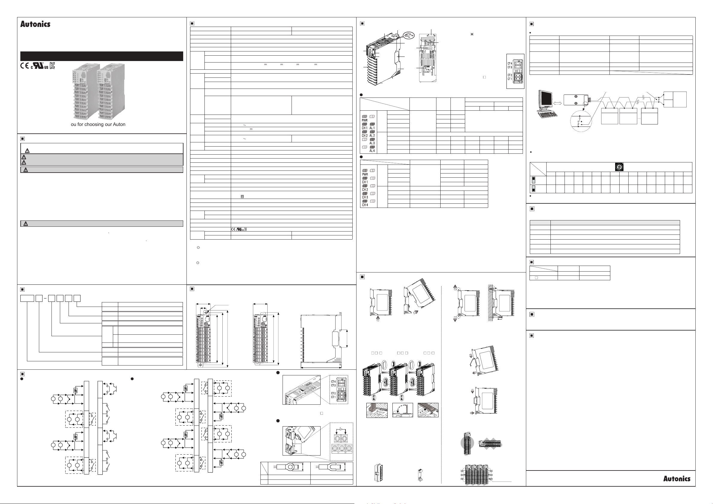
● Application of system organization
Computer
※
It is recommended to use Autonics communication converter; SCM-WF48 (Wi-Fi to RS485 USB wireless
communication converter, sold separately), SCM-US48I (USB to RS485 converter, sold separately), SCM-38I
(RS232C to RS485 converter, sold separately), SCM-US (USB to Serial converter, sold separately).
Please use twisted pair wire, which is suitable for RS485 communication, for SCM-WF48, SCM-US48I and
SCM-38I.
Communication address setting
Set the communication address with the communication address setting switch (SW1) and communication
address group switch (SW2) (default: [SW1] 1, [SW2] +0).
SW1
SW2
+0
+16
+0
+16
~
Caution for communication address setting
After changing communication address via the power/comm. terminal, reboot the device.
Comprehensive Device Management Program[DAQMaster]
~
DAQMaster is a comprehensive device management software for setting parameters and
monitoring processes.
tem Minimum specications
~
System IBM PC compatible computer with Pentium Ⅲ or above
~
Operations Windows 98/NT/XP/Vista/7/8/10
'
Memory 256MB+
~
Hard disk 1GB+ of available hard disk space
VGA Resolution: 1024×768 or higher
Others RS232C serial port (9-pin), USB port
Error Display
00
Indicator
PRW ON (red) ON (green)
※
3
CH
※
1: Input error: input value is below the input range (LLLL) / input value exceeds input range (HHHH) / input
sensor wire is down or input sensor is disconnected (OPEN).
※
2: Remote SV error: communication error of Remote SV master and internal communication / input of master
channel is LLLL/HHHH/OPEN when the channel is subjected to display PV.
※
3: An indicator of relative channel flashes.
After main cause of the error is solved, error status is cleared and the device is returned to the normal
operation automatically
Manuals
For the detail information and instructions, please refer to user manual and user manual for communication,
and be sure to follow cautions written in the technical description (catalog, homepage).
Cautions during Use
00
1. Follow instructions in 'Cautions during Use'. Otherwise, t may cause unexpected accidents.
2. Check the polarity of the terminals before wiring the temperature sensor.
For RTD temperature sensor, wire it as 3-wire type, using cables in same thickness and length.
For thermocouple (CT) temperature sensor, use the designated compensation wire for extending wire.
3. Keep away from high voltage lines or power lines to prevent inductive noise.
In case installing power line and input signal line closely, use line filter or varistor at power line and shielded
wire at input signal line.
Do not use near the equipment which generates strong magnetic force or high frequency noise.
4. Do not apply excessive power when connecting or disconnecting the connectors of the product.
5. Install a power switch or circuit breaker in the easily accessible place for supplying or disconnecting the power.
6. Do not use the unit for other purpose (e g. voltmeter, ammeter), but temperature controller.
7. When changing the input sensor, turn off the power first before changing.
After changing the input sensor, modify the value of the corresponding parameter.
8. Power supply should be insulated and limited voltage/current or Class 2, SELV power supply device.
9. Do not overlapping communication line and power line.
Use twisted pair wire for communication line and connect ferrite bead at each end of line to reduce the effect
of external noise.
10. Make a required space around the unit for radiation of heat.
For accurate temperature measurement, warm up the unit over 20 min after turning on the power.
11. Mounting multiple devices in any way other than the specified mounting method may cause heat to build
up inside, which will shorten their service life. If there is a possibility of the ambient temperature rising to a
temperature above the specified temperature range, take steps, such as installing fans, to cool the device.
Be sure that the cooling method in not cooling just the terminal block. If only the terminal block is cooled,
measurement errors may occur.
12. Make sure that power supply voltage reaches to the rated voltage within 2 sec after supplying power.
13. Do not wire to terminals which are not used.
14. Install DIN rail vertically from the ground.
15. This unit may be used in the following environments.
Indoors (in the environment condition rated in 'Specifications')
①
Altitude max. 2,000m
②
Pollution degree 2
③
Installation category II
④
Modbus RTU
EIA RS485 Compliance with Start bit 1-bit (xed)
32 units (address: 01 to 32)
(in case connecting TMHC module:
16 units (address: 01 to 16))
Asynchronous Parity bit None (default), Odd, Even
Max. 800m
RS232C/
USB/Wi-Fi
Comm.
converter
0 1 2 3 4 5 6 7 8 9 A B C D E F
16 01 02 03 04 05 06 07 08 09 10 11 12 13 14 15
32 17 18 19 20 21 22 23 24 25 26 27 28 29 30 31
111
Status
Input error
Flash (red) Flash (red)
RS485
B (-)
ON OFF
A (+)
II
※
1
Remote SV error
Comm. speed
Response waiting time
Data bit 8-bit (xed)
Terminating resistance
(100 to 120Ω)
A (+) B (-) A (+) B (-) A (+) B (-)
RS485
DEVICE
#1
11i1
※
2
4800, 9600 (default), 19200, 38400, 115200 bps
5 to 99ms (default: 20ms)
※
Only for RS485 communication output model.
RS485
DEVICE
#2
RS485
DEVICE
#30
II
B (-)
A (+)
I
II
Autonics
RS485
DEVICE
#31
I I
 Loading...