

Autonics MP5S Series, MP5Y Series, MP5W Series Catalog Page
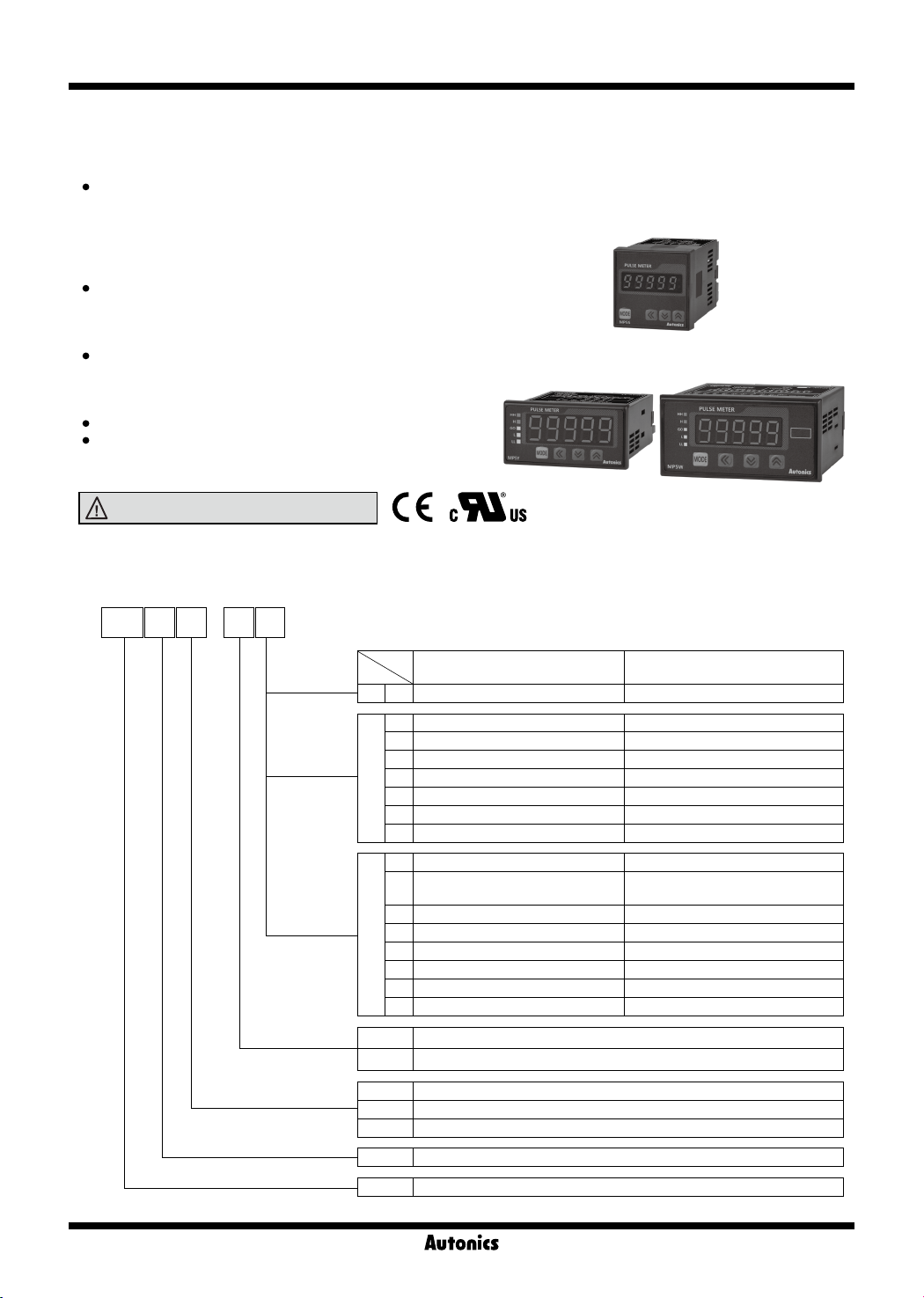
MP5S/MP5Y/MP5W Series
-|Transparent setting guide|-
High Performance, Digital Pulse Meter
Features
▣
Total 16 types of operation mode
Frequency/Revolutions/Speed, Passing speed, Cycle, Passing time,
Time interval, Time dierential , Absolute ratio, Error ratio, Density,
Error, Length measurement 1, Length measurement 2, Interval,
Accumulation, Addition/Subtraction-individual input, Addition/
Subtraction-phase dierence input
Various output models
Relay triple/quintuple output, NPN/PNP open collector quintuple output,
BCD dynamic output, PV transmission output (current output),
RS485 communication output (Modbus RTU)
Various functions
Selectable NPN solid state/contact input, PNP solid state/contact
input, prescale, delay monitoring, hysteresis, auto-zero time
setting, lock setting, data bank function (MP5W series)
Max. display range: -19999 to 99999
Various display units
rpm, rps, Hz, kHz, sec, min, m, mm, mm/s, m/s, m/min, m/h, ℓ/s,
ℓ/min, ℓ/h, %, counts, etc.
Please read “Safety Considerations”
in the instruction manual before using.
MP5S
MP5Y MP5W
▣ Ordering Information
-
MP 5 Y 4
Size
Digits
Item
N
Output
Power supply
Main output
(comparative value output)
S N Indicator
N Indicator
1 NPN open collector quintuple output
2 PNP open collector quintuple output
Y
3 Indicator BCD dynamic output
4 Indicator PV transmission output (current output)
5 Indicator RS485 communication output
6 Relay triple output (H, GO, L)
N Indicator
Relay quintuple output
A
(HH, H, GO, L, LL)
1 Relay triple output (H, GO, L)
2 NPN open collector quintuple output BCD dynamic output
W
4 NPN open collector quintuple output PV transmission output (current output)
5 PNP open collector quintuple output PV transmission output (current output)
8 NPN open collector quintuple output RS485 communication output
9 PNP open collector quintuple output RS485 communication output
2 24VAC 50/60Hz, 24-48VDC
4 100-240VAC 50/60Hz
S DIN W48×H48mm
Y DIN W72×H36mm
W DIN W96×H48mm
5 99999 (5-digit)
MP Pulse meter
Sub output
(display value output)
-
-
-
-
-
-
-
-
O-76
Pulse Meter
-|Transparent setting guide|-
Specications
▣
Series MP5S MP5Y MP5W
Display method 7-segment LED (zero blanking method)
Character size W4×H8mm W7×H14mm
Display range -19999 to 99999
Power
supply
Power
consumption
Permissible voltage range 90 to 110% of rated voltage
External power supply Max. 12VDCᜡ ±10% 80mA
Sub power supply
Input frequency
Input method
Measurement range
Measurement accuracy
(23℃±5℃)
Display cycle OFF (for F2, F16 operation mode), 0.05, 0.5, 1, 2, 4, 8 sec (same as update output cycle)
Operation mode
Prescale function Direct input method (0.0001×10
Hysteresis 0 to 9999
Output
Memory retention Non-volatile memory (number of inputs: 100,000 operations)
Insulation resistance Over 100MΩ (at 500VDC megger)
Dielectric strength 2,000VAC 60Hz for 1 min
Noise immunity ±2kV the square wave noise (pulse width: 1㎲) by the noise simulator
Vibration
Shock
Relay
life cycle
Environ-
ment
Approval
Weight
※
1: Setting range will vary depending on the decimal point.
※
2: The weight includes packaging. The weight in parenthesis is for unit only.
※
Environment resistance is rated at no freezing or condensation.
AC voltage 100-240VACᜠ 50/60Hz
AC/DC voltage 24VACᜠ 50/60Hz, 24-48VDC
AC voltage
AC/DC voltage
Max. 7.5VA
(100-240VACᜠ 50/60Hz)
Max. 6VA (24VACᜠ 50/60Hz),
max. 4.5W (24-48VDCᜡ)
-
Solid state input 1: max. 50kHz (pulse width: min. 10㎲)
·
ᜡ
Max. 9VA
(100-240VACᜠ 50/60Hz)
Max. 7VA (24VACᜠ 50/60Hz),
max. 6.2W (24-48VDCᜡ)
Max. 15VA
(100-240VACᜠ 50/60Hz)
Max. 11VA (24VACᜠ 50/60Hz),
max. 7W (24-48VDCᜡ)
Max. 24VDCᜡ 30mA
·Solid state input 2: max. 5kHz (pulse width: min. 100㎲)
※
Contact input: max. 45Hz (pulse width: min. 11ms)
·
For F7, F8, F9, F10 operation mode, max. 1kHz (pulse width: min. 500㎲)
[Voltage input] High: 4.5-24VDCᜡ, Low: 0-1VDC, Input impedance: 3.9kΩ
[No-voltage input] Short-circuit impedance: max. 80Ω, Residual voltage: max. 1VDC,
Open-circuit impedance: min. 100kΩ
·Operation m
·Operation m
·Operation m
·Operation m
·Operation m
·Operation m
ode F1, F2, F7, F8, F9, F10
ode F3, F4, F5, F6
ode F11, F12, F13, F16
ode F14, F15
ode F1, F2, F7, F8, F9, F10
ode F3, F4, F5, F6
: 0.0005Hz to 50kHz
: 0.01 to max. of each time range
: 0 to 99999
: -19999 to 99999
: F.S.±0.05%rdg±1-digit
: F.S.±0.01%rdg±1-digit
Frequency/Revolutions/Speed (F1), Passing speed (F2), Cycle (F3), Passing time (F4),
Time interval (F5), Time dierential (F6), Absolute ratio (F7), Error ratio (F8), Density (F9), Error (F10),
Length measurement 1 (F11), Interval (F12), Accumulation (F13), Addition/Subtraction-individual input (F14),
Relay triple
Relay quintuple
Main
NPN/PNP open
collector quintuple
Addition/Subtraction-phase dierence input (F15), Length measurement 2 (F16)
※
1
-
-9
to 9.9999×10⁹)
250VACᜠ 3A, 30VDCᜡ 3A resistive load
-
Max. 30VDCᜡ 30mA
250VACᜠ 3A, 30VDCᜡ 3A
resistive load
BCD dynamic Max. 30VDCᜡ 30mA
Sub
PV transmission DC4-20mA/DC0-20mA max. load 500Ω
Communication RS485 communication output (Modbus RTU method)
Mechanical 0.75mm amplitude at frequency of 10 to 55Hz in each X, Y, Z direction for 1 hour
Malfunction 0.5mm amplitude at frequency of 10 to 55Hz in each X, Y, Z direction for 10 min
Mechanical 300m/s² (approx. 30G) in each X, Y, Z direction for 3 times
Malfunction 100m/s² (approx. 30G) in each X, Y, Z direction for 3 times
Mechanical
Electrical
-
-
Ambient temp. -10 to 50℃, storage: -20 to 60
Min. 10,000,000 operations
Min. 100,000 operations (250VAC 3A resistive load)
℃
Ambient humi. 35 to 85%RH, storage: 35 to 85%RH
※
2
Approx. 191g (approx. 132g) Approx. 230g (approx. 140g) Approx. 334g (approx. 210g)
SENSORS
CONTROLLERS
MOTION DEVICES
SOFTWARE
(J)
Temperature
Controllers
(K)
SSRs
(L)
Power
Controllers
(M)
Counters
(N)
Timers
(O)
Digital
Panel Meters
(P)
Indicators
(Q)
Converters
(R)
Digital
Display Units
(S)
Sensor
Controllers
(T)
Switching
Mode Power
Supplies
(U)
Recorders
(V)
HMIs
(W)
Panel PC
(X)
Field Network
Devices
O-77
MP5S/MP5Y/MP5W Series
-|Transparent setting guide|-
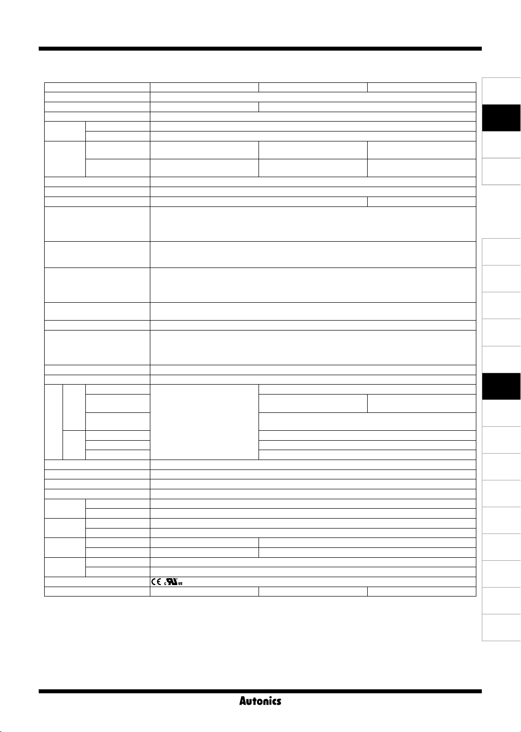
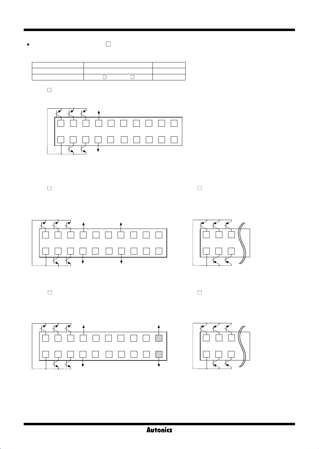
▣ Connections
※
Terminal connections dier by power supply and output type of each series and model.
MP5S Series
※
1: Operation mode F1 to F12
: display value HOLD
Operation mode F13 to F16
: display value RESET
※
2:
Model Source
MP5S-2N
MP5S-4N
24-48VDC
24VAC 50/60Hz
100-240VAC
50/60Hz
MP5Y Series
Power/Input Terminal (Common)
※
MP5Y-
N (indicator) only has 'Power/Input terminals'.
Black Black Blue Brown
1 2 3 4 5 6 7
INA INB
Black
INA
6 7 8 9 10
11
HOLD/RESET
Black
INB
0V +12V
※
1
Brown
+12V
Blue
0V
SOURCE
+-
SOURCE
HOLD/RESET
12
54321
+-
※
2
※
2
※
1
※
1: Operation mode F1 to F12
: display value HOLD
Operation mode F13 to F16
: display value RESET
※
2:
Model Source
MP5Y-2
MP5Y-4
24-48VDC
24VAC 50/60Hz
100-240VAC
50/60Hz
Output Connector (MP5Y-
※
Hirose connector: HIF3BA-10PA-2.54DS
※
Connector socket specification: Contact the manufacture for the socket and cable.
Connector socket HIF3BA-10D-2.54R Hirose Electric
MP5Y-
●
1 (NPN open collector output)
MAIN OUT (NPN OPEN COLLECTOR)
30VDC 30mA
HH
COM H L
Specifications Manufacture
GO LL
2 4 6 8
1 3 5 7
10
9
O-78
1 to 5)
MP5Y-
●
2 (PNP open collector output)
MAIN OUT (PNP OPEN COLLECTOR)
30VDC 30mA
GO LL
HH
2 4 6 8
1 3 5 7
COM H L
10
9
Pulse Meter
-|Transparent setting guide|-
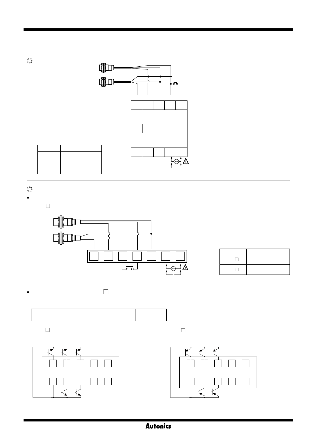
MP5Y-
●
3 (BCD dynamic output)
BCD OUT (NPN OPEN COLLECTOR)
30VDC 30mA
A
C D0 D4D2
2 4 6 8
1 3 5 7
COM B D
※
Autonics display unit (DS/DA Series) is recommended
D1 D3
10
9
for stable minus (-) sign display.
MP5Y-
●
5 (RS485 communication otuput)
RS485 B(-)
2 4 6 8
1 3 5 7
10
9
RS485 A(+)
MP5W Series
●Power/Input Terminal (Common)
※
MP5W-
N (indicator) only has 'Power/Input terminals'.
MP5Y-
●
4 (PV transmission output)
DC4-20mA/DC0-20mA
Load 500Ω Max.
2 4 6 8
1 3 5 7
(+)
10
9
(-)
●Output Terminal (MP5Y-
MP5Y-
●
6 (Relay triple output)
6)
8 9 10 11 12 13 14 15
H GO L
CONTACT OUT:
250VAC 3A, 30VDC 3A RESISTIVE LOAD
SENSORS
CONTROLLERS
MOTION DEVICES
SOFTWARE
(J)
Temperature
Controllers
(K)
SSRs
(L)
Power
Controllers
(M)
Counters
(N)
Timers
(O)
Digital
Panel Meters
Black Black Blue Brown
※
1: Operation mode F1 to F12
: display value HOLD
Operation mode F13 to F16
: display value RESET
※
2:
Model Source
MP5W-2
MP5W-4
●Output Terminal (MP5W-
MP5W-
●
24-48VDC
24VAC 50/60Hz
100-240VAC
50/60Hz
A/1)
A (Relay quintuple output)
CONTACT OUT:
250VAC 3A, 30VDC 3A RESISTIVE LOAD
10 11 12 13 14 15
HH
H GO L LL COM
1
INA INB
2
3 4 5 6 7 8 9
※
1
MP5W-
0V +12V
1 (Relay triple output)
0V
HOLD/RESET
BANK
●
CONTACT OUT:
250VAC 3A, 30VDC 3A RESISTIVE LOAD
H GO L
10 11 12 13 14 15
+-
SOURCE
(P)
Indicators
(Q)
Converters
(R)
Digital
Display Units
(S)
※
2
Sensor
Controllers
(T)
Switching
Mode Power
Supplies
(U)
Recorders
(V)
HMIs
(W)
Panel PC
(X)
Field Network
Devices
O-79
MP5S/MP5Y/MP5W Series
-|Transparent setting guide|-
Output Connector (MP5W-
※
Hirose connector: HIF3BA-20PA-2.54DS
※
Connector socket specification: Contact the manufacture for the socket and cable.
Connector socket HIF3BA-20D-2.54R Hirose Electric
I/O cable (sold separately) CO20-HP
MP5W-
●
2 (NPN open collector+BCD dynamic output)
MAIN OUT (NPN OPEN COLLECTOR)
30VDC 30mA
HH
GO
2 4 6 8
1113135157
COM H L
※
1: Sub power supply
※
POL signal turns ON when the display value is a minus (-) value.
2:
※
Autonics display unit (DS/DA Series) is recommended for stable minus (-) sign display.
MP5W-
●
4
Specifications Manufacture
+24VDC
30mA Max.
LL
2/4/5/8/9)
-L, CO20-HP -R Autonics
※
1
D
B D3
10 12 14 16 18 20
A D2
0V
D1
C D4D0 POL
BCD OUT (NPN OPEN COLLECTOR)
30VDC 30mA
DOT COM2
17919
※
MP5W-
●
(NPN open collector+PV transmission output)
MAIN OUT (NPN OPEN COLLECTOR)
30VDC 30mA
HH
GO LL
2 4 6 8
+24VDC
30mA Max.
※
1
(+)
10 12 14 16 18 20
2
5
(PNP open collector+PV transmission output)
MAIN OUT (PNP OPEN COLLECTOR)
30VDC 30mA
GO
LL
HH
2 4 6
1113135157
COM H L
MP5W-
●
8
(NPN open collector+RS485 comm. output)
MAIN OUT (NPN OPEN COLLECTOR)
30VDC 30mA
HH
GO LL
2 4 6 8
1113135157
COM H L
0V
+24VDC
30mA Max.
0V
(-)
DC4-20mA/DC0-20mA
(Load 500Ω Max.)
※
1
10 12 14 16 18
9
17919
RS485
B(-)
20
17
19
A(+)
RS485
1 3 5
COM
MP5W-
●
9
(PNP open collector+RS485 comm. output)
MAIN OUT (PNP OPEN COLLECTOR)
30VDC 30mA
HH
GO
L
H
LL
2 4 6
1 3 5
COM H L
O-80
-|Transparent setting guide|-
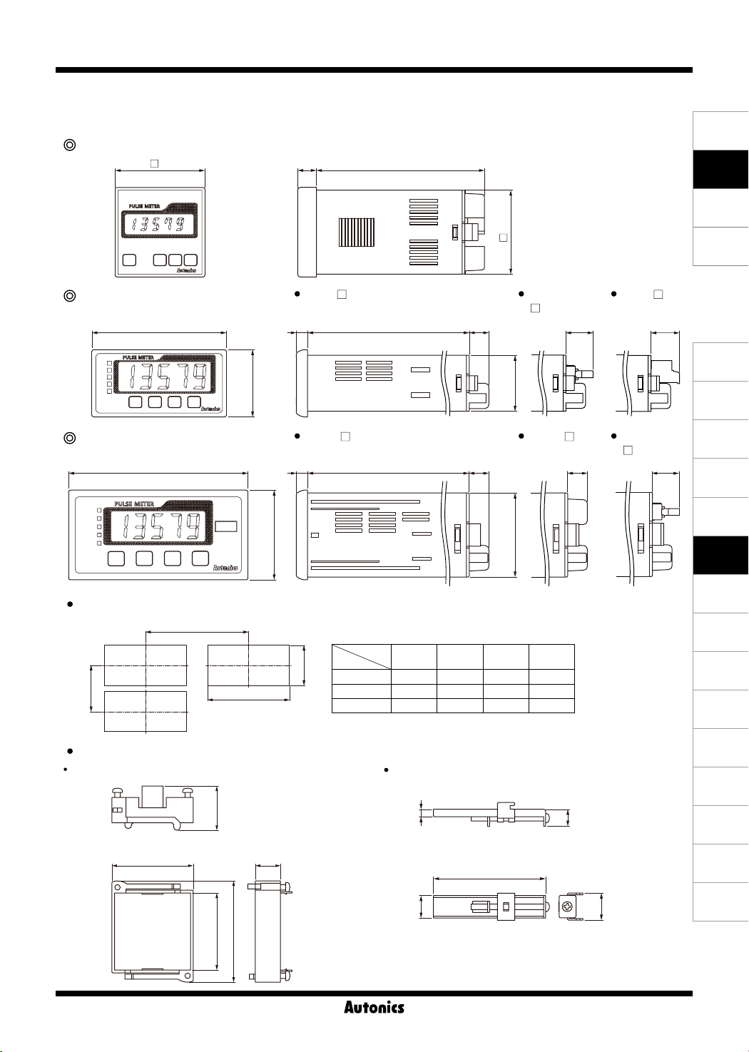
Dimensions
▣
※
Side dimensions of MP5Y/W dier by output type.
MP5S Series
48
Pulse Meter
(unit: mm)
SENSORS
9010
45
CONTROLLERS
MOTION DEVICES
SOFTWARE
MP5Y Series
MP5Y- N MP5Y
6
89.5
36
MP5W Series
96
MP5W- N MP5W- A/1
6
89.5
48
Panel cut-out
A
Size
Series
D
B
C
MP5S Min. 55 Min. 62 45.5
MP5Y Min. 91 Min. 40 68
MP5W Min. 116 Min. 52 92
Bracket
For MP5S For MP5Y/W
A B C D
10.5
10.5
+0.5
0
+0.7
0
+0.8
0
- 1/2/3/4/5
30
45
(unit: mm)
45.5
31.5
+0.6
45
0
MP5Y- 6
15.314.572
(J)
Temperature
Controllers
(K)
SSRs
14.5
(L)
Power
Controllers
(M)
Counters
(N)
Timers
(O)
Digital
Panel Meters
(P)
Indicators
(Q)
Converters
(R)
Digital
Display Units
(S)
Sensor
Controllers
(T)
Switching
Mode Power
Supplies
(U)
Recorders
MP5W
- 2/4/5/8/9
10.5
+0.5
0
+0.5
0
26.3
48.3 15
60.2
□45.8
4.4
12
10
73
14.5
(V)
HMIs
(W)
Panel PC
(X)
Field Network
Devices
O-81

MP5S/MP5Y/MP5W Series
-|Transparent setting guide|-
▣ Unit Description
MP5S Series
MP5S Series
4
MP5S Series
4
1
2 3
1: Display component
Displays current value in RUN mode.
Alternately displays setting parameters and corresponding value in SETTING mode.
2:
key
In RUN mode, press the key once to check max./min. value.
In RUN mode, hold the key for over 2 sec to enter parameter groups.
3:
, , key
Select parameter groups, and select or setting values in the corresponding parameters.
4: Output status indicator
Sold Separately
▣
2
3
1
Communication converter
SCM-WF48
( Wi-Fi to RS485·USB wireless
communication converter)
SCM-US48I
(USB to RS485 converter)
Display Units (DS/DA-T Series)
DS/DA-T Series
(RS485 communication input type display unit)
2
3
SCM-38I
(RS232C to RS485 converter)
1
DS16- T DS22/DA22- T DS40/DA40- T DS60/DA60- T
※
Connect RS485 communication input type display unit (DS/DA-T Series) and RS485 communication output model of MP5Y/MP5W Series,
the display unit displays present value of the device without PC/PLC.
▣ Input Specications
1. Input signal
Standard duty ratio of input signal is 1:1.
(1) Solid state input 1
Input frequency: Max. 50kHz (ON/OFF pulse width: min. 10㎲ of each)
(2) Solid state input 2
Input frequency: Max. 5kHz (ON/OFF pulse width: min. 100㎲ of each)
※
For F7, F8, F9, F10 operation mode, max. 1kHz (ON/OFF pulse width: min. 500㎲ of each)
(3) Contact input
Input frequency: Max. 45Hz (when each ON/OFF pulse width is over 11ms)
①
Contact specications: 12VDC, stable switching of load current as small as 5mA
②
2. Input type [
MP5 allows selection between NPN input (solid state/contact) or PNP input (solid state/contact).
(1) NPN input type (2) PNP input type
Contact
①
IN-A, IN-B
NPN voltage
②
output type sensor
Sensor circuit
]
NPN open collector
③
output type sensor
+12V
(COM)
Sensor circuit
IN
0V
O-82
3.9kΩ
MP5
Sensor circuit
Contact② PNP voltage
①
output type sensor
Sensor circuit
ON
OFF
※
PNP open collector
③
output type sensor
Sensor circuit
Pulse width
OFF
ON
T
T: single cycle of input signal
+12V
IN
0V
(COM)
MP5
3.9kΩ
Sensor circuit
-|Transparent setting guide|-
▣ Output Specications
1. Relay output
Output: Comparative or alarm output (refer to "
①
Output type: Relay
②
Contact capacity: 250VAC 3A resistive load
③
Life cycle: [Mechanical] min. 10,000,000 operations (switching frequency 180 operations/min)
④
[Electrical] min. 100,000 operations (3A 250VAC, 30VDC resistive load) (switching frequency 20 operations/min)
2. Transistor output
Output: Comparative output or alarm output (refer to "
①
Output type: NPN/PNP open collector
②
Rated load voltage: 30VDC
③
Max. load current: 30mA
④
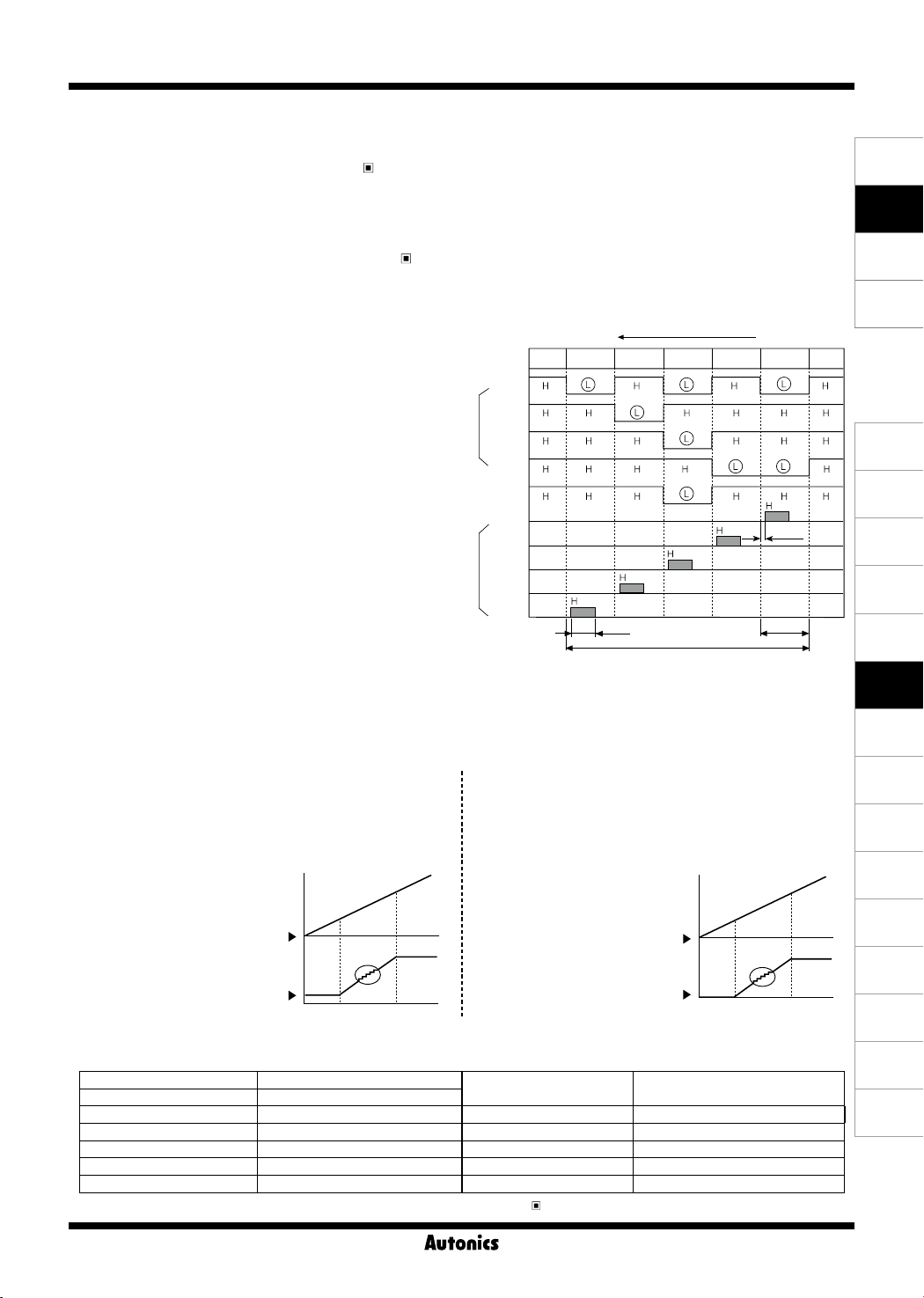
3. BCD dynamic output (negative logic)
Output: present value
①
Output signal: BCD data (A, B, C, D, DOT)
②
← A: lowest bit, DOT: highest bit
Digit data (D0, D1, D2, D3, D4)
← D0: lowest digit, D4: highest digit
Output type: NPN open collector
③
Rated load voltage: 30VDC
④
Max. load current: 30mA
⑤
Dynamic COM cycle (T) = 40ms
⑥
4. PV transmission output
Application: transmit measured value
①
Function: transmit measured value within setting range of high-limit output [
②
Output range of high/low-limit
③
·
·
(1) DC4-20mA transmission output
Transmit measured value within setting range of high-limit
①
output [
into DC4-20mA current.
Resistive load: Max. 500Ω
②
Resolution: 8000 divisions
③
If the setting width between [
[
FS-H
DC4-20mA or DC0-20mA current.
High-limit [
Low-limit [
] is lower than 8000 divisions, the
FS-H
] range: From min. value to max. value within measurement range
FS-L
] range: From min. value to max. value within measurement range ([
FS-H
] to low-limit output [
Set [
] and [
FS-L
the output is DC4-20mA.
FS-H
FS-L
] and
] and
resolution is also reduced.
FS-L
FS-L
4mA
Output Modes")
] after conversion
Diplay value
FS-H
20mA
Output Modes")
E.g.) To display value = 125.89 by BCD dynamic output
PV display value
BCD
Data
Digit
(2) DC0-20mA transmission output
①
②
③
If the setting width between [
[
A
B
C
D
DOT
D0
D1
D2
D3
D4
FS-H
] to low-limit output [
Transmit measured value within setting range of high-limit
FS-H
output [
DC0-20mA current.
Resistive load: Max. 500Ω
Resolution: 10,000 divisions
Set [
] is lower than 10,000 divisions,
FS-H
the resolution is also reduced.
Pulse Meter
4
-digit 100-digit
10
1 2 5. 8 9
5ms
FS-H
FS-L
]≥[
] to low-limit output [
] and [
FS-L
the output is DC0-20mA.
FS-H
FS-L
40ms
FS-L
] after conversion into
]+1)
FS-L
] and
] and
0mA
] after conversion into
FS-L
0.1ms
8ms
Display value
FS-H
20mA
SENSORS
CONTROLLERS
MOTION DEVICES
SOFTWARE
(J)
Temperature
Controllers
(K)
SSRs
(L)
Power
Controllers
(M)
Counters
(N)
Timers
(O)
Digital
Panel Meters
(P)
Indicators
(Q)
Converters
(R)
Digital
Display Units
(S)
Sensor
Controllers
(T)
Switching
Mode Power
Supplies
(U)
Recorders
(V)
HMIs
5. RS485 communication output
Comm. protocol Modbus RTU
Connection type RS485
Application standard Compliance with EIA RS485 Communication response time 5 to 99ms (default: 20ms)
Max. connection 31 units (address: 01 to 99) Start Bit 1-bit xed
Synchronous method Asynchronous Data Bit 8-bit xed
Comm. method Two-wire half duplex Parity Bit None (default), Even, Odd
Comm. distance Max. 800m Stop Bit 1, 2-bit (default)
※
For more information about RS485 communication output specications, refer to '
Communication Speed
RS485 Communication Output'.
2400, 4800, 9600 (default), 19200,
38400 bps
O-83
(W)
Panel PC
(X)
Field Network
Devices
 Loading...