

Autonics MD5 Series Catalog Page
MD5 Series
Model
MD5-HD14
MD5-HF14
MD5-HF14-AO
MD5-HF28
MD5-ND14
Power supply
20-35VDC
※
1
100-220VACᜠ 50/60Hz
20-35VDC
※
1
Allowable voltage range
90 to 110% of the rated voltage
Max. current consumption
※
2
3A5A3A
RUN current
※
3
0.4-1.4A/Phase
1.0-2.8A/Phase
0.5-1.5A/Phase
STOP current
27 to 90% of RUN current (set by STOP current switch)
25 to 75% of RUN
current volume)
Drive method
Bipolar constant current pentagon drive
Basic step angle
0.72˚/step
Resolution
1, 2, 4, 5, 8, 10, 16, 20, 25, 40, 50, 80, 100, 125, 200, 250-division (0.72 to 0.00288/Step)
1, 2-division (0.72, 0.36 /step)
Min. 1
Min. 10㎲ (CW, CCW),
Min. 1ms (HOLD OFF)
50% (CW, CCW)
Below 130ns (CW, CCW)
[H]: 4-8VDCᜡ, [L]: 0-0.5VDC
7.5-14mA (CW, CCW), 10-16mA (HOLD OFF, DIVISION SELECTION, ZERO OUT)
※
4
Max. 500kHz (CW, CCW)
Input resistance
270Ω (CW, CCW),
390Ω (HOLD OFF, DIVISION SELECTION),
10Ω (ZERO OUT)
270Ω (CW, CCW),
390Ω (HOLD OFF),
10Ω (ALARM)
270Ω (CW, CCW),
10Ω (ZERO OUT)
Insulation resistance
Over 100MΩ (at 500VDC megger, between all terminals and case)
Dielectric strength
1000VAC 50/60Hz for 1min (between all terminals and case)
Noise immunity
±500V the square wave
noise (pulse width: 1μs)
by the noise simulator
±2kV the square wave noise (pulse wid h: 1μs) by the noise simulator
±500V the square wave
)
by the noise simulator
Vibration
Mechanical
1.5mm amplitude at frequency 5 to 60Hz (for 1 min) in each X, Y, Z direc ion for 2 hours
Malfunction
1.5mm amplitude at frequency 5 to 60Hz (for 1 min) in each X, Y, Z direc ion for 10 min
Environment
0 to 40℃,
storage: -10 to 60℃
0 to 50
0 to 40℃,
storage: -10 to 60℃
Ambient humi.
35 to 85%RH, storage: 35 to 85%RH
Approval
ᜢ
ᜢ ᜧ
ᜢ ᜧ
Weight
Approx. 327.5g
(approx. 220g)
Approx. 840g
(approx. 680g)
Approx. 820g
(approx. 660g)
Approx. 1.35kg
(approx. 1.2kg)
Approx. 183g
(approx. 130g)
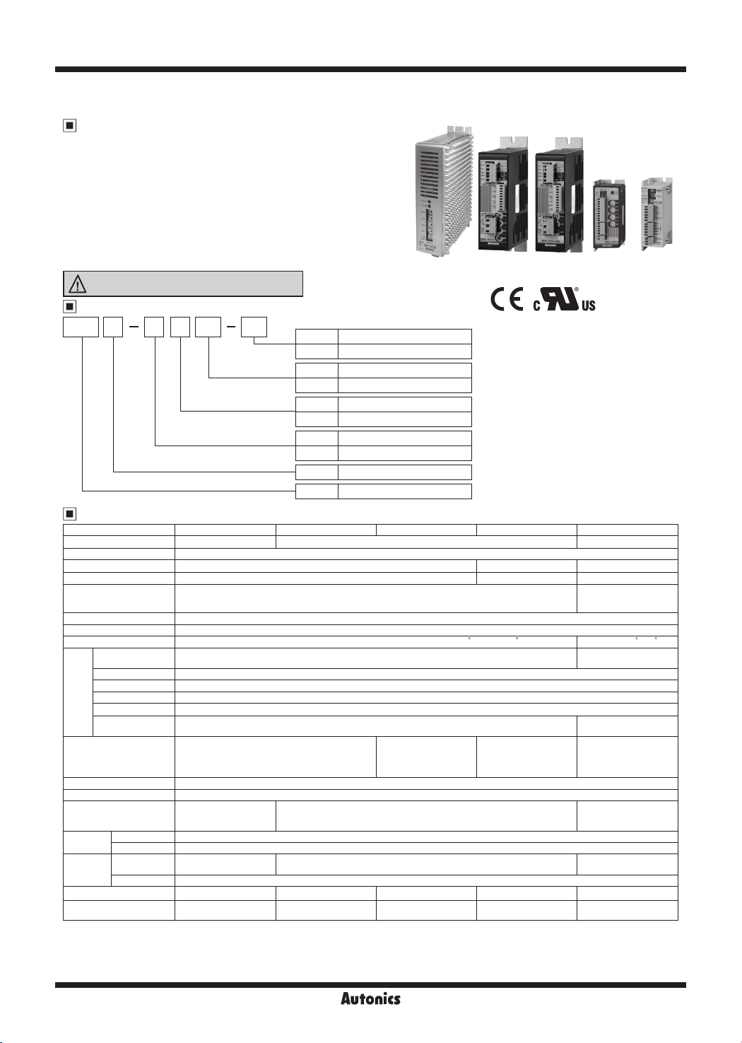
Small, Light, High Speed & Torque 5-Phase Stepper Motor Driver
Features
● Bipolar constant pentagon drive method
● Includes auto current down and self-diagnosis function
● Low speed rotation and high accuracy controlling with
microstep-driving (MD5-HD14, MD5-HF14, MD5-HF14-AO,
MD5-HF28)
[Max. resolution 250 division: In case of 5-phase stepper motor of
which basic step angle is 0.72°, it enables to control up to 0.00288°
per pulse and it requires 125,000 pulses per rotation.]
● Photocoupler input insulation method to minimize the
eects from external noise
Please read “Safety Considerations”
in the instruction manual before using.
Ordering Information
MD 145 H F
Step type (resolution)
Motor phase
Item
※
1: Except MD5-ND14
Specifications
~
RUN current
Power supply
ᜡ
No mark Zero point excitation output
Output
AO Alarm output
14 1.4A/Phase
28 2.8A/Phase
D 20-35VDC
F 100-220VAC
H Micro step (250-division)
N Normal Step
5 5-phase
MD Motor Driver
I
I
※
1
MD5-HF14
※
※
※
※
MD5-HF14-AO
(only for MD5-HF14(-AO),
MD5-HF28 model)
KR-55MC can be replaced with MD5-HD14.
KR-5MC can be replaced with MD5-ND14.
MD5-MF14 can be replaced with MD5-HF14.
KR-505G can be replaced with MD5-HF28.
I
MD5-HF28
I
MD5-HD14
ᜡ
MD5-ND14
Pulse wid h
Duty rate
Rising/Falling ime
Pulse input voltage
Pulse input current
Input pulse
characteristic
Max. input pulse
frequency
※
5
㎲ (CW, CCW), Min. 1ms (HOLD OFF)
I
Ambient temp.
※
6
1: When using over 30VDC power supply, torque characteristics are improved but the driver temperature raise. The unit should be installed at the well ventilation
※
environment.
2: Based on ambient temperature 25℃, ambient humidity 55%RH.
※
3: RUN current varies depending on the input RUN frequency and max. RUN current at the moment varies also varies depending on the load.
※
4: In case of MD5-HF14-AO, MD5-ND14, there are no DIVISION SELECTION, ZERO OUT function.
※
5: Max. input pulse frequency is max. frequency to be input and is not same as max. pull-out frequency or max. slewing frequency.
※
6: The weight includes packaging. The weight in parenthesis is for unit only.
※
AA-4
℃, storage: -10 to 60℃
I
I
I
Autonics
I
I
current (set by STOP
Max. 50kHz (CW, CCW)
390Ω (HOLD OFF,
DIVISION SELECTION),
390Ω
(CW, CCW, HOLD OFF)
noise (pulse width: 1μs
I
ᜢ ᜧ ᜢ
I
I
Environment resistance is rated at no freezing or condensation.
※
I
I
I
I
5-Phase Stepper Motor Driver (1.4A/Phase, DC Power)
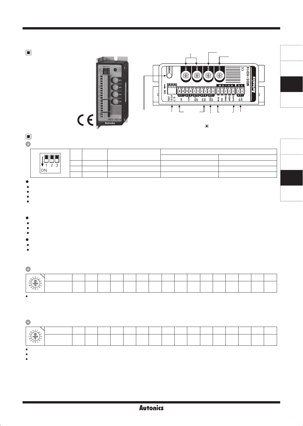
5-Phase Micro Stepper Motor Driver [MD5-HD14]
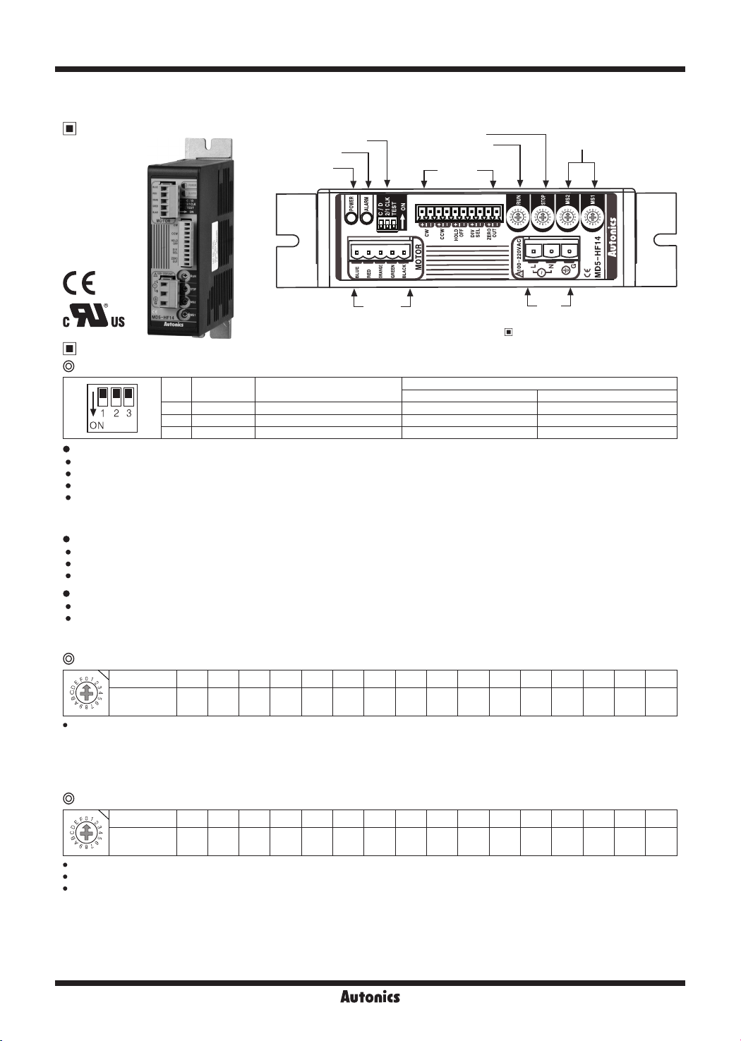
Unit Description
Resolution switch
RUN current switch
STOP current switch
SENSORS
CONTROLLERS
MOTION DEVICES
SOFTWARE
Input
terminal
Refer to
※
Motor
Zero
connection
output
terminal
'
Specifications'
Power
terminal
.
Power indicator
Functions
~
@
Function selection DIP switch
No. Name Function
l~!~~~--------r--~
TEST
•
Self diagnosis function is for motor and driver test.
•
This function makes the motor rotate with 30rpm in full step. Rotation speed varies with resolution settings.
•
Rotation speed = 30rpm/resolution
•
In 1-pulse input method, it rotates to CCW, and in 2-pulse input method, it rotates to CW.
•
※
Be sure that the TEST switch is OFF before supplying the power.
If the TEST switch is ON, he motor operates immediately and it may be dangerous.
1/2 CLK
•
1/2 CLK switch is to select pulse input method.
•
1-pulse input method: CW → operating rotation signal input, CCW → rotation direction signal input ([H]: CW, [L]: CCW)
•
2-pulse input method: CW → CW rotation signal input, CCW → CCW rotation signal input.
•
C/D (auto current down)
•
This function is to reduce the current provided for motor automatically for preventing severe motor's heat when motor stops.
•
If motor RUN pulse is not applied, the current provided for motor reduces as the set STOP current.
•
※
Be sure that when motor RUN current is reduced, the stop torque of motor also reduced.
※
Set the STOP current by the STOP current switch.
Setting RUN current
Switch No. 0 1 2 3 4 5 6 7 8 9 A B C D E F
Current
1,
Setting RUN current is for the current provided for motor when the motor runs.
•
※
※
※
※
1,
Setting STOP current is for the current provided for motor when the motor stops for preventing severe motor's heat.
•
This setting is applied when using C/D (current down) function.
•
Setting value of STOP current is percentage (%) ratio of the set RUN current.
•
E.g.) Set RUN current as 1.4A and STOP current as 40%.
※
※
※
(A/Phase)
®J I I I I I I I I I I I I I I I I I
When RUN current is increased, RUN torque of the motor is also increased.
When RUN current is set too high, the heat is severe.
Set RUN current wi hin the range of motor's rated current according to its load.
Change RUN current only when the motor stops.
Setting STOP current
Switch No. 0 1 2 3 4 5 6 7 8 9 A B C D E F
% 27 31 36 40 45 50 54 58 62 66 70 74 78 82 86 90
w,
J I I I I I I I I I I I I I I I I I
STOP current is set as 1.4A×0.4=0 56A
When STOP current is decreased, STOP torque of the motor is also decreased.
When STOP current is set too low, the heat is lower.
Change STOP current only when the motor stops.
I
.-----I---,------------,--------
1 TEST Self diagnosis function 30rpm rotation Not use
2 1/2 CLK Pulse input method 1-pulse input method 2-pulse input method
3 C/D Auto current down Not use Use
0.4 0.5 0.57 0.63 0.71 0.77 0.84 0.9 0.96 1.02 1.09 1.15 1.22 1.27 1 33 1.4
Function
selection
DIP switch
Switch position
ON OFF (default)
(Y)
Closed Loop
Stepper System
(Z)
Stepper Motors
(AA)
Drivers
(AB)
Motion
Controllers
Autonics
AA-5
MD5 Series
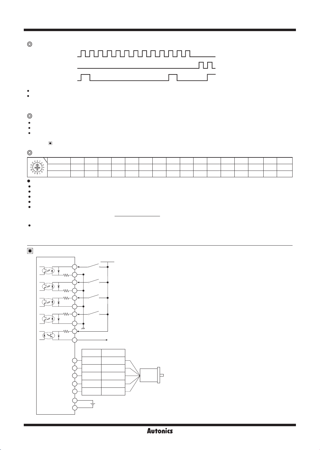
Zero point excitation output signal (ZERO OUT)
CW Pulse
CCW Pulse
ZERO OUT
This output indicates the initial step of excitation order of stepper motor and rota ion position of motor axis.
•
This signal outputs every 7.2° of rotation of the motor axis regardless of resolu ion.
•
(50 outputs per 1 rotation of the motor.)
E.g.) Full step: outputs one time by 10 pulses input, 20-division: outputs one time by 200 pulses input.
@
HOLD OFF function
This signal is for rotating motor's axis using external force or used for manual positioning.
•
When hold off signal maintains over 1ms as [H], motor excitation is released.
•
When hold off signal maintains over 1ms as [L], motor excita ion is in a normal status.
•
※
Must stop the motor for using this function.
※
Refer to '
~
@
Setting Microstep (microstep: resolution)
Switch No. 0 1 2 3 4 5 6 7 8 9 A B C D E F
1,
1 • I I I I I I I I I I I I I I I I
The MS1, MS2 switches is for resolution setting.
Select MS2 or MS2 by DIVISION SELECTION signal ([L]: MS1, [H]: MS2)
Select the step angle (motor rota ion angle per 1 pulse).
The set step angle is dividing basic step angle (0.72°) of 5-phase stepper motor by setting value.
The calculation formula of divided step angle is as below.
•
When using geared type motor, the angle is step angle divided by gear ratio.
•
※
Resolution 1 2 4 5 8 10 16 20 25 40 50 80 100 125 200 250
@J I
Step angle 0.72° 0 36° 0.18° 0.144° 0 09° 0 072° 0 045° 0.036°
Setting Resolution (same as MS1, MS2)
Step angle / gear ratio = Step angle applied gear
E.g) 0.72° / 10 (1:10) = 0.072°
Must stop the motor before changing the resolution.
ON
OFF
ON
OFF
ON
nn====~-n:__:fln
OFF
0 0 01 1 12 23 4 5 6 7 8 9
I/O Circuit and Connections'.
Set step angle =
Basic step angle (0.72°)
Resolution
,______________,
0 0288°
0.018°
0.0144°
0 009°
0.0072° 0 00576° 0 0036° 0.00288°
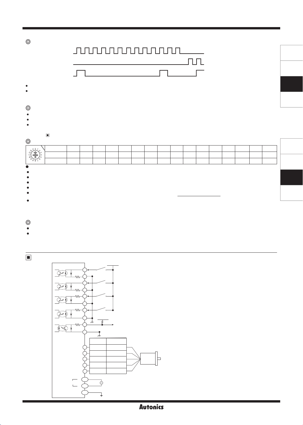
I/O Circuit and Connections
~~])~_?::-
[Signal]
JE>
""?-;;·
·•,
3----··
A;·-
..
J---·
-·
L.......J...__
[Motor]
BLUE
RED
ORANGE
GREEN
BLACK
[Power]
~-==-------
1
270Ω
2
3
270Ω
4
5
390Ω
6
7
390Ω
8
9
10Ω
10
1
2
3
4
5
1
2
+5VDC
CW
CCW
HOLD
OFF
DIVISION
SELECTION
GND
ZERO OUT
Pentagon
connection
Blue Gray+Red
Red Yellow+Black
Orange
Green Brown+Green
Black Blue+Purple
Standard
connection
Orange+White
+
Power
20-35VDC
-
※
CW
2-pulse input method (CW rota ion signal input)
1-pulse input method (operating rotation signal input)
※
CCW
2-pulse input method (CCW rotation signal input)
1-pulse input method (rotation direction signal input)
→ [H]: CW, [L]: CCW
※
HOLD OFF
Control signal for motor excitation OFF
→ [H]: Motor excitation OFF
※
DIVISION SELECTION
Division selection signal
→ [L]: Operated by MS1 setting resolution
[H]: Operated by MS2 setting resolution
※
ZERO OUT
Zero point excitation output signal → Zero point status ON
※
If the power for driving pulse from external is over
than +5VDC, please connect resistor at the outside.
(input power max. 24VDC, input current 10-20mA)
Motor
※
This connection cable color is only for Autonics motors.
It may different cable color when using other motors.
AA-6
Autonics
5-Phase Stepper Motor Driver (1.4A/Phase, DC Power)
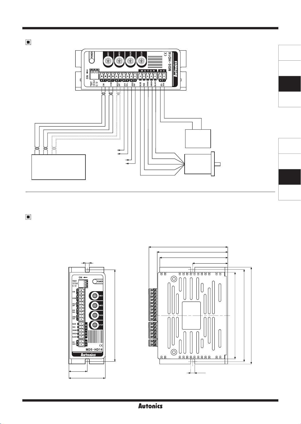
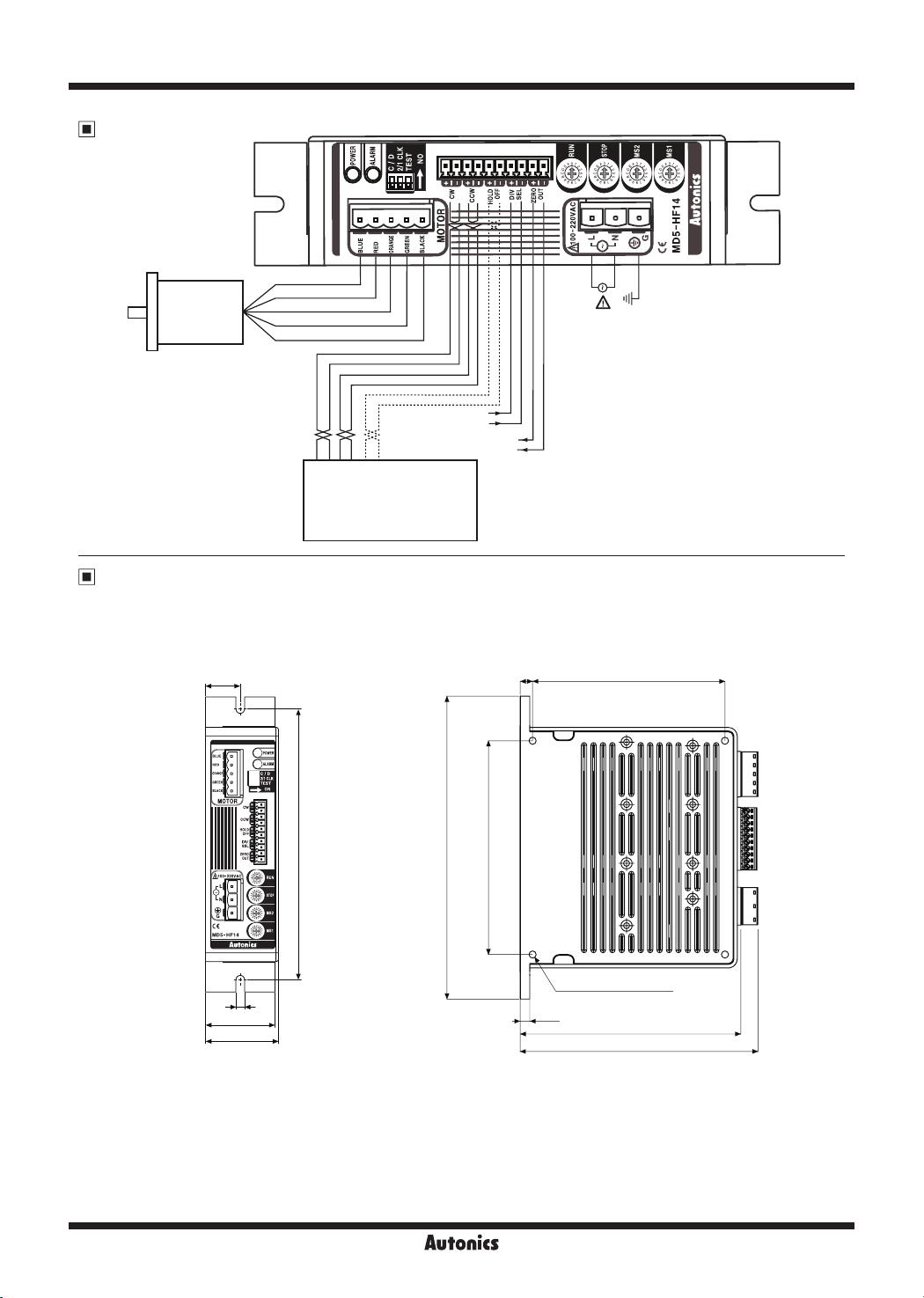
Connections
.
SENSORS
CONTROLLERS
MOTION DEVICES
SOFTWARE
(Y)
Closed Loop
Stepper System
(Z)
Stepper Motors
(AA)
Drivers
(AB)
Motion
Controllers
CW+
l
=r··---------------------------------------------------
CW-
1
CCW-
CCW+
HOLD OFF+
Controller
HOLD OFF-
User
Division selec ion
signal
Zero point
excitation
output signal
_v~
"'"
- C
= :c
='
++-
POWER
20-35VDC
+
-
-
Black
Green
Orange
Red
Blue
Motor
※
In case of standard connection,
refer to 'Stepper Motors'
section
Dimensions
~
20
4.5
MD5-HD14
39.5
(unit: mm)
86
76.5
74
38
100
(€
4.5
94
100
105
Autonics
AA-7
MD5 Series
5-Phase Micro Stepper Motor Driver [MD5-HF14]
Unit Description
Function selection DIP switch
Alarm indicator (red)
Power indicator
STOP current switch
RUN current switch
Input
terminal
Resolu ion
switch
CE:
a,®
c~us
Functions
~
@
Function selection DIP switch
l-
!~~~
r-=:
TEST
Self diagnosis function is for motor and driver test.
This function makes the motor rotate with 30rpm in full step. Rotation speed varies with resolution settings.
Rotation speed = 30rpm/resolution
In 1-pulse input method, it rotates to CCW, and in 2-pulse input method, it rotates to CW.
•
※
Be sure that the TEST switch is OFF before supplying the power.
If the TEST switch is ON, he motor operates immediately and it may be dangerous.
2/1 CLK
•
2/1 CLK switch is to select pulse input method.
•
1-pulse input method: CW → operating rotation signal input, CCW → rotation direction signal input ([H]: CW, [L]: CCW)
•
2-pulse input method: CW → CW rotation signal input, CCW → CCW rotation signal input.
•
C/D (auto current down)
•
This function is to reduce the current provided for motor automatically for preventing severe motor's heat when motor stops.
•
If motor RUN pulse is not applied, the current provided for motor reduces as the set STOP current.
•
※
Be sure that when motor RUN current is reduced, the stop torque of motor also reduced.
※
Set the STOP current by the STOP current switch.
@
Setting RUN current
1,
~J I
. I I I I I I I I I I I I I I I I
Setting RUN current is for the current provided for motor when the motor runs.
※
When RUN current is increased, RUN torque of the motor is also increased.
※
When RUN current is set too high, the heat is severe.
※
Set RUN current wi hin the range of motor's rated current according to its load.
※
Change RUN current only when the motor stops.
,:
--:-•
No. Name Function
1 TEST Self diagnosis function 30rpm rotation Not use
2 2/1 CLK Pulse input method 1-pulse input method 2-pulse input method
I I I
===------1::::::::t::==±:=~======~±==I
Switch No. 0 1 2 3 4 5 6 7 8 9 A B C D E F
Current
(A/Phase)
3 C/D Auto current down Not use Use
0.4 0.5 0.57 0.63 0.71 0.77 0.84 0.9 0.96 1.02 1.09 1.15 1.22 1.27 1 33 1.4
Motor
connection
terminal
※
Refer to '
Switch position
ON OFF (default)
~~I
Power
terminal
Specifications'.
00
~~1
@
Setting STOP current
Switch No. 0 1 2 3 4 5 6 7 8 9 A B C D E F
1,
: : I I I I I I I I I I I I I I I I
Setting STOP current is for the current provided for motor when the motor stops for preventing severe motor's heat.
This setting is applied when using C/D (current down) function.
Setting value of STOP current is percentage (%) ratio of the set RUN current.
※
※
※
AA-8
% 27 31 36 40 45 50 54 58 62 66 70 74 78 82 86 90
~J I
E.g.) Set RUN current as 1.4A and STOP current as 40%.
STOP current is set as 1.4A×0.4=0.56A
When STOP current is decreased, STOP torque of the motor is also decreased.
When STOP current is set too low, the heat is lower.
Change STOP current only when the motor stops.
Autonics
5-Phase Stepper Motor Driver (1.4A/Phase, AC Power)
Zero point excitation output signal (ZERO OUT)
CW Pulse
CCW Pulse
ZERO OUT
This output indicates the initial step of excitation order of stepper motor and rota ion position of motor axis .
•
This signal outputs every 7.2° of rotation of the motor axis regardless of resolu ion.
•
(50 outputs per 1 rotation of the motor.)
E.g.) Full step: outputs one time by 10 pulses input, 20-division: outputs one time by 200 pulses input.
@
HOLD OFF function
This signal is for rotating motor's axis using external force or used for manual positioning.
•
When hold off signal maintains over 1ms as [H], motor excitation is released.
•
When hold off signal maintains over 1ms as [L], motor excita ion is in a normal status.
•
※
Must stop the motor for using this function.
※
@
1,
1 • I
Setting Resolution (same as MS1, MS2)
The MS1, MS2 switches is for resolution setting.
Select MS2 or MS2 by DIVISION SELECTION signal ([L]: MS1, [H]: MS2)
Select the step angle (motor rota ion angle per 1 pulse).
The set step angle is dividing basic step angle (0.72°) of 5-phase stepper motor by setting value.
The calculation formula of divided step angle is as follow.
•
When using geared type motor, the angle is step angle divided by gear ratio.
•
※
@
Overheat: When the temperature of driver base is over 80
•
Overcurrent: When overcurrent occurs due to motor damage by burn, driver damage, or error, the alarm indicator (red) turns ON and the
•
※
I!]
Refer to '
Setting Microstep (microstep: resolution)
Switch No. 0 1 2 3 4 5 6 7 8 9 A B C D E F
Resolution 1 2 4 5 8 10 16 20 25 40 50 80 100 125 200 250
mJ I
Step angle 0.72° 0 36° 0.18° 0.144° 0 09° 0 072° 0 045° 0.036°
Step angle / gear ratio = Step angle applied gear
E.g) 0.72° / 10 (1:10) = 0.072°
Must stop the motor before changing the resolution.
Alarm indication
motor becomes HOLD OFF.
Turn OFF the power and remove the causes of alarm. Re-supply the power and the alarm indicator turns OFF and the driver is normal
operation.
I/O Circuit and Connections
ON
OFF
ON
OFF
ON
nn=====~n_:__:fln
OFF
0 0 01 1 12 23 4 5 6 7 8 9
I/O Circuit and Connections'.
----+----+--I
[Signal]
1
CW
2
3
CCW
4
5
HOLD
OFF
6
7
DIVISION SELECTION
+5VDC
8
9
ZERO OUT
10
Pentagon
connection
1
Blue Gray+Red
Red Yellow+Black
2
3
Orange
Green Brown+Green
4
Black Blue+Purple
5
AC
AC
G
[Power]
270Ω
270Ω
390Ω
390Ω
10Ω
[Motor]
BLUE
RED
ORANGE
GREEN
BLACK
Power
L
N
,______________,
0 0288°
0.018°
0.0144°
0 009°
I I I I I I I I I I I I I I
Basic step angle (0.72°)
Resolution
※
CW
2-pulse input method (CW rotation signal input)
1-pulse input method (operating rota ion signal input)
※
CCW
2-pulse input method (CCW rotation signal input)
1-pulse input method (rotation direction signal input)
→ [H]: CW, [L]: CCW
※
HOLD OFF
Control signal for motor excitation OFF
→ [H]: Motor excitation OFF
※
DIVISION SELECTION
Division selec ion signal
→ [L]: Operated by switch MS1
[H]: Operated by switch MS2
※
ZERO OUT
Zero point excitation output signal → Zero point status ON
※
If the power for driving pulse from external is over
than +5VDC, please connect resistor at the outside.
(input power max. 24VDC, input current 10-20mA)
+5VDC
2kΩ
Standard
connection
Orange+White
100-220VAC
50/60Hz
GND
Set step angle =
, the alarm indicator (red) turns ON and motor stops with holding the excision.
℃
Motor
※
This connection cable color is only for Autonics motors.
It may different cable color when using other motors.
0.0072° 0 00576° 0 0036° 0.00288°
SENSORS
CONTROLLERS
MOTION DEVICES
SOFTWARE
(Y)
Closed Loop
Stepper System
(Z)
Stepper Motors
<---------
(AA)
Drivers
(AB)
Motion
Controllers
Autonics
AA-9
MD5 Series
Connections
Motor
※
In case of standard connection,
refer to 'Stepper Motors' section.
Blue
Red
Orange
Green
Black
CW-
CW+
Division selection
Zero point excitation
: :
CCW-
CCW+
HOLD OFF-
HOLD OFF+
signal
output signal
User
Controller
F.G.
100-220VAC 50/60Hz
+
-
+
-
Dimensions
(unit: mm)
20
7
'
CJ
r-
'--'
108
♦
.
~
II.'../
n
I
156
170
120
I
n
I
I
--cJ,_
L::::1
\_
5
40
42
~i-----
5.4
,.-
-
4-M4 Tap Depth: 8
122
133.5
n H
□
'
□
0
AA-10
Autonics
 Loading...