

DR W171413A A
Autonics
Motor Driver (5-phase Stepper Motor Driver)
MD5-HF14
INSTRUCTION MANUAL
Thank you for choosing our Autonics product.
Please read the following safety considerations before use.
Safety Considerations
Please observe all safety considerations for safe and proper product operation to avoid
※
hazards.
symbol represents caution due to special circumstances in which hazards may occur.
※
Failure to follow these instructions may result in serious injury or death.
Warning
Caution
Warning
1. Fail-safe device must be installed when using the unit with machinery that may
cause serious injury or substantial economic loss. (e.g. nuclear power control,
medical equipment, ships, vehicles, railways, aircraft, combustion apparatus, safety
equipment, crime/disaster prevention devices, etc.)
Failure to follow this instruction may result in fire, personal injury, or economic loss.
2. Do not connect, repair, or inspect the unit while connected to a power source.
Failure to follow this instruction may result in electric shock or fire.
3. Install the unit after considering counter plan against power failure.
Failure to follow this instruction may result in personal injury, or economic loss.
4. Check 'Connections' before wiring.
Failure to follow this instruction may result in re.
For installing the unit, ground it exclusively and use over AWG 18(0.75mm2) ground cable.
5.
Failure to follow this instruction may result in electric shock.
6. Do not disassemble or modify the unit.
Failure to follow his instruc ion may result in electric shock or fire.
7. Insulate the connector not to be exposed.
Failure to follow this instruction may result in electric shock.
8. Install the driver in the housing or ground it.
Failure to follow his instruc ion may result in electronic shock, personal injury, or fire.
9. Do not touch the unit during or after operation for a while.
Failure to follow this instruction may result in electric shock or burn due to high temperature
of the surface.
10. Emergency stop directly when error occurs.
Failure to follow this instruction may result in re, or personal injury.
Caution
1. When connecting the power input, use AWG 18(0.75mm2) cable or over.
2. Install over-current prevention device (e.g. the current breaker, etc) to connect the
driver with power.
Failure to follow this instruction may result in fire.
3. Check the control input signal before supplying power to the driver.
Failure to follow this instruction may result in personal injury or product damage by
unexpected signal.
4. Install a safety device to maintain the vertical position after turn off the power of this
driver.
Failure to follow this instruction may result in personal injury or product damage by releasing
holding torque of the motor.
5. Use the unit within the rated specications.
Failure to follow this instruction may result in fire or product damage.
6. Use dry cloth to clean the unit, and do not use water or organic solvent.
Failure to follow his instruc ion may result in electric shock or fire.
7. Do not use the unit in the place where ammable/explosive/corrosive gas, humidity,
direct sunlight, radiant heat, vibration, impact, or salinity may be present.
Failure to follow this instruction may result in re or explosion.
8. The driver may overheat depending on the environment.
Install the unit in the well ventilated place and forced cooling with a cooling fan.
Failure to follow this instruction may result in product damage and degrada ion.
9. Keep metal chip, dust, and wire residue from owing into the unit.
Failure to follow this instruction may result in re or product damage.
10. Use the designated motor only.
Failure to follow this instruction may result in re or product damage.
※
The above specications are subject to change and some models may be discontinued
without notice.
※
Be sure to follow cautions written in the instruction manual and the technical
descriptions (catalog, homepage).
Failure to follow these instructions may result in personal injury or product damage.
Specications
Model MD5-HF14
Power supply 100-220VACᜠ 50/60Hz
Allowable voltage
uctuation range
Max. current
consumption
RUN current
STOP current 27 to 90% of RUN current (set by STOP current switch)
Drive method Bipolar constant current pentagon drive
Basic step angle 0.72
Resolution
Input resistance
Insulation resistance Over. 100MΩ (at 500VDC megger, between all terminals and case)
~;;;l======---=
Dielectric strength 1,000VAC 50/60Hz for 1min (between all terminals and case)
Noise resistance
Vibration
Environ-
ment
Approval
Weight
1: Based on ambient temperature 25
※
2: RUN current varies depending on the input RUN frequency and max. RUN current at the moment
※
3: Max. input pulse frequency is max. frequency to be input and is not same as max. pull-out
※
4: The weight includes packaging. The weight in parenthesis is for unit only.
※
Environment resistance is rated at no freezing or condensation.
※
00
1
※
2
※
Pulse width Min. 1μs (CW, CCW), Min. 1ms (HOLD OFF)
Duty Rate 50% (CW, CCW)
Rising/Falling time Below 130ns (CW, CCW)
Pulse input voltage
Pulse input current 7 5-14mA(CW, CCW),10-16mA(HOLD OFF, DIVISION SELECTION, ZERO OUT)
Max. input pulse
※
frequency
Input pulse characteristic
Mechanical
Malfunction
Ambient temp.
Ambient humi.
4
※
varies also varies depending on the load.
frequency or max. slewing frequency.
Dimensions
120
170
90 to 110% of the rated voltage
3A
0.4-1.4A/Phase
/Step
1, 2, 4, 5, 8, 10, 16, 20, 25, 40, 50, 80, 100, 125, 200, 250
(
0.72 to 0.00288 /Step)
[H]: 4-8VDCᜡ, [L]: 0-0 5VDC
Max. 500kHz (CW, CCW)
3
270Ω(CW, CCW), 390Ω(HOLD OFF, DIVISION SELECTION),
10Ω(ZERO OUT)
±2000V the square wave noise (pulse width: 1㎲) by the noise simulator
1 5mm amplitude at frequency of 5 to 60Hz(for 1 min.) in each X, Y, Z
direction for 2 hours
1 5mm amplitude at frequency of 5 to 60Hz(for 1 min.) in each X, Y, Z
direction for 10 min.
0 to 50℃, Storage: -10 to 60
35 to 85%RH, Storage: 35 to 85%RH
ᜢ ᜧ
Approx. 840g (approx. 680g)
7
, ambient humidity 55%RH.
℃
108
~
I
ᜡ
℃
~
I
I
I I
-division
20
""'
~
MOTORJ""
(unit: mm)
:
- .
156
V .
I
H
4-M4 Tap Depth: 8
5.4
133.5
Time Chart
00
E
1-pulse input method
[H]
CW
[L]
[H]
CCW
[L]
Rotation
position
CW CCW
2-pulse input method
[H]
CW
[L]
[H]
CCW
[L]
Rotation
position
※
Do not input CW, CCW signals at the same time in 2-pulse input method.
It may not operate properly if another direction signal is inputted when one of CW or CCW is [H].
CW CCW
122
II
◊r1
5
40
42
CW
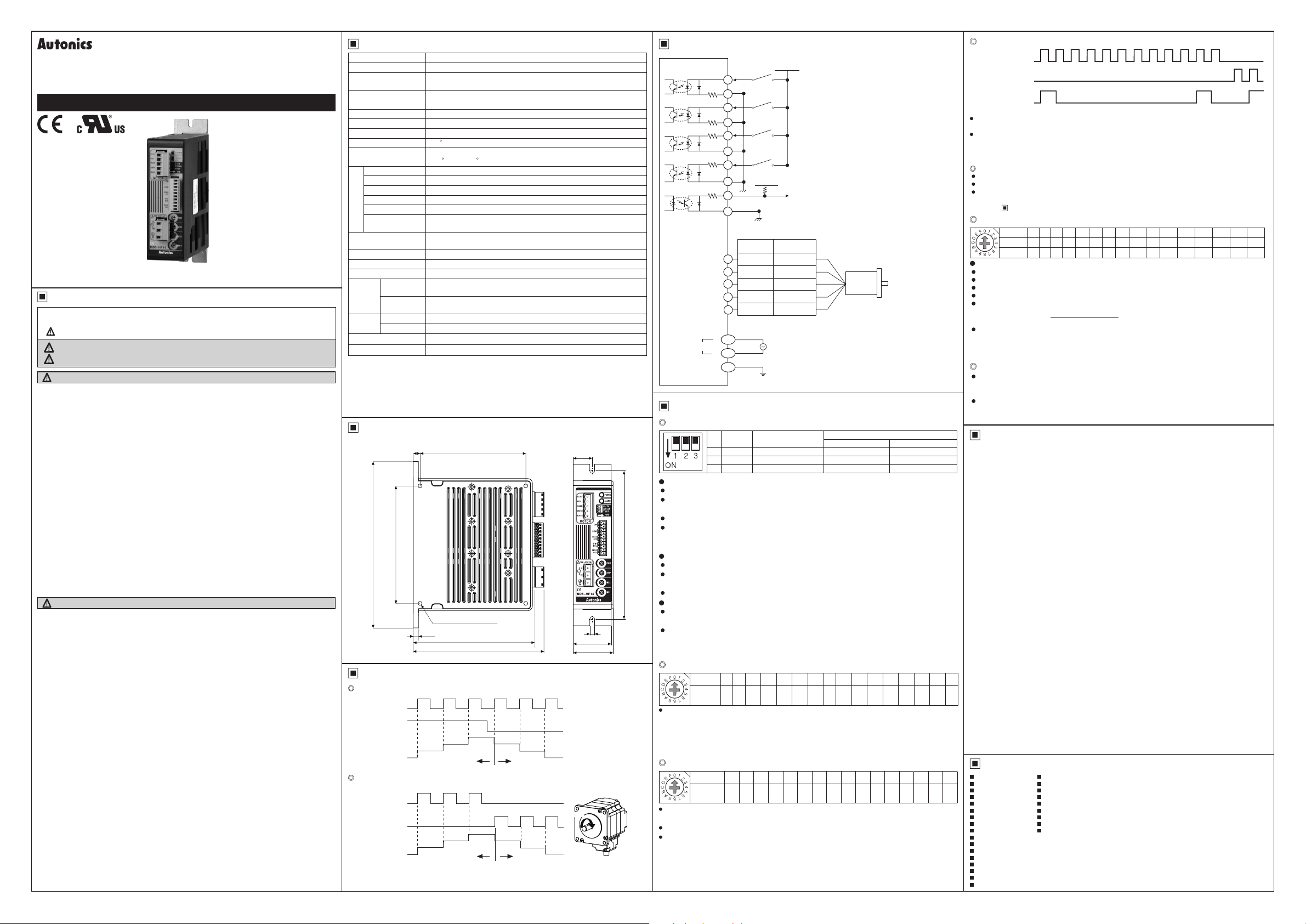
I/O Circuit and Connections
※
CW
2-pulse input method (CW rotation signal input)
1-pulse input method
※
CCW
2-pulse input method (CCW rotation signal input)
1-pulse input method (rotation direction signal input)
[H]: CW, [L]: CCW
→
※
HOLD OFF
Control signal for motor excitation OFF
→ [H]: Motor excitation OFF
※
DIVISION SELECTION
Division selection signal
→ [L]: Operated by switch MS1
[H]: Operated by switch MS2
※
ZERO OUT
Zero point excitation output signa → Zero point status ON
※
If the power for driving pulse from external is over
than +5VDC,
50/60Hz
(operating rotation signal input)
please connect resistor at the outside.
Motor
※
This connection cable color is only for
Autonics motors.
It may different cable color when
using other motors.
] :
~:
[Power]
[Signal]
r.:,-'Y'lv-:,
[Motor]
BLUE
RED
ORANGE
GREEN
BLACK
Power
270Ω
270Ω
390Ω
390Ω
10Ω
1
2
3
4
5
6
7
DIVISION SELECTION
+5VDC
8
9
-{
}--------------
ZERO OUT
10
Pentagon
connection
1
Blue Gray+Red
Red Yellow+Black
2
3
Orange
Green Brown+Green
4
Black Blue+Purple
5
L
AC
AC
N
G
CW
CCW
HOLD
OFF
+5VDC
2kΩ
Standard
connection
Orange+White
100-220VAC
GND
~-----.
Functions
00
Function selection DIP switch
©
Switch position
-1=~==1~===~
ON OFF (default)
I
0.77
0.84
0 9
0.96
1.02
1 09
1.15 1.22
1.27 1 33
0.5
0.57 0.63 0.71
-
No Name Function
1 TEST Self diagnosis function 30rpm rotation Not use
I!~~~
TEST
•
Self diagnosis function is for motor and driver test.
•
This function makes the motor rotate with 30rpm in full step. Rotation speed varies with resolution
•
settings.
Rotation speed = 30rpm/resolution
•
In 1-pulse input method, it rotates to CCW, and in 2-pulse input method, it rotates to CW.
•
Be sure that the TEST switch is OFF before supplying the power.
※
If the TEST switch is ON, the motor operates immediately and it may be dangerous.
2/1 CLK
•
2/1 CLK switch is to select pulse input method.
•
1-pulse input method: CW → operating rotation signal input,
•
2-pulse input method: CW → CW rotation signal input, CCW → CCW rotation signal input.
•
C/D (auto current down)
•
This function is to reduce the current provided for motor automatically for preventing severe motor's
•
heat when motor stops.
If motor RUN pulse is not applied, the current provided for motor reduces as the set STOP current.
•
Be sure that when motor RUN current is reduced, the stop torque of motor also reduced.
※
Set the STOP current by the STOP current setting switch.
※
Setting RUN current
©
RUN current setting is for the current provided for motor when the motor runs.
※
When RUN current is increased, RUN torque of the motor is also increased.
※
When RUN current is set too high, the heat is severe.
※
Set RUN current within the range of motor's rated current according to its load.
※
Change RUN current only when the motor stops.
Setting STOP current
©
1~~~
STOP current setting is for the current provided for motor when the motor stops for preventing severe
motor's heat.
This setting is applied when using C/D(Current down) function.
Setting value of STOP current is percentage (%) ratio of the set RUN current.
E.g.) Set RUN current as 1.4A and STOP current as 40%.
※
When STOP current is decreased, STOP torque of the motor is also decreased.
※
When STOP current is set too low, the heat is lower.
※
Change STO
2 2/1 CLK Pulse input method 1-pulse input method 2-pulse input method
I
3 C/D Auto current down Not use Use
I
CCW → rotation direction signal input ([H]: CW, [L]: CCW)
Switch No
0 1 2 3 4 5 6 7 8 9 A B C D E F
Current
0.4
(A/Phase)
Switch No 0 1 2 3 4 5 6 7 8 9 A B C D E F
% 27 31 36 40 45 50 54 58 62 66 70 74 78 82 86 90
111111111111111
STOP current is set as 1.4A×0.4=0 56A.
P current only when the motor stops.
Zero point excitation output signal (ZERO OUT)
CW Pulse
CCW Pulse
ZERO OUT
This output indicates the initial step of excitation order of stepping motor and rotation position of
•
motor axis .
This signal outputs every 7.2° of rotation of the motor axis regardless of resolution.
•
(50 outputs per 1 rotation of the motor.)
E.g.) Full step: outputs one time by 10 pulses input.
HOLD OFF function
1/J
This signal is for rotating motor's axis using external force or used for manual positioning.
•
When hold off signal maintains over 1ms as [H], motor excitation is released.
•
When hold off signal maintains over 1ms as [L], motor excitation is in a normal status.
•
※
Must stop the motor for using this function.
※
Refer to
Setting microstep (Microstep: Resolution)
©
~~
Setting resolution (same as MS1, MS2)
The MS1, MS2 switches is for resolution setting.
Select MS2 or MS2 by DIVISION SELECTION signal ([L]: MS1, [H]: MS2)
•
Select the step angle (motor rotation angle per 1 pulse).
•
The set step angle is dividing basic step angle(0.72°) of 5-phase stepping motor by setting value.
•
The calculation formula of divided step angle is as below.
•
When using geared type motor, the angle is step angle divided by gear ratio.
•
Step angle / gear ratio = Step angle applied gear
E.g) 0.72° / 10(1:10) = 0 072°
※
Must stop the motor before changing the resolution.
Alarm output function
©
Overheat: When the temperature of driver base is over 80
Overcurrent: When overcurrent is applied from motor damage by burn, driver damage, or error,
•
Cautions during Use
roo-
00
1. Follow instruc ions in 'Cautions during Use'.
Otherwise, It may cause unexpected accidents.
2. Re-supply power after min. 1 sec from disconnected power.
3. Do not input CW, CCW signal at the same time in 2-pulse input method.
4. When the signal input voltage is exceeded the rated voltage, connect additional resistance
at the outside.
5. Set RUN current wi hin the range of motor's rated current depending on the load.
When the rated motor current is over, the heat may be increased and motor may be damaged.
6. If motor stops, switching for STOP current executed by the current down function.
When hold off signal is [H] or current down function is off, he switching does not execute.
7. Use twisted pair (over 0.2mm
8. The thickness of cable should be same or hicker han the motor cable's when extending
the motor cable.
9. Keep the distance between power cable and signal cable more than 10cm.
10. If the TEST switch is ON, the motor operates immediately and it may be dangerous.
11. Do not change any setting switchs (function, run/stop current, resolution switches) during
he operation or after supplying power.
Failure to follow this instruction may result in malfunction.
12. Motor vibration and noise can occur in specic frequency period
①
②
13. For using motor, it is recommended to maintenance and inspection regularly.
①
②
③
④
⑤Inconsistency between the axis of motor output and the center, concentric (eccentric,
1.4
14. This product does not prepare protection func ion for a motor.
15. This unit may be used in he following environments.
①
②
③
④
ON
OFF
ON
OFF
~---rul
ON
_n.___ _
OFF
0 1 2 3 4 5 6 7 8 9 0 1 1 0
20-division: outputs one time by 200 pulses input.
/O Circuit And Connections.
Switch No
0 1 2 3 4 5 6 7 8 9 A B C D E F
Resolution
1 2 4 5 8 10 16 20 25 40 50 80 100
Step angle
0.72° 0.36° 0.18° 0.144° 0.09° 0.072° 0.045° 0.036° 0.0288° 0.018° 0.0144° 0.009° 0.0072° 0.00576° 0.0036°
1111
Set step angle =
Resolution
stops with holding the excision. Turn OFF the power and remove the causes. Turn ON
the power and alarm output is OFF.
alarm LED (Red) is flashed. When overcurrent occurs, the motor becomes HOLD OFF.
Turn OFF the power and remove the causes to normal operation.
I I I I I
Basic step angle(0.72°)
___JnL___r-
1111111
, alarm LED(Red) turns ON and motor
℃
-----
2
) for the signal cable which should be shorter than 2m.
Change motor installation method or attach the damper.
Use he unit out of the dedicated frequence range when vibration and noise occurs due
to changing motor RUN speed.
Unwinding bolts and connection parts for the unit installation and load connection
Strange sound from ball bearing of the unit
Damage and stress of lead cable of the unit
Connec ion error wi h motor
declination)
Indoors (in the environment condi ion rated in 'Specications')
Altitude max. 2,000m
Pollu ion degree 2
Installation category II
of he load, etc.
Major Products
Photoelectric Sensors Temperature Controllers
Fiber Optic Sensors Temperature/Humidity Transducers
Door Sensors SSRs/Power Controllers
Door Side Sensors Counters
I
Ii
Area Sensors Timers
■
Proximity Sensors Panel Meters
■
Pressure Sensors Tachometer/Pulse (Rate) Meters
■
Rotary Encoders Display Units
■
Connector/Sockets Sensor Controllers
■
Switching Mode Power Supplies
■
Control Switches/Lamps/Buzzers
■
I/O Terminal Blocks & Cables
■
Stepper Motors/Drivers/Motion Controllers
■
Graphic/Logic Panels
■
Field Network Devices
■
Laser Marking System (Fiber, CO₂, Nd: YAG)
■
Laser Welding/Cutting System
■
■
■
■
■
■
■
■
■
■
125 200 250
0.00288
DR W171413 A A
°
 Loading...