

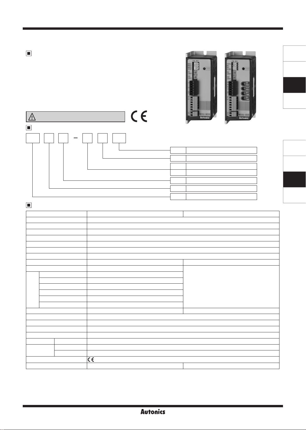
MD2U Series
Compact and High-Performance of 2-Phase Stepper Motor Driver
Features
● Unipolar constant current drive type
● Enable to brake when it stops by STOP current
adjustment
● Low speed and precise control with microstep
(MD2U-MD20)
● Insulate using photocoupler to minimize the inuence
by external noise
● Power supply: 24-35VDC
Please read “Safety Considerations”
in the instruction manual before using.
~~:____
Ordering Information
___
__JI
C €
MD2U-MD20
MD2U-ID20
SENSORS
CONTROLLERS
MOTION DEVICES
SOFTWARE
MD 202 U M D
Item
Drive method
Motor phase
RUN current
Power supply
7
Y~~R========
Step method (resolution)
20 2A/Phase
D 24-35VDC
M Micro Step (20-division)
I Intelligent type
U Unipolar drive
2 2-phase
MD Motor Driver
Specifications
Model MD2U-MD20 MD2U-ID20
Power supply
Allowable voltage range 90 to 110% of the rated voltage
Max. current consumption
RUN current
STOP current 20 to 70% of RUN current (set by STOP current volume)
Drive method Unipolar constant current drive type
Basic step angle 1 8˚/Step
Max. drive speed
Resolution 1, 2, 4, 5, 8, 10, 16, 20-division (1 8˚ to 0.09˚/Step)
Input pulse
Input resistance 300Ω (CW, CCW), 390Ω (HOLD OFF) 3.3kΩ (CW/CCW, RUN/STOP, HOLD OFF)
Insulation resistance Over 200MΩ (at 500VDC megger, between all terminals and case)
Dielectric strength 1000VAC 50/60Hz for 1 min (between all terminals and case)
Noise immunity ±500V the square wave noise (pulse width: 1μs) by the noise simulator
Vibra ion 1 5mm amplitude at frequency of 10 to 55Hz (for 1 min) in each X, Y, Z direction for 2 hours
Shock V
Environment
Approval
Weight
※
1: Since torque characteristics are improved but the driver temperature rises with the 30VDC power supply, the driver should be installed
at the well ventilated environment. Torque is variable by power supply.
※
2: Based on the ambient temperature 25
※
3: RUN current varies depending on the input RUN frequency, and the max. instantaneous RUN current varies also.
※
4: Max. input pulse frequency is max. frequency to be input and is not same as max. pull-out frequency or max. slewing frequency.
※
5: The weight includes packaging. The weight in parenthesis is for unit only.
※
Environment resistance is rated at no freezing or condensa ion.
※
1
※
3
Input pulse width Min. 10μs (CW, CCW), min. 1ms (HOLD OFF)
Duty rate 50% (CW, CCW)
Rising/Falling time Max. 0.5㎲ (CW, CCW)
Pulse input voltage [H]: 4-8VDCᜡ, [L]: 0-0.5VDC
Max. input current 4mA (CW, CCW), 10mA (HOLD OFF)
characteristic
Max. input pulse freq.
ibration 300m/s² (approx. 30G) in each X, Y, Z direction for 3 times
Ambient temp. 0 to 50℃, storage: -10 to 60
Ambient humi. 35 to 85%RH, storage: 35 to 85%RH
※
5
24-35VDC
※
2
3A
0 5-2A/Phase
-
※
4
Max. 50kHz (CW, CCW)
ᜡ
ᜡ
℃
CE:
Approx. 295g (approx. 180g) Approx. 303g (approx. 190g)
, ambient humidity 55%RH.
℃
I
1500rpm
-
I
Autonics
AA-25
(Y)
Closed Loop
Stepper System
(Z)
Stepper Motors
(AA)
Drivers
(AB)
Motion
Controllers
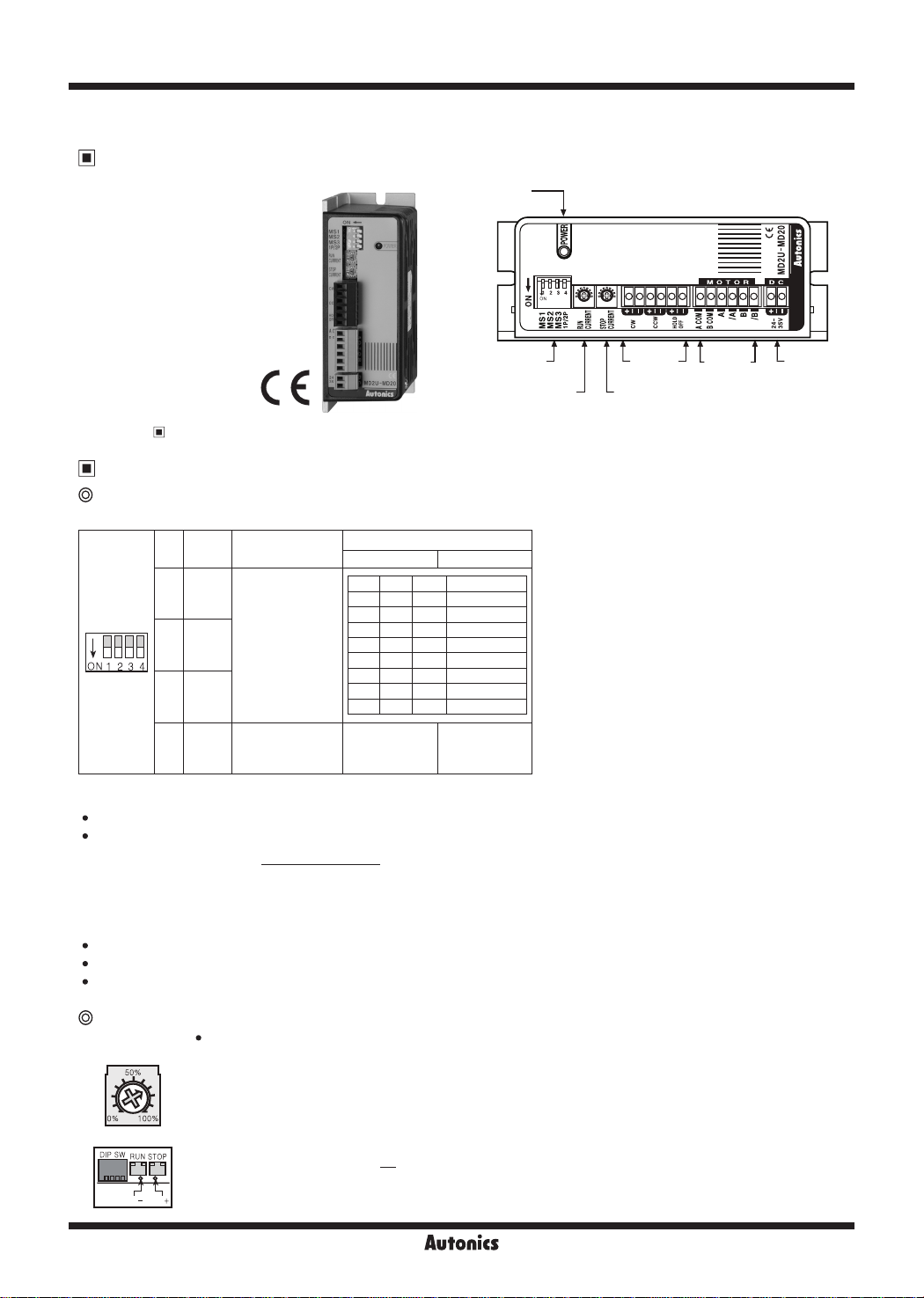
MD2U Series
2-Phase Micro Stepper Driver [MD2U-MD20]
Unit Descriptions
Power indicator
※
Refer to '
selection DIP switch
Function
RUN current volume
Secifications'.
Input
terminal
STOP current volume
Functions
Function selection DIP switch
● Microstep, pulse input method setting
No. Name Function
1 MS1
2 MS2
Microstep setting
IJN~~~~I
3 MS3
4 1P/2P Pulse input method
● Resolution setting (MS1/MS2/MS3)
Select the step angle (motor rotation angle per 1 pulse).
•
The set step angle is dividing basic step angle(1.8°) of 2-phase stepping motor by set resolution value.
•
E.g.) Set step angle =
Resolution
※
Change resolution setting value only when the motor stops.
Basic angle (1.8°)
Switch position
ON OFF
MS1 MS2 MS3 Resolution
ON ON ON 1 (Full-step)
ON ON OFF 2-division
ON OFF ON 4-division
ON OFF OFF 5-division
OFF ON ON 8-division
OFF ON OFF 10-division
OFF OFF ON 16-division
OFF OFF OFF 20-division
1-pulse input
method
2-pulse input
method
Motor
connection
terminal
Power
terminal
● 1P/2P
The switch is to select pulse input method.
•
1-pulse input method:
•
2-pulse input method: CW → CW rotation signal input, CCW → CCW rotation signal input.
•
CW → operating rotation signal input, CCW → rotation direction signal input ([H]: CW, [L]: CCW)
Setting RUN current
RUN current setting is for the current provided to the motor in running status.
RUN
CURRENT
I 50%
~
0% 100%
CT CT
- +
AA-26
•
※
When RUN current is increased, RUN torque of the motor is also increased.
※
When RUN current is set too high, the heat of the motor is increased.
※
Set RUN current properly for the load within the rated current range of the motor.
※
RUN current setting range: 0.5 to 2.0A
※
2.0A0.5A
RUN current setting method: Measure the voltage by connecting a DC voltage meter to both CT+ and
CT- terminals while the motor is running (max. 150rpm)
E.g.) Input voltage (3V) ×
3
※
Change RUN current only when the motor stops.
2
= 2A (motor excitation current)
Autonics
2-Phase Unipolar Stepper Motor Driver
Setting STOP current
STOP
CURRENT
20% 70%
HOLD OFF function
This signal is for rotating axis of the motor with external force or manual positioning.
•
When hold off signal maintains over 1ms as [H], motor excitation is released.
•
When hold off signal maintains over 1ms as [L], motor excitation is in a normal status.
•
※
Use this function only when the motor stops.
※
Refer to '
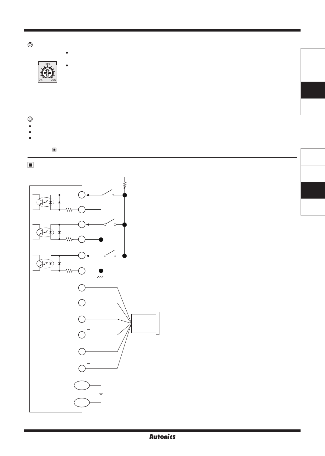
I/O Circuit and Connections
STOP current setting is for the current provided to the motor in stopped status, preventing severe heat
•
of the motor.
This function is for reducing the heat by variable resistance ratio setting within 0 to 100% of RUN
•
current setting range (actual setting range: 20 to 70%).
E.g.) In case of RUN current setting value is 2A and
STOP current setting value is 0% (actual setting range: 20%),
STOP current 2A × 0.2 = 0.4A
※
When STOP current is decreased, STOP torque of the motor is also decreased.
※
When STOP current is set low, the heat of the motor is also low.
※
Change STOP current only when the motor stops.
I/O Circuit and Connections'.
※
+5VDC
1: If the power for driving pulse from external is over than
+5VDC, please connect resistor at the outside.
[Signal]
300Ω
※
1
1
2
CW
(input power max. 24VDC, input current 10-20mA)
※
CW
2-pulse input method (CW rotation signal input)
1-pulse input method (operating rotation signal input)
300Ω
3
4
CCW
※
CCW
2-pulse input method (CCW rotation signal input)
1-pulse input method (rotation direction signal input)
→[H]: CW, [L]: CCW
SENSORS
CONTROLLERS
MOTION DEVICES
SOFTWARE
(Y)
Closed Loop
Stepper System
(Z)
Stepper Motors
(AA)
Drivers
(AB)
Motion
Controllers
390Ω
[Motor]
[Power]
5
6
A-com (black)
1
B-com (white)
2
A (brown)
3
A (orange)
4
B (red)
5
B (yellow)
6
DC+
DC-
HOLD
OFF
GND
+
24-35VDC
-
Motor
※
HOLD OFF
Control signal for motor excitation OFF
→ [H]: Motor excitation OFF
Autonics
AA-27

MD2U Series
Time Chart
● 1 pulse input method
[H]
CW
[L]
[H]
CCW
[L]
'
'
'
' '
'
'
Rotation
position
'
CW
CCW
● 2 pulse input method
[H]
CW
[L]
[H]
CCW
[L]
Rotation
position
※
Do not input CW, CCW signals at the same time in 2-pulse input method.
CW
CCW
CW
It may not operate properly if another direction signal is inputted when one of CW or CCW is [H].
Dimensions
86
76.5
4.5
74
38
(unit: mm)
AA-28
100
20
39 5
4.5
94
100
105
Autonics

2-Phase Unipolar Intelligent Stepper Motor Driver
2-Phase Intelligent Stepper Motor Driver [MD2U-ID20]
Unit Descriptions
Power indicator
START speed volume
RUN speed volume
ACC time setting volume
DEC time setting
volume
SENSORS
CONTROLLERS
MOTION DEVICES
SOFTWARE
※
Refer to '▣ Specifications'.
selection DIP switch
Intelligent type stepper motor driver?
MD2U-ID20 is an intelligent type stepper motor driver including all features to control 2-phase stepper motors so that no
controllers are required.
● Realizing AC motor's driving features to stepper motors
● Controlling START speed, RUN speed and ACC/DEC speed
● User-friendly design to realize various functions (front switch and volume)
Function
RUN current volume
Input
terminal
STOP current volume
Motor
connection
terminal
Power
terminal
Functions
Function selection DIP switch
No. Name Function
SYM/
1
NORMAL
2 MS2
1iaaaa1
ON 1 2 3
※
1: D=Don't care
Reboot the driver after changing function selection switch.
※
@
Selection of Symmetry/Asymmetry
※
The function to make the ACC/DEC time of run-speed as asymmetry or symmetry using DIP switch No. 1.
Speed
(rpm)
3 MS3
H/L
4
SPEED
SYM/NORMAL Symmetry Asymmetry
Max. speed
High/Low speed
Asymmetry (normal) of accel/deceleration
Switch position
ON OFF
I
I
MS2 MS3 H/L SPEED
ON ON
ON OFF 1350
OFF ON 1000
OFF OFF 500
1
※
D
D
ON: High speed
1
※
OFF: Low speed 150
Max. speed
(rpm)
1500
(Y)
Closed Loop
Stepper System
(Z)
Stepper Motors
(AA)
Drivers
(AB)
Motion
Controllers
A AD D
V
ACC time and DEC time are repeated as a asymmetrical gure
Speed
(rpm)
A
V
※
It is able to set the gradient (acceleration and deceleration time) as ACC/DEC time.
@
Selection of max. speed (MS2, MS3)
※
The function to select the max. speed of motors.
※
The max. speed of stepper motor is changed by MS2/MS3 and Hi/Low speed.
※
The features of run and vibration are able to change depending on MS2, MS3.
※
Lower the max. speed to run a motor smoothly.
ACC time and DEC ime are repeated as a symmetrical gure
\_/
Symmetry of accel/deceleration
D
\ I
D
\
~-
Time (sec)
A
Time (sec)
Selection of H/L SPEED
※
H/L SPEED mode selection switch
: Accel/deceleration control is not available in Low speed mode since all sections are included in Pull-in range.
※
Low speed mode: It is able to drive a motor up to 150rpm of max. drive speed.
※
High speed mode: It is able to drive a motor up to 1500rpm of max. drive speed.
Autonics
AA-29

MD2U Series
@
Setting RUN current
RUN
CURRENT
50%
:®:
0% 100%
2.0A0 5A
□~~
CT CT
@
Setting STOP current
STOP
CURRENT
50%
~
0% 100%
70%
20%
@
Setting RUN speed
RUN SPEED
50%
®
0% 100%
0% 100%
@
Setting START speed
START SPEED
50%
®
0% 100%
100%
0%
@
Setting ACC time
ACC TIME
50%
®
0% 100%
100%
0%
@
Setting DEC time
DEC TIME
50%
®
0% 100%
100%
0%
※
ACC Time and DEC Time are declined in proportion to the setting value of START speed.
※
The figures above indicate the factory default for each value.
HOLD OFF function
This signal is for rotating axis of the motor with external force or manual positioning.
•
When hold off signal maintains over 1ms as [H], motor excitation is released.
•
When hold off signal maintains over 1ms as [L], motor excitation is in a normal status.
•
※
Use this function only when the motor stops.
※
Refer to '▣ I/O Circuit and Connections'.
AA-30
RUN current setting is for the current provided to the motor in running status.
•
※
When RUN current is increased, RUN torque of the motor is also increased.
※
When RUN current is set too high, the heat of the motor is increased.
※
Set RUN current properly for the load within the rated current range of the motor.
※
RUN current setting range: 0.5 to 2.0A
※
RUN current setting method: Measure the voltage by connecting a DC voltage meter to both CT+ and
CT- terminals while the motor is running (max. 150rpm)
E.g.) Input voltage (3V) ×
3
※
Change RUN current only when the motor stops.
STOP current setting is for the current provided to the motor in stopped status, preventing severe heat
•
of the motor.
This function is for reducing the heat by variable resistance ratio setting within 0 to 100% of RUN
•
current setting range (actual setting range: 20 to 70%).
E.g.) In case of RUN current setting value is 2A and
STOP current setting value is 0%(actual setting range: 20%),
STOP current 2A × 0.2 = 0.4A
※
When STOP current is decreased, STOP torque of the motor is also decreased.
※
When STOP current is set low, the heat of the motor is also low.
※
Change STOP current only when the motor stops.
※
It sets max. RUN speed.
※
Max. RUN speed can be different depending on max. speed setting (MS2, MS3) and driving mode
setting (Hi/Low speed).
※
Since missing step can occur due to max. input pulse frequency of motors, consider motor type and
its RUN current when setting max. RUN speed.
※
Set the value only when the motor stops.
※
It sets START speed.
※
Max. START speed value is same with RUN speed value.
※
Although START speed must be set within max. starting frequency, it is recommended to set up
START speed within 0 to 50% for stable driving.
※
Set the value only when the motor stops.
※
It sets the acceleration time from START speed to max. RUN speed.
※
Operates in AT_1 operation mode when ACC time is under 33.3%, AT_2 operation mode when
ACC time is under 66.6%, and AT_3 operation mode when ACC time is over 66.6%.
※
AT_1 is 0.5 sec when RUN speed=100%, START speed=0%.
※
AT_2 is 1 sec when RUN speed=100%, START speed=0%.
※
AT_3 is 2 sec when RUN speed=100%, START speed=0%.
※
Set the value only when the motor stops.
※
It sets the deceleration time from max. RUN speed to STOP.
※
Operates in DT_1 operation mode when DEC time is under 33.3%, DT_2 operation mode when
DEC time is under 66.6%, and DT_3 operation mode when DEC time is over 66.6%.
※
DT_1 is 0.5 sec when RUN speed=100%, START speed=0%.
※
DT_2 is 1 sec when RUN speed=100%, START speed=0%.
※
DT_3 is 2 sec when RUN speed=100%, START speed=0%.
※
Set the value only when the motor stops.
2
= 2A (motor excitation current)
Autonics

2-Phase Unipolar Intelligent Stepper Motor Driver
Time Chart
High speed mode
RUN/STOP
CW/CCW
Rota ion speed
and direction
(symmetry mode)
※
It accelerates up to RUN speed during ACC time after RUN signal is ON and decelerates during DEC time after it is OFF.
※
It is disable to change the direction during the signal is ON.
※
It takes 0.5sec for deceleration when DEC time is "0%".
Low speed mode
Max. RUN speed is 150rpm and ACC and DEC time are not available.
It is same with High speed to change RUN/STOP and direction.
I/O Circuit and Connections
Inner power (24-35VDC)
RUN speed
ON
OFF
ON
OFF
3.3kΩ
3.3kΩ
3.3kΩ
5VDC (Inner)
Power
----:---_;__
ACC time
---
RUN/STOP
1
CW/CCW
2
HOLD OFF
3
COM
4
5
6
Inner
adjuster
control
A-com (black)
1
B-com (white)
2
A (brown)
3
A (orange)
4
B (red)
5
B (yellow)
6
DC+
DC-
_,
~-_Jn
ACC time
Motor
stop
0-5VDC
External
(same as DEC ime)
:-----.:
' '
T---~
' '
I I
※
RUN/STOP signal input
→ [ON]: RUN, [OFF]: STOP
※
Direction signal input
→ [ON]: CW, [OFF]: CCW
※
HOLD OFF signal iuput
→ [ON]: HOLD OFF, [OFF]: HOLD ON
● Inner adjuster control
(Adjusting RUN speed with front VR)
Make the connection between terminal No.5 and No.6.
RUN speed
● External adjuster control (Adjusting RUN speed
with connecting external variable resistance)
Connect variable resistance 2
adjuster control. If variable resistance is too low, full range
setting might not be possible. Make sure to adjust RUN
speed VR to maximum for external adjuster control.
RUN speed
● External voltage control (Adjusting RUN speed
with external voltage input)
Make sure to adjust RUN speed VR to maximum external
voltage control.
'
'
' '
' '
' ' '
CW CCW
External
※
adjuster
control 2kΩ
(1 to 3kΩ)
+
24-35VDC
-
-31------i.
DEC
time
I~
' ' '
'
'
'
-
+
※
voltage
control
Motor
'
'
:
COM
5VDC (Inner)
Ω
k
COM
5VDC (Inner)
CW
4
5
6
(1 to 3
4
5
6
Ω
k
) for external
3
2
External adjuster
2kΩ (1 to 3kΩ)
1
SENSORS
CONTROLLERS
MOTION DEVICES
SOFTWARE
(Y)
Closed Loop
Stepper System
(Z)
Stepper Motors
(AA)
Drivers
(AB)
Motion
Controllers
※
Inner adjuster is correlated to external adjuster control and
external voltage control. Make sure that inner adjuster
must be set to maximum in order to set maximum RUN
speed using external adjuster and external voltage.
Autonics
RUN speed
COM
4
-
External voltage
0-5VDC
+
5
6
AA-31

MD2U Series
Dimensions
4.5
100
20
39.5
Proper Usage
~
Follow instructions in 'Proper Usage'. Otherwise, it may cause unexpected accidents.
•
24-35VDC power supply should be insulated and limited voltage/current or Class 2, SELV power supply device.
•
Re-supply power after min. 1 sec from disconnected power.
•
When the signal input voltage is exceeded the rated voltage, connect additional resistance at the outside.
•
Set RUN current within the range of motor's rated current depending on the load.
•
When the rated motor current is over, the heat may be increased and motor may be damaged.
If motor stops, switching for STOP current executed by the current down function.
•
When hold off signal is [H] or current down function is off, the switching does not execute.
Use twisted pair (over 0.2mm2) for the signal cable which should be shorter than 2m.
•
The thickness of cable should be same or thicker than the motor cable's when extending the motor cable.
•
Keep the distance between power cable and signal cable more than 10cm.
•
If the TEST switch is ON, the motor operates immediately and it may be dangerous.
•
Do not change any setting switches (function, run/stop current, resolution switches) during the operation or after
•
supplying power.
Failure to follow this instruction may result in malfunction.
Motor vibration and noise can occur in specific frequency period
•
Change motor installation method or attach the damper.
①
Use the unit out of the dedicated frequence range when vibration and noise occurs due to changing motor RUN speed.
②
For using motor, it is recommended to maintenance and inspection regularly.
•
Unwinding bolts and connection parts for the unit installation and load connection
①
Strange sound from ball bearing of the unit
②
Damage and stress of lead cable of the unit
③
Connection error with motor
④
Inconsistency between the axis of motor output and the center, concentric (eccentric, declination) of the load, etc.
⑤
This product does not prepare protection function for a motor.
•
This unit may be used in the following environments.
•
Indoors (in the environment condition rated in 'Specifications')
①
Altitude max. 2,000m
②
Pollution degree 2
③
Installation category II
④
86
76.5
74
4.5
38
94
100
105
(unit: mm)
AA-32
Autonics
 Loading...