

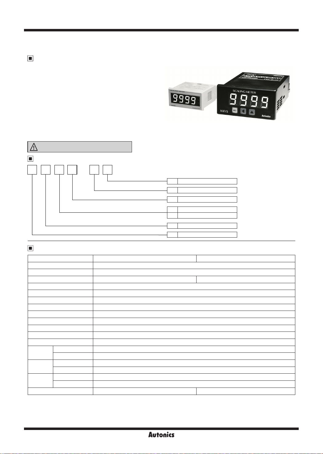
M4NS/M4YS
DIN W48×H24mm, W72×H36mm Loop Powered Digital Scaling Meter
Features
Loop powered type: Power from measured input
●
Measurement input: DC4-20mA
●
Max. display range: -1999 to 9999
●
High/low-limit display scale function
●
Decimal point change function
●
High/low-limit input correction function
●
Display Max./Min. value monitoring function
●
Changeable delay time of monitoring Max./Min. value
●
Display cycle change function
●
(Selectable 0.5 sec/1 sec/2 sec/3 sec/4 sec/5 sec)
Error display function
●
Please read “Safety Considerations”
in the instruction manual before using.
Ordering Information
M 4 N S
Size
Digit
Item
-
N A
9
Ql~L___---------j-------1.___J_
Power supply
LL
Measurement function
Measurement input
A DC4-20mA
l~I
-~
N Loop powered type
~
S Scaling
N DIN W48×H24mm
Y DIN W72×H36mm
4 9999 (4-digit)
M Meter
_____J____J
Specifications
~
Model M4NS-NA M4YS-NA
Power supply Loop powered type
Display method 7-segment LED display (red)
Character height 10mm 14mm
Display accuracy
Display cycle 0.5 sec/1 sec/2 sec/3 sec/4 sec/5 sec
Resolution 12,000 resolution
Max. display range -1999 to 9999
Setting type Setting type with the front keys
Measuring input range
Self-diagnosis function Error display function
Insulation resistance Over 100MΩ (at 500VDC megger)
Dielectric strength 2,000VAC 50/60Hz for 1 min
Vibration
Shock
Environment
Unit weight Approx. 44g Approx. 110g
※
1: Ambient temperature (25℃±5℃): F.S. 0.3% rdg of ±1-digit (-10 to 50℃: F.S. 0.4% rdg ±1-digit)
※
2: Impedance between input lines: Max. 600Ω (based on 24VDC)
Please be aware that activating input power is based on 24VDC, and the recommended impedance also will be lowered if the activating
power is lower.
※
Environment resistance is rated at no freezing or condensation.
※
1
※
2
Mechanical 0.75mm amplitude at frequency of 10 to 55Hz (for 1 min) in each X, Y, Z direction for 1 hour
Malfunction 0.5mm amplitude at frequency of 10 to 55Hz (for 1 min) in each X, Y, Z direction for 10 min
Mechanical 300m/s² (approx. 30G) in each X, Y, Z direction for 3 times
Malfunction 100m/s² (approx. 10G) in each X, Y, Z direction for 3 times
Ambient temperature
Ambient humidity 35 to 85%RH, storage: 35 to 85%RH
F.S. 0.3% rdg ±1-digit
DC4-20mA
-10 to 50℃, storage: -25 to 60℃
I
I
I
O-50
Autonics

Unit Description
1
1. Display value, parameter, error display
2. M,
key
: When enter into parameter group, return to RUN
ll:l!l
mode, after completing parameter setting
Loop Powered Scaling Meter
M4YS-NA M4NS-NA
SCALING
2
3
4
1
3. ▲, key: When enter into the status of parameter setting
~
key
4. ▲,
~
__
g
M4YS
~ a a Autonks
: When enter into the status of parameter setting and
move digit
METER
,_,_,
o•~•~
2 4 3
SENSORS
CONTROLLERS
MOTION DEVICES
SOFTWARE
Dimensions
M4NS-NA
48
SCWJNGMEIBI
11
i 9 9 9
gll
24
-
● Bracket
2323
48.6
45.2
I
p
36.3
~ ~
M4YS-NA
81Cffe.ll.DINIGI
8888
□□□
● Bracket
412
0
llllll!ii"ll!IR!
-
60
(unit: mm)
4
11.6
n
36
9
-
-
48
14.5
=
=
=
=
=
21
● Panel cut-out
Min. 37
7772 6
c=i
c=i
● Panel cut-out
~
Min. 40
;;;;i;i__
Min. 60
30.2
Min. 91
(J)
Temperature
Controllers
(K)
SSRs
(L)
Power
Controllers
(M)
Counters
0
+ 0.3
+ 0.5
22.2
0
31.5
+ 0.5
45
0
+ 0.7
68
0
(N)
Timers
(O)
Digital
Panel Meters
(P)
Indicators
(Q)
Converters
(R)
Digital
Display Units
(S)
Sensor
Controllers
(T)
Switching
Mode Power
Supplies
(U)
Recorders
(V)
HMIs
(W)
Panel PC
(X)
Field Network
Devices
Autonics
O-51

M4NS/M4YS
Parameter 0 Group (Monitoring Mode)
~
Run mode
PEKH
RVN
PEKL
Parameter 1 Group
~
Run mode
l·
l·
DOT
l·
l·
l·
•
I
•
3 sec
BJ
Cllil
BJ
III!!
BJ
III!!
BJ
III!!
BJ
III!!
BJ
~
Low limit scale
L-SC
I
Cllil
High limit scale
H-SC
I
Cllil
Decimal point
I
Cllil
Correcting Low limit value input
INbL
I
Cllil
Correcting High limit value input
INbH
I
Cllil
Max./Min. value monitoring delay time
PEkT
h1
Display cycle
DIsT
~
Display range
ePCT
I I
2)00
r-,
Cllil
I
Cllil
0400
• I
2000
• I
0)00
• I
If
※
Change he Dot position by
0000
• I
!000
• I
00 5
It
Setting range: 00 to 30 sec
I
※
Set the max./min. value monitoring delay time by they
)5 5
I
It
※
Change the display cycle by
• I
3
0)00
0)00$00
Setting range: -1.999 to 9.999, -19.99 to 99.99, -199.9 to 999.9, -1999 to 9999
※
Display value range will vary depending on the decimal point.
I}
※
Move the setting digit by key and change the High limit / Low limit corrected
value by key.
I
)000 0000
M
Setting range: -100 to 100
※
Move the setting digit by key and change the Low limit corrected value by key.
Setting range: 0.900 to 1.100
※
Move the setting digit by
~
01 5
!0 5 @0 5
,
%0 5
~
It
Cllil
I·
Lock
LOC
Cllil
※
Press the key after changing the setting value of the parameter, the setting value is saved and it moves to next parameter.
※
After entering setting parameter, hold the
※
If any key is untouched for 60 sec, it will return to RUN mode.
※
1: Lock
Cllil
OFF
: Enable to change or set Parameter.
ON
: Disable to change or set Parameter but enable to check the setting value in Parameter group.
Disable to enter into the status of change setting value by pressing , keys.
III!!
※
1
※
BJ
※
III!!
HHHH/LLLL
Change
OFF
display value (%) by
BJ.~
Set the Lock in order to disable the parameter setting by
key for 3 sec, it displays
cm
1. Pressing
2. Each Max./Min. value will be shown by pressing key in
monitoring mode and Max./Min. value will be initialized by
pressing key once more.
3. If no key touched for 60 sec, it will return to RUN mode.
4.
When do not use monitoring function, set
PEkT
~
~I
or key.
~
~
1---W·---I
I
BJ
BJ.~
or key.
~
~
=
4 0
~
~
ON
key to enter monitoring mode in RUN mode.
Cllil
~
in parameter setting.
~
I
BJ.~I
00)0
~ ~
key and change the High limit corrected value by key.
~
30 5
I
BJ
key. When pressing the key, it is set as 00 sec.
~
$0 5
2
or key.
~ ~
RUN
and returns to RUN mode
~.~
0
-~~1
~
or key.
~ ~
IBJ.~
#0 5
I
1
00 5
~
for
~
~
O-52
Autonics

Loop Powered Scaling Meter
Parameter
Display Function Setting range
L-SC
Low scale Low limit display value for 4mA input
H-SC
High scale High limit display value for 20mA input
DOT
Decimal point Set Decimal point position
INbL
Input bias low
INbH
Input bias high
PEkT
Max./Min. time
DIsT
Display time Selectable sampling period (sec)
ePCT
Error % Set % of
LOC
Lock Set he lock function ON, OFF
Correct the Low-limit value of display
value (digit)
Correct the High-limit value of display
value (%)
See the Max./Min. value
monitoring delay time (sec)
HHHH/LLLL
display range 0, 1, 2, 3, 4
Connections
NPUT
1 2 3 4 5
+
DC4-20mA
-
-1.999 to 9.999,
-19.99 to 99.99,
-199.9 to 999 9,
-1999 to 9999
0000, 000.0,
00.00, 0 000
-100 to 100
0.900 to 1.100
0 to 30
0.5, 1.0, 2.0, 3.0,
4.0, 5.0
M4YS-NA M4NS-NA
1 2 3 4 5 6 7
DC4-20mA
NPUT
Factory
default
+
0400
2000
0)00
0000
!000
01 5
)5 5
OFF
SENSORS
CONTROLLERS
MOTION DEVICES
SOFTWARE
3
(J)
Temperature
Controllers
(K)
SSRs
(L)
Power
Controllers
(M)
Counters
(N)
Timers
※
Use terminals of size specied below.
a b
a b
<Forked>
1~111
Min.
3 5mm
Min.
7 0mm
Connections of Applications
Temperature
controller
Pressure
Sensor
Converter
+
Output:
DC4-20mA
-
D.P.M
INPUT
(+)
(-)
INPUT
(O)
Digital
Panel Meters
(P)
Indicators
(Q)
Converters
(R)
Digital
Display Units
(S)
Sensor
Controllers
(T)
Switching
Mode Power
Supplies
(U)
Recorders
(V)
HMIs
(W)
Panel PC
(X)
Field Network
Devices
Autonics
O-53

M4NS/M4YS
Functions
Display scale [
L-SC/ H-SC
This function is to display the value setting certain Hi/Low
limit value against DC4-20mA input. For example if set
a=DC4mA, b=DC20mA and A, B as display value, it will be
displayed a=A, b=B.
Input
value
b
b
value
Input
Display
Display
Input
B
value
a
b
A
Input
A
value
b
a
B
INbH/ INbL
Display
B
A
a
Display
a
A
B
Correction [
This function is to adjust the error of display value after
calculating scale value for measuring input and also correct
the input error of sensor etc.
:-100 to 100 [Adjust deviation of low value]
INbL
: 0.900 to 1.100 [Correct gradient (%) of high value]
INbH
E.g.) When display value is 0.0 to 500.0 against 4-20mA
input, if the display value is “1.2” for 4mA input, set -12
(ignore the decimal point) as
“0.0”.It is enable to remove oset of Low display value.
※
When completed above Low value setting then apply
20mA, if the display value is “500.5, the correction value
will be 5005/5000=0.999, set 0.999 as
enable to correct High value is 5005×0.999 = 5000. It is
also ignore the decimal point.
Display Max./Min. value monitoring
[
PEKH / PEKL
This function is to monitor Max. value and Min. value by
current display value then display its Data in
PEkL
and
mode.
Enable to set delay time in
wrong Data by initial over current and set table from 0 to 30
sec and start to monitor after delay time.
]
PEkT
]
Display
B
A
a
Display
a
A
B
value
b
b
Input
value
Input
Display
B
A
Display
A
B
]
value to display
1NbL
1NbH
PEkH
mode to protect the
b
a
Input
value
a
b
Input
value
value then
mode
Error display [
ePCT
]
● Error display
When
①
1) Input current is lower than 3% in 4-20mADC
(16mA scale)
[16mA×3% =0.48mA] → 4mA-0.48mA=3.52mA
2) When it is beyond Min. display value (-1999)
[by display value]
When
②
1) Input current is higher than 3% in 4-20mADC
(16mA scale)
[16mA×3%=0.48mA] → 20mA+0.48mA= 20.48mA.
2) When it is higher than 20.48mA.
When it is beyond Max. display value (9999)
[by display value]
LLLL
HHHH
ashes,
LLLL
ashes,
HHHH
will ash when it is under 3.52mA
ash
● Turn Error display o
and
LLLL
measuring range, therefore it will be disappeared
automatically when input returns to measuring range
are displayed when input is out of
HHHH
● Error setting and sort
It will display the error message according to the setting value
which set % value against analog input range and set it in
ePCT
mode by
Display Description
ePCT 1
ePCT 2
ePCT 3
ePCT 4
ePCT 5
, key.
LLLL/ HHHH
out DC4-20mA range
LLLL/ HHHH
out DC4-20mA range
LLLL/ HHHH
out DC4-20mA range
LLLL/ HHHH
out DC4-20mA range
L SC/ H SC
of DC4-20mA range
are displayed when it is over 0%
are displayed when it is over 1%
are displayed when it is over 2%
are displayed when it is over 3%
are displayed always when it is out
Display cycle delay
It is dicult to display when the measuring input value is
uctuating. In this case it is able to make display value
stable by delaying display cycle.
Display cycle can be changed in
(0.5s/1.0s/2.0s/3.0s/4.0s/5.0s).
If select
%0 S
, it will be the measuring input value on an
average for 5 sec, then display it every 5 sec.
O-54
DIsT
mode of Parameter 2
Autonics
 Loading...