

DRW170800AB
Autonics
DIGITAL PANEL METER
M4M SERIES
I N S T R U C T I O N M A N U A L
-
a..:a
·
Thank you for choosing our Autonics products.
Please read the following safety considerations before use.
Safety Considerations
※
Please observe all safety considerations for safe and proper product operation to avoid
hazards.
※
symbol represents caution due to special circumstances in which hazards may occur.
Failure to follow these instructions may result in serious injury or death.
Warning
Caution
Warning
1. Fail-safe device must be installed when using the unit with machinery that may
cause serious injury or substantial economic loss. (e.g. nuclear power control,
medical equipment, ships, vehicles, railways, aircraft, combustion apparatus,
safety equipment, crime/disaster prevention devices, etc.)
Failure to follow this instruction may result in fire, personal injury, or economic loss.
2. Install on a device panel to use.
Failure to follow this instruction may result in electric shock or fire.
3. Do not connect, repair, or inspect the unit while connected to a power source.
Failure to follow this instruction may result in electric shock or fire.
4. Check 'Connections' before wiring.
Failure to follow this instruction may result in fire.
5. Do not disassemble or modify the unit.
Failure to follow this instruction may result in electric shock or fire.
Caution
1. When connecting the power/measurement input and relay output, use AWG 24
[A=============_=]
(0.20mm2) to AWG 15(1.65mm2) cable and tighten the terminal screw with a
tightening torque of 0.98 to 1.18N.m.
Use proper cables for the rated load current.
Failure to follow this instruc
2. Use the unit within the rated specications.
Failure to follow this instruc ion may result in re or product damage.
3. Use dry cloth to clean the unit, and do not use water or organic solvent.
Failure to follow this instruc ion may result in electric shock or re.
4.
Do not use the unit in the place where ammable/explosive/corrosive gas, humidity,
direct sunlight, radiant heat, vibration, impact, or salinity may be present.
Failure to follow this instruc ion may result in re or explosion.
5. Keep metal chip, dust, and wire residue from owing into the unit.
Failure to follow this instruc ion may result in re or product damage.
Failure to follow these instructions may result in personal injury or
product damage.
ion may result in re or malfunction due to contact failure.
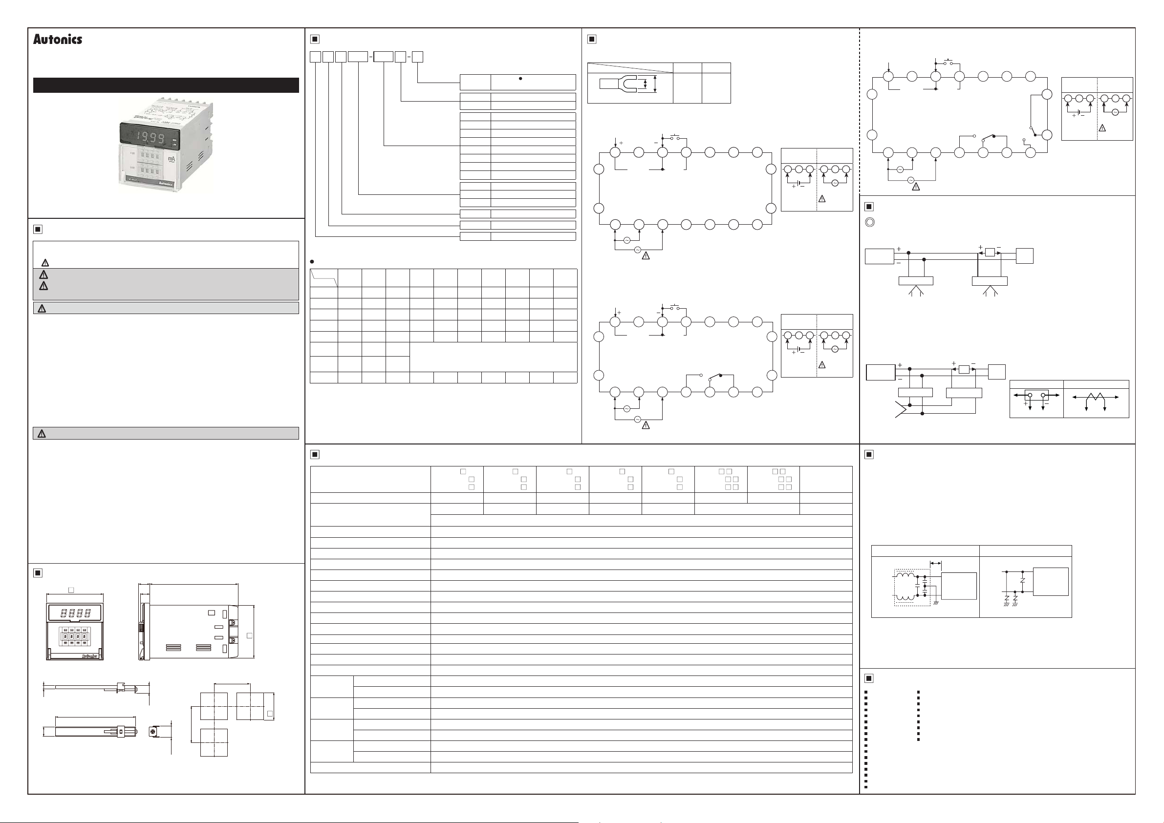
Ordering Information Connections
M
M4 4
l,JUI
※
Jl
Size
Digit
Item
1: 1-5VDC mearsurement input is option.
_J
Output
DV1P
Measurement input range
Input
No-mark
Function
DV
DA
AV(R)
AA(R)
1
※
W
2
※
T(R)
2
※
S(R)
DI 1999
※
1:
Use the transducer. This specification is based on the transducer with 0-10VDC output.
1 2 3 4 5 6 7 8 XX
-
199.9mV 1.999V 19.99V 199.9V 300V
199.9㎂ 1.999mA 19.99mA 199.9mA 1.999A 19.99A 199.9A 1999A
-
-
199.9mV 1.999V 19.99V 199.9V
19.99mA 199.9mA 1.999A 19.99A 199.9A 1999A
-
-
199.9W 1.999kW 19.99kW 199.9kW
-
1999rpm 1999rpm
1999
m/min
- - - - - - - -
When the output of transducer is DC4-20mA or 1-5VDC, please use the scaling meter.
※
2: Use the tacho generator. This specification is based on the tacho generator with
0-10VDC or 0-10VAC output.
※
1999
When "
and then check he cables.
supply
" or "
`999
-
Measurement input /
display scale
AC measuring
method
Measurement function
(input)
1: 0-10VDC
2: 0-10VAC
1999
DX: DC input option
m/min
AX: AC input option
Number
I I
No-mark
R
I I
DV DC voltage
DA
AV AC voltage
AA AC current
W Power
T Rotation (tachometer)
S
DI DC4-20mA (scaling meter)
No-mark Indicator
I
1P
2P Dual set ing
I
j
M DIN W72×H72mm
_j
4 1999 (3½-digit)
j
M Meter
- - -
-
400V
- - - -
" is flashes with a certain measurement input, disconnect power
....
Specications
00
M4M-DV-
Model
M4M1P-DVM4M2P-DV-
Measurement function DC voltage AC voltage DC current AC current Power Rotation Speed Scaling
Max. allowable input
Max. 300VDCᜡMax. 400VACᜠMax. DC 2A Max. AC 5A Max. 10VDCᜡMax. 10VDCᜡ, max. 10VACᜠDC4-20mA
150% for each input specication (at 400VACᜠ: 120%)
Max. display range 1999
Power supply 110/220VACᜠ 50/60Hz (option: 100-240VACᜠ 50/60Hz, 24-70VDCᜡ)
Allowable voltage range 90 to 110% of rated voltage
M4M-AV-
□ □
M4M1P-AV-
□
M4M2P-AV-
□
Power consumption DC input: 2W, AC input: 4VA (in case of the 1P/2P models, DC input: 3W, AC input: 5VA)
Dimensions
00
72
□
14 2
11.7
111. 8
(unit: mm)
Display method 7-segment LED display (red) (character height: 10mm)
Display accuracy DC input: F.S. ±0 2%rdg ±1-digit, AC input: F.S. ±0 5%rdg ±1-digit
Sampling cycle 300ms
A/D conversion method Dual slope intergal method
Response time 2 sec (0 to 1999)
67
□
Sampling times 2.5 times/sec
Output capacity M4M: None / M4M1P: 250VACᜠ 3A, 150VDCᜡ 3A, 1c / M4M2P: 250VACᜠ 3A, 150VDCᜡ 3A, 1c×2
Insulation resistance Over 100MΩ (at 500VDC megger)
Dielectric strength 2000VAC 50/60Hz for 1 minute
● Bracket ● Panel cut-out
Min. 91
4
9.5
101 5
12
14.5
※
The above specications are subject to change and some models may be
Min. 91
I !
+---
--
--1----
'
-
I
discontinued without notice.
※
Be sure to follow cautions written in the instruction manual and the technical
descriptions (catalog, homepage).
0.7
!
□
0
68
Noise immunity ±1kV he square wave noise(pulse width:1㎲) by the noise simulator
Vibration
Shock
Relay
life cycle
Environment
Mechanical 0.75mm amplitude at frequency of 10 to 55Hz in each X, Y, Z direction for 1 hour
Malfunction 0.5mm amplitude at frequency of 10 to 55Hz in each X, Y, Z direction for 10 minutes
Mechanical 300m/s² (approx. 30G) in each X, Y, Z direction for 3 times
Malfunction 100m/s² (approx. 10G) in each X, Y, Z direction for 3 times
Mechanical Min. 10,000,000 times
Electrical Min. 100,000 times (250VAC 3A resistive load)
Ambient temperature -10 to 50℃, storage: -25 to 65
Ambient humidity 35 to 85%RH, storage: 35 to 85%RH
Unit weight M4M: approx. 262g / M4M1P: approx. 290g / M4M2P: approx. 316g
Environment resistance is rated at no freezing or condensation.
※
Refer to "
input range"
Average value (AVG)
Root mean suare value (RMS)
DC current
Speed (speed meter)
J
Single setting
l
Measurement
•
J
I
I
I
Option
Option
- -
- -
□ □ □
□ □ □
℃
Option
Option
Option
Option
M4M-DAM4M1P-DAM4M2P-DA-
※
Use terminals of size specied below.
a
I
b
<Forked>
I
● M4M
9
INPUT
2
LOW
10
HOLD
220VAC
3
HI
8
15 17
1
※
16 18
J
110VAC
0V
1
J
SOURCE
● M4M1P
9
NPUT
2
M4M-WM4M1P-WM4M2P-W-
LOW
10
HOLD
220VAC
3
SOURCE
HI
8
15
16
M4M-AA-
□ □ □
M4M1P-AA-
110VAC
0V
1
M4M2P-AA-
a b
Min.
Max.
3.5mm
7.0mm
12
11
4
12
11
HI
NO NC
4
HI SET OUT
250VAC 3A 1c
150VDC 3A 1c
RESISTIVE LOAD
M4M-T- M4M1P-T -
□
M4M2P-T -
□
14
13
7
6
5
14
13
OUT
COM
5
□□
□□ □□
□□ □□
6
7
M4M-S- M4M1P-S M4M2P-S -
※
Power option
DC SMPS
Power
1 12 23 3
~
SOURCE
24-70VDC 2W
※
Power option
DC Power
Option
1 12 23 3
17
~
SOURCE
24-70VDC 3W
18
M4M-DI
□□
M4M1P-DI
M4M2P-DI
SMPS Power
Option
~
SOURCE
100-240VAC
&
50/60Hz 5VA
SMPS Power
Option
~
SOURCE
100-240VAC
&
50/60Hz 5VA
● M4M2P
HI
8
15 17
16 18
00
(Q)
●
Power of
the load
※
※
※
●
Power of
the load
AC power
※
110VAC
0V
1
Connections of Applications
Simultaneous connection of voltmeter and ammeter
For DC power supply
DC power supply 1
1: Compared to measurement input range, higher measuring voltage needs a multiplier
and lower measuring voltage needs a shunt.
When using voltmeter and ammeter simultaneously, connect the separated power
supply each.
(-) terminal of the power and (-) terminal of measurement input are shorted.
For AC power supply
supply
1: When measuring higher current than measurement input, use a shunt for DC current
and a current transformer (CT) for AC current.
Cautions during Use
00
LOW
9
INPUT
220VAC
2
SOURCE
LOW LOW
HI HI
Voltmeter
LOW LOW
HI HI
Voltmeter
10
HOLD
3
Ammeter
11
HI SET OUT
250VAC 3A 1c
150VDC 3A 1c
RESISTIVE LOAD
NO
4
DC power supply 2
※
1
A
12
OUT
HI
5
Ammeter
13
NC
COM
6
LOW SET OUT
250VAC 3A 1c
150VDC 3A 1c
RESISTIVE LOAD
※
1
A
Load
LOW
NO
Load
Shunt
HI LOW
14
NC
7
OUT
COM
※
Power option
DC Power
Option
1 12 23 3
24-70VDC 3W
Current transformer (CT)
SOURCE
HI LOW
SMPS Power
Option
SOURCE
100-240VAC
50/60Hz 5VA
1. Follow instructions in 'Cautions during Use'.
Otherwise, it may cause unexpected accidents.
2. Install a power switch or circuit breaker in the easily accessible place for
supplying or disconnecting the power.
3. Keep away from high voltage lines or power lines to prevent inductive noise.
In case installing power line and input signal line closely, use line filter or
varistor at power line and shielded wire at input signal line.
Do not use near the equipment which generates strong magnetic force or high
frequency noise.
Connection with the line lter Connection with the varistor
Install the ine flter close
110/
220VAC
~tr-L--
~
Earth ground
H
to he panel meter
HI
Panel meter
LOW
TTi7
110/
220VAC
/II///
HI
Panel meter
LOW
4. This unit may be used in the following environments.
Indoors (in the environment condition rated in 'Specifications')
①
Altitude max. 2,000m
②
Pollution degree 2
③
Installation category II
④
Major products
00
Photoelectric Sensors Temperature Controllers
■
Fiber Optic Sensors Temperature/Humidity Transducers
■
Door Sensors
■
Door Side Sensors Counters
■
Area Sensors
■
Proximity Sensors Panel Meters
■
Pressure Sensors Tachometer/Pulse (Rate) Meters
■
Rotary Encoders Display Units
■
Connector/Sockets Sensor Controllers
■
Switching Mode Power Supplies
■
Control Switches/Lamps/Buzzers
■
I/O Terminal Blocks & Cables
■
Stepper Motors/Drivers/Motion Controllers
■
Graphic/Logic Panels
■
Field Network Devices
■
Laser Marking System (Fiber, Co₂, Nd: YAG)
■
Laser Welding/Cutting System
■
■
■
SSRs/Power Controllers
■
■
Timers
■
■
■
■
■
DRW170800AB
 Loading...