

Page 1
Autodesk® Mechanical Desktop
®
User’s Guide
6
20507-010000-5020A May 3, 2001
Page 2

Copyright © 2001 Autodesk, Inc.
This publication, or parts thereof, may not be reproduced in any form, by any method, for any purpose.
AUTODESK, INC. MAKES NO WARRANTY, EITHER EXPRESSED OR IMPLIED, INCLUDING BUT NOT LIMITED TO ANY IMPLIED
WARRANTIES OF MERCHANTABILITY OR FITNESS FOR A PARTICULAR PURPOSE, REGARDING THESE MATERIALS AND MAKES
SUCH MATERIALS AVAILABLE SOLELY ON AN “AS-IS” BASIS.
IN NO EVENT SHALL AUTODESK, INC. BE LIABLE TO ANYONE FOR SPECIAL, COLLATERAL, INCIDENTAL, OR CONSEQUENTIAL
DAMAGES IN CONNECTION WITH OR ARISING OUT OF PURCHASE OR USE OF THESE MATERIALS. THE SOLE AND EXCLUSIVE
LIABILITY TO AUTODESK, INC., REGARDLESS OF THE FORM OF ACTION, SHALL NOT EXCEED THE PURCHASE PRICE OF THE
MATERIALS DESCRIBED HEREIN.
Autodesk, Inc. reserves the right to revise and improve its products as it sees fit. This publication describes the state of this product at the time of its publication,
and may not reflect the product at all times in the future.
The following are registered trademarks of Autodesk, Inc., in the USA and/or other countries: 3D Plan, 3D Props, 3D Studio, 3D Studio MAX, 3D
Studio VIZ, 3DSurfer, ActiveShapes, ActiveShapes (logo), Actrix, ADE, ADI, Advanced Modeling Extension, AEC Authority (logo), AEC-X, AME,
Animator Pro, Animator Studio, ATC, AUGI, AutoCAD, AutoCAD Data Extension, AutoCAD Development System, AutoCAD LT, AutoCAD Map,
Autodesk, Autodesk Animator, Autodesk (logo), Autodesk MapGuide, Autodesk University, Autodesk View, Autodesk WalkThrough, Autodesk World,
AutoLISP, AutoShade, AutoSketch, AutoSurf, AutoVision, Biped, bringing information down to earth, CAD Overlay, Character Studio, Design
Companion, Design Your World, Design Your World (logo), Drafix, Education by Design, Generic, Generic 3D Drafting, Generic CADD, Generic
Software, Geodyssey, Heidi, HOOPS, Hyperwire, Inside Track, Kinetix, MaterialSpec, Mechanical Desktop, Multimedia Explorer, NAAUG, ObjectARX,
Office Series, Opus, PeopleTracker, Physique, Planix, Powered with Autodesk Technology, Powered with Autodesk Technology (logo), RadioRay,
Rastation, Softdesk, Softdesk (logo), Solution 3000, Tech Talk, Texture Universe, The AEC Authority, The Auto Architect, TinkerTech, VISION*, WHIP!,
WHIP! (logo), Woodbourne, WorkCenter, and World-Creating Toolkit.
The following are trademarks of Autodesk, Inc., in the USA and/or other countries: 3D on the PC, 3ds max, ACAD, Advanced User Interface, AEC
Office, AME Link, Animation Partner, Animation Player, Animation Pro Player, A Studio in Every Computer, ATLAST, Auto-Architect, AutoCAD
Architectural Desktop, AutoCAD Architectural Desktop Learning Assistance, AutoCAD Learning Assistance, AutoCAD LT Learning Assistance, AutoCAD
Simulator, AutoCAD SQL Extension, AutoCAD SQL Interface, Autodesk Animator Clips, Autodesk Animator Theatre, Autodesk Device Interface,
Autodesk Inventor, Autodesk PhotoEDIT, Autodesk Software Developer’s Kit, Autodesk Streamline, Autodesk View DwgX, AutoFlix, AutoPAD,
AutoSnap, AutoTrack, Built with ObjectARX (logo), ClearScale, Colour Warper, Combustion, Concept Studio, Content Explorer, cornerStone Toolkit,
Dancing Baby (image), Design 2000 (logo), DesignCenter, Design Doctor, Designer’s Toolkit, DesignProf, DesignServer, DWG Linking, DWG
Unplugged, DXF, Extending the Design Team, FLI, FLIC, GDX Driver, Generic 3D, gmax, Heads-up Design, Home Series, i-drop, Kinetix (logo),
Lightscape, ObjectDBX, onscreen onair online, Ooga-Chaka, Photo Landscape, Photoscape, Plasma, Plugs and Sockets, PolarSnap, Pro Landscape,
QuickCAD, Reactor, Real-Time Roto, Render Queue, SchoolBox, Simply Smarter Diagramming, SketchTools, Sparks, Suddenly Everything Clicks,
Supportdesk, The Dancing Baby, Transform Ideas Into Reality, Visual LISP, Visual Syllabus, VIZable, Volo, and Where Design Connects.
All other brand names, product names or trademarks belong to their respective holders.
ACIS Copyright © 1989-2001 Spatial Corp.
Third Party Software Program Credits
Anderson, et. al. LAPACK Users’ Guide, Third Edition. Society for Industrial and Applied Mathematics, 1999.
Portions Copyright © 1991-1996 Arthur D. Applegate. All rights reserved.
Typefaces from the Bitstream ® typeface library copyright 1992.
Cypress Enable™, Cypress Software, Inc.
dBASE is a registered trademark of Ksoft, Inc.
Portions licensed from D-Cubed Ltd. DCM-2D and CDM are a trademark of D-Cubed Ltd. DCM-2D Copyright D-Cubed Ltd. 1989-2001.
CDM Copyright D-Cubed Ltd. 1998-2001.
SPEC is a registered trademark of Associated Spring/Barnes Group, Inc.
Portions of this software are based on the work of the Independent JPEG Group.
InstallShield™ 3.0. Copyright © 1997 InstallShield Software Corporation. All rights reserved.
Licensing Technology Copyright © C-Dilla Ltd. UK 1996, 1997, 1998, 1999, 2000, 2001.
MD5C.C - RSA Data Security, Inc., MD5 message-digest algorithm Copyright © 1991-1992, RSA Data Security, Inc. Created 1991. All
rights reserved.
International CorrectSpell™ Spelling Correction System © 1995 by Lernout & Hauspie Speech Products, N.V. All rights reserved.
LUCA TCP/IP Package, Portions Copyright © 1997 Langener GmbH. All rights reserved.
Copyright © 1997 Microsoft Corporation. All rights reserved.
Microsoft® HTML Help Copyright © Microsoft Corporation 2001.
Microsoft® Internet Explorer 5 Copyright © Microsoft Corporation 2001. All rights reserved
Microsoft® Windows NetMeeting Copyright © Microsoft Corporation 2001. All rights reserved
Objective Grid ©, Stingray Software a division of Rogue Wave Software, Inc.
Typefaces from Payne Loving Trust © 1996. All rights reserved.
PKWARE Data Compression Library ©, PKWARE, Inc.
SMLib © 1998-2000, IntegrityWare, Inc., GeomWare, Inc., and Solid Modeling Solutions, Inc.
Use, duplication, or disclosure by the U. S. Government is subject to restrictions as set forth in FAR 12.212 (Commercial Computer
Software-Restricted Rights) and DFAR 227.7202 (Rights in Technical Data and Computer Software), as applicable.
All Rights Reserved
Autodesk Trademarks
Third Party Trademarks
GOVERNMENT USE
12345678910
Page 3

Contents
Part I Getting Started with Autodesk® Mechanical Desktop® .1
Chapter 1 Welcome . . . . . . . . . . . . . . . . . . . . . . . . . . . . . . . . . . . . . . . . . . . . . . 3
What is Autodesk Mechanical Desktop?. . . . . . . . . . . . . . . . . . . . . . . . . . . . 4
Making the Transition from AutoCAD . . . . . . . . . . . . . . . . . . . . . . . . . . . . . 5
Migrating Files from Previous Releases . . . . . . . . . . . . . . . . . . . . . . . . . . . . . 5
Data Exchange. . . . . . . . . . . . . . . . . . . . . . . . . . . . . . . . . . . . . . . . . . . . . . . . 6
Chapter 2 Modeling with Autodesk® Mechanical Desktop®. . . . . . . . . . . . . . . 7
Mechanical Desktop Basics . . . . . . . . . . . . . . . . . . . . . . . . . . . . . . . . . . . . . . 8
Chapter 3 The User Interface . . . . . . . . . . . . . . . . . . . . . . . . . . . . . . . . . . . . . 13
Mechanical Desktop Today. . . . . . . . . . . . . . . . . . . . . . . . . . . . . . . . . . . . . 14
Mechanical Desktop Environments . . . . . . . . . . . . . . . . . . . . . . . . . . . . . . 15
Assembly Modeling Environment . . . . . . . . . . . . . . . . . . . . . . . . . . . 15
Part Modeling Environment . . . . . . . . . . . . . . . . . . . . . . . . . . . . . . . 16
Mechanical Desktop Interface. . . . . . . . . . . . . . . . . . . . . . . . . . . . . . . . . . . 17
Desktop Browser. . . . . . . . . . . . . . . . . . . . . . . . . . . . . . . . . . . . . . . . . 18
Issuing Commands . . . . . . . . . . . . . . . . . . . . . . . . . . . . . . . . . . . . . . 24
Chapter 4 Documentation and Support . . . . . . . . . . . . . . . . . . . . . . . . . . . . . 27
Printed and Online Manuals. . . . . . . . . . . . . . . . . . . . . . . . . . . . . . . . . . . . 28
Mechanical Desktop Printed Manual . . . . . . . . . . . . . . . . . . . . . . . . 28
AutoCAD Printed Manual . . . . . . . . . . . . . . . . . . . . . . . . . . . . . . . . . 28
Online Installation Guide . . . . . . . . . . . . . . . . . . . . . . . . . . . . . . . . . 28
AutoCAD 2002 Documentation . . . . . . . . . . . . . . . . . . . . . . . . . . . . 29
iii
Page 4

Mechanical Desktop Help . . . . . . . . . . . . . . . . . . . . . . . . . . . . . . . . . . . . . .30
Updating Help Files. . . . . . . . . . . . . . . . . . . . . . . . . . . . . . . . . . . . . . .30
Product Support Assistance in Help. . . . . . . . . . . . . . . . . . . . . . . . . . . . . . .31
Updating the Support Assistance Knowledge Base. . . . . . . . . . . . . . .31
Learning and Training Resources. . . . . . . . . . . . . . . . . . . . . . . . . . . . . . . . .31
Internet Resources . . . . . . . . . . . . . . . . . . . . . . . . . . . . . . . . . . . . . . . . . . . .32
Part I Autodesk® Mechanical Desktop® Tutorials. . . . . . . . . . 33
Chapter 5 Using the Tutorials . . . . . . . . . . . . . . . . . . . . . . . . . . . . . . . . . . . . . 35
How the Tutorials are Organized . . . . . . . . . . . . . . . . . . . . . . . . . . . . . . . . .36
Accessing Mechanical Desktop Commands. . . . . . . . . . . . . . . . . . . . . . . . .37
Positioning the Desktop Browser . . . . . . . . . . . . . . . . . . . . . . . . . . . . . . . . .38
Backing up Tutorial Drawing Files . . . . . . . . . . . . . . . . . . . . . . . . . . . . . . . .40
Chapter 6 Creating Parametric Sketches. . . . . . . . . . . . . . . . . . . . . . . . . . . . . 41
Key Terms . . . . . . . . . . . . . . . . . . . . . . . . . . . . . . . . . . . . . . . . . . . . . . . . . . .42
Basic Concepts of Parametric Sketching . . . . . . . . . . . . . . . . . . . . . . . . . . .43
Sketching Tips . . . . . . . . . . . . . . . . . . . . . . . . . . . . . . . . . . . . . . . . . . . . . . .44
Creating Profile Sketches . . . . . . . . . . . . . . . . . . . . . . . . . . . . . . . . . . . . . . .45
Creating Text Sketch Profiles . . . . . . . . . . . . . . . . . . . . . . . . . . . . . . .45
Creating Open Profile Sketches . . . . . . . . . . . . . . . . . . . . . . . . . . . . .46
Creating Closed Profile Sketches . . . . . . . . . . . . . . . . . . . . . . . . . . . .46
Using Default Sketch Rules . . . . . . . . . . . . . . . . . . . . . . . . . . . . . . . . .47
Using Custom Sketch Rules . . . . . . . . . . . . . . . . . . . . . . . . . . . . . . . .51
Using Nested Loops. . . . . . . . . . . . . . . . . . . . . . . . . . . . . . . . . . . . . . .56
Creating Path Sketches. . . . . . . . . . . . . . . . . . . . . . . . . . . . . . . . . . . . . . . . .58
Creating 2D Path Sketches . . . . . . . . . . . . . . . . . . . . . . . . . . . . . . . . .58
Creating 3D Path Sketches . . . . . . . . . . . . . . . . . . . . . . . . . . . . . . . . .62
Creating Cut Line Sketches . . . . . . . . . . . . . . . . . . . . . . . . . . . . . . . . . . . . .72
Creating Split Line Sketches. . . . . . . . . . . . . . . . . . . . . . . . . . . . . . . . . . . . .77
Creating Break Line Sketches . . . . . . . . . . . . . . . . . . . . . . . . . . . . . . . . . . . .80
Chapter 7 Constraining Sketches . . . . . . . . . . . . . . . . . . . . . . . . . . . . . . . . . . 83
Key Terms . . . . . . . . . . . . . . . . . . . . . . . . . . . . . . . . . . . . . . . . . . . . . . . . . . .84
Basic Concepts of Creating Constraints. . . . . . . . . . . . . . . . . . . . . . . . . . . .85
Constraining Tips. . . . . . . . . . . . . . . . . . . . . . . . . . . . . . . . . . . . . . . . . . . . .86
Constraining Sketches . . . . . . . . . . . . . . . . . . . . . . . . . . . . . . . . . . . . . . . . .86
iv | Contents
Page 5

Applying Geometric Constraints . . . . . . . . . . . . . . . . . . . . . . . . . . . . . . . . 88
Showing Constraint Symbols. . . . . . . . . . . . . . . . . . . . . . . . . . . . . . . 90
Replacing Constraints . . . . . . . . . . . . . . . . . . . . . . . . . . . . . . . . . . . . 91
Applying Dimension Constraints . . . . . . . . . . . . . . . . . . . . . . . . . . . . . . . . 94
Creating Profile Sketches . . . . . . . . . . . . . . . . . . . . . . . . . . . . . . . . . . 96
Adding Dimensions . . . . . . . . . . . . . . . . . . . . . . . . . . . . . . . . . . . . . . 97
Appending Sketches. . . . . . . . . . . . . . . . . . . . . . . . . . . . . . . . . . . . . 100
Modifying Dimensions . . . . . . . . . . . . . . . . . . . . . . . . . . . . . . . . . . 104
Using Construction Geometry . . . . . . . . . . . . . . . . . . . . . . . . . . . . . . . . . 105
Creating Profile Sketches . . . . . . . . . . . . . . . . . . . . . . . . . . . . . . . . . 105
Adding Project Constraints . . . . . . . . . . . . . . . . . . . . . . . . . . . . . . . 107
Adding Parametric Dimensions . . . . . . . . . . . . . . . . . . . . . . . . . . . . 109
Constraining Path Sketches . . . . . . . . . . . . . . . . . . . . . . . . . . . . . . . 111
Controlling Tangency . . . . . . . . . . . . . . . . . . . . . . . . . . . . . . . . . . . 115
Chapter 8 Creating Sketched Features . . . . . . . . . . . . . . . . . . . . . . . . . . . . . 121
Key Terms . . . . . . . . . . . . . . . . . . . . . . . . . . . . . . . . . . . . . . . . . . . . . . . . . 122
Basic Concepts of Sketched Features. . . . . . . . . . . . . . . . . . . . . . . . . . . . . 123
Creating Extruded Features . . . . . . . . . . . . . . . . . . . . . . . . . . . . . . . . . . . . 124
Extruding Closed Profiles. . . . . . . . . . . . . . . . . . . . . . . . . . . . . . . . . 124
Editing Extruded Features . . . . . . . . . . . . . . . . . . . . . . . . . . . . . . . . . . . . . 130
Extruding Open Profiles. . . . . . . . . . . . . . . . . . . . . . . . . . . . . . . . . . 133
Creating Rib Features . . . . . . . . . . . . . . . . . . . . . . . . . . . . . . . . . . . . 133
Creating Thin Features. . . . . . . . . . . . . . . . . . . . . . . . . . . . . . . . . . . 136
Creating Emboss Features . . . . . . . . . . . . . . . . . . . . . . . . . . . . . . . . 140
Editing Emboss Features. . . . . . . . . . . . . . . . . . . . . . . . . . . . . . . . . . 143
Creating Loft Features . . . . . . . . . . . . . . . . . . . . . . . . . . . . . . . . . . . . . . . . 143
Creating Linear Lofts . . . . . . . . . . . . . . . . . . . . . . . . . . . . . . . . . . . . 143
Creating Cubic Lofts . . . . . . . . . . . . . . . . . . . . . . . . . . . . . . . . . . . . 145
Editing Loft Features . . . . . . . . . . . . . . . . . . . . . . . . . . . . . . . . . . . . . . . . . 149
Creating Revolved Features . . . . . . . . . . . . . . . . . . . . . . . . . . . . . . . . . . . . 150
Editing Revolved Features . . . . . . . . . . . . . . . . . . . . . . . . . . . . . . . . . . . . . 151
Creating Face Splits . . . . . . . . . . . . . . . . . . . . . . . . . . . . . . . . . . . . . . . . . . 152
Editing Face Splits . . . . . . . . . . . . . . . . . . . . . . . . . . . . . . . . . . . . . . . . . . . 155
Creating Sweep Features . . . . . . . . . . . . . . . . . . . . . . . . . . . . . . . . . . . . . . 155
Creating 2D Sweep Features. . . . . . . . . . . . . . . . . . . . . . . . . . . . . . . 156
Creating 3D Sweep Features. . . . . . . . . . . . . . . . . . . . . . . . . . . . . . . 157
Editing Sweep Features . . . . . . . . . . . . . . . . . . . . . . . . . . . . . . . . . . . . . . . 163
Creating Bend Features . . . . . . . . . . . . . . . . . . . . . . . . . . . . . . . . . . . . . . . 163
Editing Bend Features . . . . . . . . . . . . . . . . . . . . . . . . . . . . . . . . . . . . . . . . 165
Contents | v
Page 6

Chapter 9 Creating Work Features . . . . . . . . . . . . . . . . . . . . . . . . . . . . . . . . 167
Key Terms . . . . . . . . . . . . . . . . . . . . . . . . . . . . . . . . . . . . . . . . . . . . . . . . . .168
Basic Concepts of Work Features . . . . . . . . . . . . . . . . . . . . . . . . . . . . . . . .169
Creating Work Planes. . . . . . . . . . . . . . . . . . . . . . . . . . . . . . . . . . . . . . . . .170
Editing Work Planes. . . . . . . . . . . . . . . . . . . . . . . . . . . . . . . . . . . . . . . . . .173
Creating Work Axes . . . . . . . . . . . . . . . . . . . . . . . . . . . . . . . . . . . . . . . . . .174
Editing Work Axes . . . . . . . . . . . . . . . . . . . . . . . . . . . . . . . . . . . . . . . . . . .177
Creating Work Points. . . . . . . . . . . . . . . . . . . . . . . . . . . . . . . . . . . . . . . . .179
Editing Work Points . . . . . . . . . . . . . . . . . . . . . . . . . . . . . . . . . . . . . . . . . .182
Chapter 10 Creating Placed Features . . . . . . . . . . . . . . . . . . . . . . . . . . . . . . . 185
Key Terms . . . . . . . . . . . . . . . . . . . . . . . . . . . . . . . . . . . . . . . . . . . . . . . . . .186
Basic Concepts of Placed Features . . . . . . . . . . . . . . . . . . . . . . . . . . . . . . .187
Creating Hole Features . . . . . . . . . . . . . . . . . . . . . . . . . . . . . . . . . . . . . . . .188
Creating Thread Features . . . . . . . . . . . . . . . . . . . . . . . . . . . . . . . . . . . . . .190
Editing Hole Features . . . . . . . . . . . . . . . . . . . . . . . . . . . . . . . . . . . . . . . . .192
Editing Thread Features . . . . . . . . . . . . . . . . . . . . . . . . . . . . . . . . . . . . . . .193
Creating Face Drafts . . . . . . . . . . . . . . . . . . . . . . . . . . . . . . . . . . . . . . . . . .194
Editing Face Drafts . . . . . . . . . . . . . . . . . . . . . . . . . . . . . . . . . . . . . . . . . . .198
Creating Fillet Features. . . . . . . . . . . . . . . . . . . . . . . . . . . . . . . . . . . . . . . .199
Editing Fillet Features. . . . . . . . . . . . . . . . . . . . . . . . . . . . . . . . . . . . . . . . .202
Creating Chamfer Features. . . . . . . . . . . . . . . . . . . . . . . . . . . . . . . . . . . . .204
Editing Chamfer Features. . . . . . . . . . . . . . . . . . . . . . . . . . . . . . . . . . . . . .208
Creating Shell Features. . . . . . . . . . . . . . . . . . . . . . . . . . . . . . . . . . . . . . . .209
Editing Shell Features . . . . . . . . . . . . . . . . . . . . . . . . . . . . . . . . . . . . . . . . .210
Creating Surface Cut Features . . . . . . . . . . . . . . . . . . . . . . . . . . . . . . . . . .212
Editing Surface Cut Features . . . . . . . . . . . . . . . . . . . . . . . . . . . . . . . . . . .213
Creating Pattern Features . . . . . . . . . . . . . . . . . . . . . . . . . . . . . . . . . . . . . .214
Editing Pattern Features . . . . . . . . . . . . . . . . . . . . . . . . . . . . . . . . . . . . . . .223
Editing Array Features . . . . . . . . . . . . . . . . . . . . . . . . . . . . . . . . . . . . . . . .223
Creating Copied Features . . . . . . . . . . . . . . . . . . . . . . . . . . . . . . . . . . . . . .224
Editing Copied Features . . . . . . . . . . . . . . . . . . . . . . . . . . . . . . . . . . . . . . .227
Creating Combined Features . . . . . . . . . . . . . . . . . . . . . . . . . . . . . . . . . . .227
Editing Combined Features . . . . . . . . . . . . . . . . . . . . . . . . . . . . . . . . . . . .228
Creating Part Splits. . . . . . . . . . . . . . . . . . . . . . . . . . . . . . . . . . . . . . . . . . .229
Editing Part Splits . . . . . . . . . . . . . . . . . . . . . . . . . . . . . . . . . . . . . . . . . . . .231
Chapter 11 Using Design Variables . . . . . . . . . . . . . . . . . . . . . . . . . . . . . . . . . 233
Key Terms . . . . . . . . . . . . . . . . . . . . . . . . . . . . . . . . . . . . . . . . . . . . . . . . . .234
Basic Concepts of Design Variables . . . . . . . . . . . . . . . . . . . . . . . . . . . . . .235
Preparing The Drawing File . . . . . . . . . . . . . . . . . . . . . . . . . . . . . . . . . . . .236
vi | Contents
Page 7

Using Design Variables . . . . . . . . . . . . . . . . . . . . . . . . . . . . . . . . . . . . . . . 239
Active Part Design Variables . . . . . . . . . . . . . . . . . . . . . . . . . . . . . . 239
Global Design Variables. . . . . . . . . . . . . . . . . . . . . . . . . . . . . . . . . . 239
Creating Active Part Design Variables. . . . . . . . . . . . . . . . . . . . . . . . . . . . 239
Assigning Design Variables to Active Parts . . . . . . . . . . . . . . . . . . . . . . . . 242
Modifying Design Variables . . . . . . . . . . . . . . . . . . . . . . . . . . . . . . . . . . . 244
Working with Global Design Variables. . . . . . . . . . . . . . . . . . . . . . . . . . . 246
Chapter 12 Creating Parts . . . . . . . . . . . . . . . . . . . . . . . . . . . . . . . . . . . . . . . . 253
Key Terms . . . . . . . . . . . . . . . . . . . . . . . . . . . . . . . . . . . . . . . . . . . . . . . . . 254
Basic Concepts of Creating Parts. . . . . . . . . . . . . . . . . . . . . . . . . . . . . . . . 255
Creating Base Features. . . . . . . . . . . . . . . . . . . . . . . . . . . . . . . . . . . . . . . . 257
Sketching Base Features . . . . . . . . . . . . . . . . . . . . . . . . . . . . . . . . . . 258
Creating Work Features . . . . . . . . . . . . . . . . . . . . . . . . . . . . . . . . . . 264
Defining Sketch Planes . . . . . . . . . . . . . . . . . . . . . . . . . . . . . . . . . . 267
Creating Extruded Features . . . . . . . . . . . . . . . . . . . . . . . . . . . . . . . . . . . . 270
Constraining Sketches . . . . . . . . . . . . . . . . . . . . . . . . . . . . . . . . . . . 271
Dimensioning Sketches . . . . . . . . . . . . . . . . . . . . . . . . . . . . . . . . . . 274
Creating Constraints Between Features. . . . . . . . . . . . . . . . . . . . . . 276
Editing Sketches . . . . . . . . . . . . . . . . . . . . . . . . . . . . . . . . . . . . . . . . 280
Extruding Profiles. . . . . . . . . . . . . . . . . . . . . . . . . . . . . . . . . . . . . . . 282
Creating Revolved Features . . . . . . . . . . . . . . . . . . . . . . . . . . . . . . . . . . . . 284
Creating Symmetrical Features . . . . . . . . . . . . . . . . . . . . . . . . . . . . . . . . . 290
Constraining Sketches . . . . . . . . . . . . . . . . . . . . . . . . . . . . . . . . . . . 291
Refining Parts . . . . . . . . . . . . . . . . . . . . . . . . . . . . . . . . . . . . . . . . . . . . . . 297
Shading and Lighting Models . . . . . . . . . . . . . . . . . . . . . . . . . . . . . . . . . . 304
Chapter 13 Creating Drawing Views. . . . . . . . . . . . . . . . . . . . . . . . . . . . . . . . 307
Key Terms . . . . . . . . . . . . . . . . . . . . . . . . . . . . . . . . . . . . . . . . . . . . . . . . . 308
Basic Concepts of Creating Drawing Views . . . . . . . . . . . . . . . . . . . . . . . 309
Planning and Setting Up Drawings. . . . . . . . . . . . . . . . . . . . . . . . . . . . . . 309
Creating Drawing Views . . . . . . . . . . . . . . . . . . . . . . . . . . . . . . . . . . . . . . 310
Cleaning Up Drawings . . . . . . . . . . . . . . . . . . . . . . . . . . . . . . . . . . . . . . . 322
Hiding Extraneous Dimensions . . . . . . . . . . . . . . . . . . . . . . . . . . . . 322
Moving Dimensions. . . . . . . . . . . . . . . . . . . . . . . . . . . . . . . . . . . . . 325
Hiding Extraneous Lines . . . . . . . . . . . . . . . . . . . . . . . . . . . . . . . . . 328
Enhancing Drawings . . . . . . . . . . . . . . . . . . . . . . . . . . . . . . . . . . . . . . . . . 330
Changing Dimension Attributes . . . . . . . . . . . . . . . . . . . . . . . . . . . 330
Creating Reference Dimensions. . . . . . . . . . . . . . . . . . . . . . . . . . . . 332
Creating Hole Notes. . . . . . . . . . . . . . . . . . . . . . . . . . . . . . . . . . . . . 333
Creating Centerlines . . . . . . . . . . . . . . . . . . . . . . . . . . . . . . . . . . . . 336
Creating Other Annotation Items . . . . . . . . . . . . . . . . . . . . . . . . . . 337
Modifying Drawing Views . . . . . . . . . . . . . . . . . . . . . . . . . . . . . . . . 340
Exporting Drawing Views . . . . . . . . . . . . . . . . . . . . . . . . . . . . . . . . . . . . . 343
Contents | vii
Page 8

Chapter 14 Creating Shells . . . . . . . . . . . . . . . . . . . . . . . . . . . . . . . . . . . . . . . 345
Key Terms . . . . . . . . . . . . . . . . . . . . . . . . . . . . . . . . . . . . . . . . . . . . . . . . . .346
Basic Concepts of Creating Shells . . . . . . . . . . . . . . . . . . . . . . . . . . . . . . .347
Adding Shell Features to Models . . . . . . . . . . . . . . . . . . . . . . . . . . . . . . . .347
Using Replay to Examine Designs . . . . . . . . . . . . . . . . . . . . . . . . . .348
Cutting Models to Create Shells . . . . . . . . . . . . . . . . . . . . . . . . . . . .350
Editing Shell Features . . . . . . . . . . . . . . . . . . . . . . . . . . . . . . . . . . . .352
Adding Multiple Wall Thicknesses . . . . . . . . . . . . . . . . . . . . . . . . . .354
Managing Multiple Thickness Overrides . . . . . . . . . . . . . . . . . . . . .358
Chapter 15 Creating Table Driven Parts . . . . . . . . . . . . . . . . . . . . . . . . . . . . . 361
Key Terms . . . . . . . . . . . . . . . . . . . . . . . . . . . . . . . . . . . . . . . . . . . . . . . . . .362
Basic Concepts of Table Driven Parts. . . . . . . . . . . . . . . . . . . . . . . . . . . . .363
Setting Up Tables . . . . . . . . . . . . . . . . . . . . . . . . . . . . . . . . . . . . . . . . . . . .364
Displaying Part Versions . . . . . . . . . . . . . . . . . . . . . . . . . . . . . . . . . . . . . .366
Editing Tables . . . . . . . . . . . . . . . . . . . . . . . . . . . . . . . . . . . . . . . . . . . . . . .367
Resolving Common Table Errors . . . . . . . . . . . . . . . . . . . . . . . . . . . . . . . .369
Suppressing Features. . . . . . . . . . . . . . . . . . . . . . . . . . . . . . . . . . . . . . . . . .371
Working with Two Part Versions . . . . . . . . . . . . . . . . . . . . . . . . . . . . . . . .377
Creating Drawing Views. . . . . . . . . . . . . . . . . . . . . . . . . . . . . . . . . . . . . . .379
Cleaning Up the Drawing . . . . . . . . . . . . . . . . . . . . . . . . . . . . . . . . . . . . .384
Displaying Dimensions as Parameters . . . . . . . . . . . . . . . . . . . . . . .384
Hiding Extraneous Dimensions . . . . . . . . . . . . . . . . . . . . . . . . . . . .385
Moving Dimensions . . . . . . . . . . . . . . . . . . . . . . . . . . . . . . . . . . . . .387
Enhancing Drawings . . . . . . . . . . . . . . . . . . . . . . . . . . . . . . . . . . . . . . . . .390
Creating Power Dimensions . . . . . . . . . . . . . . . . . . . . . . . . . . . . . . .390
Creating Hole Notes . . . . . . . . . . . . . . . . . . . . . . . . . . . . . . . . . . . . .393
Pasting Linked Spreadsheets . . . . . . . . . . . . . . . . . . . . . . . . . . . . . . . . . . .396
Chapter 16 Assembling Parts. . . . . . . . . . . . . . . . . . . . . . . . . . . . . . . . . . . . . . 399
Key Terms . . . . . . . . . . . . . . . . . . . . . . . . . . . . . . . . . . . . . . . . . . . . . . . . . .400
Basic Concepts of Assembling Parts. . . . . . . . . . . . . . . . . . . . . . . . . . . . . .401
Starting Assembly Designs . . . . . . . . . . . . . . . . . . . . . . . . . . . . . . . . . . . . .402
Using External Parts in Assemblies . . . . . . . . . . . . . . . . . . . . . . . . . . . . . .403
Assembling Parts. . . . . . . . . . . . . . . . . . . . . . . . . . . . . . . . . . . . . . . . . . . . .406
Constraining Parts . . . . . . . . . . . . . . . . . . . . . . . . . . . . . . . . . . . . . .407
Using the Desktop Browser. . . . . . . . . . . . . . . . . . . . . . . . . . . . . . . .414
Getting Information from Assemblies . . . . . . . . . . . . . . . . . . . . . . . . . . . .417
Checking for Interference . . . . . . . . . . . . . . . . . . . . . . . . . . . . . . . . .417
Calculating Mass Properties . . . . . . . . . . . . . . . . . . . . . . . . . . . . . . .418
Creating Assembly Scenes . . . . . . . . . . . . . . . . . . . . . . . . . . . . . . . . . . . . .420
viii | Contents
Page 9

Creating Assembly Drawing Views . . . . . . . . . . . . . . . . . . . . . . . . . . . . . . 425
Editing Assemblies. . . . . . . . . . . . . . . . . . . . . . . . . . . . . . . . . . . . . . . . . . . 433
Editing External Subassemblies . . . . . . . . . . . . . . . . . . . . . . . . . . . . 433
Editing External Parts. . . . . . . . . . . . . . . . . . . . . . . . . . . . . . . . . . . . 434
Editing Assembly Constraints . . . . . . . . . . . . . . . . . . . . . . . . . . . . . 438
Chapter 17 Combining Parts . . . . . . . . . . . . . . . . . . . . . . . . . . . . . . . . . . . . . . 443
Key Terms . . . . . . . . . . . . . . . . . . . . . . . . . . . . . . . . . . . . . . . . . . . . . . . . . 444
Basic Concepts of Combining Parts . . . . . . . . . . . . . . . . . . . . . . . . . . . . . 445
Working in Single Part Mode . . . . . . . . . . . . . . . . . . . . . . . . . . . . . . . . . . 446
Creating Parts . . . . . . . . . . . . . . . . . . . . . . . . . . . . . . . . . . . . . . . . . . . . . . 447
Creating Toolbody Part Definitions . . . . . . . . . . . . . . . . . . . . . . . . . . . . . 449
Working with Combine Features . . . . . . . . . . . . . . . . . . . . . . . . . . . . . . . 458
Creating Relief Toolbodies . . . . . . . . . . . . . . . . . . . . . . . . . . . . . . . . . . . . 461
Combining Toolbodies with Spacers . . . . . . . . . . . . . . . . . . . . . . . . . . . . 463
Adding Weight Reduction Holes. . . . . . . . . . . . . . . . . . . . . . . . . . . . . . . . 465
Adding Weight Reduction Extrusions. . . . . . . . . . . . . . . . . . . . . . . . . . . . 471
Adding Mounting Holes . . . . . . . . . . . . . . . . . . . . . . . . . . . . . . . . . . . . . . 474
Chapter 18 Assembling Complex Models . . . . . . . . . . . . . . . . . . . . . . . . . . . . 477
Key Terms . . . . . . . . . . . . . . . . . . . . . . . . . . . . . . . . . . . . . . . . . . . . . . . . . 478
Basic Concepts of Complex Assemblies . . . . . . . . . . . . . . . . . . . . . . . . . . 479
Starting the Assembly Process . . . . . . . . . . . . . . . . . . . . . . . . . . . . . . . . . . 479
Creating Local and External Parts. . . . . . . . . . . . . . . . . . . . . . . . . . . . . . . 481
Applying Assembly Constraints . . . . . . . . . . . . . . . . . . . . . . . . . . . . . . . . 483
Creating New Parts . . . . . . . . . . . . . . . . . . . . . . . . . . . . . . . . . . . . . . . . . . 491
Creating Subassemblies . . . . . . . . . . . . . . . . . . . . . . . . . . . . . . . . . . . . . . . 494
Defining and Activating Subassemblies. . . . . . . . . . . . . . . . . . . . . . 494
Using External Parts. . . . . . . . . . . . . . . . . . . . . . . . . . . . . . . . . . . . . 495
Instancing Parts . . . . . . . . . . . . . . . . . . . . . . . . . . . . . . . . . . . . . . . . 496
Completing Assemblies. . . . . . . . . . . . . . . . . . . . . . . . . . . . . . . . . . . . . . . 497
Applying Assembly Constraints. . . . . . . . . . . . . . . . . . . . . . . . . . . . 497
Restructuring Assemblies . . . . . . . . . . . . . . . . . . . . . . . . . . . . . . . . . 504
Analyzing Assemblies. . . . . . . . . . . . . . . . . . . . . . . . . . . . . . . . . . . . 506
Editing Mechanical Desktop Parts . . . . . . . . . . . . . . . . . . . . . . . . . . . . . . 508
Reloading External References . . . . . . . . . . . . . . . . . . . . . . . . . . . . . . . . . 509
Assigning Mass Properties . . . . . . . . . . . . . . . . . . . . . . . . . . . . . . . . 510
Calculating Mass Properties. . . . . . . . . . . . . . . . . . . . . . . . . . . . . . . 511
Reviewing Assembly Models . . . . . . . . . . . . . . . . . . . . . . . . . . . . . . . . . . . 513
Creating Exploded Assembly Scenes . . . . . . . . . . . . . . . . . . . . . . . . 513
Using Tweaks and Trails in Scenes. . . . . . . . . . . . . . . . . . . . . . . . . . 515
Creating Assembly Drawing Views . . . . . . . . . . . . . . . . . . . . . . . . . 518
Contents | ix
Page 10

Creating Bills of Material . . . . . . . . . . . . . . . . . . . . . . . . . . . . . . . . . . . . . .522
Customizing BOM Databases . . . . . . . . . . . . . . . . . . . . . . . . . . . . . .523
Working with Part References. . . . . . . . . . . . . . . . . . . . . . . . . . . . . .525
Adding Balloons . . . . . . . . . . . . . . . . . . . . . . . . . . . . . . . . . . . . . . . .527
Placing Parts Lists . . . . . . . . . . . . . . . . . . . . . . . . . . . . . . . . . . . . . . .529
Finishing Drawings for Plotting. . . . . . . . . . . . . . . . . . . . . . . . . . . . . . . . .531
Chapter 19 Creating and Editing Surfaces . . . . . . . . . . . . . . . . . . . . . . . . . . . 533
Key Terms . . . . . . . . . . . . . . . . . . . . . . . . . . . . . . . . . . . . . . . . . . . . . . . . . .534
Basic Concepts of Creating Surfaces . . . . . . . . . . . . . . . . . . . . . . . . . . . . .535
Working with Surfaces . . . . . . . . . . . . . . . . . . . . . . . . . . . . . . . . . . . . . . . .536
Creating Motion-Based Surfaces. . . . . . . . . . . . . . . . . . . . . . . . . . . . . . . . .538
Revolved Surfaces . . . . . . . . . . . . . . . . . . . . . . . . . . . . . . . . . . . . . . .538
Extruded Surfaces . . . . . . . . . . . . . . . . . . . . . . . . . . . . . . . . . . . . . . .539
Swept Surfaces. . . . . . . . . . . . . . . . . . . . . . . . . . . . . . . . . . . . . . . . . .540
Creating Skin Surfaces . . . . . . . . . . . . . . . . . . . . . . . . . . . . . . . . . . . . . . . .546
Ruled Surfaces . . . . . . . . . . . . . . . . . . . . . . . . . . . . . . . . . . . . . . . . . .546
Trimmed Planar Surfaces . . . . . . . . . . . . . . . . . . . . . . . . . . . . . . . . .554
Lofted Surfaces . . . . . . . . . . . . . . . . . . . . . . . . . . . . . . . . . . . . . . . . .555
Creating Derived Surfaces . . . . . . . . . . . . . . . . . . . . . . . . . . . . . . . . . . . . .559
Blended Surfaces . . . . . . . . . . . . . . . . . . . . . . . . . . . . . . . . . . . . . . . .559
Offset Surfaces. . . . . . . . . . . . . . . . . . . . . . . . . . . . . . . . . . . . . . . . . .563
Fillet and Corner Surfaces . . . . . . . . . . . . . . . . . . . . . . . . . . . . . . . . .565
Editing Surfaces . . . . . . . . . . . . . . . . . . . . . . . . . . . . . . . . . . . . . . . . . . . . .569
Adjusting Adjacent Surfaces . . . . . . . . . . . . . . . . . . . . . . . . . . . . . . .569
Joining Surfaces. . . . . . . . . . . . . . . . . . . . . . . . . . . . . . . . . . . . . . . . .570
Trimming Intersecting Surfaces . . . . . . . . . . . . . . . . . . . . . . . . . . . .571
Trimming Surfaces by Projection . . . . . . . . . . . . . . . . . . . . . . . . . . .573
Chapter 20 Combining Parts and Surfaces . . . . . . . . . . . . . . . . . . . . . . . . . . . 575
Key Terms . . . . . . . . . . . . . . . . . . . . . . . . . . . . . . . . . . . . . . . . . . . . . . . . . .576
Basic Concepts of Combining Parts and Surfaces . . . . . . . . . . . . . . . . . . .577
Using Surface Features . . . . . . . . . . . . . . . . . . . . . . . . . . . . . . . . . . . . . . . .577
Creating Surface Features . . . . . . . . . . . . . . . . . . . . . . . . . . . . . . . . . . . . . .579
Attaching Surfaces Parametrically . . . . . . . . . . . . . . . . . . . . . . . . . . . . . . .582
Cutting Parts with Surfaces . . . . . . . . . . . . . . . . . . . . . . . . . . . . . . . . . . . .584
Creating Extruded Features . . . . . . . . . . . . . . . . . . . . . . . . . . . . . . . . . . . .586
Creating Holes . . . . . . . . . . . . . . . . . . . . . . . . . . . . . . . . . . . . . . . . . . . . . .598
Creating Features on a Work Plane . . . . . . . . . . . . . . . . . . . . . . . . . . . . . .601
Modifying Designs . . . . . . . . . . . . . . . . . . . . . . . . . . . . . . . . . . . . . . . . . . .609
Finishing Touches on Models . . . . . . . . . . . . . . . . . . . . . . . . . . . . . . . . . .611
x | Contents
Page 11

Chapter 21 Surfacing Wireframe Models . . . . . . . . . . . . . . . . . . . . . . . . . . . . 613
Key Terms . . . . . . . . . . . . . . . . . . . . . . . . . . . . . . . . . . . . . . . . . . . . . . . . . 614
Basic Concepts of Surfacing Wireframe Models . . . . . . . . . . . . . . . . . . . . 615
Discerning Design Intent. . . . . . . . . . . . . . . . . . . . . . . . . . . . . . . . . 615
Identifying Logical Surface Areas. . . . . . . . . . . . . . . . . . . . . . . . . . . 616
Identifying Base Surface Areas . . . . . . . . . . . . . . . . . . . . . . . . . . . . . 617
Using Trimmed Planar Surfaces . . . . . . . . . . . . . . . . . . . . . . . . . . . . 619
Choosing a Surfacing Method . . . . . . . . . . . . . . . . . . . . . . . . . . . . . 620
Verifying Surfacing Results . . . . . . . . . . . . . . . . . . . . . . . . . . . . . . . 623
Surfacing Wireframe Models. . . . . . . . . . . . . . . . . . . . . . . . . . . . . . . . . . . 624
Creating Trimmed Planar Surfaces . . . . . . . . . . . . . . . . . . . . . . . . . . . . . . 626
Joining Surfaces on Complex Shapes . . . . . . . . . . . . . . . . . . . . . . . . . . . . 634
Creating Swept and Projected Surfaces . . . . . . . . . . . . . . . . . . . . . . . . . . . 645
Creating Complex Swept Surfaces. . . . . . . . . . . . . . . . . . . . . . . . . . . . . . . 655
Using Projection to Create Surfaces . . . . . . . . . . . . . . . . . . . . . . . . . . . . . 661
Using Advanced Surfacing Techniques. . . . . . . . . . . . . . . . . . . . . . . . . . . 665
Viewing Completed Surfaced Models . . . . . . . . . . . . . . . . . . . . . . . . . . . . 669
Chapter 22 Working with Standard Parts. . . . . . . . . . . . . . . . . . . . . . . . . . . . 671
Key Terms . . . . . . . . . . . . . . . . . . . . . . . . . . . . . . . . . . . . . . . . . . . . . . . . . 672
Tutorial at a Glance. . . . . . . . . . . . . . . . . . . . . . . . . . . . . . . . . . . . . . . . . . 673
Basic Concepts of Standard Parts . . . . . . . . . . . . . . . . . . . . . . . . . . . . . . . 673
Inserting Through Holes . . . . . . . . . . . . . . . . . . . . . . . . . . . . . . . . . . . . . . 674
Using Cylinder Axial Placement . . . . . . . . . . . . . . . . . . . . . . . . . . . 674
Using Cylinder Radial Placement . . . . . . . . . . . . . . . . . . . . . . . . . . 677
Inserting Screw Connections . . . . . . . . . . . . . . . . . . . . . . . . . . . . . . . . . . 681
Chapter 23 Creating Shafts . . . . . . . . . . . . . . . . . . . . . . . . . . . . . . . . . . . . . . . 689
Key Terms . . . . . . . . . . . . . . . . . . . . . . . . . . . . . . . . . . . . . . . . . . . . . . . . . 690
Tutorial at a Glance. . . . . . . . . . . . . . . . . . . . . . . . . . . . . . . . . . . . . . . . . . 691
Basic Concepts of the Shaft Generator . . . . . . . . . . . . . . . . . . . . . . . . . . . 691
Using the Shaft Generator. . . . . . . . . . . . . . . . . . . . . . . . . . . . . . . . . . . . . 692
Getting Started . . . . . . . . . . . . . . . . . . . . . . . . . . . . . . . . . . . . . . . . . 692
Creating Shaft Geometry . . . . . . . . . . . . . . . . . . . . . . . . . . . . . . . . . 693
Adding Threads to Shafts. . . . . . . . . . . . . . . . . . . . . . . . . . . . . . . . . 695
Adding Profile Information to Shafts . . . . . . . . . . . . . . . . . . . . . . . 697
Editing Shafts . . . . . . . . . . . . . . . . . . . . . . . . . . . . . . . . . . . . . . . . . . 698
Adding Standard Parts to Shafts. . . . . . . . . . . . . . . . . . . . . . . . . . . . 701
Displaying and Shading 3D Views. . . . . . . . . . . . . . . . . . . . . . . . . . 705
Contents | xi
Page 12

Chapter 24 Calculating Stress on 3D Parts . . . . . . . . . . . . . . . . . . . . . . . . . . . 707
Key Terms . . . . . . . . . . . . . . . . . . . . . . . . . . . . . . . . . . . . . . . . . . . . . . . . . .708
Tutorial at a Glance . . . . . . . . . . . . . . . . . . . . . . . . . . . . . . . . . . . . . . . . . .709
Basic Concepts of 3D FEA . . . . . . . . . . . . . . . . . . . . . . . . . . . . . . . . . . . . .709
Using 3D FEA Calculations . . . . . . . . . . . . . . . . . . . . . . . . . . . . . . . . . . . .710
Performing Finite Element Analyses. . . . . . . . . . . . . . . . . . . . . . . . .710
Defining Supports and Forces. . . . . . . . . . . . . . . . . . . . . . . . . . . . . .711
Calculating and Displaying the Result . . . . . . . . . . . . . . . . . . . . . . .715
Desktop Tools. . . . . . . . . . . . . . . . . . . . . . . . . . . . . . . . . . . . . . . . . . . . . . .720
Part Modeling. . . . . . . . . . . . . . . . . . . . . . . . . . . . . . . . . . . . . . . . . . . . . . .721
Part Modeling ➤ New Part . . . . . . . . . . . . . . . . . . . . . . . . . . . . . . . .721
Part Modeling ➤ New Sketch Plane . . . . . . . . . . . . . . . . . . . . . . . . .722
Part Modeling ➤ 2D Sketching. . . . . . . . . . . . . . . . . . . . . . . . . . . . .722
Part Modeling ➤ 2D Constraints . . . . . . . . . . . . . . . . . . . . . . . . . . .725
Part Modeling ➤ Profile a Sketch . . . . . . . . . . . . . . . . . . . . . . . . . . .726
Part Modeling ➤ Sketched Features . . . . . . . . . . . . . . . . . . . . . . . . .727
Part Modeling ➤ Placed Features . . . . . . . . . . . . . . . . . . . . . . . . . . .727
Part Modeling ➤ Work Features . . . . . . . . . . . . . . . . . . . . . . . . . . . .727
Part Modeling ➤ Power Dimensioning . . . . . . . . . . . . . . . . . . . . . .728
Part Modeling ➤ Edit Feature . . . . . . . . . . . . . . . . . . . . . . . . . . . . . .728
Part Modeling ➤ Update Part . . . . . . . . . . . . . . . . . . . . . . . . . . . . . .728
Part Modeling ➤ Part Visibility . . . . . . . . . . . . . . . . . . . . . . . . . . . .729
Part Modeling ➤ Options . . . . . . . . . . . . . . . . . . . . . . . . . . . . . . . . .729
Toolbody Modeling . . . . . . . . . . . . . . . . . . . . . . . . . . . . . . . . . . . . . . . . . .730
Toolbody Modeling ➤ New Toolbody . . . . . . . . . . . . . . . . . . . . . . .730
Toolbody Modeling ➤ Part Catalog . . . . . . . . . . . . . . . . . . . . . . . . .730
Toolbody Modeling ➤ 3D Toolbody Constraints . . . . . . . . . . . . . .731
Toolbody Modeling ➤ Power Manipulator . . . . . . . . . . . . . . . . . . .731
Toolbody Modeling ➤ Check Interference. . . . . . . . . . . . . . . . . . . .731
Toolbody Modeling ➤ Toolbody Visibility . . . . . . . . . . . . . . . . . . .732
Assembly Modeling . . . . . . . . . . . . . . . . . . . . . . . . . . . . . . . . . . . . . . . . . .732
Assembly Modeling ➤ New Subassembly. . . . . . . . . . . . . . . . . . . . .733
Assembly Modeling ➤ Assembly Catalog. . . . . . . . . . . . . . . . . . . . .733
Assembly Modeling ➤ 3D Assembly Constraints. . . . . . . . . . . . . . .733
Assembly Modeling ➤ Assign Attributes . . . . . . . . . . . . . . . . . . . . .734
Assembly Modeling ➤ Power Manipulator . . . . . . . . . . . . . . . . . . .734
Assembly Modeling ➤ Mass Properties. . . . . . . . . . . . . . . . . . . . . . .734
Assembly Modeling ➤ Assembly Visibility. . . . . . . . . . . . . . . . . . . .734
xii | Contents
Page 13

Surface Modeling. . . . . . . . . . . . . . . . . . . . . . . . . . . . . . . . . . . . . . . . . . . . 735
Surface Modeling ➤ AutoSurf Options . . . . . . . . . . . . . . . . . . . . . . 735
Surface Modeling ➤ Swept Surface . . . . . . . . . . . . . . . . . . . . . . . . . 736
Surface Modeling ➤ Loft U Surface . . . . . . . . . . . . . . . . . . . . . . . . . 736
Surface Modeling ➤ Blended Surface. . . . . . . . . . . . . . . . . . . . . . . . 736
Surface Modeling ➤ Flow Wires . . . . . . . . . . . . . . . . . . . . . . . . . . . 737
Surface Modeling ➤ Object Visibility . . . . . . . . . . . . . . . . . . . . . . . 737
Surface Modeling ➤ Surface Display . . . . . . . . . . . . . . . . . . . . . . . . 737
Surface Modeling ➤ Stitches Surfaces . . . . . . . . . . . . . . . . . . . . . . . 738
Surface Modeling ➤ Grip Point Placement . . . . . . . . . . . . . . . . . . . 738
Surface Modeling ➤ Lengthen Surface . . . . . . . . . . . . . . . . . . . . . . 738
Surface Modeling ➤ Extract Surface Loop . . . . . . . . . . . . . . . . . . . . 739
Surface Modeling ➤ Edit Augmented Line . . . . . . . . . . . . . . . . . . . 739
Surface Modeling ➤ Wire Direction . . . . . . . . . . . . . . . . . . . . . . . . 739
Scene . . . . . . . . . . . . . . . . . . . . . . . . . . . . . . . . . . . . . . . . . . . . . . . . . . . . . 740
Scene ➤ New Scene . . . . . . . . . . . . . . . . . . . . . . . . . . . . . . . . . . . . . 740
Scene ➤ Scene Visibility. . . . . . . . . . . . . . . . . . . . . . . . . . . . . . . . . . 741
Drawing Layout. . . . . . . . . . . . . . . . . . . . . . . . . . . . . . . . . . . . . . . . . . . . . 741
Drawing Layout ➤ Power Dimensioning . . . . . . . . . . . . . . . . . . . . 742
Drawing Layout ➤ Drawing Visibility. . . . . . . . . . . . . . . . . . . . . . . 744
Mechanical View . . . . . . . . . . . . . . . . . . . . . . . . . . . . . . . . . . . . . . . . . . . . 744
Mechanical View ➤ Zoom Realtime . . . . . . . . . . . . . . . . . . . . . . . . 745
Mechanical View ➤ 3D Orbit . . . . . . . . . . . . . . . . . . . . . . . . . . . . . 745
Mechanical View ➤ Sketch View. . . . . . . . . . . . . . . . . . . . . . . . . . . 746
Mechanical View ➤ Restore View #1. . . . . . . . . . . . . . . . . . . . . . . . 746
Mechanical View ➤ Toggle Shading/Wireframe . . . . . . . . . . . . . . . 747
Index . . . . . . . . . . . . . . . . . . . . . . . . . . . . . . . . . . . . . . . . . . . . . . . 749
Contents | xiii
Page 14

xiv
Page 15

Part I
Getting Started
with Autodesk
Mechanical Desktop
Part I provides information for getting started with your Mechanical Desktop 6 software. It
includes information to help in the transition from AutoCAD
from previous releases. It explains the user interface and the basics of modeling in the
different work environments in Mechanical Desktop.
In addition, Part I provides a guide to both the print and online documentation that you
®
®
®
and the migration of files
received with your Mechanical Desktop software. Information about training courseware
and Internet resources are also included.
1
Page 16

2 |
Page 17

Welcome
In This Chapter
1
This chapter provides an overview of the capabilities of
®
Autodesk
about the transition from AutoCAD
and the migration of files from previous releases with the
Mechanical Desktop Migration Assistance.
Mechanical Desktop® 6 software. You learn
®
, data exchange,
About Mechanical Desktop
■
■ Making the transition from
AutoCAD
■ Migrating files from previous
releases
3
Page 18

What is Autodesk Mechanical Desktop?
Mechanical Desktop is a powerful and easy-to-use 3D parametric modeler
used in mechanical design. Built on AutoCAD 2002, the Mechanical Desktop
6 design software package includes:
■ AutoCAD Mechanical 6 with the power pack (2D Parts and Calculations)
■ Mechanical Desktop 6 with the power pack (Mechanical Desktop 6, 3D
Parts and Calculations)
■ AutoCAD 2002
When you start Mechanical Desktop 6, you have the option to run it with or
without the power pack.
The Mechanical Desktop software provides design tools to
■ Create parts from sketched and placed features
■ Combine parts and toolbodies
■ Build assemblies and subassemblies
■ Define scenes for drawing views
■ Set up drawing sheets and views
■ Annotate drawings for final documentation
■ Manage and reuse design data
■ Migrate and edit legacy solids data
Productivity and collaboration tools in Mechanical Desktop enable you to
improve workflows and comply with company practices.
Web tools are provided in a design portal called the Today page. From the
Today page, you can
■ Start a new drawing or open an existing drawing
■ Access symbol libraries
■ Communicate to design team members through a Web page you create
from a template provided
■ Link directly to design information on the Web
■ Link directly to Autodesk Web pages
For more information about the Today page, see “Mechanical Desktop
Today” on page 14.
4 | Chapter 1 Welcome
Page 19

Making the Transition from AutoCAD
Mechanical Desktop 6 is built on AutoCAD 2002 and uses many of the tools
you may already be familiar with. Because Mechanical Desktop is a parametric
modeling program, exercise care in using standard AutoCAD commands.
In the sketching stage, you can use any AutoCAD command to create the
geometry for your sketch. You can use AutoCAD drawing and editing tools
to edit sketch geometry after it has been consumed by a feature.
In general, follow these rules:
■ Use Mechanical Desktop dimensions. AutoCAD dimensions are not
parametric and cannot control the size, shape, or position of Mechanical
Desktop parts and features.
■ Use sketch planes and work planes to control the UCS orientation. Using
the AutoCAD
your part.
■ Do not use the command EXPLODE. Exploding a part deletes the part
definition from a Mechanical Desktop drawing.
■ Use the Assembly Catalog or the Browser to insert external part files into
drawings and externalize part files. Using the AutoCAD
XREF, and XBIND commands could corrupt Mechanical Desktop data.
■ Use the Mechanical Desktop drawing view commands to create drawing
views. The AutoCAD
of your parts.
UCS command does not associate the current plane with
INSERT, WBLOCK,
MVIEW command does not create associative views
Migrating Files from Previous Releases
In Mechanical Desktop 6, you can add more than one part to a part file for
creating combined parts. The first part becomes the part definition, while all
other parts become unconsumed toolbodies. You combine toolbodies with
each other and the first part to create a complex part.
To migrate parts from a part file that contains more than one part and was
created before Mechanical Desktop Release 2, you need to follow specific
procedures. See "Running the Desktop File Migration Utility" in the Autodesk
Mechanical Products Installation Guide on the product CD.
The File Migration Tool (FMT) is a component of Mechanical Desktop
Migration Assistance, an independent Visual Basic (not VBA) application
located on your product CD. The FMT migrates multiple files from previous
releases of Mechanical Desktop to the current format. You can install
Mechanical Desktop Migration Assistance during or after the installation of
your Autodesk mechanical product.
Making the Transition from AutoCAD | 5
Page 20

To install the Mechanical Desktop Migration Assistance from your product CD
1 Hold down the
drive. This prevents Setup from starting automatically.
2 In the file tree of the CD-ROM drive, navigate to the Migrate folder and click
setup.exe.
3 Respond to the directions in the Mechanical Desktop Migration Assistance
installation dialog boxes.
NOTE For more information about installing the Migration Assistance and
running the FMT, see "Mechanical Desktop Migration Assistance" in the
Autodesk Mechanical Products Installation Guide on your product CD.
Data Exchange
During your design process, you may want to complement Mechanical
Desktop with other computer-aided design (CAD) software. Mechanical
Desktop 6 includes the STEP translator and the IGES Translator. The Standard
for the Exchange of Product Model Data (STEP) is International Standards
Organization (ISO) 10303. The Initial Graphics Exchange Specification
(IGES) is the ANSI standard for data exchange between CAD systems and is
supported by many CAD vendors.
SHIFT key while you insert the product CD into the CD-ROM
The IGES Translator is compliant with the most recent version of IGES and
related standards. It supports both the United States Department of Defense
Continuous Acquisition and Life-cycle Support initiative (CALS) and the Japanese Automotive Manufacturers Association subset of IGES (JAMA).
Besides creating and maintaining a flexible CAD tool environment, the
Translator preserves the investment you have made in previous designs
developed with other CAD systems.
The Translator supports the following types of design objects:
■ 2D and 3D wireframe geometry
■ Ruled, parametric, and NURBS surfaces
■ Mechanical Desktop and AutoCAD native solids, and IGES boundary
representation solids (B-rep).
For more information, see STEP and IGES in the Mechanical Desktop Help.
6 | Chapter 1 Welcome
Page 21

Modeling with Autodesk®
Mechanical Desktop
This chapter describes the basic concepts of mechanical
design with Autodesk Mechanical Desktop software,
including fundamentals of parametric design.
If you understand the underlying concepts in this chap-
ter, you can become proficient in using the Mechanical
Desktop software.
®
In This Chapter
Mechanical Desktop basics
■
■ Mechanical Desktop work
environments
2
7
Page 22
Mechanical Desktop Basics
g
Mechanical Desktop is an integrated package of advanced 3D modeling tools
and 2D drafting and drawing capabilities that helps you conceptualize,
design, and document your mechanical products.
You create models of 3D parts, not just 2D drawings.
You use these 3D parts to create 2D drawings and 3D assemblies.
2D drawin
Mechanical Desktop, a dimension-driven system, creates parametric models.
Your model is defined in terms of the size, shape, and position of its features.
You can modify the size and shape of your model, while preserving your
design intent.
original part revised part
You build parts from features—the basic shapes of your part.
Building blocks like extrusions, lofts, sweeps, bends, holes, fillets, and chamfers are parametrically combined to create your part.
3D part
revolved feature
extruded feature
8 | Chapter 2 Modeling with Autodesk Mechanical Desktop
Page 23
You create most features from sketches.
Sketches can be extruded, revolved, lofted, or swept along a path to create
features.
sketch for revolved feature
sketch for extruded feature
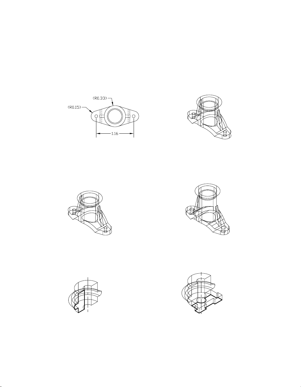
You work in the Part Modeling environment to create single parts.
In this environment, only one part can exist in a drawing. Additional parts
become unconsumed toolbodies for the purpose of creating a combined part.
Use part files to build a library of standardized parts.
examples of single part files
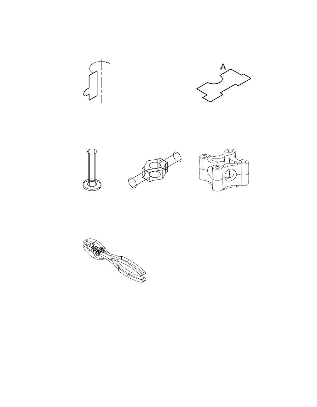
You work in Assembly Modeling to create multiple parts and assemblies.
In this environment, any number of parts can exist in one drawing. Parts can
be externally referenced from part and assembly files, or localized in the
assembly drawing.
assembly file containing four external part files
Mechanical Desktop Basics | 9
Page 24
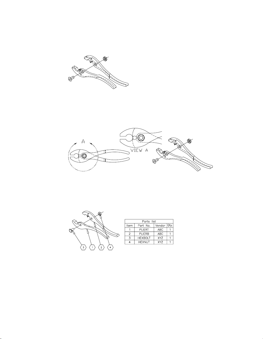
Individual parts can be fit together to create subassemblies and assemblies.
Assembly files contain more than one part. Parts are fit together using assembly constraints to define the positions of the individual parts that make up
your final product.
individual parts in an assembly file
completed assembly
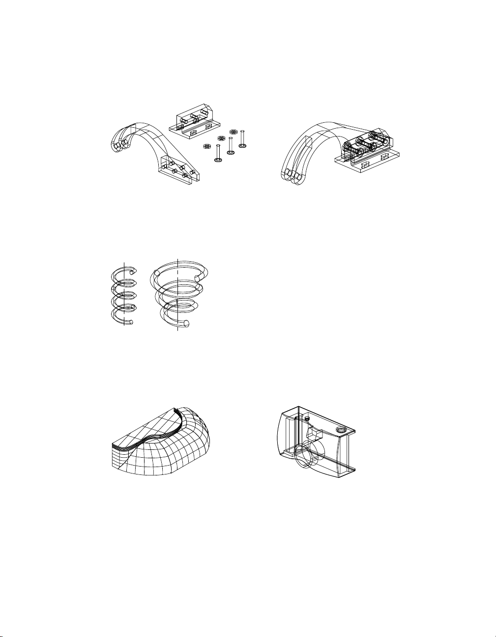
For standard parts, you can define different versions using a spreadsheet.
Instead of a large library of parts that differ only in size, like springs, bolts,
nuts, washers, and clamps, you can create one part and define different versions of that part in a spreadsheet that is linked to your drawing.
table driven part versions
You can also create 3D surface models.
Surface modeling is useful in the design of stamping dies, castings, or injection molds. You can also use surfaces to add to or cut material from a solid
part to create hybrid shapes.
surfaces used to create a part
surface cut applied to a part
10 | Chapter 2 Modeling with Autodesk Mechanical Desktop
Page 25
You can create scenes to define how your design fits together.
To better conceptualize the position of the parts in your assembly, you define
scenes using explosion factors, tweaks, and trails that illustrate how your
design is assembled.
exploded scene
You can create base, orthogonal, isometric, section, and detail views.
To document your design, drawing views can be created from scenes, parts,
or groups of selected objects. Any design changes are automatically updated
in these drawing views.
parametric drawing views
Add annotations and additional dimensions to finalize your documentation.
After you have created drawing views, finalize your design by adding balloons, bills of material, notes, reference dimensions, and mechanical
symbols.
annotations added to drawing
Mechanical Desktop Basics | 11
Page 26

12
Page 27

The User Interface
In This Chapter
3
When you start the Autodesk® Mechanical Desktop® 6
software, a page called the Today window is displayed.
This chapter provides an overview of the options on the
Today window to help manage your work, collaborate
with others, and link to information on the Web.
Information about the work environments and the user
interface are included to help you get started using the
Mechanical Desktop software.
The Today window
■
■ Work environm e nts
■ Mechanical Desktop interface
■ Working in the Browser
■ Methods for issuing commands
13
Page 28

Mechanical Desktop Today
The first time you open the Mechanical Desktop 6 program, the Today window
is displayed on top of the program interface, along with instructions about how
to use it. The Today feature is a powerful tool that makes it easy to manage drawings, communicate with design teams, and link directly to design information.
In the Today Window, you can expand the following options for access to the
the services you require.
My Workplace Connect directly to files on your computer and your local
network.
My Drawings Open existing drawings, create new ones, or access
symbol libraries.
Bulletin Board Post your own Web page with links to block libraries, CAD
standards, or other folders and directories on your
company network. CAD managers can use the Bulletin
Board to communicate with their design teams. An HTML
bulletin board template is provided.
The Web Connect directly to the Internet.
Autodesk
Point A
You can close the Today Window and use the File menu to create new drawings or open existing drawings.
To reopen Today, in the Assist menu choose Mechanical Desktop Today.
If you prefer not to see the Today Window when you start Mechanical
Desktop, you can turn it off in Assist ➤ Options ➤ System ➤ Startup.
Link directly to design information and tools such as
Buzzsaw.com on the Web. Use the units converter, link to
Autodesk Web sites, and much more.
Login and create your free account. Customize the
information in Autodesk Point A for your specific needs.
14 | Chapter 3 The User Interface
Page 29

Mechanical Desktop Environments
Mechanical Desktop has two working environments: Assembly Modeling
and Part Modeling.
Assembly Modeling Environment
This is the environment Mechanical Desktop uses when you start the
program or create a new file by using File ➤ New. Any number of parts and
subassemblies can coexist in the same drawing.
The advantages of the Assembly Modeling environment are
■ More than one part can be created in the same drawing.
■ Individual part files, and other assemblies or subassemblies, can be exter-
nally referenced or localized and used to build a complex assembly.
■ Different versions of a part can be displayed in the same file.
■ Scenes containing explosion factors, tweaks, and trails can be created.
There are three modes in the Assembly Modeling environment: Model,
Scene, and Drawing.
Model Mode
In Model mode, you create as many parts as you need. Parts may be local or
externally referenced. Create subassemblies and save them for use in larger
assemblies. Build assemblies from any number of single part files, subassemblies, and assemblies. You can also generate a BOM (Bill of Material) database
so a list of parts can be placed in your final drawing.
Scene Mode
In Scene mode, you set explosion factors for your assembled parts and create
tweaks and trails. These settings govern how your drawing views represent
your assemblies.
Drawing Mode
In an assembly file, you can place balloons to reference the parts in your
assembly. You can create a parts list with as much information as you need
to define your parts. To illustrate how parts in an assembly fit together, you
can create base views on exploded scenes.
Mechanical Desktop Environments | 15
Page 30

Part Modeling Environment
To begin a new drawing in the Part Modeling environment, choose File ➤
New Part File. Only one part may exist in the drawing. If you add more parts,
they automatically become unconsumed toolbodies. You use toolbodies to
create complex combined parts.
The advantages of the Part Modeling environment are
■ A library of standard parts can be created for use in assembly files.
■ The interface is streamlined to allow only those commands available in a
part file.
■ File sizes are minimized because the database doesn’t need additional
assembly information.
There are two modes in the Part Modeling environment: Model and Drawing.
Model Mode
In Model mode, you build and modify your design to create a single parametric part. The part takes the name of the drawing file.
Drawing Mode
In Drawing mode, you define views of your part and place annotations for
documentation. You can also create a parts list and balloons to reference a
combined part and its toolbodies.
16 | Chapter 3 The User Interface
Page 31

Mechanical Desktop Interface
When you open a new or existing drawing in Mechanical Desktop 6, four
toolbars and the Desktop Browser are displayed.
■ The Mechanical Main toolbar provides quick access to select commands
from the AutoCAD Standard and the Object Properties toolbars, some
Mechanical Desktop commands, and the Web. Icons are available for
direct links to Mechanical Desktop Today window and Web tools such as,
Point A, Streamline, RedSpark, MeetNow, Publish to Web, and eTransmit.
■ The Desktop Tools toolbar acts as a toggle, giving you quick access to Part
Modeling, Assembly Modeling, Scenes, and Drawing Layout.
■ The Part Modeling toolbar is the default, but, when you use the Desktop
Tools toolbar or the Desktop Browser to switch modes, the toolbar repre-
senting the mode you have chosen is displayed.
■ The Mechanical View toolbar is designed to give you full control over how
you view your models, including real-time pan, zoom, dynamic 3D
rotation, and shading commands.
■ The Desktop Browser is docked at the left side of the screen.
Desktop Tools toolbar
Mechanical Main toolbar
Help
Mechanical View toolbar
Desktop Browser
Part Modeling toolbar
Mechanical Desktop Interface | 17
Page 32
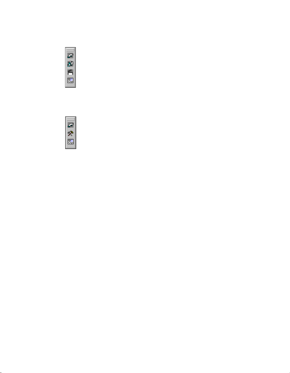
There are four main toolbars controlled by the Desktop Tools toolbar: Part
Modeling, Assembly Modeling, Scene, and Drawing Layout.
Part Modeling
Assembly Modeling
Scene
Drawing Layout
If you begin a drawing in the Part Modeling environment, the Desktop Tools
toolbar changes to display three buttons that control the Part Modeling,
Toolbody Modeling, and Drawing Layout toolbars.
Part Modeling
Toolbody Modeling
Drawing Layout
In addition to controlling the Mechanical Desktop toolbars, the Desktop
Tools toolbar switches between Part, Toolbody/Assembly, Scene, and
Drawing modes.
For a complete description of Mechanical Desktop toolbars, see appendix A,
“Toolbar Icons.”
Desktop Browser
When you start Mechanical Desktop 6, the Desktop Browser is displayed in
the default position at the left of your screen.
Docking the Desktop Browser
Right-click the gray area at the top of the Browser for a context menu of docking
controls. You can turn the following Browser docking options on and off.
Allow Docking With Docking on, you can drag a corner of the Browser to
change its shape and size, and you can drag the Browser
to a new location on your screen.
To return the Browser to its default position, turn on
Allow Docking, and double-click the Browser title bar.
18 | Chapter 3 The User Interface
Page 33
AutoHide With AutoHide on, choose Collapse to minimize the
Browser. When you move the cursor over and off of the
Browser, it expands and collapses.
Choose Right or Left to hide the Browser off a side of the
screen. When you move your cursor to the corresponding
edge of the screen, the Browser is displayed. Move the
cursor off the Browser, and it is hidden again.
To turn AutoHide off, in the Browser docking menu
choose AutoHide ➤ Off.
Hide Hides the Browser entirely. To restore it, in the Desktop
menu choose View ➤ Display ➤ Desktop Browser.
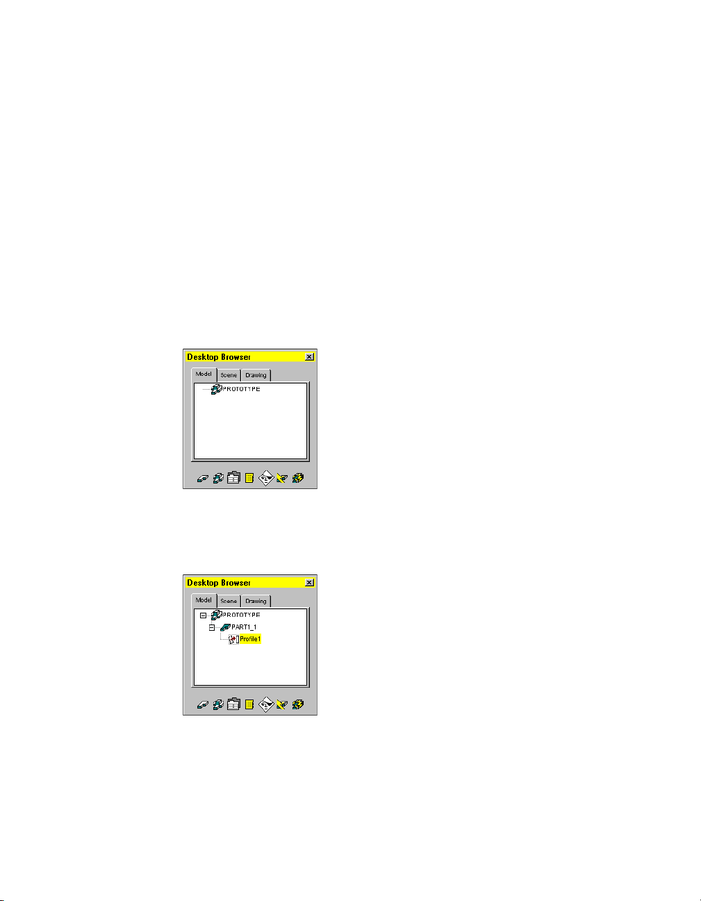
Working with the Desktop Browser
When you begin, Mechanical Desktop starts a new drawing in the Assembly
Modeling environment. The assembly is named for the current file.
When you create the first sketch, a part is automatically named, numbered,
and represented in the Browser. Because the first thing you create is a sketch,
it is nested under the part. As these objects are created, they are displayed
automatically in a hierarchy.
In the Browser, you can show as much or as little detail as you wish. When
there is more information, a plus sign is shown beside an object. You click
the plus sign to reveal more levels.
Mechanical Desktop Interface | 19
Page 34

You collapse levels by clicking the minus sign beside an object, or collapse
the entire hierarchy by right-clicking the assembly name and choosing
Collapse from the menu.
When you start a new drawing in the Part Modeling environment, or open
an existing part file, the Desktop Browser contains two tabs: Model and
Drawing. In the Assembly Modeling environment, the Browser contains
three tabs: Model, Scene, and Drawing. You can choose the tabs at the top of
the Browser window to navigate from one mode to another.
Part Modeling environment
Icons at the bottom of the Browser provide quick access to frequently-used
commands.
Assembly Modeling environment
Using the Browser in Part Modeling
When you are working in the Part Modeling environment, the Browser
contains two tabs: Model and Drawing.
Model Mode in Part Modeling
In Model mode, seven icons are displayed at the bottom of the Browser.
The two at the left are quick filters. These filters are available so that you can
control the visibility of features and assembly constraints in the Browser
when you are creating combined parts.
20 | Chapter 3 The User Interface
Page 35

The first icon, the Part filter, controls the display of assembly constraints
attached to a part and its toolbodies. If the Part filter is selected, only the
features of your part and its toolbodies are visible in the Browser. If it is not
selected, assembly constraints are also visible.
The second icon is the Assembly filter. If you select this filter, only assembly
constraints that are attached to your part and its toolbodies are visible.
The third icon accesses the Desktop Options dialog box where you control
the settings for your part, surfaces, drawing views, and miscellaneous desktop
preferences.
The middle icon provides immediate access to the Part Catalog. You use the
Part Catalog to attach and localize external part files, and instance external
and local parts in your current file for the purpose of creating combined parts.
The fifth icon opens the Desktop Visibility dialog box where you control the
visibility of your part, toolbodies, and drawing objects. The sixth icon
updates your part after you have made changes to it, and the last icon
updates assembly constraints if you are working with a combined part.
Drawing Mode in Part Modeling
In Drawing mode, six icons are displayed at the bottom of the Browser.
The first two icons on the left are toggles to control automatic updating of
your drawing views or part. The last four icons access desktop options,
control visibility, and manually update your drawing views or part.
Mechanical Desktop Interface | 21
Page 36

Using the Browser in Assembly Modeling
In the Assembly Modeling environment, the Browser displays three tabs:
Model, Scene, and Drawing. With these tabs, you can create multiple parts,
assemblies, scenes, BOMs, and documents, and you can reorder assemblies.
You can localize and externalize parts in the Browser without opening the
Assembly Catalog.
Model Mode in Assembly Modeling
Model mode in the Assembly Modeling environment has the same icons at
the bottom of the Browser as Model mode in the Part Modeling environment.
Because you are working in the Assembly environment, these icons provide
more functionality.
The first icon is the Part filter which you use to control the display of the
features that make up your parts. If the Part filter is selected, only part
features are visible in the Browser. If it is not selected, assembly constraints
are also visible.
The second icon is the Assembly filter. When you select this filter, only the
assembly constraints attached to your parts are visible.
The third icon opens the Mechanical Options dialog box. From this dialog
box you can manage your settings and standards for parts, assemblies,
surfaces, drawings, shaft generators, calculations, standard parts, and various
desktop preferences.
The middle icon provides access to the Assembly Catalog, a powerful interface for attaching and localizing external part and assembly files as well as
instancing both external and local parts in your current assembly.
The fifth icon controls the visibility of parts, assemblies, drawing entities, layers,
and linetypes. The sixth icon updates the active part after you have made
changes to it, and the last icon updates the active assembly or subassembly.
22 | Chapter 3 The User Interface
Page 37

Scene Mode in Assembly Modeling
In Scene mode, three icons are displayed at the bottom of the Browser.
The first icon accesses Desktop Options, where you can control the settings
for scenes. The second icon accesses Desktop Visibility, where you can
control the visibility of your parts, assemblies, and individual drawing
objects. The last icon updates the active scene.
Drawing Mode in Assembly Modeling
In Drawing mode, six icons perform the same functions as those in Drawing
mode in the Part Modeling environment.
Mechanical Desktop Interface | 23
Page 38

Issuing Commands
You can issue commands in several ways:
■ Select an option from a right-click menu in the Desktop Browser.
■ Select an option from a right-click menu in the active screen area of your
drawing.
■ Select a toolbar icon.
■ Select an option from a pull-down menu.
■ Enter the command name on the command line.
■ Use an abbreviation of the command, called an accelerator key, on the
command line.
Using Command Menus in the Desktop Browser
Many of the commands in Mechanical Desktop can be accessed using the
Browser menus. The Browser has two types of menus. One you activate by
right-clicking an existing object in the Browser. The other you activate by
right-clicking the Browser background. Options that are not available are gray.
The type of object you select with a right-click determines the menu displayed.
The mode you are in, Model, Scene, or Drawing, when you right-click the
Browser background determines the menu displayed.
24 | Chapter 3 The User Interface
Page 39

Using Context Menus in the Graphics Area
In addition to the Browser menus, context-sensitive menus are available in
the graphics area during the modeling process. When you start Mechanical
Desktop, the Part menu is available in the graphics area. You can toggle
between the Part and Assembly menus as you build your models. When you
are in Scene mode, the Scene menu is available. In Drawing mode, you can
toggle between the Drawing and Annotate menus.
Using Toolbars
Toolbars have icons to represent frequently-used commands, settings, and
environments. You can choose an icon instead of selecting a command from
a menu or entering its name on the command line. When you pause with
the mouse selection arrow on an icon, the command action is shown at the
bottom of the screen. A tooltip also appears under the cursor. Click the left
mouse button to select the command.
Some icons have a subtoolbar (flyout) with related icons. If the icon has a
small arrow in the lower right corner, drag the mouse to reveal the additional
icons, and then select one.
To hide a toolbar, click the button in its upper right corner. To unhide it,
right-click any toolbar. In the pop-up menu, select the toolbar to redisplay.
The toolbar is automatically redisplayed.
To reorient the Mechanical Desktop toolbars to their default positions,
choose View ➤ Toolbars ➤ Desktop Express (Left). If you prefer the toolbars
at the right of your screen, choose Desktop Express (Right).
You may want to view larger toolbar icons. To do so, right-click any toolbar
and choose Customize. Select Large Buttons at the bottom left of the Toolbars
dialog box.
If you choose Large Buttons and then dock the toolbars in the screen header
area above the command line or at either side of the screen, some icons may
not be visible. In that case, you can drag the toolbar onto the screen.
Mechanical Desktop Interface | 25
Page 40

Using Pull-down Menus
To select a menu option, or access a submenu, hold down the left mouse
button while you navigate through the menu. When you find the command
you want to use, release the mouse button.
You can also access menu commands by using the keyboard. Hold down
while selecting the underlined letter of the menu option. For example, to
AMPROFILE from the keyboard, press ALT, then P, S, P.
select
ALT
Selecting Command Options from Dialog Boxes
Many commands have options within dialog boxes. As the term dialog box
suggests, you interact by selecting options to make a particular setting active,
display a list from which to choose an option, or enter a specific value. If a
command has a dialog box, it is displayed when you access the command,
regardless of whether you did so on the command line or from a menu or
toolbar icon.
When you need information about a dialog box you are working with, click
the Help button located in the dialog box.
NOTE If the Mechanical Desktop dialog boxes do not display, on the
command line enter CMDDIA, and change the system variable to 1.
Using the Command Line
You can access a command or system variable directly by entering its name
on the command line. Many experienced users prefer this method because it
is faster than using menus. Some experienced users are familiar with specifying command options from the command line and prefer to turn off the
display of dialog boxes.
However, because many Mechanical Desktop commands require input
through their dialog boxes, it is recommended that you use the dialog boxes
instead of the command line to ensure that you have access to the full
functionality of each feature.
All the commands and system variables for Mechanical Desktop and
AutoCAD are documented in Help.
Using Accelerator Keys
Many commands also have shortcuts called accelerator keys. To issue a
command using an accelerator key, simply enter the command alias on the
command line.
For a complete list of Mechanical Desktop accelerator keys, see “Accelerator
Keys” in the Command Reference in Help.
26 | Chapter 3 The User Interface
Page 41

Documentation and Support
In This Chapter
4
This chapter provides an overview of the printed and
®
online documentation provided with Autodesk
®
Mechanical Desktop
product learning, training, and support.
Read this section so that any time you need product
information, you will know where to locate it.
6. It guides you to resources for
Mechanical Desktop print
■
documentation
■ Mechanical Desktop online
documentation
■ Product Support Assistance in
Help
■ Mechanical Desktop learning
and training
■ Your Internet resources
27
Page 42

Printed and Online Manuals
The extensive set of printed and online documentation provided with your
purchase of Mechanical Desktop 6 software includes the printed Autodesk
Mechanical Desktop 6 User’s Guide, AutoCAD Mechanical 6 User’s Guide, and the
AutoCAD 2002 User’s Guide.
The online AutoCAD Mechanical 6 and Mechanical Desktop 6 Installation Guide
is provided on the product CD.
All of the Mechanical Desktop 6 manuals are available in PDF format on the
product CD, and on the Mechanical Desktop product page of the Autodesk
Web site at http://www.autodesk.com/mechdesktop ➤ Product Information ➤
Online and Print Manuals.
Mechanical Desktop Printed Manual
The printed Autodesk Mechanical Desktop 6 User’s Guide is divided into two
parts.
Part I An introduction to the product and information you need
to get started using the software.
Part II A set of tutorials to expand your skills in using Mechanical
Desktop and understanding mechanical design.
Chapters 5 through 21 focus on Mechanical Desktop,
while chapters 22 through 24 focus on Mechanical
Desktop with the power pack.
AutoCAD Printed Manual
The printed AutoCAD User’s Guide contains comprehensive information and
instructions for using AutoCAD. This manual is also available online in the
AutoCAD Help.
Online Installation Guide
The AutoCAD Mechanical 6 and Mechanical Desktop 6 Installation Guide is
available on the product CD. It provides the following information:
Introduction What’s in the software.
Chapter 1 System requirements and recommendations for installing
and running the software.
28 |Chapter 4 Documentation and Support
Page 43

Chapter 2 Procedures to install, upgrade, authorize, and maintain
the software for a single user, and information you need
to know before you begin your installation.
Chapter 3 Information for network administrators. Instructions for
installing and configuring for a network environment.
Chapter 4 Technical information about environment variables and
performance enhancements to optimize performance of
the software.
Chapter 5 Information about cabling and option settings, plus other
information necessary to link and configure plotters and
printers with AutoCAD Mechanical/Mechanical Desktop.
Chapter 6 Instructions to uninstall the software, maintain your hard
disk, and recover data in case of a system failure.
AutoCAD 2002 Documentation
You should be familiar with AutoCAD before you use Mechanical Desktop.
The complete set of AutoCAD 2002 documentation is available in the
AutoCAD Help. It includes:
■ User’s Guide*
■ Command Reference*
■ Customization Guide*
■ ActiveX
■ ActiveX
■ AutoLISP
■ Visual LISP
■ Visual LISP
■ DXF
■ Driver Peripheral Guide
■ Connectivity Automation Reference
■ Network Administrator’s Guide
®
and VBA Developer’s Guide*
®
and VBA Reference
®
Reference
TM
Developer’s Guide*
TM
TM
Tutorial*
Reference
AutoCAD 2002 manuals marked with an asterisk can be ordered in print from
your local reseller.
The AutoCAD 2002 Learning Assistance CD that is included in your package
is a multimedia learning tool for intermediate to experienced AutoCAD users.
If you currently own a valid license for an Autodesk product and require
replacement media or documentation, please call the Customer Service
Center at 1-800-538-6401 to order.
Printed and Online Manuals | 29
Page 44

Mechanical Desktop Help
The Help in Mechanical Desktop provides integrated information about
AutoCAD Mechanical and Mechanical Desktop.
The Help is formatted for easy navigation, and includes:
■ Content organized by the major functional areas of Mechanical Desktop,
with How To, Reference, and Learn About pages for each functional area
■ Specific information about each of the features in the program
■ Concepts and procedures for the new features in this release
■ A keyword index, search function, and Favorites tab
■ Printable Command Reference
■ Guides to system variables and accelerator keys
■ Access to Support Assistance with integrated links to solutions
For access to Help, you can choose from the following methods:
■ From the Help menu, select Mechanical Help Topics.
■ Select the Help button in the standard toolbar.
■ Press F1. This opens the topic for an active button or command.
■ Click the Help button within a dialog box.
Updating Help Files
If you have access to the Internet, you can download updated Help files from
the Autodesk Web site.
To update your Help files
1 In Mechanical Desktop Today, choose Autodesk Point A. In Useful Autodesk
Links, choose Autodesk Product Support Index.
2 Follow the links to Mechanical Desktop 6 product support and updates.
30 |Chapter 4 Documentation and Support
Page 45

Product Support Assistance in Help
When you need product support, refer to Support Assistance in the Help
menu. Support Assistance ensures quick access to technical support information through an easy-to-use issue/solution format with self-help tools and a
knowledge base.
Product Support Assistance provides information about support options
available from resellers, Autodesk System Centers (ASCs), user groups in your
area, and those available directly from the Autodesk Web pages, including
the Autodesk Product Support Index.
Updating the Support Assistance Knowledge Base
You can update your Support Assistance knowledge base with the latest
support information about Mechanical Desktop by using the
Documentation Update utility in the Support Assistance Welcome.
To update your Support Assistance Knowledge Base
1 From the Help menu, choose Support Assistance, then choose Download.
2 Follow the prompts to update your knowledge base.
Learning and Training Resources
Many sources for learning and training are listed on the Mechanical Desktop
Learning and Training Web page. From the Mechanical Desktop Web site at
http://www.autodesk.com/mechdesktop, navigate to Learning and Training. You
can link directly to sources for
■ Online courses and tutorials
■ The Autodesk Official Training Courseware (AOTC)
■ A list of Autodesk authorized resellers and trainers
Autodesk Official Training Courseware (AOTC) is the Autodesk-endorsed
courseware for instructor-led training. To register for a training course,
contact an Authorized Autodesk Training Center, Authorized Autodesk
Reseller, or Autodesk System Center.
Product Support Assistance in Help | 31
Page 46

Internet Resources
Following are resources for information about Autodesk products and assistance with your Mechanical Desktop questions.
■ Autodesk Web site: http://www.autodesk.com
■ Mechanical Desktop home page at the Autodesk Web site:
http://www.autodesk.com/mechdesktop
■ AutoCAD Mechanical home page at the Autodesk Web site
http://www.autodesk.com/autocadmech
■ Mechanical Desktop discussion groups:
http://www.autodesk.com/mechdesktop-discussion
■ AutoCAD Mechanical discussion groups:
http://www.autodesk.com/autocadmech-discussion
■ To locate an authorized reseller in your area, go to:
http://www.autodesk.com/support.
32 |Chapter 4 Documentation and Support
Page 47

Part II
Autodesk® Mechanical
Desktop
The tutorials in this section teach you how to use Mechanical Desktop 6, and provide a
comprehensive overview of mechanical design. The lessons range from basic to advanced,
and include step-by-step instructions and helpful illustrations.
You learn how to create parts, surfaces, assemblies, table driven parts, and bills of material.
You will also learn how to prepare your designs for final documentation. Specific drawing
files for each lesson are included with the program. These drawing files provide design
®
Tutorials
elements that help you understand and learn mechanical design concepts.
There are lessons designed for learning to model with Mechanical Desktop, and others
designed specifically for learning to use Mechanical Desktop with the power pack.
33
Page 48

34 |
Page 49

Using the Tutorials
In This Chapter
5
This Introduction presents information that is useful to
know before you start performing the tutorials for
®
Autodesk
of how the tutorials are structured, and the methods
you can use to issue commands. You learn how to
manipulate the position of the Browser to best suit your
work space.
As you work through the tutorials, you use a set of
drawing files that are included with your software. In
this section, you learn how to locate, back up, and
maintain these drawings.
Mechanical Desktop®. It provides a summary
Finding the right tutorial
■
■ Accessing commands
■ Controlling the appearance of
the Desktop Browser
■ Backing up tutorial files
35
Page 50

How the Tutorials are Organized
Read the Key Terms and Basic Concepts sections at the beginning of each
tutorial before you begin the step-by-step instructions. Understanding this
information before you begin will help you learn.
Key Terms Lists pertinent mechanical design terms and definitions
for the lesson.
Basic Concepts Gives you an overview of the design concepts you learn in
the lesson.
The tutorials begin with basic concepts and move toward more advanced
design techniques. They are presented in three design categories: part modeling, assembly modeling, and surface modeling.
For best results, run Mechanical Desktop 6 to perform the tutorials in chapters 1 through 16, and Mechanical Desktop 6 with the power pack to perform
chapters 17 through 19.
Chapters 6 Through 15 Part Modeling
These tutorials guide you through the basics of part modeling. Starting with
a basic sketch, you learn how to create fully parametric feature-based models
and generate drawing views.
Chapters 16 Through 18 Assembly Modeling
The assembly modeling tutorials show you how to create, manage, and document complete assemblies and subassemblies, and create exploded views of
your assembly design. You also learn how to use assembly techniques to
build a combined part in the Part Modeling environment.
Chapters 19 Through 21 Surface Modeling
These tutorials cover the techniques of surface modeling. You start by learning how to create and edit different types of surfaces. Then you create a surface and use it to cut material from a parametric part. You also learn how to
surface a wireframe model from the ground up.
Chapters 22 Through 24 2D and 3D Parts and Calculations
These tutorials focus on features in the Mechanical Desktop 6 with the power
pack. Included are tutorials working with standard parts and the shaft
generator and 3D finite element analysis (FEA) features. The exercises in
these tutorial chapters are designed to help you understand and use the
power pack features to simplify your work.
36 | Chapter 5 Using the Tutorials
Page 51

Accessing Mechanical Desktop Commands
Mechanical Desktop provides several methods to access commands and
manage your design process.
The following are samples of the access methods available to you:
Browser Right-click the window background and choose New Part.
Context Menu In the graphics area, right-click and choose Part ➤ New
Part.
Too lbutton New Part
Desktop Menu Part ➤ Part ➤ New Part
Command
The step-by-step procedures in the tutorials indicate the command name in
the opening procedural text. The appropriate toolbutton is displayed in the
margin next to the preferred access method. In the tutorials, the context
menu method is used when the menus are sensitive to what you are doing.
The Browser method is used when you can save time and steps. You can use
any of the alternate methods as well.
If you are in Model mode, you can toggle between the Part and Assembly
context menus. If you are in Scene mode, the Scene menu is available. When
you are working in Drawing mode, you can toggle between the Drawing and
Annotate context menus.
Here is an example of how methods are used in the tutorials:
AMNEW to create a new part.
3 Use
Context Menu In the graphics area, right-click and choose Part ➤ New
AMNEW
Part.
NOTE To find the location of a particular toolbutton, refer to Appendix A.
Accessing Mechanical Desktop Commands | 37
Page 52
Positioning the Desktop Browser
The Desktop Browser is a graphical interface that is useful in both creating
and modifying your designs. You can do much of your work in the Browser
as you proceed through the lessons in the tutorials.
By default, the Browser is located on the left side of your screen. You may
want to move, resize, or hide the Browser to suit your working conditions.
This section provides instructions to control the size, shape, and location of
the Browser, and to return it quickly to the default location.
The Browser behaves differently when it is in the Auto Hide state. The following are procedures for positioning the Browser both in and out of the Auto
Hide state.
To minimize and expand the Desktop Browser
To minimize the Browser double-click the gray area above the tabs.
To expand the Browser, double-click the gray area again.
To minimize the Browser in the Auto Hide state, right-click the gray area and
choose Auto Hide ➤ Collapse.
After you minimize the Browser in Auto Hide, you control the expand and
collapse function by moving your cursor onto and off of the Browser.
To turn off Auto Hide, right-click the gray area and choose Auto Hide ➤ Off.
With Auto Hide off, the Browser remains expanded when you move your cursor away from it.
To move the Browser out of the default position
To move the Browser to another location on the screen, right-click the title
bar and choose Move. Click the title bar and drag the Browser to a location
on your screen.
To return the Browser to the default position
To return the Browser to the default position, double-click the title bar. The
Browser is docked in the default position along the left side of the graphics
screen.
To return to the previous location, right-click the gray area and turn off Allow
Docking.
38 | Chapter 5 Using the Tutorials
Page 53

To hide and unhide the Browser
To hide the Browser, right-click the gray area above the tabs and choose Hide.
To unhide the Browser, choose View ➤ Display ➤ Desktop Browser.
To move the Browser off the screen with Auto Hide, right-click the gray bar
above the tabs and choose Auto Hide ➤ Left (or Right).
After you move the Browser off the left or right side of the screen with Auto
Hide, if you move your mouse to the corresponding edge of the screen, the
Browser is displayed along that edge. Move your mouse off the Browser, and
the Browser returns to the location off the screen.
To turn off Auto Hide, right-click the gray area and choose Auto Hide ➤ Off.
The Browser remains positioned on the screen when you move your cursor
away from it.
To move the Browser directly from Auto Hide to another location on your
screen, choose Auto Hide ➤ Allow Docking. Click the title bar and drag the
Browser to a new location. The Browser is docked in the new location.
To resize the Browser
Right-click the title bar and choose Size. Then drag a corner to resize the
Browser.
To return the Browser to its previous size, double-click the title bar.
Positioning the Desktop Browser | 39
Page 54

Backing up Tutorial Drawing Files
For each tutorial, you use one or more of the master drawing files that contain the settings, example geometry, or parts for the lesson. These files are
included with Mechanical Desktop. Before you begin the tutorials, back up
these drawing files so you always have the originals available. Any mistakes
you make while you are learning will not affect the master files.
To back up tutorial drawing files
1 From the Windows Start menu, choose Programs ➤ Windows Explorer.
2 In the folder where Mechanical Desktop is installed (by default this is Program
Files\Mdt\desktop), choose File ➤ New ➤ Folder.
3 Create a new folder called tutorial backup.
4 Open the desktop\tutorial folder that contains all the tutorial drawing files
and copy them into your new folder.
Now you can use the tutorial drawings in the desktop\tutorial folder as you
work through the tutorials in this book.
NOTE Keep your working tutorial files in the desktop\tutorial folder so that
external references in the assembly tutorials can update correctly.
40 | Chapter 5 Using the Tutorials
Page 55

Creating Parametric Sketches
In This Chapter
6
Autodesk® Mechanical Desktop® automates your design
and revision process using parametric geometry.
Parametric geometry controls relationships among
design elements and automatically updates models and
drawings as they are refined.
The sketch is the basic design element that defines the
approximate size and shape of features in your part. As
the name implies, a sketch is a loose approximation of
the shape that will become a feature. After a sketch is
solved, you apply parametric constraints to control its
shape.
After you learn to create sketches, move on to chapter 2
Analyzing a design and creating a
■
strategy for sketching
■ Text sketch profiles
■ Open profile sketches
■ Closed profile sketches
■ Path sketches
■ Cut line sketches
■ Split line sketches
■ Break line sketches
to learn how to add constraints to sketches.
41
Page 56

Key Terms
Te r m Definition
2D constraint Defines how a sketch can change shape or size. Geometric constraints control the
closed loop A polyline entity, or group of lines and arcs that form a closed shape. Closed loops
closed profile A constrained sketch that is a cross section or boundary of a shape, such as an
construction geometry Any line or arc created with a noncontinuous linetype. Using construction
cut line Used to specify the path of a cross-section drawing view. Unlike a profile sketch,
feature An element of a parametric part model. You can create extruded features,
nested loop A closed loop that lies within the boundary of another closed loop. Nested loops
open profile A profile created from one or more line segments sketched to form an open
path sketch A constrained sketch that is a trajectory for a swept feature.
shape and relationships among sketch lines and arcs. Dimensional constraints
control the size of sketch geometry.
are used to create profile sketches.
extrusion, a revolved feature, or a swept feature.
geometry in paths and profiles may mean fewer constraints and dimensions are
needed to control size and shape of symmetrical or geometrically consistent
sketches.
the cut line sketch is not a closed loop. There are two types of cut line sketches—
offset and aligned.
revolved features, loft features, and swept features using profiles and paths. You
can also create placed features like holes, chamfers, and fillets. You combine
features to create complete parametric part models.
are used to create more complex profile sketches.
shape. Open profiles are used in bend, rib, and thin wall features.
sketch A planar collection of points, lines, arcs, and polylines used to form a profile, path,
sketch tolerance Tolerance setting that closes gaps smaller than the pickbox and snaps lines to
split line A sketch, either open or closed, used to split a part into two distinct parts. Also
text sketch profile A profile created from a single line of text in a selected font and style. Text-based
split line, break line, or cutting line. An unconstrained sketch contains geometry
and occasionally dimensions. A constrained sketch, such as a profile, path, split
line, cut line, or break line that contains “real” and construction geometry, and is
controlled by dimensions and geometric constraints.
horizontal, vertical, parallel, or perpendicular.
known as a parting line.
profiles are used to emboss parts with text.
42 | Chapter 6 Creating Parametric Sketches
Page 57

Basic Concepts of Parametric Sketching
You create, constrain, and edit sketches to define a
■ Profile that governs the shape of your part or feature
■ Location for a bend feature in a part design
■ Path for your profile to follow
■ Cut line to define section views
■ Split line to split a face or part
■ Break line to define breakout section views
After you create a rough sketch with lines, polylines, arcs, circles, and ellipses
to represent a feature, you solve the sketch. Solving a sketch creates a parametric profile, path, cut line, split line, or break line from your sketched
geometry.
When you solve a sketch, Mechanical Desktop converts it to a parametric
sketch by applying two-dimensional constraints to it, according to internal
rules. This reduces the number of dimensions and constraints you need to
fully constrain it. In general, a sketch should be fully constrained before it is
used to create a feature.
You can control the shape and size of the parametric sketch throughout multiple design revisions.
In this tutorial, you learn to create and solve sketches. Chapter 7, “Constrain-
ing Sketches,” introduces you to creating, modifying, and deleting the con-
straints and parametric dimensions that control a sketch.
Basic Concepts of Parametric Sketching | 43
Page 58

Sketching Tips
Some of these tips do not apply to this chapter, but you will see their usefulness when you use sketches to create complex parts.
Tip Explanation
Keep sketches simple It is easier to work with a single object than a multiple-object
Repeat simple shapes If a design has repeating elements, sketch one and then copy or
Define a sketching
layer
Preset sketch
tolerances
Draw sketches to size When your sketches are roughly correct in size and shape, your
Use PLINE Whenever possible, use the PLINE command to create your
sketch. Combine simple sketches for complex shapes.
array as needed.
Specify a separate layer and color for sketching. Your sketch is
visible with other part geometry but easy to identify when you
need to modify it.
Define characteristics, such as sketch precision and angular
tolerance of sketch lines, if the default values are not sufficient.
design is less likely to become distorted as dimensions or
constraints are added. Sketch a rectangle to serve as a boundary
for the base feature to set relative size. Sketch the feature, but
delete the rectangle before you create a profile.
sketches. With PLINE, you can easily draw tangent lines and arcs.
44 | Chapter 6 Creating Parametric Sketches
Page 59
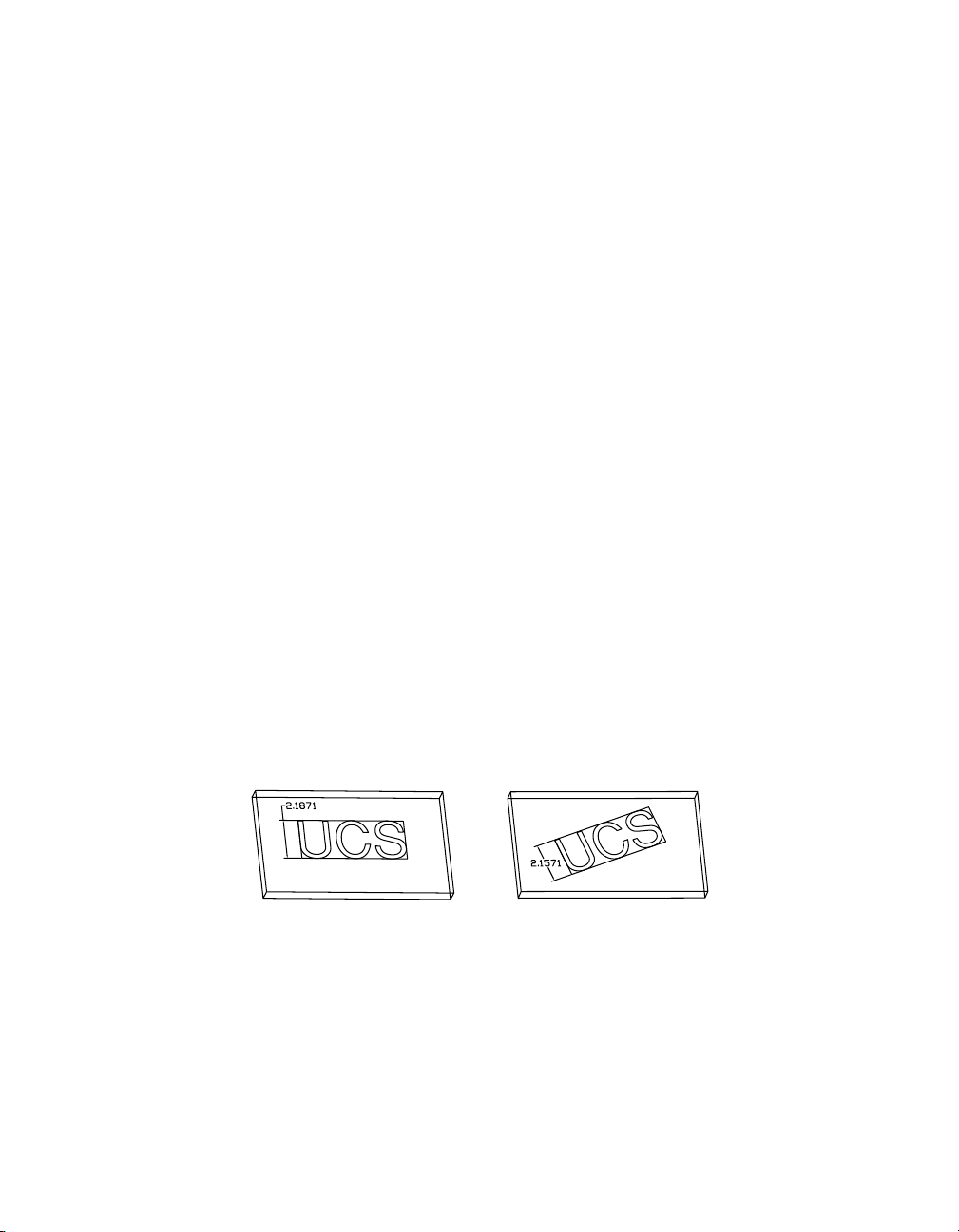
Creating Profile Sketches
In Mechanical Desktop, there are three types of profile sketches:
■ Text-based profiles, used to create parametric 3D text-based shapes
■ Open profile sketches, used to define features on parts
■ Closed profile sketches, used to outline parts and features
You can solve and apply parametric constraints and dimensions to all three
of these profile sketch types.
Creating Text Sketch Profiles
A text sketch profile is a line of text displayed in a rectangular boundary. You
extrude a text sketch profile to create the emboss feature on part models.
To create a text sketch profile, you use the command
opens where you can enter text and choose a font style and size, or you can
enter the information on the command line.
You define an anchor point for the rectangle on your part and a point to
define the height of the text. You have the option to define a rotation value
on the command line to position the text at an angle. As you move your cursor to define the anchor and height points, the rectangular boundary scales
appropriately to accommodate the size of the text.
You can change the size of the text by changing the value of the height
dimension. You can apply typical parametric dimensions and constraints
between the rectangular boundary and other part edges or features.
When the text sketch profile is sized correctly and in the right position on
your part, you extrude it to create the emboss feature.
text sketch text sketch with rotation defined
To learn more about using text sketch profiles in the emboss feature, see
“Creating Emboss Features” on page 140.
AMTEXTSK. A dialog box
Creating Profile Sketches | 45
Page 60

Creating Open Profile Sketches
You can create an open profile from single or multiple line segments, and
solve it in the same way as you solve a closed profile.
An open profile constructed with one line segment is used to define the location of a bend feature on a flat or cylindrical part model. To bend an entire
part, you sketch the open profile over the entire part. If you sketch the open
profile over a portion of a part, only that portion of the part bends.
Open profiles constructed with one or multiple line segments are extruded
to form rib features and thin features. For a rib feature, the open profile
defines the outline of the rib, and is sketched from the side view. For a thin
feature, the open profile defines the shape of a wall and is extruded normal
to the work plane.
profile for rib featureprofile for bend feature
To learn more about open profiles in features, see “Creating Bend Features”
on page 163, “Creating Rib Features” on page 133, and “Creating Thin Features” on page 136.
profile for thin feature
Creating Closed Profile Sketches
A profile sketch is a two-dimensional outline of a feature. Closed profile
sketches are continuous shapes, called loops, that you construct from lines,
arcs, and polylines. You use closed profile sketches to create features with custom shapes (unlike standard mechanical features such as holes, chamfers,
and fillets).
Profile sketches can be created from a set of objects, or a single polyline, that
defines one or more closed loops. You can use more than one closed loop to
create a profile sketch if the loops are nested within each other.
You cannot create profile sketches with loops that are
■ Self-intersecting
■ Intersecting
■ Tangential
■ Nested more than one level deep
46 | Chapter 6 Creating Parametric Sketches
Page 61

In this section, you create three profile sketches.
Open the file sketch1.dwg in the desktop\tutorial folder. This drawing file is
blank but it contains the settings you need to create these profiles.
NOTE Back up the tutorial drawing files so you still have the original files if you
make a mistake. See “Backing up Tutorial Drawing Files” on page 40.
Using Default Sketch Rules
Mechanical Desktop analyzes individual geometric elements, and operates
on a set of assumptions about how they should be oriented and joined.
rough sketch profile sketch
Before you begin, look at the Desktop Browser. It contains an icon with the
drawing file name. There are no other icons in the Browser, which indicates
that your file contains no parts.
You can move the Browser on your desktop and resize it to give yourself more
drawing area. See “Positioning the Desktop Browser” on page 38.
Creating Profile Sketches | 47
Page 62

To create a profile sketch from multiple objects
LINE to draw this shape, entering the points in the order shown.
1 Use
Context Menu In the graphics area, right-click and choose 2D Sketching
➤ Line.
Specify first point: Specify a point (1)
Specify next point or [Undo]: Specify a second point (2)
Specify next point or [Undo]: Specify a third point (3)
Specify next point or [Close/Undo]: Specify a fourth point (4)
Specify next point or [Close/Undo]: Specify a fifth point (5)
Specify next point or [Close/Undo]: Specify a sixth point (6)
Specify next point or [Close/Undo]: Specify a seventh point (7)
Specify next point or [Close/Undo]: Specify an eighth point (8)
Specify next point or [Close/Undo]: Press
ENTER
1
4
3
2
8
5
7
6
You do not need to make the lines absolutely vertical or horizontal. The
objective is to approximate the size and shape of the illustration.
2 Using
ARC, sketch the top of the shape, following the prompts on the
command line.
Context Menu In the graphics area, right-click and choose 2D Sketching
➤ Arc.
Specify start point of arc or [CEnter]: Specify the start point (9)
Specify second point of arc or [CEnter/ENd]: Specify the second point (10)
Specify end point of arc: Specify the endpoint (11)
10
911
You do not need to use
OSNAP to connect the arc to the endpoints of the
lines.
48 | Chapter 6 Creating Parametric Sketches
Page 63
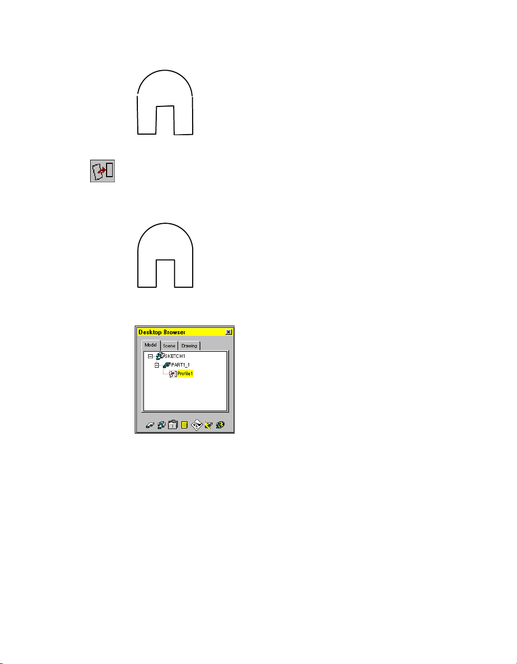
Your sketch should look like this.
3 Create a profile sketch from the rough sketch, responding to the prompts.
Context Menu In the graphics area, right-click and choose Sketch Solving
➤ Profile.
Select objects for sketch: Select the arc and the lines
Select objects for sketch: Press
ENTER
As soon as the sketch is profiled, a part is created. The Browser contains a new
icon labelled PART1_1. A profile icon is nested under the part icon.
According to internal sketching rules, Mechanical Desktop determines
whether to interpret the sketch geometry as rough or precise and whether to
apply constraints.
By default, Mechanical Desktop interprets the sketch as rough and applies
constraints, redrawing the sketch. You can customize these default settings
with Mechanical Options.
Creating Profile Sketches | 49
Page 64
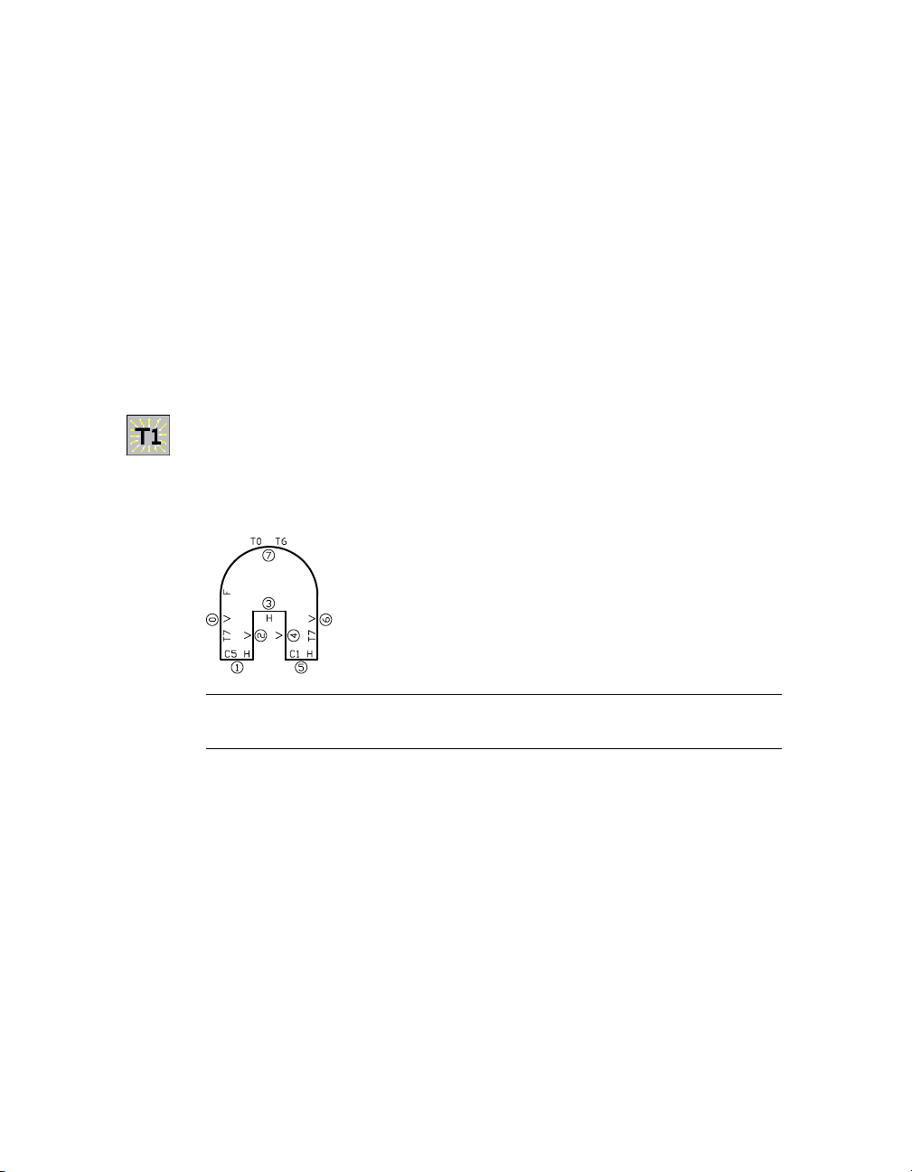
When redrawing, Mechanical Desktop uses assumed constraints in the
sketch. For example, lines that are nearly vertical are redrawn as vertical, and
lines that are nearly horizontal are redrawn as horizontal.
After the sketch is redrawn, a message on the command line tells you that
Mechanical Desktop needs additional information:
Solved under constrained sketch requiring 5 dimensions or constraints.
Depending on how you drew your sketch, the number of dimensions
required to fully constrain your sketch may differ from that in this exercise.
This message tells you that the sketch is not fully defined. When you add the
missing dimensions or constraints, you determine how the sketch can
change throughout design modifications. Before you add the final constraints, you need to show the assumed constraints.
AMSHOWCON to show the existing constraints, following the prompt.
4 Use
Context Menu In the graphics area, right-click and choose 2D
Constraints ➤ Show Constraints.
Enter an option [All/Select/Next/eXit] <eXit>: Enter a
The constraint symbols are displayed.
NOTE The numbers in your sketch might differ, depending on the order in
which you created the geometric elements.
The sketch has eight geometric elements, seven lines and an arc, each identified by a number in a circle. Four lines have a V symbol (vertical) and three
lines have an H symbol (horizontal). Two of the horizontal lines have constraints denoted by symbols that begin with the letter C (collinear), and three
of the elements have constraints denoted by symbols that begin with the
letter T (tangent).
50 | Chapter 6 Creating Parametric Sketches
Page 65

If your sketch does not contain the same constraints, redraw it to more
closely resemble the illustrations in steps 1 and 2.
Notice the letter F, located at the start point of line 0. It indicates that a fix
constraint has been applied to that point. When Mechanical Desktop solves
a sketch, it applies a fix constraint to the start point of the first segment of
your sketch. This point serves as an anchor for the sketch as you make
changes. It remains fixed in space, while other points and geometry move
relative to it.
You may delete this constraint if you wish, and apply one or more fix constraints to the endpoints of sketch segments, or to the segments themselves,
in order to make your sketch more rigid.
5 To hide the constraints, respond to the prompt as follows:
Enter an option [All/Select/Next/eXit] <eXit>: Press
Save your file.
You have successfully created a profile sketch. In chapter 7, “Constraining
Sketches,” you learn to create, modify, and delete constraints and parametric
dimensions.
ENTER
Using Custom Sketch Rules
Custom settings affect how Mechanical Desktop analyzes rough sketches. In
this exercise, you sketch with
sketch. You will modify one of the Mechanical Options sketch rule settings
and see its effect on the sketch.
PLINE and convert your drawing to a profile
rough sketch profile sketch
Before you begin the next exercise, create a new part definition.
Creating Profile Sketches | 51
Page 66
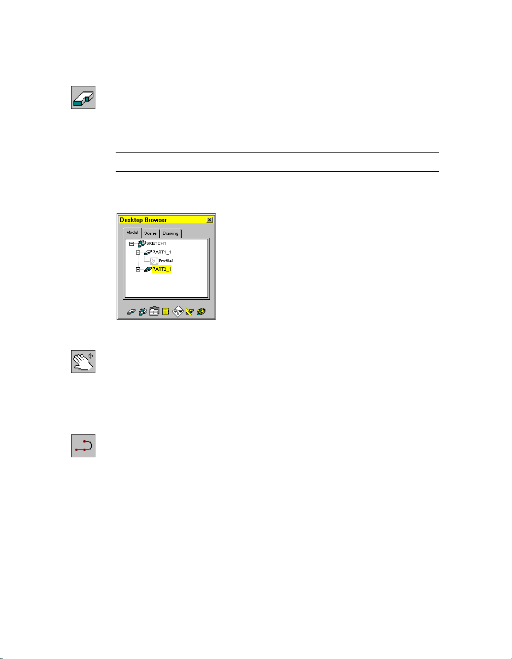
To create a new part definition
1 Use the context menu to initiate a new part definition.
Context Menu In the graphics area, right-click and choose Part ➤ New
Part.
2 Respond to the prompts as follows:
Select an object or enter new part name <PART2>: Press
ENTER
NOTE The command method you use determines which prompts appear.
A new part definition is created in the drawing and displayed in the Browser.
The new part automatically becomes the active part.
3 Pan the drawing so you have room to create the next sketch.
Context Menu In the graphics area, right-click and choose Pan.
You are ready for the next exercise.
To create a profile sketch from a single polyline
1 Use
PLINE to draw this rough sketch as a continuous shape, following the
prompts for the first four points.
Context Menu In the graphics area, right-click and choose 2D Sketching
➤ Polyline.
Specify start point: Specify a point (1)
Current line-width is 0.0000
Specify next point or [Arc/Close/Halfwidth/Length/Undo/Width]:
Specify a second point (2)
Specify next point or [Arc/Close/Halfwidth/Length/Undo/Width]:
Specify a third point (3)
Specify next point or [Arc/Close/Halfwidth/Length/Undo/Width]:
Specify a fourth point (4)
52 | Chapter 6 Creating Parametric Sketches
Page 67
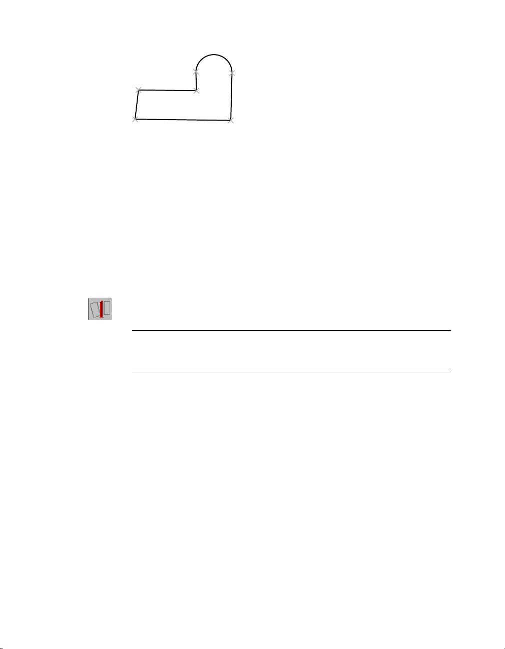
5
1
6
4
2
3
2 Following the prompts, switch to Arc to create the arc segment, then switch
back to Line. Switch to Close to finish the sketch.
Specify next point or [Arc/Close/Halfwidth/Length/Undo/Width]: Enter a
Specify endpoint of arc or
[Angle/CEnter/CLose/Direction/Halfwidth/Line/Radius/Second pt/Undo/Width]:
Specify a fifth point (5)
Specify endpoint of arc or
[Angle/CEnter/CLose/Direction/Halfwidth/Line/Radius/Second pt/Undo/Width]:
Enter l
Specify next point or [Arc/Close/Halfwidth/Length/Undo/Width]:
Specify a sixth point (6)
Specify next point or [Arc/Close/Halfwidth/Length/Undo/Width]: Enter c
AMPROFILE to create a profile sketch from the rough sketch.
3 Use
Context Menu In the graphics area, right-click and choose Sketch Solving
➤ Single Profile.
NOTE If you used line segments and an arc to draw your sketch you cannot
use Single Profile. This command profiles single object sketches only. For
sketches containing more than one object, use Profile.
When you use Single Profile, you are not prompted to select the sketch geometry. Mechanical Desktop looks for the last entity you created. If it is a valid
closed loop, Mechanical Desktop analyzes the sketch, redraws it, and displays
the following message:
Solved under constrained sketch requiring 5 dimensions or constraints.
Creating Profile Sketches | 53
Page 68
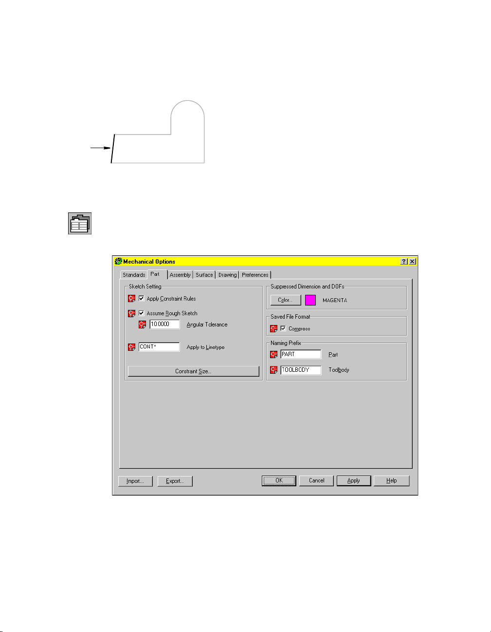
All lines were redrawn as horizontal or vertical except one. L1 remains angled
because the angle of the line exceeds the setting for angular tolerance. By
default, this rule makes a line horizontal or vertical if the angle is within 4
degrees of horizontal or vertical.
L1
You can modify this and other sketch tolerance settings to adjust the precision of your sketch analysis.
4 Change the angular tolerance setting.
Browser Click the Options button below the window.
5 In the Mechanical Options dialog box, choose the Part tab and change the
angular tolerance from 4 degrees to 10 degrees, the maximum value.
Choose OK.
54 | Chapter 6 Creating Parametric Sketches
Page 69

6 Reprofile the sketch, responding to the prompts.
Context Menu In the graphics area, right-click and choose Sketch Solving
➤ Profile.
NOTE You cannot use Single Profile to reprofile a sketch.
Select objects for sketch: Use a crossing window to specify the sketch
Select objects for sketch: Press ENTER
L1
If your sketch shows line L1 unchanged, the angle was greater than 10
degrees. You need to edit or redraw the shape and append the sketch.
NOTE When adding geometry or changing a sketch, you must append the
new geometry so that the sketch is reanalyzed and constraints are reapplied. See
chapter 7, “Constraining Sketches,” to append geometry to a sketch.
When L1 was made vertical, it required one less dimension or constraint to
fully solve the sketch. The following message is displayed on the command
line.
Solved underconstrained sketch requiring 4 dimensions or constraints.
Save your file.
You can adjust sketch rules that determine how precisely you need to draw.
For most sketching, you should use the default settings. However, you can
change the default settings as needed.
Creating Profile Sketches | 55
Page 70

Using Nested Loops
You can select more than one closed loop to create a profile sketch. A closed
loop must encompass the nested loops. They cannot overlap, intersect, or
touch. With nested loops you can easily create complex profile sketches.
To create a profile sketch using nested loops
AMNEW to create a new part definition.
1 Use
Context Menu In the graphics area, right-click and choose Part ➤ New
Part.
2 Accept the default part name on the command line.
The Browser now contains a third part.
3 Pan the drawing so you have room to create the next sketch.
Context Menu In the graphics area, right-click and choose Pan.
4 Create the following sketch using lines or polylines, and circles. Then, in the
graphics area, right-click and choose 2D Sketching ➤ Trim and follow the
prompts on the command line to remove the section from the smaller circle.
56 | Chapter 6 Creating Parametric Sketches
Page 71
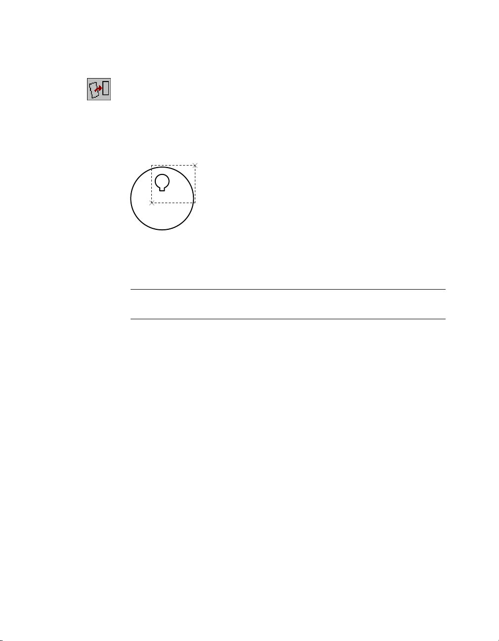
5 Profile the sketch, following the prompts to select the objects with a crossing
window.
Context Menu In the graphics area, right-click and choose Sketch Solving
➤ Profile.
Select objects for sketch: Specify a point to the right of the sketch (1)
Specify opposite corner: Specify a second point (2)
5 found
Select objects for sketch: Press
1
2
ENTER
Mechanical Desktop calculates the number of dimensions or constraints
required to fully constrain the profile.
Solved underconstrained sketch requiring 7 dimensions or constraints.
NOTE You may need more dimensions or constraints, depending on how you
created your sketch.
Save your file.
This simple cam illustrates how you can easily create complex shapes to
define parts and features. Experiment on your own to create profiles from
nested loops.
Creating Profile Sketches | 57
Page 72
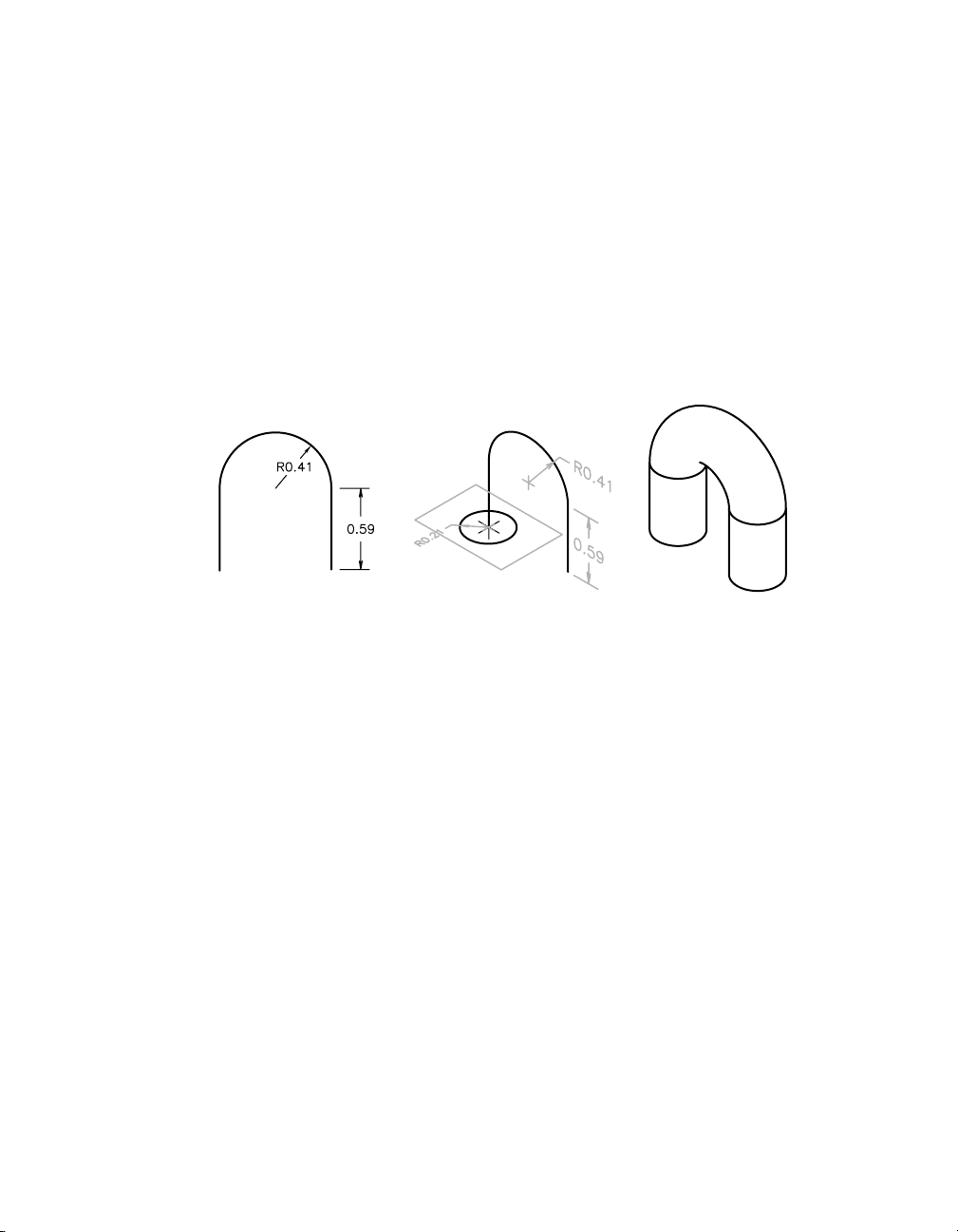
Creating Path Sketches
Path sketches can be both two dimensional and three dimensional. Like
open profile sketches, they can be open shapes. In this exercise, you create
only the path sketches, but not the profiles that would sweep along the
paths.
Creating 2D Path Sketches
A 2D path sketch serves as a trajectory for a swept feature. You create a swept
feature by defining a path and then a profile sketch of a cross section. Then,
you sweep the profile along the path.
The geometry for the 2D path must be created on the same plane.
swept featurepath sketch profile sketch
Valid geometry that can be used to create a 2D path includes
■ Lines
■ Arcs
■ Polylines
■ Ellipse segments
■ 2D splines
When you solve a 2D path sketch, you can automatically create a work plane
normal to the start point of the path. You use this work plane to create a profile sketch for the swept feature, and then constrain the profile sketch to the
start point of the path.
58 | Chapter 6 Creating Parametric Sketches
Page 73

To create a 2D path sketch
1 Create a new part definition.
Context Menu In the graphics area, right-click and choose Part ➤ New
Part.
2 Press ENTER on the command line to accept the default part name.
3 Pan the drawing so you have room to create the next sketch.
Context Menu In the graphics area, right-click and choose Pan.
4 Use
PLINE to draw the rough sketch as a continuous shape, responding to the
prompts to specify the points in the following illustration.
Context Menu In the graphics area, right-click and choose 2D Sketching
➤ Polyline.
Specify start point: Specify a point (1)
Current line-width is 0.0000
Specify next point or [Arc/Close/Halfwidth/Length/Undo/Width]:
Specify a second point (2)
Specify next point or [Arc/Close/Halfwidth/Length/Undo/Width]:
Enter a to create an arc segment
Specify endpoint of arc or
[Angle/CEnter/CLose/Direction/Halfwidth/Line/Radius/Second pt/Undo/Width]:
Specify a third point (3)
Specify endpoint of arc or
[Angle/CEnter/CLose/Direction/Halfwidth/Line/Radius/Second pt/Undo/Width]:
Enter l to create a line segment
Specify next point or [Arc/Close/Halfwidth/Length/Undo/Width]:
Specify a fourth point (4)
Specify next point or [Arc/Close/Halfwidth/Length/Undo/Width]: Press
ENTER
2
1
3
4
Make sure to switch between drawing lines and arcs at points (2) and (3).
Creating Path Sketches | 59
Page 74

5 Use AM2DPATH to convert the rough sketch to a path sketch, following the
prompts.
Context Menu In the graphics area, right-click and choose Sketch Solving
➤ 2D Path.
Select objects: Specify the polyline shape
Select objects: Press
ENTER
At the prompt for the start point of the path, you select the point where the
path begins. This determines the direction to sweep the profile of the cross
section.
Select start point of the path: Specify the start point (1)
1
You can also specify whether a work plane is created perpendicular to the
path. In this example, a work plane is not required.
Create a profile plane perpendicular to the path? [Yes/No] <Yes>: Enter n
NOTE If you choose to create a sketch to sweep along the path, Mechanical
Desktop can automatically place a work plane perpendicular to the path.
Press the F2 function key to activate the AutoCAD Text window. Examine the
prompts for the AM2DPATH command. The following line is displayed:
Solved underconstrained sketch requiring 3 dimensions or constraints.
The sketch analysis rules indicate that the path sketch needs three more
dimensions or constraints to fully define the sketch.
60 | Chapter 6 Creating Parametric Sketches
Page 75

A work point is automatically placed at the start point of the path. The
Browser displays both a 2DPath icon and a work point icon nested below the
part definition.
AMSHOWCON to display the existing constraints, responding to the
6 Use
prompt.
Context Menu In the graphics area, right-click and choose 2D
Constraints ➤ Show Constraints.
Enter an option [All/Select/Next/eXit] <eXit>: Enter a
The start point of the path is fixed. Both lines are vertical and are tangent to
the endpoints of the arc. The missing information is the length of each line and
the radius of the arc. Given these values, the sketch would be fully constrained.
Enter an option [All/Select/Next/eXit] <eXit>: Press
ENTER
Save your file.
Next, you create a three-dimensional path.
Creating Path Sketches | 61
Page 76

Creating 3D Path Sketches
3D path sketches are used to create
■ A 3D path from existing part edges
■ A helical path
■ The centerline of a 3D pipe
■ A 3D spline path
3D paths are used to create swept features that are not limited to one plane.
See chapter 8, “Creating Sketched Features,” to learn more about sweeping
features along a 3D path.
Open the file sketch2.dwg in the desktop\tutorial folder. The drawing contains
four part definitions and the geometry you need to create the 3D paths.
NOTE Back up the tutorial drawing files so you still have the original files if you
make a mistake. See “Backing up Tutorial Drawing Files” on page 40.
Creating a 3D Edge Path
A 3D edge path is used to create a path from existing part edges. After you
create the path, you can sweep a profile and use a Boolean operation to combine the feature with the existing part.
3D edge path and profile sketch 3D sweep along edge path
62 | Chapter 6 Creating Parametric Sketches
Page 77

Before you can work on a part, it must be active. Activate PART1_1, responding to the prompts.
Context Menu In the graphics area, right-click and choose Part ➤
Activate Part.
Select part to activate or [?] <PART1_1>: Enter PART1_1
PART1_1 is activated, and highlighted in the Browser.
Use Pan to center PART1_1 on your screen.
Context Menu In the graphics area, right-click and choose Pan.
PART1_1 contains an extruded part.
To create a 3D edge path
1 Use
AM3DPATH to define the 3D edge path, following the prompts.
Context Menu In the graphics area, right-click and choose Sketch Solving
➤ 3D Edge Path.
Select model edges (to add): Specify the first part edge (1)
Select model edges (to add): Specify the next edges in a clockwise sequence
Select model edges (to add): Specify the last edge (9)
Select model edges (to add): Press
ENTER
Specify start point: Specify start point (1)
Create workplane? [Yes/No] <Yes>: Press
ENTER
The command method you use determines the prompts that are displayed.
1
9
Creating Path Sketches | 63
Page 78

2 Continue on the command line to place the work plane.
Plane=Parametric
Select edge to align X axis or [Flip/Rotate/Origin] <accept>: Press
ENTER
The path is created, and a work point is located at the start point. A work
plane is placed normal to the start of the path so you can sketch the profile
for the sweep feature.
In the Browser, the new geometry is nested below the extrusion and fillets in
PART1_1.
Save your file.
64 | Chapter 6 Creating Parametric Sketches
Page 79

Creating a 3D Helical Path
p
p
A 3D helical path is used for a special type of swept feature. Helical sweeps
are used to create threads, springs, and coils. You create a 3D helical path
from an existing work axis, cylindrical face, or cylindrical edge.
3D path
rofile sketch
3D helical swee
When you create a 3D helical path, you can specify whether a work plane is
also created. The work plane can be normal to the path, at the center of the
path, or along the work axis. You use this work plane to draw the profile
sketch for the helical sweep.
Before you begin, activate PART2_1, responding to the prompts.
Context Menu In the graphics area, right-click and choose Part ➤
Activate Part.
Select part to activate or [?] <PART1_1>: Enter PART2_1
PART2_1 is highlighted in the Browser and on your screen.
Use Pan to center PART2_1 on your screen.
Context Menu In the graphics area, right-click and choose Pan.
PART2_1 contains a cylinder and a work axis.
work axis
Creating Path Sketches | 65
Page 80

To create a 3D helical path
AM3DPATH to define the 3D helical path, responding to the prompts.
3 Use
Context Menu In the graphics area, right-click and choose Sketch Solving
➤ 3D Helix Path.
Enter path type [Helical/Spline/Edge/Pipe] <Edge>: Enter h
Select work axis, circular edge, or circular face for helical center:
Select the work axis (1)
The command method you use determines the prompts that are displayed.
1
4 In the Helix dialog box, specify the following:
Type: Revolution and Height
Revolutions: Enter 8
Height: Enter 2
Diameter: Enter .5
Orientation: Counter-Clockwise
Choose OK.
NOTE The path is automatically constrained with the parameters defined in
the Helix dialog box. You can edit the path at any time with AMEDITFEAT.
66 | Chapter 6 Creating Parametric Sketches
Page 81
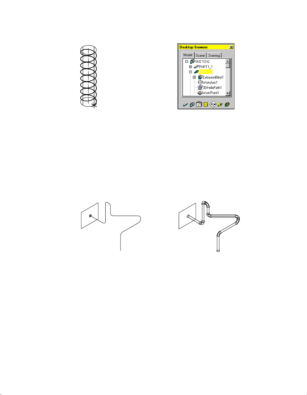
The 3D helix path is created. A work point is placed at the beginning of the path.
You can also specify that a work plane is placed normal to the start point of
the 3D path, at the center of the path, or along the work axis. This option
makes it easier for you to create the sketch geometry for the profile you sweep
along the path.
Save your file.
Creating a 3D Pipe Path
A 3D pipe path is used to sweep a feature along a three-dimensional path
containing line and arc segments or filleted polylines. You can modify each
of the control points and the angle of the segments in the 3D Pipe Path
dialog box.
3D pipe path and profile sketch 3D sweep along pipe path
Before you begin, activate PART3_1. This time use the Browser method to
activate the part.
Browser In the graphics area, double-click PART3_1.
PART3_1 is activated, and highlighted in the Browser.
Creating Path Sketches | 67
Page 82

Use Pan to center PART3_1 on your screen.
PART3_1 contains an unsolved sketch of line segments and arcs.
To create a 3D pipe path
AM3DPATH to define the 3D pipe path, responding to the prompts.
1 Use
Context Menu In the graphics area, right-click and choose Sketch Solving
➤ 3D Pipe Path.
Select polyline path source: Select the first line (1)
Select polyline path source: Select the remaining arcs and lines in sequence
Select polyline path source: Press ENTER
Specify start point: Specify a point near the start of the first line (1)
The command method you use determines the prompts that are displayed.
1
68 | Chapter 6 Creating Parametric Sketches
Page 83

2 In the 3D Pipe Path dialog box, examine the vertices and angles of the path.
Verify that Create Work Plane is selected.
NOTE Your numbers might not match the illustration above.
Choose OK to exit the dialog box.
3 Place the work plane, following the prompts.
Plane=Parametric
Select edge to align X axis or [Flip/Rotate/Origin] <accept>: Press
The Desktop Browser now contains a 3D Pipe icon, a work plane, and a work
point nested below the PART3_1 definition.
ENTER
Save your file.
Creating Path Sketches | 69
Page 84

Creating a 3D Spline Path
In this type of path, you sweep a feature along a 3D spline created with fit
points or control points. Working in one integrated dialog box, you can modify any fit point or control point in a 3D spline path, and you can convert fit
points to control points, and control points to fit points.
In this exercise, you work with a fit point spline.
3D spline path and profile sketch 3D sweep along spline path
Before you begin, activate PART4_1 from the Browser.
Browser In the graphics area, double-click PART4_1.
PART4_1 is highlighted in the Browser and on your screen.
Use Pan to center PART4_1 on your screen.
PART4_1 contains an unsolved spline sketch.
To create a 3D spline path
AM3DPATH to define the 3D spline path, responding to the prompts.
1 Use
Context Menu In the graphics area, right-click and choose Sketch Solving
➤ 3D Spline Path.
Select 3D spline path source: Specify the spline
Specify start point: Specify the start point
The command method you use determines the prompts that are displayed.
70 | Chapter 6 Creating Parametric Sketches
Page 85

2 In the 3D Spline Path dialog box, examine the vertices of the spline, and ver-
ify that Create Work Plane is selected.
NOTE Your numbers might not match the illustration above.
Choose OK to exit the dialog box.
3 Create the work plane, responding to the prompts.
Plane=Parametric
Select edge to align X axis or [Flip/Rotate/Origin] <accept>: Press ENTER
The path is created, and a work point is located at the start point. A work
plane is placed normal to the start of the path so you can begin to sketch the
profile for the sweep feature.
Save your file.
Creating a path sketch is similar to creating a profile sketch. The difference
between the two sketch types is their purpose.
■ Profile sketches provide a general way to create a variety of features.
■ Path sketches are used exclusively for creating trajectory paths for 2D and
3D swept features.
Creating Path Sketches | 71
Page 86
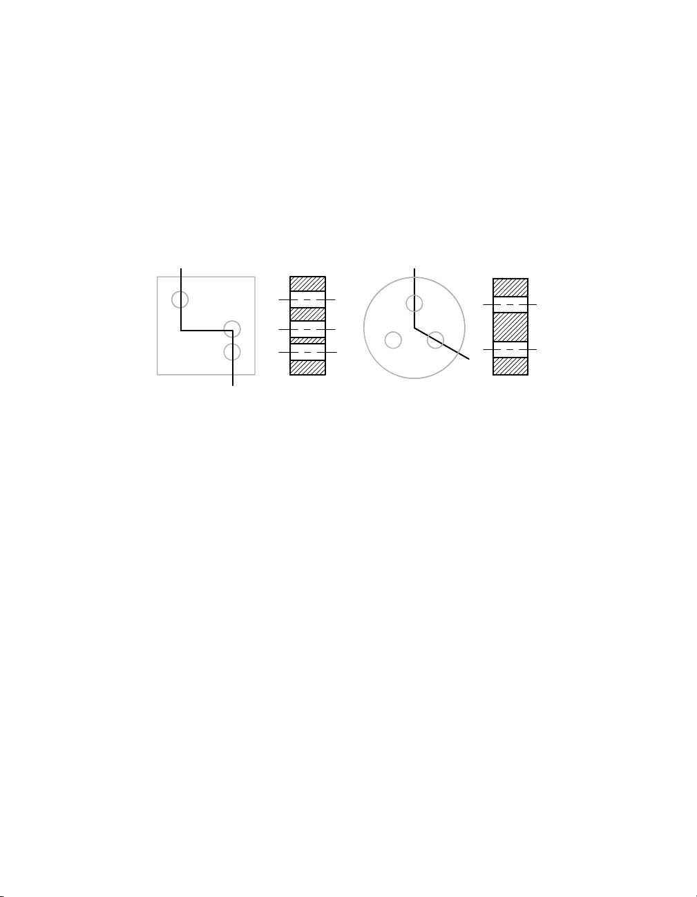
Creating Cut Line Sketches
When you create drawing views, you might want to depict a cut path across
a part for offset, cross-section views. After you have extruded or revolved a
profile sketch to create a feature, you can return to an original sketch and
draw the cut line across the features you want to include in the cross section.
There are two types of cut line sketches: offset and aligned. An offset cut line
sketch is a two-dimensional line constructed from orthogonal segments. An
aligned cut line sketch is a two-dimensional line constructed from nonorthogonal segments.
section viewoffset cut line section viewaligned cut line
Two general rules govern cut line sketches:
■ Only line and polyline segments are allowed.
■ The start and end points of the cut line must be outside the part.
These additional rules apply to cut line sketches:
■ The first and last line segments of an offset cut line must be parallel.
■ Offset cut line segments can change direction in 90-degree increments
only.
■ Only two line segments are allowed in an aligned cut line.
■ Line segments of aligned cut lines can change direction at any angle.
72 | Chapter 6 Creating Parametric Sketches
Page 87

In the following exercise, after you create a cut line sketch on these models,
the resulting cross-section drawing views can be generated in Drawing mode.
A cut line sketch is needed when you want to define a custom cross-section
view only, but not for a half or full cross-section view.
Open the file sketch3.dwg in the desktop\tutorial folder. The drawing contains
two parts.
NOTE Back up the tutorial drawing files so you still have the original files if you
make a mistake. See “Backing up Tutorial Drawing Files” on page 40.
Before you begin, click the plus signs in front of SKETCH3 and PART1_1 to
expand the Browser hierarchy.
Creating Cut Line Sketches | 73
Page 88

To create an offset cut line sketch
PLINE to sketch through the center of the holes on the square part.
1 Use
Context Menu In the graphics area, right-click and choose 2D Sketching
➤ Polyline.
Next, analyze the cut line sketch according to internal sketching rules.
2 Use
AMCUTLINE to solve the cut line, responding to the prompts.
Context Menu In the graphics area, right-click and choose Sketch Solving
➤ Cut Line.
Select objects to define the section cutting line: Select the polyline (1)
Select objects to define the section cutting line: Press
1
ENTER
A new icon called CutLine1 is added to the PART1_1 hierarchy in the
Browser.
Save your file.
74 | Chapter 6 Creating Parametric Sketches
Page 89
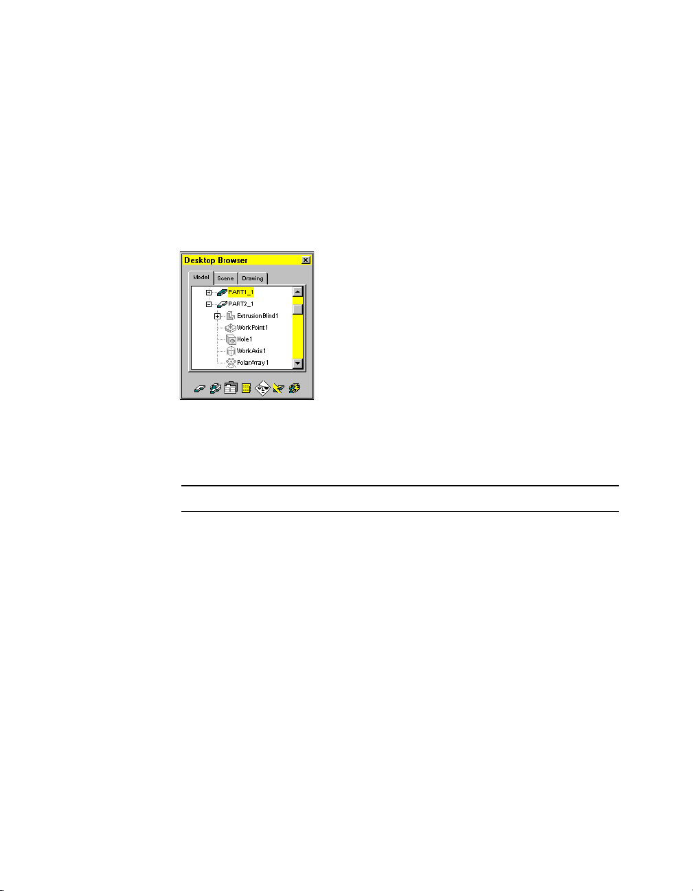
As with the other sketches you created, a message tells you how many dimensions and constraints are needed to fully solve the sketch. In this case, you
need five dimensions or constraints to complete the definition of the sketch:
three to define the shape of the sketch, and two to constrain it to the part.
When you create a cross-section drawing view, this sketch defines the path
of the cut plane. If you change the size of the part or holes, or their placement, the cut line is updated to reflect the new values.
For the next exercise, you use the circular part. In the Browser, click the
minus sign in from of PART1_1 to collapse the part hierarchy. Then click the
plus sign in front of PART2_1 to expand the circular part hierarchy.
Before you begin, you need to activate the circular part.
Browser Double-click PART2_1.
PART2_1 is activated, and highlighted in the Browser and on your screen.
NOTE Before you can work on a part, it must be active.
Creating Cut Line Sketches | 75
Page 90

To create an aligned cut line sketch
PLINE to sketch through the centers of two of the holes on the circular
1 Use
part.
Context Menu In the graphics area, right-click and choose 2D Sketching
➤ Polyline.
2 Define a cut line on your sketch, responding to the prompts.
Context Menu In the graphics area, right-click and choose Sketch Solving
➤ Cut Line.
Select objects to define the section cutting line: Select the polyline (2)
Select objects to define the section cutting line: Press
2
ENTER
A message states that you need five dimensions or constraints to fully solve
this sketch.
3 In the Browser, the new CutLine1 icon is part of the PART2_1 hierarchy.
Save your file.
76 | Chapter 6 Creating Parametric Sketches
Page 91
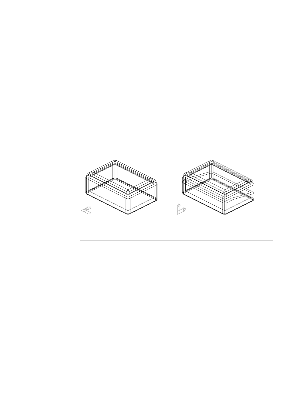
Creating Split Line Sketches
A molded part or casting usually requires two or more shapes to define the
part. To make a mold or a cast, you create the shape of your part and then
apply a split line to split the part into two or more pieces. You may also need
to apply a small draft angle to the faces of your part so that your part can be
easily removed from the mold.
Split lines can be as simple as a planar intersection with your part, or as complex as a 3D polyline, or spline, along planar or curved faces.
You can also split parts using either
■ A selected planar face or a work plane
■ A sketch projected onto a selected set of faces
In this exercise, you create a split line to split a shelled part into two separate
parts.
shelled part split part
Open the file sketch4.dwg in the desktop\tutorial folder.
NOTE Back up the tutorial drawing files so you still have the original files if you
make a mistake. See “Backing up Tutorial Drawing Files” on page 40.
The drawing file contains a simple shelled box. Two viewports have been
defined: the right side of the part, and an isometric view. You’ll define a new
sketch plane in the right viewport and sketch a split line in the left viewport.
Creating Split Line Sketches | 77
Page 92

To create a split line
1 Expand the Browser hierarchy of SKETCH4 and PART1_1.
The part consists of an extrusion, three fillets, and a shell feature. Next, you
create a sketch plane on the outside right face of the part.
2 In the right viewport, define a new sketch plane, responding to the prompts.
Context Menu In the graphics area, right-click and choose New Sketch
Plane.
Select work plane, planar face or [worldXy/worldYz/worldZx/Ucs]:
Specify the outside right face of the part (1)
Enter an option [Accept/Next] <Accept>: Press
ENTER
Plane = Parametric
Select edge to align X axis [Flip/Rotate/Origin] <accept>: Press
ENTER
Next, create a sketch and convert it to a split line.
78 | Chapter 6 Creating Parametric Sketches
1
Page 93

3 In the left viewport, use PLINE to sketch the split line.
Context Menu In the graphics area, right-click and choose 2D Sketching
➤ Polyline.
AMSPLITLINE to create a split line from your sketch, responding to the
4 Use
prompts.
Context Menu In the graphics area, right-click and choose Sketch Solving
➤ Split Line.
Select objects for sketch: Select the polyline
Select objects for sketch: 1 found
Select objects for sketch: Press
ENTER
Select edge to include in split line or press <ENTER> to accept: Press ENTER
Mechanical Desktop solves the sketch and displays the number of constraints
required to fully constrain it.
Solved underconstrained sketch requiring 5 dimensions or constraints.
5 Look at the Browser. SplitLine1 is now nested under the part definition.
Save your file.
Creating Split Line Sketches | 79
Page 94

Creating Break Line Sketches
When you want to document complex assemblies, it is not always easy to display parts and subassemblies that are hidden by other parts in your drawing
views. By creating a break line sketch, you can specify what part of your
model will be cut away in a breakout drawing view so that you can illustrate
the parts behind it.
break line path breakout drawing view
Open the file sketch4a.dwg in the desktop\tutorial folder.
NOTE Back up the tutorial drawing files so you still have the original files if you
make a mistake. See “Backing up Tutorial Drawing Files” on page 40.
The drawing file contains a simple part. An unsolved sketch lies on a work
plane. You create a break line from this sketch.
80 | Chapter 6 Creating Parametric Sketches
Page 95

To create a break line
AMBREAKLINE to define the break line sketch, following the prompts.
1 Use
Context Menu In the graphics area, right-click and choose Sketch Solving
➤ Break Line.
Select objects for sketch: Specify the sketch (1)
Select objects for sketch: Press
ENTER
1
The break line is created. The Browser contains a break line icon nested below
the work plane.
Save your file.
Now that you have learned the basics of creating sketches, you are ready to
constrain them by adding geometric and parametric dimension constraints.
Creating Break Line Sketches | 81
Page 96

82
Page 97

Constraining Sketches
In This Chapter
7
When you solve a sketch in Autodesk® Mechanical
®
Desktop
accordance with internal rules. To fully constrain the
sketch, you apply the remaining parametric dimensions
and geometric constraints that are necessary to meet
your design goals.
Any time you modify a sketch, the parametric geometry
retains the relationships among design elements.
To reduce the number of constraints required to fully
constrain a sketch, you can use construction geometry.
Construction geometry becomes part of the sketch, but
is ignored when the sketch is used to create a feature.
, geometric constraints are applied in
Creating a strategy for
■
constraining and dimensioning
■ Defining sketch shape and size
with dimensions and geometric
constraints
■ Using construction lines, arcs,
and circles to create and control
sketches
■ Modifying a design
■ Re-creating a constrained sketch
In the next chapter, you learn to add sketched features
to your constrained sketches.
83
Page 98

Key Terms
Te r m Definition
2D constraint Defines how a sketch can change shape or size. Geometric constraints control the
degree of freedom In part modeling, determines how a geometric object such as a line, arc, or circle
dimensional constraint Parametric dimension that controls the size of a sketch. When changed, the
geometric constraint Controls the shape and relationships among geometric elements in a sketch.
parametrics A solution method that uses the values of part parameters to determine the
shape and relationships among sketch lines and arcs. Dimensional constraints
control the size of sketch geometry.
can change shape or size. For example, a circle has two degrees of freedom,
center and radius. When these values are known, degrees of freedom are said to
be eliminated.
sketch resizes. May be expressed as a constant value, a variable in an equation, a
variable in a table, or in global parameter files.
geometric configuration of the part.
84 | Chapter 7 Constraining Sketches
Page 99

Basic Concepts of Creating Constraints
A sketch needs geometric and dimensional constraints to define its shape and
size. These constraints reduce the degrees of freedom among the elements of
a sketch and control every aspect of its final shape.
When you solve a sketch, Mechanical Desktop applies some geometric
constraints. In general, use the automatically applied constraints to stabilize
the sketch shape.
Depending upon how accurately you sketch, you may need to add one or
more constraints to fully solve a sketch. You can also add construction
geometry to your sketch to reduce the number of additional constraints
required. After you add further constraints, you might need to delete some
of the applied constraints.
In most cases, you need to fully constrain sketches before you use them to
create the features that define a part. As you gain experience, you will be able
to determine which constraints control the sketch shape according to your
design requirements.
Basic Concepts of Creating Constraints | 85
Page 100

Constraining Tips
Tip Explanation
Determine sketch
dependencies
Analyze automatically
applied constraints
Use only needed
constraints
Stabilize shape
before size
Dimension large
before small
Use both geometric
constraints and
dimensions
Analyze the design to determine how sketch elements
interrelate; then decide which geometric constraints are
needed.
Determine the degrees of freedom not resolved by automatic
constraints. Decide if any automatic constraints need to be
deleted in order to constrain elements as you require.
Replace constraints as needed to define shape. Because
constraints often solve more than one degree of freedom, use
fewer constraints than degrees of freedom.
If you apply geometric constraints before dimensions, your
sketch shape is less likely to become distorted.
To minimize distortion, define larger elements that have an
overall bearing on the sketch size. Dimensioning small elements
first may restrict overall size. Delete or undo a dimension if the
sketch shape is distorted.
Some constraint combinations may distort unconstrained
portions of the sketch. If so, delete the last constraint and
consider using a dimension or a different constraint
combination.
Constraining Sketches
Constraining a sketch defines how a sketch can change shape or size. In addition to the inferences by the software, you often need additional dimensions
or constraints.
Constraints may be fixed or variable, but they always prevent unwanted
changes to a feature as you make modifications.
86 | Chapter 7 Constraining Sketches
 Loading...