

Page 1

AutoCAD Architecture 2008
Getting Started with
AutoCAD Architecture
March 2007
Page 2

All Rights Reserved
This publication, or parts thereof, may not be reproduced in any form, by any method, for any purpose.
AUTODESK, INC., MAKES NO WARRANTY, EITHER EXPRESS OR IMPLIED, INCLUDING BUT NOT LIMITED TO ANY
IMPLIED WARRANTIES OF MERCHANTABILITY OR FITNESS FOR A PARTICULAR PURPOSE REGARDING THESE
MATERIALS, AND MAKES SUCH MATERIALS AVAILABLE SOLELY ON AN "AS-IS" BASIS.
IN NO EVENT SHALL AUTODESK, INC., BE LIABLE TO ANYONE FOR SPECIAL, COLLATERAL, INCIDENTAL, OR
CONSEQUENTIAL DAMAGES IN CONNECTION WITH OR ARISING OUT OF PURCHASE OR USE OF THESE MATERIALS.
THE SOLE AND EXCLUSIVE LIABILITY TO AUTODESK, INC., REGARDLESS OF THE FORM OF ACTION, SHALL NOT
EXCEED THE PURCHASE PRICE OF THE MATERIALS DESCRIBED HEREIN.
Autodesk, Inc., reserves the right to revise and improve its products as it sees fit. This publication describes the state of the product at the time
of publication, and may not reflect the product at all times in the future.
Autodesk Trademarks
Copyright© 2007 Autodesk, Inc.
The following are registered trademarks of Autodesk, Inc., in the USA and/or other countries: AutoCAD, Autodesk, and Autodesk (logo).
Third Party Trademarks
All other brand names, product names or trademarks belong to their respective holders.
Third Party Software Program Credits
ACIS Copyright© 1989-2001 Spatial Corp.
Copyright© 1997 Microsoft Corporation. All rights reserved.
International CorrectSpell™ Spelling Correction System© 1995 by Lernout & Hauspie Speech Products, N.V. All rights reserved.
InstallShield™ 3.0. Copyright© 1997 InstallShield Software Corporation. All rights reserved.
PANTONE® and other Pantone, Inc. trademarks are the property of Pantone, Inc.© Pantone, Inc., 2002
Portions Copyright© 2002 Autodesk, Inc.All rights reserved.
Portions of this software are based on the work of the Independent JPEG Group.
Typefaces from the Bitstream® typeface library copyright 1992.
Typefaces from Payne Loving Trust© 1996. All rights reserved.
Printed manual and help produced with Idiom WorldServer™.
GOVERNMENT USE
Use, duplication, or disclosure by the U.S. Government is subject to restrictions as set forth in FAR 12.212 (Commercial Computer
Software-Restricted Rights) and DFAR 227.7202 (Rights in Technical Data and Computer Software), as applicable.
1 2 3 4 5 6 7 8 9 10
Page 3

Contents
Chapter 1 Getting Started . . . . . . . . . . . . . . . . . . . . . . . . . . . . . . . . . . . . . . . . . 1
Using this Guide . . . . . . . . . . . . . . . . . . . . . . . . . . . . . . . . . . . . . . . . . . . . . . . . . . . 2
Opening the Project . . . . . . . . . . . . . . . . . . . . . . . . . . . . . . . . . . . . . . . . . . . . . . . . . 2
Managing Your Drawings . . . . . . . . . . . . . . . . . . . . . . . . . . . . . . . . . . . . . . . . . . . . . . 3
Creating Spaces to Calculate Floor Plan Area . . . . . . . . . . . . . . . . . . . . . . . . . . . . . . . . . . . . 6
Creating Color-Filled Presentation Plans . . . . . . . . . . . . . . . . . . . . . . . . . . . . . . . . . . . . . . 13
Laying Out a Floor Plan . . . . . . . . . . . . . . . . . . . . . . . . . . . . . . . . . . . . . . . . . . . . . . . 14
Creating Schedules . . . . . . . . . . . . . . . . . . . . . . . . . . . . . . . . . . . . . . . . . . . . . . . . . 23
Making Floor Plan Revisions . . . . . . . . . . . . . . . . . . . . . . . . . . . . . . . . . . . . . . . . . . . . 27
Creating a Section . . . . . . . . . . . . . . . . . . . . . . . . . . . . . . . . . . . . . . . . . . . . . . . . . 31
Detailing Your Design . . . . . . . . . . . . . . . . . . . . . . . . . . . . . . . . . . . . . . . . . . . . . . . 33
Index . . . . . . . . . . . . . . . . . . . . . . . . . . . . . . . . . . . . . . . . . . . . . . . . . . . . . 41
Contents | iii
Page 4

iv | Contents
Page 5

Getting Started
Welcome to AutoCAD® Architecture 2008! In this short tutorial, you learn how
to use the features of AutoCAD Architecture to design and document a small office
building. Working from a two-dimensional AutoCAD floor plan sketch, you
quickly create a presentation plan, a floor plan layout, door and window schedules,
a section, and a detail, all within a coordinated set of drawings.
1
You see how a more powerful AutoCAD®, with features and content specialized
for use by architects, can help you increase productivity. When you design in
AutoCAD Architecture, you use objects that represent real-world components,
such as walls, doors, and windows. These objects contain information that allows
them to function like the real-world components that they represent and to relate
intelligently to each other.
In addition to your main design tasks, many background tasks, such as layering
and scaling, are automated as you design and document your drawing set. A
simple tool, called the Project Navigator, allows you to easily work with all the
drawings in a project, eliminating the need to set up and maintain a complex file
structure.
1
Page 6

Using this Guide
To complete the tutorial in this guide, you must have AutoCAD Architecture installed on your system. As you progress
through the tutorial exercises, you access tutorial drawings and other content from the default installation directories.
If you cannot locate a file in the location that this guide suggests, it may be installed in a different location. Contact
your CAD Manager for more information.
Imperial and Metric Convention
The exercises in this guide contain both imperial and metric values. This means that when you see an imperial value,
a metric value is displayed in square brackets next to it.
For example: Add a 6' X 6' [1800 mm X 1800 mm] window centered in the top wall of the stairway.
All audiences using imperial measurements should use the imperial values only. All audiences using metric measurements
should use the metric values in brackets only. Note that the imperial and metric values are not direct conversions, but
appropriate values for completing either the imperial or metric project.
Opening the Project
In this exercise, you start AutoCAD Architecture, learn how to access AutoCAD Architecture learning resources, and
open the project that contains the drawings you use to complete the tutorial. In AutoCAD Architecture, you use projects
to store and manage all the drawings that you create to design and document your projects.
1 Start AutoCAD Architecture.
2 If this is the first time you have opened AutoCAD Architecture, a Welcome screen displays.
3 On the right side of the screen, under Essential Task Movies, click each title to view 2 minute long movies
that present the concepts you need to know to perform common design and documentation tasks in
AutoCAD Architecture.
The movies match the exercises in this guide, so you can benefit from both conceptual and hands-on
learning.
4 On the left side of the screen, explore the additional learning resources available to you:
■ Click User Interface Overview to interactively explore the AutoCAD Architecture user interface.
■ Click Learning Resources to access customized learning paths for different types of users, including
new and upgrading users.
■ Click New Features Workshop to view short animations that describe the new features in this, and
recent releases of AutoCAD Architecture.
■ Click AutoCAD
design and documentation tasks using the features and workflow of AutoCAD Architecture.
5 After you view the movies and other learning resources, click Next to display the Workspaces screen.
2 | Chapter 1 Getting Started
®
to AutoCAD® Architecture Task Comparison to learn how to accomplish typical
Page 7

On this screen, you can choose the workspace that you use to begin your project. Each AutoCAD Architecture
workspace includes the specific user interface components that you use in the appropriate phase of your
project. For example, the Design workspace contains all the basic tools that you need to create building
components in your design drawings.
After you close this screen, a Workspaces toolbar, located under the drop-down menus at the top of the
screen, lets you switch between workspaces.
6 In the top box on the left side of the Workspaces screen, select Design.
7 If you do not want the Welcome and Workspaces screens to display each time you start AutoCAD
Architecture, select Don’t show me this again.
8 Click OK.
9 Open the tutorial project:
■ On the Navigation toolbar, click (Project Browser).
You use the Project Browser to create, copy, and switch between projects.
■ In the left pane, click , and scroll up to view the current file path and folder.
By default, the path and folder is C:\My Documents\Autodesk\My Projects. This is where the project
file that you open and use for this tutorial is located.
■ In the left pane of the Project Browser, double-click the project, Getting_Started_I [Getting_Started_M].
The project displays in bold type to indicate it is the current project. The right pane of the Project
Browser displays the project bulletin board, which can be used to communicate information about
the current project.
■ Click Close.
Two important workspace features display: a Getting_Started project tool palette and the Project
Navigator.
The Getting_Started project tool palette contains all the AutoCAD Architecture tools that you need to
complete the exercises in this guide. Tools are objects that you use to draw in AutoCAD Architecture,
and they are arranged on tabbed palettes. The tool represents the real-world object that you want to
add to your drawing.
Using the Project Navigator, you create, access, and organize drawings in the current project within
the software environment.
Managing Your Drawings
In this exercise, you learn how AutoCAD Architecture project drawings are organized and managed. The Drawing
Management feature in AutoCAD Architecture lets you distribute your building geometry amongst a number of drawing
files and manage them with the Project Navigator, where in the past, you may have used Microsoft® Windows® Explorer
and the AutoCAD Xref Manager.
To store and manage these drawings with this feature, you first create a project. In the project, you create the basic
levels (floors) and divisions (wings) of the building model to create a matrix of locations where you can assign the
drawings that contain the geometry of your model.
Using enhanced AutoCAD Xref technology, drawings that contain the building geometry can then be referenced
together, and views of the building can be created and referenced onto plotting sheets. Depending on whether they
contain building geometry, assemble views of the building, or contain plotting sheets, project drawings are classified
within projects as constructs, elements, views, and sheets.
1 On the right side of the screen, view the tabs on the Project Navigator.
Managing Your Drawings | 3
Page 8

The 4 tabs on the side of the Project Navigator let you create, access, and organize the drawings in the
current project.
2 If it does not already display, click the Project tab.
The Project tab reports information that has already been added to the project: the project name and
number, and the levels and divisions that it contains. Levels are the floors of the building, and divisions
are wings or horizontal segments of the building. As you create your design drawings in this tutorial, you
will assign them a location on a building level. This Getting Started Project contains 5 levels and, because
it does not feature wings, a single default division.
3 Click the Constructs tab.
This tab organizes the drawings that create the geometry of your building. These drawings are classified as
constructs or elements.
Constructs are the main building blocks of your design. They define unique portions of the building, and
are assigned to a location (level and division) within it.
Although this Getting Started project is unfinished, a few constructs reside in the project: 2 floor slabs, an
elevator shaft, and an 05 floor. You will create constructs for floors 1-4 of the building.
In contrast, elements contain collections of geometry that can be used repeatedly in different design
drawings, such as a drawing of a service core that would be referenced onto multiple floors of a building.
In the AutoCAD Architecture project workflow, elements are referenced into constructs.
In this project, 2 typical restroom elements are provided. You will place these layouts on floors 1-4 of the
building by referencing them into each floor construct.
4 Click the Views tab.
4 | Chapter 1 Getting Started
Page 9
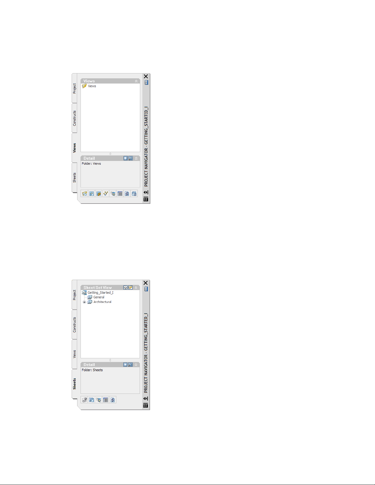
The Views tab organizes view drawings in which constructs and elements are referenced to provide specific
views of a building. Views allow you to tell AutoCAD Architecture in architectural terms what types of
drawings you want to assemble, such as first floor plans, second floor framing plans, or building sections.
Views may contain any number of constructs, which in turn, may reference elements. After you create
views, you can organize them on sheets.
No view drawings have been created in the Getting Started project.
5 Click the Sheets tab.
The Sheets tab organizes a set of project drawing sheets that you can plot or electronically publish. Sheet
drawings contain paperspace layouts that comprise the sheet layout. You reference model space views from
view drawings onto sheets to create sheet views.
If you are familiar with the AutoCAD Sheet Set Manager, the Sheets tab should also look familiar.
Since sheets contain views (which reference constructs) and elements, any changes to the design in the
constructs or elements can be easily updated in the views and sheets, by reloading the externally referenced
drawings.
Now that you have an overview of how your drawings are organized and managed in AutoCAD Architecture,
proceed to the next exercise to start designing.
Managing Your Drawings | 5
Page 10
Creating Spaces to Calculate Floor Plan Area
In this exercise, you use the automated space planning tools in AutoCAD Architecture to calculate area on a preliminary
floor plan. You use the linework in a 2D floor plan sketch created in AutoCAD to quickly generate 2D spaces complete
with tags that report each room area. After you create the spaces, you place a room schedule that automatically reads
the area information from the space tags, and reports it in the schedule table.
When the schedule is complete, you use the editing grips available on AutoCAD Architecture objects to change the
dimensions of a space on the floor plan. You watch how the space tag automatically reports the new room area, and
with the click of a button, you update the schedule to include the new area.
1 Open an AutoCAD drawing that contains the 2D floor plan sketch:
■ Click File menu ➤ Open.
■ Navigate to C:\My Documents\Autodesk\My Projects\Getting_Started_I [Getting_Started_M].
■ Select 01 Spaces Layout.dwg, and click Open.
The sketch, complete with delineated rooms for the space plan layout, displays. Although the sketch is
located in the project, it is not a project drawing (construct, element, view, or sheet). You must save the
sketch drawing to the project as a construct before you create the space plan.
2 Save the sketch to the project as a construct:
■ With 01 Spaces Layout open, on the Project Navigator, click the Constructs tab.
■ Right-click the Constructs folder, and click Save Current Drawing as Construct.
■ On the Add Construct worksheet, click the Name field, and enter 01 Space Plan.
6 | Chapter 1 Getting Started
Page 11

■ Under Assignments, for Level 1, select Division 1.
This setting assigns the 01 Space Plan to the first floor (level) of the building, in division 1 of the
building. By default, each building has a single division. Because this building does not have multiple
wings or other horizontal segments, it contains only the single default division.
■ Click OK.
Notice the open drawing has been renamed 01 Space Plan, and displays in the Constructs folder on
the Project Navigator.
Next, access a space tool, and set the tool properties so that the spaces you create are 2D and tagged as they
are created. The tools in AutoCAD Architecture streamline object creation by allowing you to specify
common options before you create the object.
3 On the Getting_Started tool palette that displays on the side of your screen, click the General Space tool.
If the tool is not visible, use the scroll bar on side of the palette to locate it.
4 Specify the Space tool properties:
■ On the Properties palette, under General, for Style, verify that Standard is selected.
■ For Tag, select Aec7_Space_Tag [M_Aec7_Space_Tag].
■ For Create type, select Generate.
■ For Associative, select No.
■ Under Generate Space, for Filter boundary set, select All linework.
■ Under Component Dimensions, for Geometry Type, select 2D.
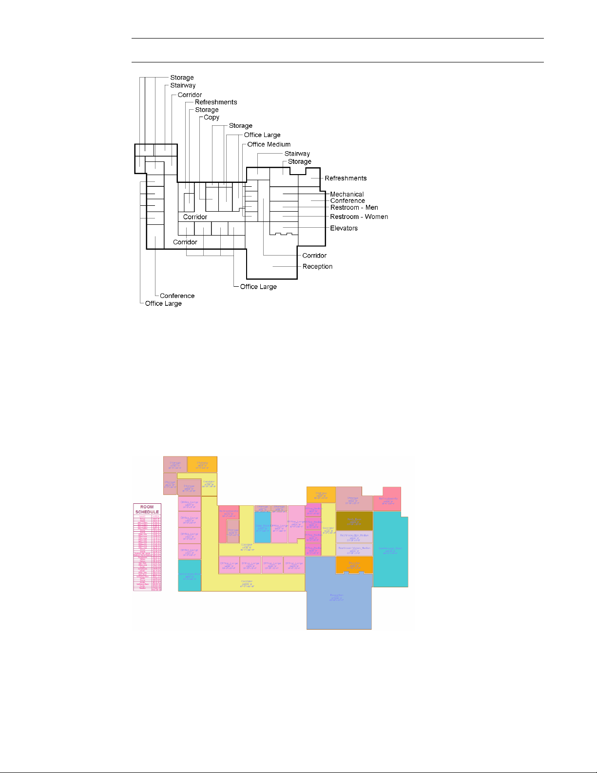
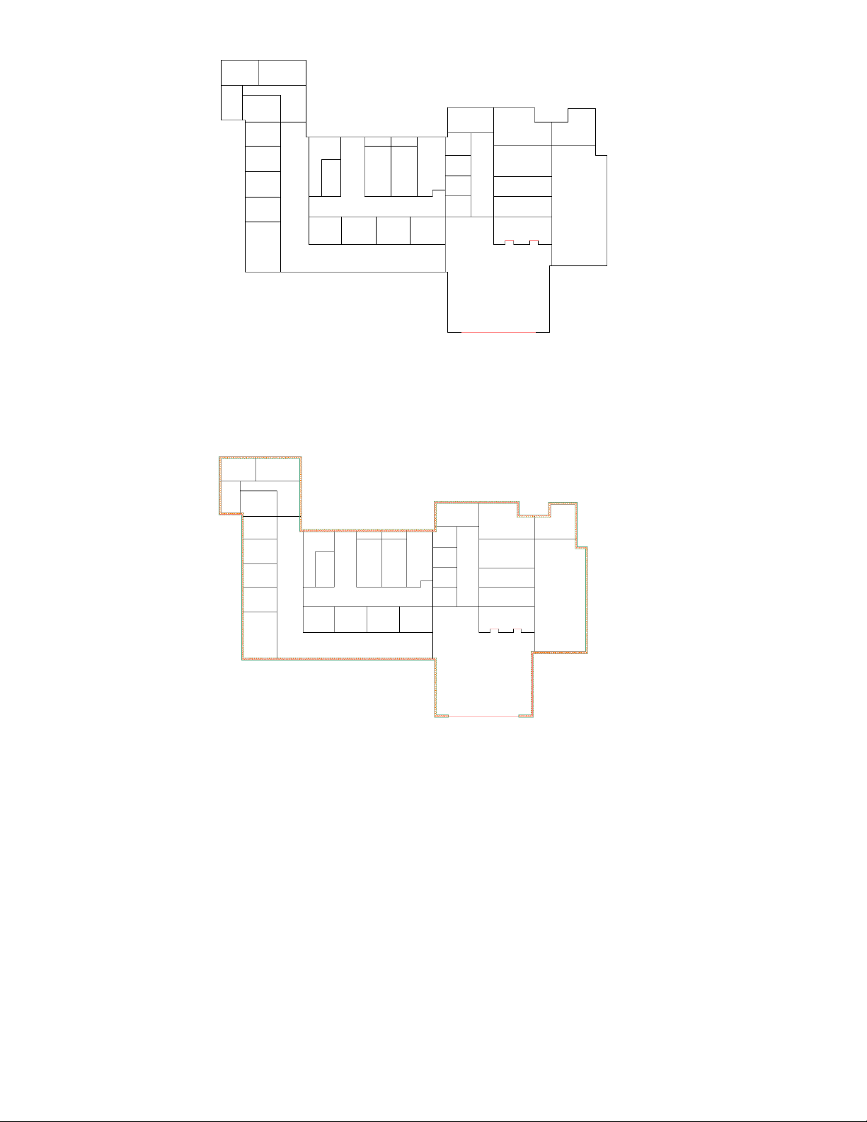
5 Without clicking inside a room, move the cursor into each room on the plan.
As you move the cursor into a room, the space object automatically detects the linework room boundary.
The boundary of the space that you can generate from the room linework displays in red.
6 Click in the large room on the bottom of the plan.
Creating Spaces to Calculate Floor Plan Area | 7
Page 12

A tagged space is created.
7 Autogenerate the remaining spaces on the plan:
■ Right-click in the drawing, and click Generate all.
Tagged spaces are created in the remaining rooms.
■ Press ESC to end the Space command.
8 Reposition 1 of the tags in the upper-left space:
■ Zoom to the 5 spaces in the upper-left corner of the floor plan.
■ If necessary, on the application status bar, click OSNAP to turn it off, as shown.
■ Select the tag that overlaps the 2 spaces on the lower-left.
8 | Chapter 1 Getting Started
Page 13
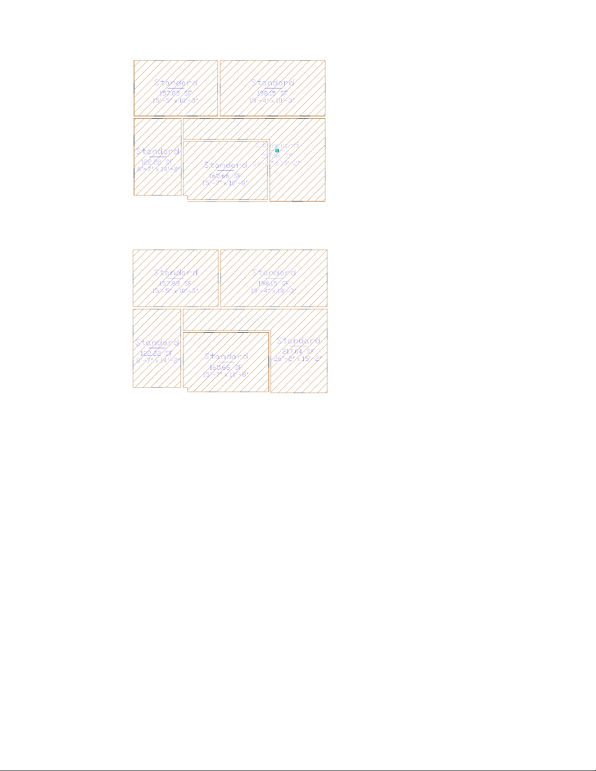
A light blue Location grip displays on the tag.
■ Select and move the Location grip to reposition the tag centrally on the space.
■ Press ESC to hide the grip.
9 If necessary, reposition the tags in the other spaces on the plan.
The space tags on the floor plan report that all the rooms are the same type of space. Next, learn how to
use the different space tools to create space objects for other room types on the plan.
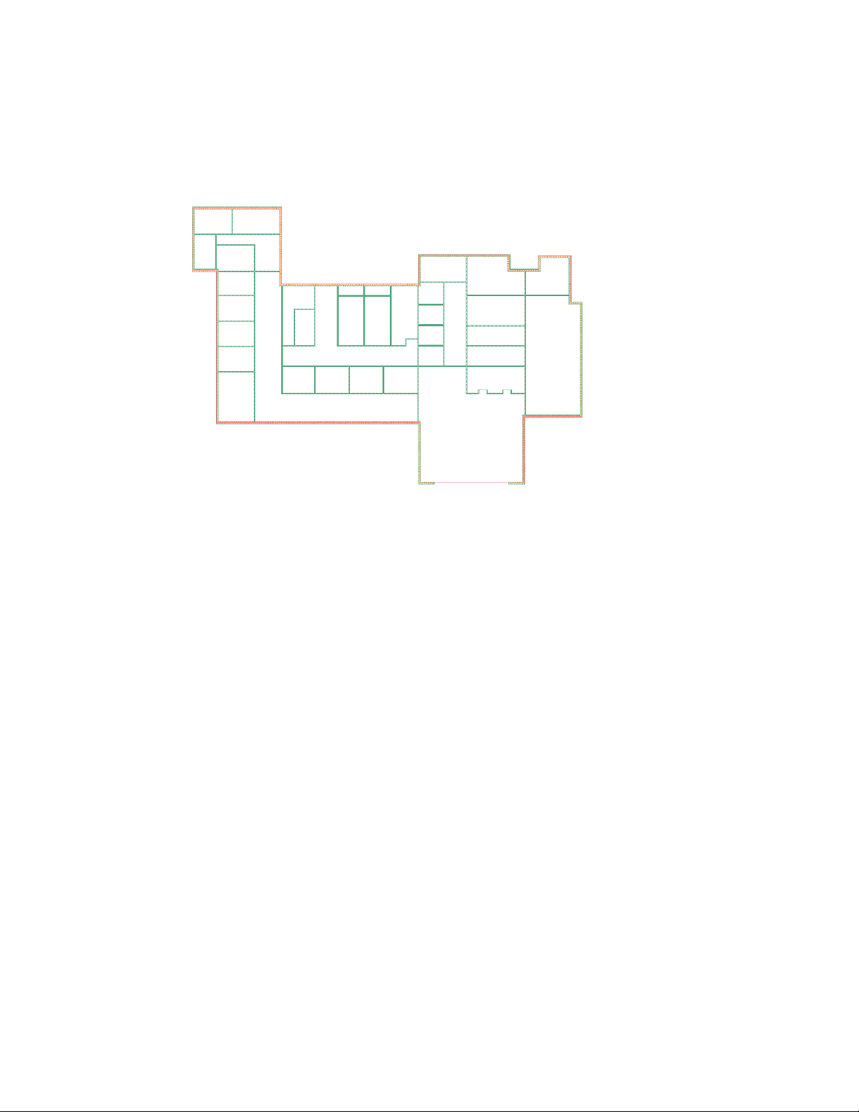
10 Redefine the spaces on the plan:
■ On the Getting_Started tool palette, right-click the Corridor tool, and click Apply Tool Properties
to ➤ Space.
■ Select the 4 corridors on the floor plan, as shown.
Creating Spaces to Calculate Floor Plan Area | 9
Page 14
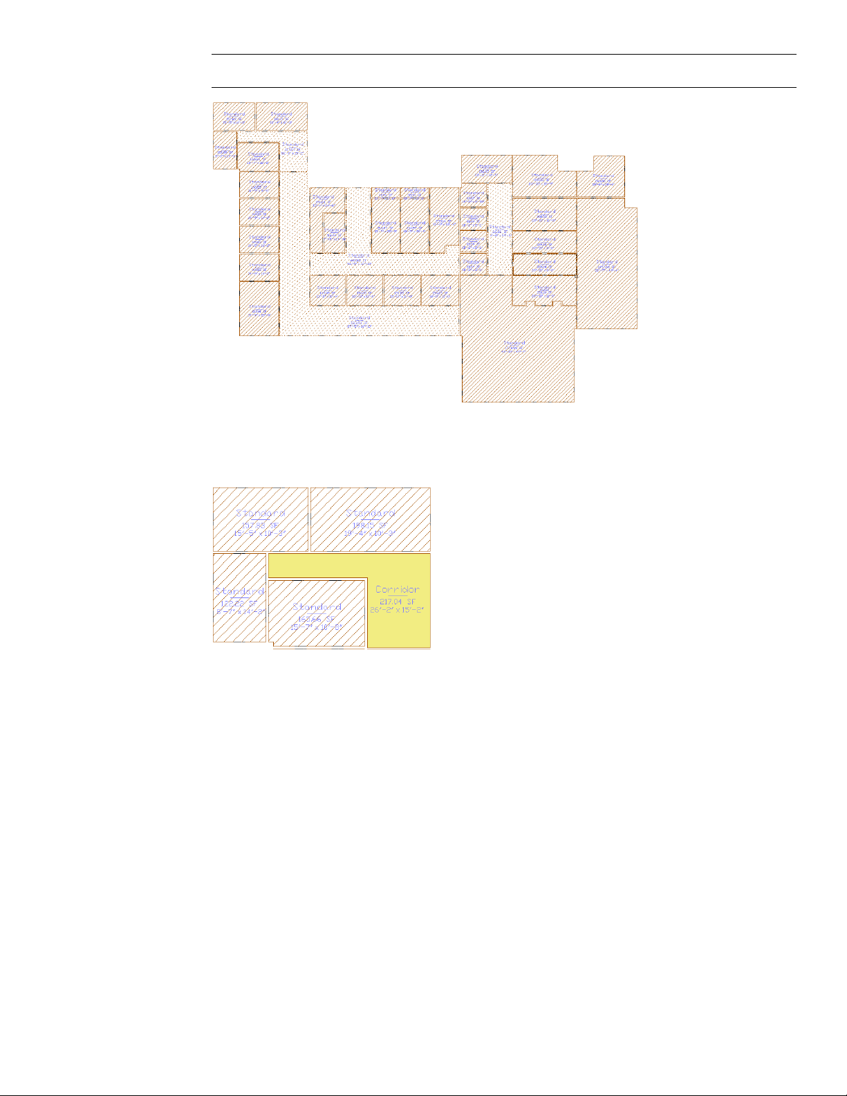
TIP Make sure you select the space and not the tag.
■ Press ENTER, and press ESC.
The space tag now identifies each selected space as a corridor, and the space displays with a colored
fill.
■ Use the other space tools on the Getting_Started tool palette that correspond to the names in the plan
shown below to redefine the remaining spaces on the plan. When you finish, all spaces on the plan
will display with colored fills.
10 | Chapter 1 Getting Started
Page 15
IMPORTANT Press ESC after creating each space type to end the previous space command.
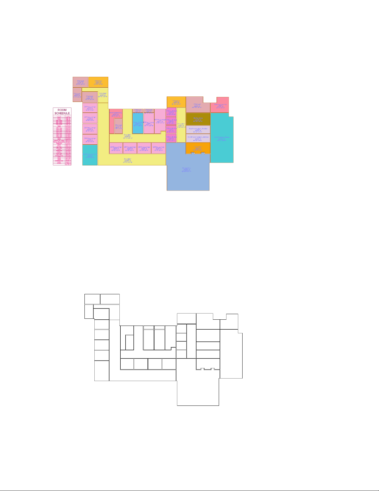
11 Create a preliminary room schedule that reports the name and area of each room:
■ On the Getting_Started tool palette, click the Room Area Schedule tool.
■ On the command line, enter all, and press ENTER twice.
■ Move the cursor to the left of the floor plan until the bottom of the schedule table aligns with the
bottom conference room wall, and click to place the upper-left corner of the schedule.
■ Press ENTER to place the bottom right corner of the schedule.
The schedule uses the space tags to read the information, called property set data, that is attached to
the spaces, and reports it in the schedule table.
Creating Spaces to Calculate Floor Plan Area | 11
Page 16
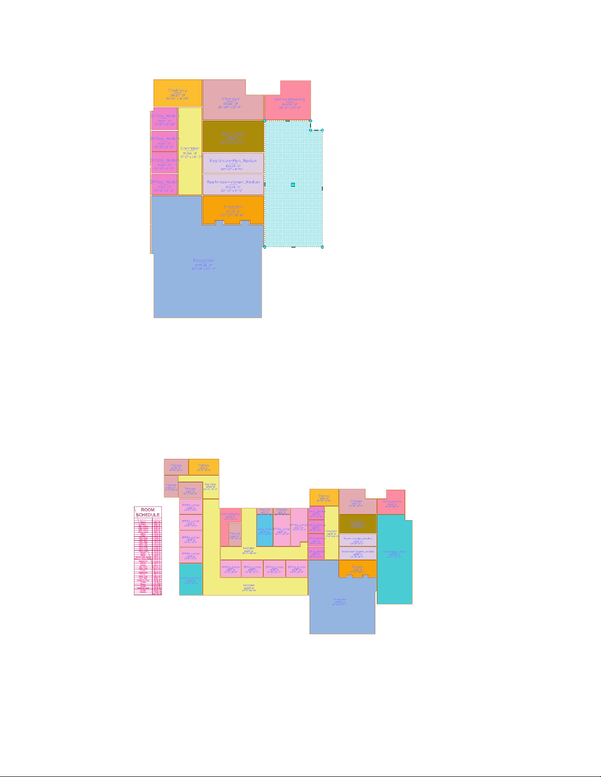
12 Modify the dimensions of a space on the plan, and observe changes in the schedule:
■ Select the large conference room on the right side of the space plan to display editing grips.
■ Press and hold SHIFT, and select the 2 round bottom conference room grips so they display as red.
■ Release SHIFT, and select and drag 1 of the red grips down to enlarge the room.
The exact dimensions are not important, but ensure that the conference room is noticeably larger.
Notice the space tag reports the new area and dimensions after you resize the room.
■ Press ESC to hide the space grips.
The space resizes automatically to fit the new larger boundary. The room schedule displays a diagonal line
across it, indicating that the information in the schedule is no longer current, as the conference room size
has changed.
13 Update the schedule:
■ Select the schedule to display grips, right-click, and click Update Schedule Table.
■ Zoom to the schedule, and view the new area that is reported for Conference_Room.
12 | Chapter 1 Getting Started
Page 17
14 On the Standard toolbar, click (Undo) until the space is restored to its original dimensions.
15 Update the schedule again.
16 On the Standard toolbar, click (Save).
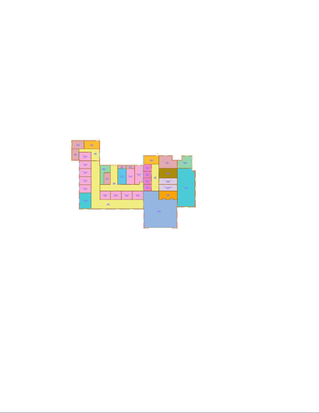
Creating Color-Filled Presentation Plans
In this exercise, you use a feature in AutoCAD Architecture called a display theme to rapidly create 2 different graphic
reports of the spaces on the floor plan. When you create each report, the space data is read, and the spaces fill with
color depending on the current report criteria. A legend that you place near the color-filled floor plan reports the space
data and matches it to the fill colors on the plan.
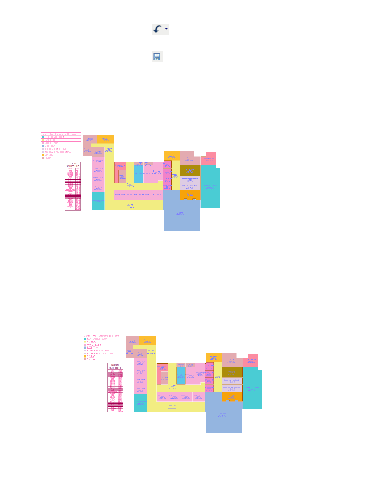
1 Create a display theme that identifies the spaces on the floor plan by type (Reception, Conference, etc.):
■ On the Getting_Started tool palette, click the Theme - Space Style - Commercial tool.
The display theme reads the space property set data on the objects in the drawing and prompts you
to place a legend in the drawing.
■ Specify a point above the room schedule to place the upper-left corner of the legend.
■ Press ENTER to place the legend at the current drawing scale.
The display theme style reports the spaces by commercial type. Color fills are automatically added to
the space plan according to rules set in the display theme style, and the legend displays the space data
that coordinates with the color fills. The color fills used by this display theme are identical to the colors
used by the space tools, but in the next step, you apply a display theme that uses different color fills.
Creating Color-Filled Presentation Plans | 13
Page 18
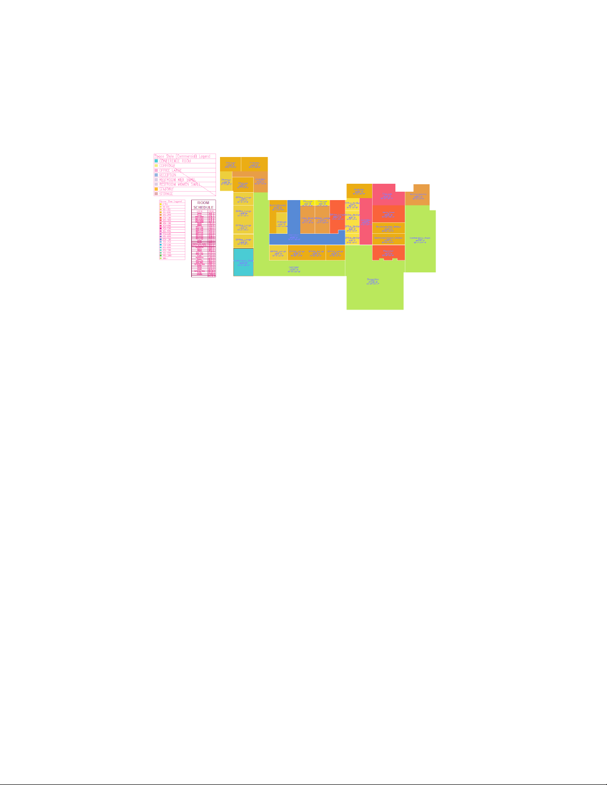
2 Create a different theme that identifies the spaces by size:
■ On the Getting Started tool palette, click the Theme - Space Size tool.
■ Specify a point to the left of the room schedule to place the upper-left corner of the legend.
■ Press ENTER to place the legend.
Notice that the legend associated with the 1st theme displays a line across it, signalling that it is out
of date. To apply 2 themes to the same plan at the same time, or apply more than 1 theme to different
plans, you must have separate copies of the plans in separate model space viewports.
3 Restore the original theme, Space Style - Commercial, and delete the Space Size legend:
■ Select the Space Style (Commercial) legend, right-click, and click Apply Display Theme.
■ Select the Space Size legend, and press DELETE.
4 Click File menu ➤ Save, and leave 01 Spaces open.
Another way you can use display themes is to create a thematic plan sheet, on which you place several
instances of the floor plan view in different paperspace viewports. You can then apply a different display
theme to each viewport, producing a comprehensive visual layout plan. The graphic representation of the
plan information is not limited to the color fills used in this exercise. You can set your display theme style
to use hatch patterns, True Color, and Pantone® and RAL colors.
Laying Out a Floor Plan
In this exercise, you develop a floor plan from a 2D linework sketch created in AutoCAD. You open the drawing in
AutoCAD Architecture, and add it to the Getting Started project as the 01 Floor plan construct. Using the purpose-built
design tools included in AutoCAD Architecture, you quickly and easily convert the linework in the sketch to interior
and exterior walls, and then add doors, windows, stairs, and spaces. Because you are working with design objects that
14 | Chapter 1 Getting Started
Page 19

function like their real-world counterparts, you have complete control over your design as you define their dimensions
and placement.
1 Open the AutoCAD drawing that contains a floor plan sketch:
■ Click File menu ➤ Open.
■ Navigate to C:\My Documents\Autodesk\My Projects\Getting_Started_I [Getting_Started_M].
■ Select 01 Walls Layout.dwg, and click Open.
A sketch similar to the one that you used to create the space plan displays. To use it to create a floor
plan, you need to assign it to the project as a logical piece of the building, the first floor construct.
2 Save the sketch as a construct:
■ With 01 Walls Layout open, on the Project Navigator, right-click the Constructs folder, and click Save
Current Dwg as Construct.
■ On the Add Construct worksheet, click the Name field, and enter 01 Floor.
■ Click in the Description field, enter First floor, and click OK.
■ On the Add Construct worksheet, under Assignments, for Level 1, select Division 1, and click OK.
Notice the open drawing has been renamed 01 Floor, and displays in the Constructs folder on the
Project Navigator.
3 Convert the exterior linework to exterior walls:
■ On the Getting_Started tool palette, right-click the Exterior Wall tool, and click Apply Tool Properties
to ➤ Linework.
■ Select the black outer linework on the floor plan sketch, and press ENTER.
Laying Out a Floor Plan | 15
Page 20
■ On the command line, enter y (Yes), and press ENTER.
The exterior linework is converted to walls that display editing grips.
■ Press ESC to hide the grips.
The walls clean up automatically, and the software places them on the correct layer.
Now that the exterior walls have been created, the height of the walls needs to be adjusted to accommodate
the 10' [3300 mm] floor-to-floor heights in the building. Making this change is easy - just select the walls
and change their properties.
4 Change the height of the exterior walls:
■ Select 1 of the exterior walls, right-click, and click Select Similar.
■ If the Properties palette is not open, right-click again, and click Properties.
■ On the Properties palette, under Dimensions, for Base height, enter 10' [3300 mm].
■ For Justify, verify that Right is selected.
■ Press ESC to hide the grips.
5 Convert the interior wall linework to interior walls:
■ On the Getting_Started tool palette, right-click the Interior Wall tool, and click Apply Tool Properties
to ➤ Linework.
16 | Chapter 1 Getting Started
Page 21
■ Select the black linework that represents the interior partition walls, and press ENTER.
■ On the command line, enter y, and press ENTER.
■ On the Properties palette, under Dimensions, for Base height, enter 9' [3000 mm].
■ For Justify, select Center.
■ Press ESC to hide the interior wall grips.
The interior walls display on the floor plan and clean up automatically with the exterior walls.
Now that the walls are complete, you can add doors and windows. When you add doors and windows,
you can center them in walls, offset them specific distances from other walls on the plan, or place them
freely. Both windows and doors automatically attach to the wall in which you insert them and trim
automatically.
6 If necessary, turn on dynamic input to display dimensions as you insert doors and windows:
■ On the application status bar, click DYN to turn it on.
7 Center a double door in the wall between the corridor and the reception area:
■ On the Getting_Started tool palette, click the Hinged - Double - Full Lite door tool.
■ On the Properties palette, under Dimensions, for Standard sizes, select 5'-0'' X 7'-0'' [1500 mm X 2000
mm].
■ Under Location, for Position along wall, select Offset/Center.
■ Select the vertical wall between the corridor and the reception area, and move the cursor along the
wall.
Laying Out a Floor Plan | 17
Page 22

Because you selected Offset/Center for the Location property of the door, dynamic dimensions display
the door as centered in the wall, or as offset an automatic distance from the end of the wall segment.
■ Move the cursor horizontally.
By moving the cursor horizontally, you can change the swing side of the door.
■ When the door is centered in the wall, and the door swings into the interior of the corridor, click to
place the door.
8 Add a sliding double door to the top exterior wall of the corridor above the one to which you added a
double door:
■ On the Getting_Started tool palette, click the Sliding - Double - Full Lite door tool.
■ On the Properties palette, under Dimensions, for Standard sizes, select 8'-0'' X 6'-8'' [1800 mm X 2000
mm].
■ Under Location, for Position along wall, select Offset/Center.
■ Select the top exterior wall of the corridor.
18 | Chapter 1 Getting Started
Page 23

■ When the door is centered in the exterior corridor wall between the left and right interior corridor
walls, click to place the door.
9 Add an exterior door to each stairway:
■ On the Getting_Started tool palette, click the Hinged - Single - Exterior door tool.
■ On the Properties palette, under Dimensions, for Standard sizes, select 3'-0'' X 7'-0'' [900 mm X 2000
mm].
■ Under Location, for Position along wall, select Offset/Center.
■ For Automatic offset, enter 10'' [200 mm].
■ In the upper-left corner of the building, select the top horizontal exterior wall.
■ Move the cursor along the wall until the dynamic dimensions display the door as offset 10'' [200 mm]
from the exterior vertical wall on the right.
■ Click to place the door.
■ Using the same offset distance, place another exterior door in the stairway in the upper-right corner
of the building.
Laying Out a Floor Plan | 19
Page 24

10 Add interior doors:
■ On the Getting_Started tool palette, click the Hinged - Single - Full Lite door tool.
■ On the Properties palette, under Dimensions, for Standard sizes, select 3'-0'' X 7'-0'' [900 mm X 2000
mm].
■ Using a 6'' [150 mm] automatic offset and the center option, place the doors on the floor plan as
shown:
11 Add exterior windows:
■ On the Getting_Started tool palette, click the Window tool.
■ On the Properties palette, under Dimensions, for Standard sizes, select 5'- 0'' X 5'-0'' [900 mm X 900
mm].
20 | Chapter 1 Getting Started
Page 25

■ Place windows on the floor plan as shown, using a 6'' [150 mm] automatic offset and the center option.
■ When you finish placing the windows, press ESC to end the command.
12 Place a stair in the stairway in the upper-left corner of the floor plan:
■ Click Format menu ➤ Options.
■ On the AEC Object Settings tab, under Stair Settings, for Calculator Limits, select Relaxed, and click
OK.
This setting displays the stair without an error if it violates the calculation limits that you specify when
you create the stair. If you were creating a stair that needed to adhere to limits set by a building code,
you would use the Strict setting to display a red marker on the stair when it violated the calculation
limits.
■ On the Getting_Started tool palette, click the Stair tool.
■ On the Properties palette, under General, for Shape, select U-shaped.
■ For Turn type, verify that 1/2 landing is selected.
■ For Horizontal orientation, select Clockwise.
■ For Vertical orientation, select Up.
■ Under Dimensions, for Justify, select Outside.
■ On the command line, enter near to, and select a point on the bottom horizontal stairway wall.
■ Turn on ORTHO, move the cursor directly up, and select a point on the inside of the top horizontal
stairway wall, perpendicular to the one you just selected.
Laying Out a Floor Plan | 21
Page 26

■ Press ESC to end the stair command, and select the stair to display its grips.
■ Select and move the square Location grip to adjust the position of the stair in the stairway.
■ Press ESC to hide the stair grips.
13 Use the same method, place another stair in the stairway in the upper-right portion of the building.
Now that you have added walls, doors, and windows to the floor plan, apply different display configurations
to the floor plan. The objects on the floor plan display differently depending on the display configuration
you apply. This makes it easy to shift from this floor plan view to a presentation view or to a reflected
ceiling plan view, without creating new views or drawings.
14 View the floor plan in different display configurations:
■ On the drawing window status bar, select the arrow next to Medium Detail.
■ On the flyout menu that displays, select Presentation, and view the changes to the floor plan that
display.
■ Continue to apply different display configurations, such as Reflected, Low Detail, and High Detail.
■ After viewing the available display configurations, restore the Medium Detail configuration.
Next, add spaces to the floor plan. The spaces that you create are associative to the walls; if you move a
wall to change the dimensions of a room, the space automatically resizes and the space tag reports the new
area.
22 | Chapter 1 Getting Started
Page 27
15 Add spaces to the floor plan:
■ Click Format menu ➤ Options.
■ On the AEC Setting tab, under Space Settings, verify that Automatically update associative spaces is
selected, and click OK.
■ On the Getting_Started tool palette, click the Reception space tool.
■ On the Properties palette, under General, for Style, verify that Reception is selected.
■ For Tag, select Aec7_Space_Tag [M_Aec7_Space_Tag].
■ For Create type, select Generate.
■ For Associative, verify that Yes is selected.
■ Under Generate Space, for Filter boundary set, select Aec objects, lines, arcs, polylines, and circles.
■ Under Component Dimensions, for Geometry type, select 2D.
■ Move the cursor into the reception area, and click to create a space.
■ Continue to add the other spaces on the floor plan, using the appropriate space tools.
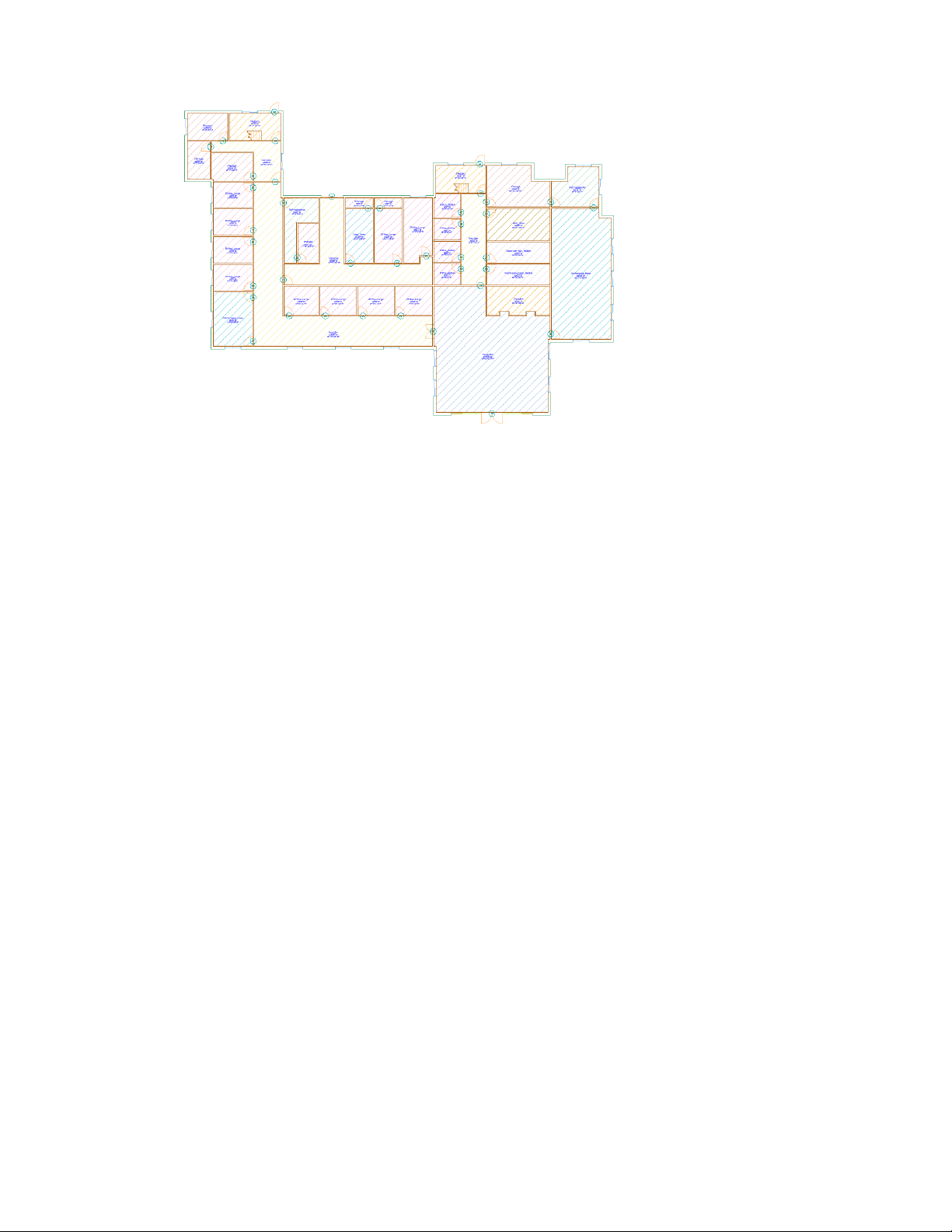
16 On the drawing window status bar, select the Low Detail display configuration.
This display configuration displays the spaces with colored hatch patterns and reveals some of the hidden
and misplaced space tags.
17 Reposition the space tags as necessary.
18 Save and close the 01 Floor construct.
Next, schedule the doors and windows on the floor plan.
Creating Schedules
In this exercise, you schedule the doors and windows on the first floor of the building. Schedules and other annotation
are typically placed in view drawings within the project, so you must create a view that externally references the 01
Floor construct before you can create the schedules.
After you create the view, you tag the doors and windows in the view. The tags let you extract property set data from
the doors and windows. This data is reported in door and window schedules, which you create after you place the tags.
Creating Schedules | 23
Page 28

In the next exercise, you make revisions to the floor plan and learn how you can quickly update these schedules,
keeping your drawing information up to date across the project.
1 Create a view drawing in which to dimension the floor plan:
■ On the Project Navigator, click the Views tab.
■ Select the Views folder, right-click, and click New View Dwg ➤ General.
■ On the Add General View worksheet, click the Name field, enter 01 Plan, and click Next.
■ For Level 1, select Division 1, and click Next.
■ Under Constructs, verify that 01 Floor and Entry Curtain Wall are selected, clear all other constructs,
and click Finish.
■ Open the new view drawing, 01 Plan.
■ If a yellow Unreconciled New Layers bubble displays in the lower-right corner of your screen, click the
blue link to open the Layer Manager, select the layers, and click OK.
■ On the Navigation toolbar, click the Zoom flyout, and click .
A view of the floor plan displays.
2 On the drawing window status bar, select the Low Detail display configuration.
The spaces in the plan view display hatch patterns, and the doors and windows on the floor plan are visible.
3 In the 01 Plan view drawing, beginning with the curtain wall entry door, tag the doors on the floor plan
to include them in a door schedule:
■ On the Getting Started tool palette, click the Door Tag tool.
■ Select door in the curtain wall entry, and press ENTER to center the tag on the door.
■ In the Edit Property Set Data dialog, for Number, verify that 01 displays, and click OK.
■ On the command line, enter m.
■ Select the other doors on the plan, and press ENTER.
24 | Chapter 1 Getting Started
Page 29
■ In the Edit Property Set Data dialog, click OK.
4 Verify that the door tags are numbered sequentially. If they are not, use the Renumber Data Tool on the
Getting_Started tool palette to renumber the tags:
■ Click the Renumber Data Tool.
■ In the Data Renumber dialog, for Property Set, verify that DoorObjects is selected.
■ For Property, verify that Number is selected.
■ For Start Number and Increment, verify a value of 1.
■ Click OK, select the curtain wall entry door and the other doors on the plan, and press ENTER.
5 Create the door schedule:
■ On the Getting_Started tool palette, click the Door Schedule tool.
■ On the Properties palette, under Selection, for Scan xrefs, verify that Yes is selected.
■ On the command line, enter all, and press ENTER twice.
■ Specify a point on the left side of the floor plan view to place the upper-left corner of the schedule.
■ Press ENTER to place the schedule at the current drawing scale.
■ Zoom to a line on the schedule, and view the door information.
6 Tag the windows on the floor plan view to include them in a separate window schedule:
■ On the Getting_Started tool palette, click Window Tag.
Creating Schedules | 25
Page 30

■ Select the bottom window in the left exterior wall of the conference room on the lower-left corner of
the plan, move the cursor slightly to the left of the wall, and click to place the tag.
■ In the Edit Property Set Data dialog, click OK.
■ On the command line, enter m, and tag the remaining windows.
If necessary, adjust the position of some of the window tags so they are located on the outside of the
walls.
7 Create the window schedule:
■ On the Getting_Started tool palette, click the Window Schedule tool.
■ Follow the previous steps to create the window schedule.
8 Save 01 Plan, and leave it open.
26 | Chapter 1 Getting Started
Page 31
Making Floor Plan Revisions
In this exercise, you make several revisions to the 01 Floor plan. You take advantage of the many features of AutoCAD
Architecture that make it easy to adjust any of the objects in your design. To edit the objects on your floor plan, you
can change object properties, use object grips, or use dynamic dimensions.
1 On the Constructs tab of the Project Navigator, double-click the 01 Floor construct.
The interior doors on the floor plan, Hinged - Single - Full Lite, contain a pane of glass. This type of door
is not suitable for either the storage room or the restroom. Rather than changing only the storage and
restroom doors, you decide to replace all the interior doors on the floor plan with a solid door type.
2 Change the style of 1 of the interior doors on the floor plan:
■ On the Getting_Started tool palette, right-click the Hinged - Single door tool, and click Apply Tool
Properties to ➤ Door.
■ Select an interior door on the floor plan, and press ENTER.
■ On the Properties palette, under General, for Style, view the new Hinged - Single style that is applied
to the door.
■ Press ESC to hide the door grips.
3 Change the style of the remaining interior doors:
■ Select another door that has the Hinged - Single - Full Lite style applied to it, right-click, and click
Select Similar.
■ On the Properties palette, under General, for Style, select Hinged - Single.
■ Press ESC to hide the door grips.
4 Flip the hinge side of an interior door:
■ Select the door in the bottom wall of the large office next to the copy room.
Making Floor Plan Revisions | 27
Page 32
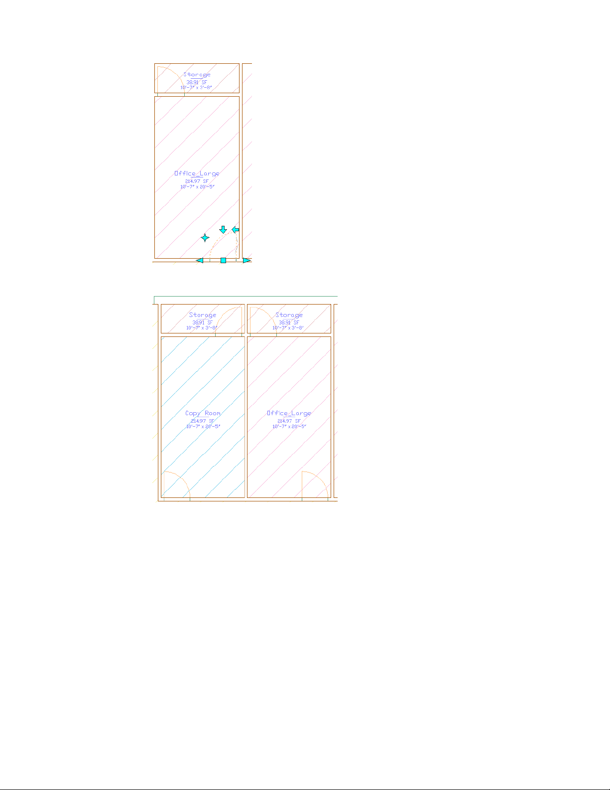
■ Click the left arrow grip to flip the hinge side of the door.
■ Press ESC to hide the grips.
Next, change the dimensions of the exterior wall of the conference room on the right side of the building
to see how it affects the floor plan design.
5 Grip-edit the right exterior wall of the conference room on the right side of the building:
■ Select the right vertical exterior wall of the conference room.
■ Select and drag the square Location grip to move the wall to the right.
28 | Chapter 1 Getting Started
Page 33

Notice that the dynamic dimensions display the changing dimension of the wall.
■ Click to place the wall, or enter a larger value in the dynamic dimension.
The spaces are associative to the walls, so they update when you place the wall. The space tags also
report the new area for the room affected by the change.
6 On the Standard toolbar, click (Undo) until the wall is restored to its original dimensions.
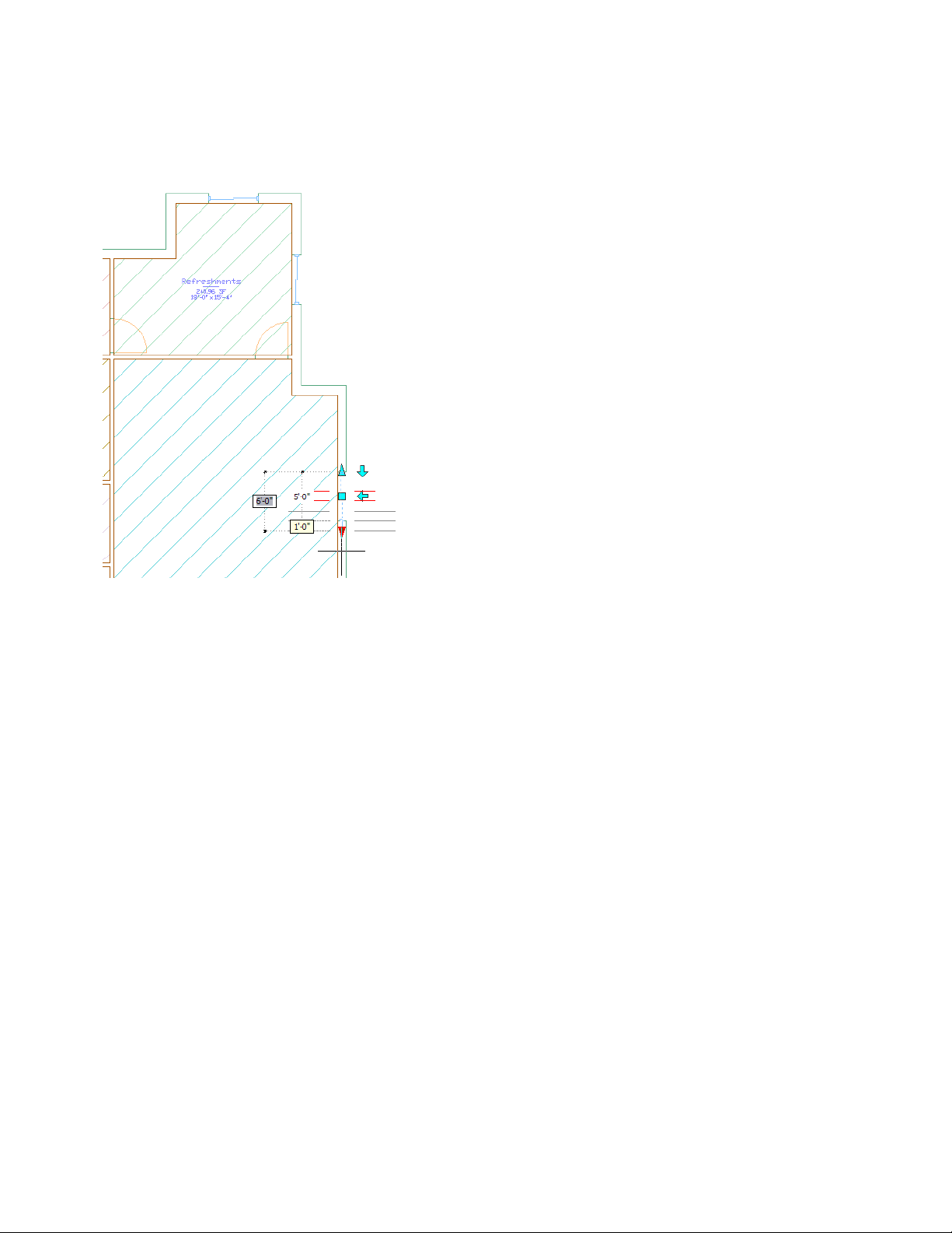
7 Grip-edit a window to change its width:
■ Select the top window in the right wall of the conference room, and select the bottom triangular width
grip.
Making Floor Plan Revisions | 29
Page 34
■ Drag the grip down until the dynamic dimensions display a width of 6' [1800 mm], and click to resize
the window.
■ With the window still selected, on the Properties palette, for Height, enter 6' [1800 mm].
■ Press ESC to hide the grips.
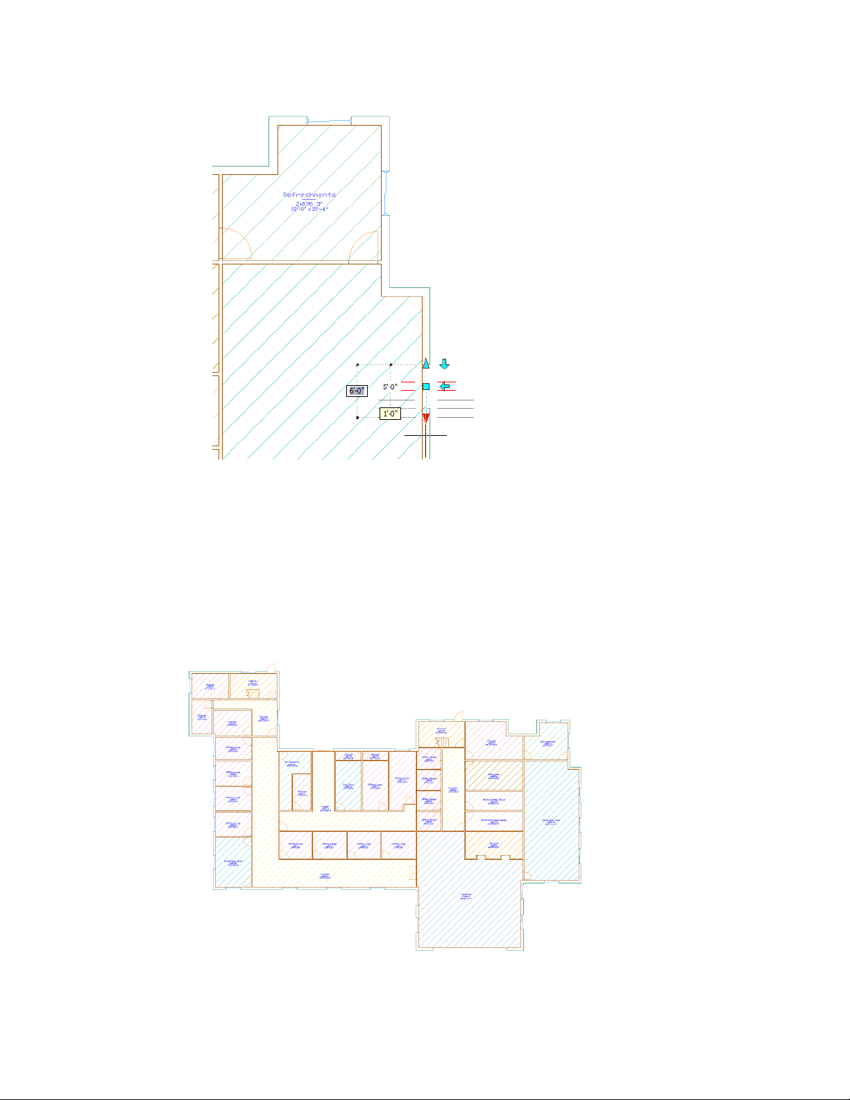
8 Change the size of the remaining windows:
■ Select one of the other windows on the floor plan, right-click, and click Select Similar.
■ On the Properties palette, for Standard sizes, select 6'-0'' X 6'-0'' [1800 mm X 1800 mm].
■ Press ESC to hide the window grips.
9 Add a 6' X 6' [1800 mm X 1800 mm] window centered in the top wall of each stairway.
10 Save and close the 01 Floor Construct.
30 | Chapter 1 Getting Started
Page 35
11 View the changes in the 01 Plan view.
■ Click Window menu ➤ 01 Plan.
■ At the lower right corner of the screen, click the blue link in the yellow bubble that displays to reload
the changes that you made in the 01 Floor construct to the current view.
Notice the windows are resized, but the windows that you placed in both stairways are not tagged or
added to the schedule, and the windows sizes are not updated in the schedule.
12 Tag the stairway windows, and update the window schedule:
■ On the Getting Started tool palette, click Window Tag, select the first window, and place the tag above
the window.
■ In the Edit Property Set Data dialog, under WindowObjects, verify that the number is the next sequential
number after the number of the last window that currently displays in the schedule.
■ Click OK, press ESC.
■ Repeat the same steps to tag the other stairway window.
■ Update the window schedule, and view the new sizes and windows in the schedule.
13 Save and close 01 Plan.
Creating a Section
In this exercise, you create a section through the building. Before you can create the section, you must create the rest
of the building geometry. Construct drawings that include the floor slabs, elevator shaft, and curtain wall entry are
provided for you, but you create the 02-04 Floor constructs and reference the restroom elements onto the 01-04 Floor
constructs.
To create the section, you use a section callout tool to place a section line in the 01 Plan view, and then generate a new
view drawing that contains the section. The new view drawing externally references all of the constructs (and elements
that they reference) that create the office building geometry.
After you create the section, you study the section view, make some design revisions in the building constructs, and
then update the section to include the revisions.
1 Open the 01 Floor construct, and reference the restroom layout elements:
■ On the Project Navigator, click the Constructs tab.
■ Under Constructs, double-click 01 Floor.
■ Under Elements, select Typical Restroom - Men, and drag it to the 01 Floor drawing.
■ Select Typical Restroom - Women, and drag it to the 01 Floor drawing.
■ Save and close 01 Floor.
2 Copy the 01 Floor construct to create constructs for floors 02-04:
■ In the Constructs folder, right-click 01 Floor, and click Copy Construct to Levels.
■ On the Copy Construct to Levels worksheet, under Copy to Levels, select levels 2 - 4, and click OK.
Three copies of 01 Floor are created in the Constructs folder.
Creating a Section | 31
Page 36

■ Select 01 Floor (2), right-click, and click Rename.
■ Enter 02 Floor, and press ENTER to rename the construct.
■ Using the same method, rename the other copies 03 Floor and 04 Floor.
3 Place a callout in the 01 Plan view to define and generate a section view:
■ On Project Navigator, click the Views tab.
■ Under Views, double-click 01 Plan view.
■ On the Getting_Started tool palette, click the Section Mark A2T tool.
■ If necessary, on the application status bar, click ORTHO to turn it on.
■ Beginning in the upper-left corner of the building, specify a point to the left of the exterior storage
room window for the start point of the section line.
■ Move the cursor to the right, and specify a point past the stair in the stairway and in front of the
exterior door.
■ Move the cursor down, and specify a point in the corridor, in front of the door to the horizontal
corridor.
■ Move the cursor to the right until it cuts through the middle window in the exterior wall of the
conference room, and specify the endpoint of the section line outside the building.
■ Press ENTER.
■ Move the cursor up, and specify a point above the building view to define the section view extents.
■ On the Place Callout worksheet, select Generate Section/Elevation, and Place Titlemark.
■ Under Create in, click New View Drawing.
■ On the Add Section/Elevation View, click the Name field, and enter Building Section.
■ Click Next.
■ For Levels 1-5, select Division 1, and click Next to include all 5 floors of the building in the section
view.
■ Under Constructs, select all the constructs except 01 Space Plan, and click Finish.
■ Specify a point above the floor plan in the 01 Plan view to generate the section view.
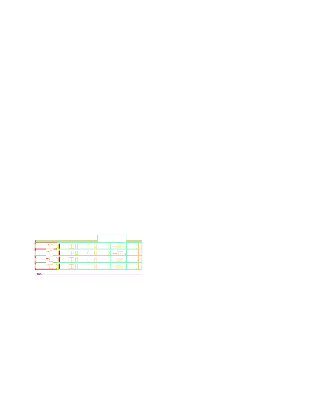
4 Open the new section view:
■ On the Project Navigator, under Views, double-click Building Section.
■ On the Navigation toolbar, click the Zoom flyout, and click .
32 | Chapter 1 Getting Started
Page 37

Notice the section view displays exterior doors on the second, third, and fourth floors, and a stair on
the fourth floor. The exterior doors are only necessary on the first floor of the building, and the stairs
to the roof are not needed.
5 Save and close the Building Section view.
6 Remove all exterior doors in the 02-04 Floor constructs:
■ On the Constructs tab of the Project Navigator, double-click 02 Floor.
■ Select the 2 exterior stairway doors and the sliding door, and press DELETE.
■ Save and close 02 Floor.
■ Repeat the same steps for 03 Floor and 04 Floor.
After you delete the doors in the 04 Floor construct, leave it open, and continue to the next step.
7 Remove the 2 stairs in the 04 Floor construct, and save and close it.
8 Open the section view, and update the section:
■ On the Views tab of the Project Navigator, double-click Building Section.
■ Select the section, right-click, and click Refresh.
Notice that the exterior doors and fourth floor stairs are no longer visible in the section view.
9 Save and close the Building Section view.
Detailing Your Design
In this exercise, you create a window detail. You create a new view drawing, and reference the section view into the
detail view to use as a guide in creating the detail. To draw the detail, you use detail tools on the project palette. These
tools were created from the detail component databases available in AutoCAD Architecture.
Detailing Your Design | 33
Page 38

After you draw the detail components, you create another view for the detail, and add reference keynotes to the detail
in this view. You use a smart keynoting tool to select the component, draw a leader line, and the reference key and
related note automatically display. The key and note are extracted from the property set data of the detail component.
NOTE To complete the metric version of this exercise, you must have the UK metric content installed on your system.
1 Create a new view in which to create a detail:
■ On Views tab of the Project Navigator, right-click the Views folder, and click New View Dwg ➤ Detail.
■ On the Add Detail View worksheet, click the Name field, and enter Window Detail.
■ Click Next, and verify that no levels are selected.
■ Click Next, verify that no constructs are selected, and click Finish.
■ On the Project Navigator, double-click Window Detail.
An empty view drawing opens.
2 Reference the section view in the detail view for use as an underlay:
■ On the Views tab of the Project Navigator, select and drag Building Section to the drawing.
■ On the Navigation toolbar, click the Zoom flyout, and click .
The section view that you created in the previous exercise displays in the detail drawing as an external
reference. You start to create your detail by adding detail components on top of the window geometry
in the section view.
34 | Chapter 1 Getting Started
Page 39
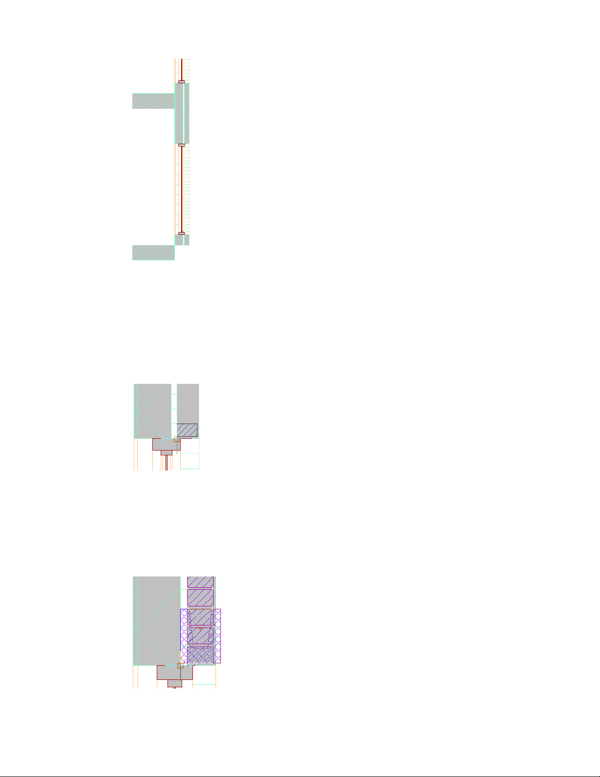
■ Zoom in around the top of the first floor window on the right exterior wall.
3 Begin detailing by adding a course of bricks to the view:
■ On Getting_Started tool palette, click the Standard Brick - 3/8'' Jt [Standard Brick - 10mm] tool.
■ On the application status bar, verify that ORTHO and OSNAP are on, and an endpoint osnap is selected.
■ On the command line, enter c (Count) to insert a course of bricks.
■ Enter 10 to specify the number of bricks in the course, and press ENTER.
■ Select the endpoint shown below to place the lower-left corner of the brick course.
■ Move the cursor up, and click to place the course.
■ Press ESC.
4 Add a bond beam to the detail:
■ On the Getting_Started tool palette, click the 6'' x 8'' Bond Beam [Bond Beam 150 x 200] tool.
■ Move your cursor over the endpoint shown.
■ On the command line, enter y (Y flip), press ENTER, and click to place the bond beam.
Detailing Your Design | 35
Page 40
■ Press ESC.
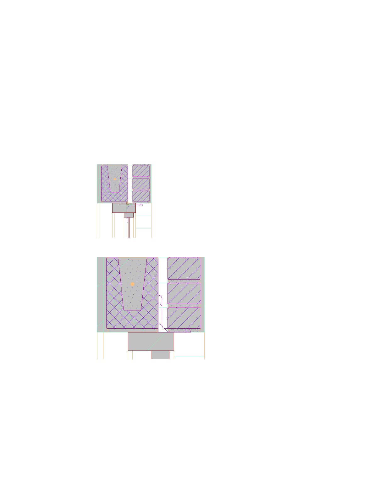
5 Add a CMU course above the bond beam in the detail:
■ On the Getting_Started tool palette, click the 6'' x 8'' x 8'' CMU [140 x 200 x 400mm Block] tool.
■ On the command line, enter c (Count) to insert a CMU course.
■ Enter 2 to specify the number of CMUs in the course, and press ENTER.
■ Select the upper-right endpoint of the bond beam, and click to place the lower right corner of the
CMU course.
■ Move the cursor up, and click to place the course.
■ Press ESC.
6 Add a steel angle to the detail:
■ On the Getting_Started tool palette, click the L4x3.5x0.375 angle [Lintel] tool.
■ Move your cursor over the lower right endpoint of the brick course.
■ On the command line, enter x (X flip) [y (Y flip)], press ENTER, and position the angle as shown.
If you are creating the metric detail, you may need to adjust the position of the angle.
■ Press ESC.
7 Add a window head to the detail:
■ On the Getting_Started tool palette, click the Storefront Head at Finish [115mm Shopfront Head at
Finish] tool.
36 | Chapter 1 Getting Started
Page 41
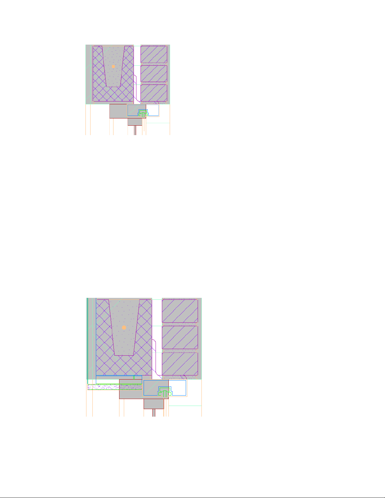
■ Turn off OSNAP, move the cursor until the right side of window head aligns with the bottom right of
the angle, and click to place it.
■ Press ESC.
8 Add hat channels to the detail:
■ On the Getting_Started tool palette, click the 7/8'' Hat Channel [22mm Hat Channel] tool.
■ On the Properties palette, for View, select Elevation.
■ On the command line, enter near to, and select a point on the underside of the bond beam,
perpendicular to the upper-left corner of the window head.
■ Move the cursor to the lower-left endpoint of the bond beam, and click to place the channel.
■ Select the lower-left endpoint of the channel that you just placed, move the cursor up, and select the
upper-left endpoint of the second CMU.
■ Press ESC.
9 Add gypsum wall board to the detail:
■ On the Getting_Started tool palette, click the GWB [19mm Gypsum Wallboard] tool.
■ At the bottom of the detail, select the lower-right endpoint of the horizontal hat channel.
■ Move the cursor to the left, and select the lower-left endpoint of the vertical hat channel.
Detailing Your Design | 37
Page 42

■ Select the lower-left endpoint of the wall board that you just placed, enter y (Y flip), press ENTER, move
the cursor up, and select the top left endpoint of the vertical hat channel.
■ Press ESC.
10 Detach the section view that you referenced to create the detail.
■ On the drawing window status bar, click .
■ On the External References palette, under File References, click Building Section.
■ Right-click, and click Detach.
■ Close the External References palette.
11 Create a new model space view for the detail with an appropriate scale:
■ On Project Navigator, under Views, select Window Detail, right-click, and click New Model Space View.
■ On the Add Model Space View worksheet, click the Name field, and enter Window Detail@Head.
■ For Scale, select 1 1/2'' = 1'0'' [1:10].
■ On the right side of the worksheet, click , and draw a window selection around the detail.
■ In the Add Model Space worksheet, click OK.
■ In the Project Navigator, under Window Detail, open the new Window Detail@Head view.
12 Add a cut line to the detail:
■ On the Project Navigator, click Window Detail@Head to display the extents of the model space view.
■ On the application status bar, turn ORTHO on.
■ On the Getting_Started tool palette, click the Cut Line tool.
■ Specify a point to the left of the second CMU in the detail, but within the extents of the model space
view.
■ Move the cursor to the right side of the detail, and specify an endpoint for the cut line.
38 | Chapter 1 Getting Started
Page 43

■ Select a point above the detail components to specify the cut line extents.
The detail is now properly framed and is ready to be annotated.
13 Add keynotes to the detail components:
■ On the Getting_Started tool palette, click the Keynote (Straight Leader) tool.
■ Select the top brick in the brick course as the component to keynote, and select any point on the brick.
■ Move the cursor to the right, and click to select the second point of the leader.
■ Press ENTER twice to place the keynote.
TIP To turn off the keynote background, on the command line, enter FIELDDISPLAY, and enter 0.
■ Use the same technique to add keynotes to the other components in the detail.
To repeat the keynoting command, press the SPACEBAR. To keep multiple keynotes aligned, align the
second point of each consecutive keynote leader with left edge of the keynote above it.
14 Create a presentation sheet on which to place the detail and other project views:
■ On the Project Navigator, click the Sheets tab.
■ Under Getting Started, expand Architectural.
■ Under Architectural, right-click General, and click New ➤ Sheet.
■ On the New Sheet worksheet, for Number enter A101.
■ For Sheet title, enter Client Presentation.
Notice that the file name is created automatically from the number and title that you enter.
■ Click OK.
15 Open the Client Presentation sheet:
■ On the Project Navigator, under Architectural\General, double-click A101 Client Presentation.
■ Zoom in to the title block on the sheet.
Notice that the title block already contains the title, number, and name of the project.
16 Reference views onto the sheet:
■ On the Project Navigator, click the Views tab.
■ In the Views folder, under Details, select Window Detail@Head.
■ Drag Window Detail@Head to the sheet, and click to place it in the top left corner.
If any part of the detail is obscured, select the view frame, and grip-edit it to resize the view.
■ Reference the 01 Plan view onto the sheet.
17 Save and close the Client Presentation sheet.
Congratulations! You have completed your first project in AutoCAD Architecture. As you continue your
work in AutoCAD Architecture, be sure to use the different learning resources available to you, such as the
online Help, tutorials, and the New Features Workshop.
Detailing Your Design | 39
Page 44

40 | Chapter 1 Getting Started
Page 45

Index
41 | Index
Page 46

42 | Index
 Loading...