

Page 1

AutoCAD 2011
Customization Guide
February 2010
Page 2

©
2010 Autodesk, Inc. All Rights Reserved. Except as otherwise permitted by Autodesk, Inc., this publication, or parts thereof, may not be
reproduced in any form, by any method, for any purpose.
Certain materials included in this publication are reprinted with the permission of the copyright holder.
Trademarks
The following are registered trademarks or trademarks of Autodesk, Inc., and/or its subsidiaries and/or affiliates in the USA and other countries:
3DEC (design/logo), 3December, 3December.com, 3ds Max, Algor, Alias, Alias (swirl design/logo), AliasStudio, Alias|Wavefront (design/logo),
ATC, AUGI, AutoCAD, AutoCAD Learning Assistance, AutoCAD LT, AutoCAD Simulator, AutoCAD SQL Extension, AutoCAD SQL Interface,
Autodesk, Autodesk Envision, Autodesk Intent, Autodesk Inventor, Autodesk Map, Autodesk MapGuide, Autodesk Streamline, AutoLISP, AutoSnap,
AutoSketch, AutoTrack, Backburner, Backdraft, Built with ObjectARX (logo), Burn, Buzzsaw, CAiCE, Civil 3D, Cleaner, Cleaner Central, ClearScale,
Colour Warper, Combustion, Communication Specification, Constructware, Content Explorer, Dancing Baby (image), DesignCenter, Design
Doctor, Designer's Toolkit, DesignKids, DesignProf, DesignServer, DesignStudio, Design Web Format, Discreet, DWF, DWG, DWG (logo), DWG
Extreme, DWG TrueConvert, DWG TrueView, DXF, Ecotect, Exposure, Extending the Design Team, Face Robot, FBX, Fempro, Fire, Flame, Flare,
Flint, FMDesktop, Freewheel, GDX Driver, Green Building Studio, Heads-up Design, Heidi, HumanIK, IDEA Server, i-drop, ImageModeler, iMOUT,
Incinerator, Inferno, Inventor, Inventor LT, Kaydara, Kaydara (design/logo), Kynapse, Kynogon, LandXplorer, Lustre, MatchMover, Maya,
Mechanical Desktop, Moldflow, Moonbox, MotionBuilder, Movimento, MPA, MPA (design/logo), Moldflow Plastics Advisers, MPI, Moldflow
Plastics Insight, MPX, MPX (design/logo), Moldflow Plastics Xpert, Mudbox, Multi-Master Editing, Navisworks, ObjectARX, ObjectDBX, Open
Reality, Opticore, Opticore Opus, Pipeplus, PolarSnap, PortfolioWall, Powered with Autodesk Technology, Productstream, ProjectPoint, ProMaterials,
RasterDWG, RealDWG, Real-time Roto, Recognize, Render Queue, Retimer,Reveal, Revit, Showcase, ShowMotion, SketchBook, Smoke, Softimage,
Softimage|XSI (design/logo), Sparks, SteeringWheels, Stitcher, Stone, StudioTools, ToolClip, Topobase, Toxik, TrustedDWG, ViewCube, Visual,
Visual LISP, Volo, Vtour, Wire, Wiretap, WiretapCentral, XSI, and XSI (design/logo).
All other brand names, product names or trademarks belong to their respective holders.
Disclaimer
THIS PUBLICATION AND THE INFORMATION CONTAINED HEREIN IS MADE AVAILABLE BY AUTODESK, INC. "AS IS." AUTODESK, INC. DISCLAIMS
ALL WARRANTIES, EITHER EXPRESS OR IMPLIED, INCLUDING BUT NOT LIMITED TO ANY IMPLIED WARRANTIES OF MERCHANTABILITY OR
FITNESS FOR A PARTICULAR PURPOSE REGARDING THESE MATERIALS.
Published by:
Autodesk, Inc.
111 McInnis Parkway
San Rafael, CA 94903, USA
Page 3

Contents
Chapter 1 Basic Customization . . . . . . . . . . . . . . . . . . . . . . . . 1
Overview of Customization . . . . . . . . . . . . . . . . . . . . . . . . 1
Organize Program and Support Files . . . . . . . . . . . . . . . . . . . . 4
Overview of File Organization . . . . . . . . . . . . . . . . . . . . 4
Multiple Configurations . . . . . . . . . . . . . . . . . . . . . . . 7
Multiple Drawing Folders . . . . . . . . . . . . . . . . . . . . . . 8
Locate Customized Files . . . . . . . . . . . . . . . . . . . . . . . 10
Locate Data Link Files . . . . . . . . . . . . . . . . . . . . . 10
Locate Plot Style Files . . . . . . . . . . . . . . . . . . . . . 11
Locate Plotter Files . . . . . . . . . . . . . . . . . . . . . . 11
Locate the PMP File . . . . . . . . . . . . . . . . . . . . . . 12
Locate Support Files . . . . . . . . . . . . . . . . . . . . . . 13
Locate Drawing Template Files . . . . . . . . . . . . . . . . 16
Locate Texture Files . . . . . . . . . . . . . . . . . . . . . . 17
Customize a Publish to Web Template . . . . . . . . . . . . . . . . . . 17
Define Custom Commands . . . . . . . . . . . . . . . . . . . . . . . 20
Define External Commands . . . . . . . . . . . . . . . . . . . . . 20
Create Command Aliases . . . . . . . . . . . . . . . . . . . . . . 24
Record and Modify Action Macros . . . . . . . . . . . . . . . . . . . . 25
Overview of Action Macros . . . . . . . . . . . . . . . . . . . . . 25
Work with the Action Recorder . . . . . . . . . . . . . . . . . . . 28
Record an Action Macro . . . . . . . . . . . . . . . . . . . . . . 28
Record an Action Macro with the Action Recorder . . . . . . 29
Action Node Icons . . . . . . . . . . . . . . . . . . . . . . 33
iii
Page 4

Work with User Interface Elements . . . . . . . . . . . . . . 36
Manage and Modify Action Macros . . . . . . . . . . . . . . . . . 37
Manage Action Macros . . . . . . . . . . . . . . . . . . . . 38
Insert User Messages . . . . . . . . . . . . . . . . . . . . . 41
Pause for User Input . . . . . . . . . . . . . . . . . . . . . . 43
Work with Coordinates . . . . . . . . . . . . . . . . . . . . 44
Insert Base Points . . . . . . . . . . . . . . . . . . . . . . . 46
Work with Object Selections . . . . . . . . . . . . . . . . . 47
Tips for Using the Action Recorder . . . . . . . . . . . . . . . . . 48
Examples of Action Macros . . . . . . . . . . . . . . . . . . . . . 52
Create a New Layer and Draw Objects . . . . . . . . . . . . 52
Insert a Block and Change a Dynamic Property
Value . . . . . . . . . . . . . . . . . . . . . . . . . . . . . 57
Modify Circles with the Properties Palette . . . . . . . . . . 59
Chapter 2 Custom Linetypes . . . . . . . . . . . . . . . . . . . . . . . . . 63
Overview of Linetype Definitions . . . . . . . . . . . . . . . . . . . . . 63
Simple Custom Linetypes . . . . . . . . . . . . . . . . . . . . . . . . . 64
Text in Custom Linetypes . . . . . . . . . . . . . . . . . . . . . . . . . 68
Shapes in Custom Linetypes . . . . . . . . . . . . . . . . . . . . . . . 71
Chapter 3 Custom Hatch Patterns . . . . . . . . . . . . . . . . . . . . . . 75
Overview of Hatch Pattern Definitions . . . . . . . . . . . . . . . . . . 75
Hatch Patterns with Dashed Lines . . . . . . . . . . . . . . . . . . . . 78
Hatch Patterns with Multiple Lines . . . . . . . . . . . . . . . . . . . . 82
Chapter 4 User Interface Customization . . . . . . . . . . . . . . . . . . . 87
Understand User Interface Customization . . . . . . . . . . . . . . . . 87
Overview of the Customization . . . . . . . . . . . . . . . . . . . 87
Use the Customization Environment . . . . . . . . . . . . . . . . 90
Overview of the Customize User Interface (CUI)
Editor . . . . . . . . . . . . . . . . . . . . . . . . . . . . 90
Work with the Customizations In Pane . . . . . . . . . . . 92
Work with the Command List Pane . . . . . . . . . . . . . 93
Work with the Dynamic Display Pane . . . . . . . . . . . . 95
How Customization Has Changed . . . . . . . . . . . . . . . . . 96
Customization Glossary . . . . . . . . . . . . . . . . . . . . . . 103
Work with the Customize User Interface (CUI) Editor . . . . . . . . . 106
Create a Command . . . . . . . . . . . . . . . . . . . . . . . . 106
Create User Interface Elements . . . . . . . . . . . . . . . . . . 108
Create a Quick Access Toolbar . . . . . . . . . . . . . . . . 108
Customize the Ribbon . . . . . . . . . . . . . . . . . . . . 109
Create a Toolbar . . . . . . . . . . . . . . . . . . . . . . . 113
Create a Pull-Down Menu . . . . . . . . . . . . . . . . . . 114
iv | Contents
Page 5

Create a Shortcut Menu . . . . . . . . . . . . . . . . . . . 116
Customize Shortcut Key . . . . . . . . . . . . . . . . . . . 117
Create a Double Click Action . . . . . . . . . . . . . . . . 117
Create a Mouse Button . . . . . . . . . . . . . . . . . . . 118
Create and Modify Workspaces . . . . . . . . . . . . . . . . . . 118
Create a Workspace from the User Interface . . . . . . . . 119
Create a Workspace with the CUI Editor . . . . . . . . . . 120
Create and Manage Customization Files . . . . . . . . . . . . . . . . 122
Basics of Customization Files . . . . . . . . . . . . . . . . . . . 122
Create and Load a Partial CUIx File . . . . . . . . . . . . . . . . 127
Create an Enterprise CUIx File . . . . . . . . . . . . . . . . . . . 131
Find and Replace Commands and Text in a CUIx File . . . . . . 135
Customize Commands . . . . . . . . . . . . . . . . . . . . . . . . . . 142
Overview of Commands . . . . . . . . . . . . . . . . . . . . . . 142
Create, Edit, and Reuse Commands . . . . . . . . . . . . . . . . 144
Create Macros . . . . . . . . . . . . . . . . . . . . . . . . . . . 151
Overview of Macros . . . . . . . . . . . . . . . . . . . . . 151
Use Special Control Characters in Macros . . . . . . . . . . 154
Pause for User Input in Macros . . . . . . . . . . . . . . . 156
Provide International Support in Macros . . . . . . . . . . 158
Use Built-in Commands in Macros . . . . . . . . . . . . . 159
Repeat Commands in Macros . . . . . . . . . . . . . . . . 159
Use Single Object Selection Mode in Macros . . . . . . . . 160
Use Macros to Swap User Interface Elements . . . . . . . . 160
Use Conditional Expressions in Macros . . . . . . . . . . . 162
Use AutoLISP in Macros . . . . . . . . . . . . . . . . . . . 163
Control the Display of Command Items . . . . . . . . . . . . . 165
Assign Search Tags . . . . . . . . . . . . . . . . . . . . . . . . . 171
Create Tooltips and Extended Help for Commands . . . . . . . . 174
Create Status Line Help Messages . . . . . . . . . . . . . . . . . 180
Assign, Create, and Manage Images for Commands . . . . . . . 181
Assign Images to a Command . . . . . . . . . . . . . . . . 181
Create and Edit Custom Images for Commands . . . . . . 184
Manage, Import, and Export Custom Images . . . . . . . . 186
Customize User Interface Elements . . . . . . . . . . . . . . . . . . . 191
Quick Access Toolbars . . . . . . . . . . . . . . . . . . . . . . . 194
Ribbon . . . . . . . . . . . . . . . . . . . . . . . . . . . . . . . 201
Ribbon Panels . . . . . . . . . . . . . . . . . . . . . . . . 201
Ribbon Tabs . . . . . . . . . . . . . . . . . . . . . . . . . 238
Ribbon Contextual Tab States . . . . . . . . . . . . . . . . 244
Toolbars . . . . . . . . . . . . . . . . . . . . . . . . . . . . . . 248
Create and Edit Toolbars . . . . . . . . . . . . . . . . . . . 248
Add Flyouts to a Toolbar . . . . . . . . . . . . . . . . . . . 260
Add, Remove or Switch Toolbar Controls . . . . . . . . . . 265
Pull-down and Shortcut Menus . . . . . . . . . . . . . . . . . . 270
Overview of Pull-Down and Shortcut Menus . . . . . . . . 270
Contents | v
Page 6

Create a Pull-Down Menu . . . . . . . . . . . . . . . . . . 271
Create a Shortcut Menu . . . . . . . . . . . . . . . . . . . 275
Create Submenus . . . . . . . . . . . . . . . . . . . . . . 285
Reference Pull-Down or Shortcut Menus . . . . . . . . . . 288
Swap and Insert Pull-Down Menus . . . . . . . . . . . . . 290
Quick Properties . . . . . . . . . . . . . . . . . . . . . . . . . . 293
Rollover Tooltips . . . . . . . . . . . . . . . . . . . . . . . . . . 302
Keyboard Shortcuts . . . . . . . . . . . . . . . . . . . . . . . . 309
Shortcut Keys . . . . . . . . . . . . . . . . . . . . . . . . 309
Temporary Override Keys . . . . . . . . . . . . . . . . . . 317
Double Click Actions . . . . . . . . . . . . . . . . . . . . . . . 324
Overview of Double Click Actions . . . . . . . . . . . . . . 324
Double Click Action Object Names . . . . . . . . . . . . . 327
Examples of Double Click Actions . . . . . . . . . . . . . 330
Mouse Buttons . . . . . . . . . . . . . . . . . . . . . . . . . . . 331
Overview of Mouse Buttons . . . . . . . . . . . . . . . . . 331
Accept Coordinate Entry in Button Menus . . . . . . . . . 333
Legacy Interface Elements . . . . . . . . . . . . . . . . . . . . . 334
Create Tablet Menus . . . . . . . . . . . . . . . . . . . . . 334
Customize Tablet Buttons . . . . . . . . . . . . . . . . . . 336
Create Screen Menus . . . . . . . . . . . . . . . . . . . . . 337
Create Image Tile Menus . . . . . . . . . . . . . . . . . . 341
Load an AutoLISP File . . . . . . . . . . . . . . . . . . . . . . . . . . 346
Customize Workspaces . . . . . . . . . . . . . . . . . . . . . . . . . . 347
Overview of Workspace Customization . . . . . . . . . . . . . . 347
Control User Interface Elements Outside the CUI Editor . . . . . 361
Control User Interface Elements in the CUI Editor . . . . . . . . 364
Control the Appearance of Palettes . . . . . . . . . . . . . . . . 380
Transfer and Migrate Customization . . . . . . . . . . . . . . . . . . 384
Customize User Interface (CUI) Editor FAQs . . . . . . . . . . . . . . 387
Chapter 5 DIESEL . . . . . . . . . . . . . . . . . . . . . . . . . . . . . . 393
Customize the Status Line . . . . . . . . . . . . . . . . . . . . . . . . 393
Overview of the MODEMACRO System Variable . . . . . . . . . 393
Set MODEMACRO Values . . . . . . . . . . . . . . . . . . . . . 394
Set MODEMACRO with AutoLISP . . . . . . . . . . . . . . . . . 396
DIESEL Expressions in Macros . . . . . . . . . . . . . . . . . . . . . . 399
Catalog of DIESEL Functions . . . . . . . . . . . . . . . . . . . . . . 402
+ (addition) . . . . . . . . . . . . . . . . . . . . . . . . . . . . 402
- (subtraction) . . . . . . . . . . . . . . . . . . . . . . . . . . . 403
* (multiplication) . . . . . . . . . . . . . . . . . . . . . . . . . 403
/ (division) . . . . . . . . . . . . . . . . . . . . . . . . . . . . . 403
= (equal to) . . . . . . . . . . . . . . . . . . . . . . . . . . . . . 404
< (less than) . . . . . . . . . . . . . . . . . . . . . . . . . . . . 404
> (greater than) . . . . . . . . . . . . . . . . . . . . . . . . . . . 405
!= (not equal to) . . . . . . . . . . . . . . . . . . . . . . . . . . 405
vi | Contents
Page 7

<= (less than or equal to) . . . . . . . . . . . . . . . . . . . . . 405
>= (greater than or equal to) . . . . . . . . . . . . . . . . . . . . 406
and . . . . . . . . . . . . . . . . . . . . . . . . . . . . . . . . . 406
angtos . . . . . . . . . . . . . . . . . . . . . . . . . . . . . . . 406
edtime . . . . . . . . . . . . . . . . . . . . . . . . . . . . . . . 407
eq . . . . . . . . . . . . . . . . . . . . . . . . . . . . . . . . . . 409
eval . . . . . . . . . . . . . . . . . . . . . . . . . . . . . . . . . 409
fix . . . . . . . . . . . . . . . . . . . . . . . . . . . . . . . . . 410
getenv . . . . . . . . . . . . . . . . . . . . . . . . . . . . . . . 410
getvar . . . . . . . . . . . . . . . . . . . . . . . . . . . . . . . . 411
if . . . . . . . . . . . . . . . . . . . . . . . . . . . . . . . . . . 411
index . . . . . . . . . . . . . . . . . . . . . . . . . . . . . . . 411
nth . . . . . . . . . . . . . . . . . . . . . . . . . . . . . . . . . 412
or . . . . . . . . . . . . . . . . . . . . . . . . . . . . . . . . . . 412
rtos . . . . . . . . . . . . . . . . . . . . . . . . . . . . . . . . . 413
strlen . . . . . . . . . . . . . . . . . . . . . . . . . . . . . . . . 413
substr . . . . . . . . . . . . . . . . . . . . . . . . . . . . . . . . 413
upper . . . . . . . . . . . . . . . . . . . . . . . . . . . . . . . . 414
xor . . . . . . . . . . . . . . . . . . . . . . . . . . . . . . . . . 414
DIESEL Error Messages . . . . . . . . . . . . . . . . . . . . . . . . . . 415
Chapter 6 Slides and Command Scripts . . . . . . . . . . . . . . . . . . 417
Create Slides . . . . . . . . . . . . . . . . . . . . . . . . . . . . . . . 417
Overview of Slides . . . . . . . . . . . . . . . . . . . . . . . . . 417
View Slides . . . . . . . . . . . . . . . . . . . . . . . . . . . . . 419
Create and View Slide Libraries . . . . . . . . . . . . . . . . . . 420
Create Command Scripts . . . . . . . . . . . . . . . . . . . . . . . . 422
Overview of Command Scripts . . . . . . . . . . . . . . . . . . 422
Run Scripts at Startup . . . . . . . . . . . . . . . . . . . . . . . 424
Run Slide Shows from Scripts . . . . . . . . . . . . . . . . . . . 426
Chapter 7 Introduction to Programming Interfaces . . . . . . . . . . . . 429
ActiveX Automation . . . . . . . . . . . . . . . . . . . . . . . . . . . 429
Overview of ActiveX . . . . . . . . . . . . . . . . . . . . . . . . 429
Define a Command to Start Your Application . . . . . . . . . . 431
Start an Application from a Menu or Toolbar . . . . . . . . . . . 431
AutoCAD VBA . . . . . . . . . . . . . . . . . . . . . . . . . . . . . . 432
Overview of AutoCAD VBA . . . . . . . . . . . . . . . . . . . . 432
Use AutoCAD VBA Applications . . . . . . . . . . . . . . . . . . 434
Automatically Load and Execute VBA Projects . . . . . . . . . . 435
AutoLISP and Visual LISP . . . . . . . . . . . . . . . . . . . . . . . . 437
Overview of AutoLISP and Visual LISP . . . . . . . . . . . . . . 437
Use AutoLISP Applications . . . . . . . . . . . . . . . . . . . . . 439
Automatically Load and Run AutoLISP Routines . . . . . . . . . 440
Overview of AutoLISP Automatic Loading . . . . . . . . . 440
Contents | vii
Page 8

The ACAD.LSP File . . . . . . . . . . . . . . . . . . . . . . 442
The ACADDOC.LSP File . . . . . . . . . . . . . . . . . . . 443
The MNL File for an AutoLISP Menu . . . . . . . . . . . . 444
Prevent AutoLISP Errors When Loading Startup Files . . . . 445
S::STARTUP Function: Postinitialization Execution . . . . . 446
ObjectARX . . . . . . . . . . . . . . . . . . . . . . . . . . . . . . . . 447
Overview of ObjectARX . . . . . . . . . . . . . . . . . . . . . . 447
Use ObjectARX Applications . . . . . . . . . . . . . . . . . . . . 448
Automatically Load ObjectARX Applications . . . . . . . . . . . 449
.NET . . . . . . . . . . . . . . . . . . . . . . . . . . . . . . . . . . . 450
Overview of .NET . . . . . . . . . . . . . . . . . . . . . . . . . 451
Loading Managed Applications in AutoCAD . . . . . . . . . . . 451
Chapter 8 Shapes and Shape Fonts . . . . . . . . . . . . . . . . . . . . . 453
Overview of Shape Files . . . . . . . . . . . . . . . . . . . . . . . . . 453
Create Shape Definition Files . . . . . . . . . . . . . . . . . . . . . . 455
Shape Descriptions . . . . . . . . . . . . . . . . . . . . . . . . . 455
Vector Length and Direction Code . . . . . . . . . . . . . . . . 456
Special Codes . . . . . . . . . . . . . . . . . . . . . . . . . . . . 458
Use Special Codes . . . . . . . . . . . . . . . . . . . . . . 458
Codes 0, 1, and 2: End of Shape and Draw Mode
Control . . . . . . . . . . . . . . . . . . . . . . . . . . . 459
Codes 3 and 4: Size Control . . . . . . . . . . . . . . . . . 460
Codes 5 and 6: Location Save/Restore . . . . . . . . . . . . 460
Code 7: Subshape . . . . . . . . . . . . . . . . . . . . . . 461
Codes 8 and 9: X-Y Displacements . . . . . . . . . . . . . 461
Code 00A: Octant Arc . . . . . . . . . . . . . . . . . . . . 462
Code 00B: Fractional Arc . . . . . . . . . . . . . . . . . . 464
Codes 00C and 00D: Bulge-Specified Arcs . . . . . . . . . . 465
Code 00E: Flag Vertical Text Command . . . . . . . . . . . 466
Text Font Descriptions . . . . . . . . . . . . . . . . . . . . . . . 467
Sample Files . . . . . . . . . . . . . . . . . . . . . . . . . . . . 469
Extended Simplex Roman . . . . . . . . . . . . . . . . . . 470
Extended Standard Font for UNICODE . . . . . . . . . . . 498
Big Font Descriptions . . . . . . . . . . . . . . . . . . . . . . . 518
Define a Big Font . . . . . . . . . . . . . . . . . . . . . . 518
Define an Extended Big Font File . . . . . . . . . . . . . . 519
Use Big Font Text in a Drawing . . . . . . . . . . . . . . . 525
Use a Big Font to Extend a Font . . . . . . . . . . . . . . . 526
Unicode Font Descriptions . . . . . . . . . . . . . . . . . . . . 528
Superscripts and Subscripts in SHX Files . . . . . . . . . . . . . 529
viii | Contents
Index . . . . . . . . . . . . . . . . . . . . . . . . . . . . . . . 533
Page 9

Basic Customization
1
Your dealer can offer you independently developed applications that can further tailor
AutoCAD to your needs.
Overview of Customization
AutoCAD can be customized in simple ways. For example, you can change the
directory structure or move a button from one toolbar to another. If you want
to change the interface further, you can edit the CUIx file and use DIESEL code
to create customizations with your own commands.
You can also use a number of powerful application programming interfaces
(APIs) to add to and modify AutoCAD to suit your needs.
The list that follows is arranged from least to most complex:
■ Organize files. You can organize program, support, and drawing files. For
example, you can make a separate folder for each project that includes only
the support files that project needs.
■ Customize Tool Palettes. You can create a tool by dragging objects from
your drawing onto a tool palette. You can create a tool palette by
right-clicking on the Tool Palettes title bar and selecting New Palette. For
information about customizing tool palettes, see “Customize Tool Palettes”
in the User's Guide.
■ Create custom templates. Use templates to define common parameters when
you publish a drawing using the Publish to Web wizard.
■ Run external programs and utilities from within AutoCAD. You can, for
example, copy a disk or delete a file from within AutoCAD by adding the
appropriate external command to the program parameters (PGP) file,
acad.pgp.
1
Page 10

■ Define command aliases. You can define simple abbreviations, or aliases,
for frequently used commands from within AutoCAD by adding the
command to the PGP file acad.pgp. For example, you might want to start
the BLOCK command by entering b.
■ Create custom linetypes, hatch patterns, shapes, and text fonts. You can
create linetypes, hatch patterns, shapes, and text fonts that conform to
your company standards and working methods.
■ Customize the user interface. The CUIx file controls many aspects of the
user interface, including the behavior of your pointing device buttons and
the functionality and appearance of pull-down, tablet, and image tile
menus, toolbars, and accelerator keys. You can edit or create a CUIx file
to add commands or combine commands and assign them to a menu,
toolbar, or other location.
■ Customize the status line. You can use the DIESEL string expression
language and the MODEMACRO system variable to provide additional
information at the status line, such as the date and time, system variable
settings, or retrievable information using AutoLISP®.
■ Automate repetitive tasks by writing scripts. A script is an ASCII text file
containing commands that are processed like a batch file when you run
the script. For example, if a set of drawings needs to be plotted a certain
way, you can write a script that opens each drawing, hides and displays
various layers, and issues PLOT commands. You can use scripts with slides
to create automated presentations like those used at trade shows. A slide
is a “snapshot” of the drawing area that cannot be edited. Slides can also
be used in image tile menus and dialog boxes.
■ Record action macros. Action macros are files that contain a series of
commands and command options that allow you to perform repetitive
tasks. Action macros are created using the Action recorder and are similar
in concept to script files. Unlike some of the other methods of customizing
AutoCAD, you do not need to learn a special syntax or programming
language to record action macros.
In addition to the methods described in the Customization Guide, there are
application programming interfaces (APIs) available for customizing AutoCAD.
Introduction to Programming Interfaces on page 429 briefly describes these
APIs and provides cross-references to more information.
See also:
■ “Organize Program and Support Files”
2 | Chapter 1 Basic Customization
Page 11

■ “Toolbars”
■ “Customize a Publish to Web Template”
■ “Create Command Aliases”
■ “Custom Linetypes”
■ “Custom Hatch Patterns”
■ “User Interface Customization”
■ “DIESEL”
■ “Customize the Status Line”
■ “Introduction to Programming Interfaces”
■ “Slides and Command Scripts”
Quick Reference
Commands
CUI
Manages the customized user interface elements in the product.
CUSTOMIZE
Customizes tool palettes and tool palette groups.
REDEFINE
Restores AutoCAD internal commands overridden by UNDEFINE.
UNDEFINE
Allows an application-defined command to override an internal command.
System Variables
TOOLTIPS
Controls the display of tooltips on the ribbon, toolbars, and other user
interface elements.
Overview of Customization | 3
Page 12

Organize Program and Support Files
You can change the default directory structure for the program and support
files to suit your needs.
Overview of File Organization
AutoCAD uses support files for purposes such as storing customization
definitions, loading AutoLISP and ObjectARX applications, and describing
text fonts.
The default directory structure for the AutoCAD program and support files is
designed to efficiently organize those files into logical groups. If this
organization does not suit your needs, you can change it. However, some
applications look for certain files in specific locations, and you should verify
that your modifications do not conflict with the requirements of those
applications. Without the full path, including drive and directory, AutoCAD
can locate only those files that are found in the library search path.
The location of the support folder changed in AutoCAD 2004. The location of
local customizable files is stored in the LOCALROOTPREFIX system variable.
The location of roamable customizable files is stored in the
ROAMABLEROOTPREFIX system variable. If a network supports roaming,
customizable files in the user's roaming profile are available on the machine
the user is logged onto.
The following LISP script creates the CUSTFILES command, which launches
Windows® Explorer in the correct folder.
(defun c:custfiles ()
(command "shell"
(strcat "explorer \"" (getvar "roamablerootprefix") "\"")
)
(princ)
)
Library Search Path
The library search path specifies where the program searches for files when
you do not specify a full path name, as follows:
■ Current directory. (This is typically determined by the “Start In” setting
in your shortcut icon.)
■ Directory that contains the current drawing file.
4 | Chapter 1 Basic Customization
Page 13

■ Directories listed in the search path specified on the Files tab in OPTIONS.
(See Specify Search Paths and File Locations in the User's Guide.)
■ Directory that contains the AutoCAD program files.
Depending on the current environment, two or more directories may be the
same.
If a file is not in this search path, you must specify both its path name and
file name before AutoCAD can find it. For example, if you want to insert the
part5.dwg drawing into your current drawing and it is not in the library search
path, you must specify its full path name, as shown here:
Command: insert
Enter block name or [?]: /files2/olddwgs/part5
If the drawing exists in that location, AutoCAD prompts you to finish the
INSERT command in the usual manner.
Directory Structure
AutoCAD uses tree-structured directories and subdirectories. It is recommended
that you keep supplemental files (such as AutoLISP applications and
customization files) separate from the AutoCAD program and support files.
This makes it easier to track possible conflicts and to upgrade each application
without affecting the others.
The default location for AutoCAD is in the Program Files folder. You can create
a new directory on the same level (for example, /AcadApps) and store your
custom AutoLISP and VBA macros, customization files, and other third-party
applications in subdirectories on the next level. If you want to maintain
multiple drawing directories (for separate job files), you can create a directory
such as /AcadJobs with subdirectories for each job.
Command Search Procedure
When you enter a command, AutoCAD goes through a series of steps to
evaluate the validity of the command name. A command can be a built-in
command or system variable, an external command or alias defined in the
acad.pgp file, or a user-defined AutoLISP command. Commands can also be
defined by ObjectARX applications or a device driver command. You can enter
a command on the command prompt or choose a command from the
appropriate menu. Commands can also be entered from a script file or by an
AutoLISP or ObjectARX application.
The following list describes the search order AutoCAD uses to validate a
command name.
Overview of File Organization | 5
Page 14

1 If the input is a null response (SPACEBAR or ENTER), AutoCAD uses the
name of the last command issued. HELP is the default.
2 AutoCAD checks the command name against the list of built-in
commands. If the command is in the list and is not preceded by a period
(.), AutoCAD then checks the command against a list of undefined
commands. If the command is undefined, the search continues.
Otherwise, the command is run, unless another reason prevents it from
doing so. Running it transparently or in Perspective mode might be
impossible.
3 AutoCAD checks the command name against the names of commands
defined by a device driver, and then by those defined by the display
driver.
4 AutoCAD checks the command name against the external commands
defined in the program parameters file (acad.pgp). If the command name
corresponds to a defined external command, that command runs, and
the search is complete.
5 AutoCAD checks the command name against the list of commands
defined by AutoLISP or ObjectARX applications. At this point, an
autoloaded command is loaded.
6 AutoCAD checks the command name against the list of system variables.
If the command name is in the list, AutoCAD executes the SETVAR
command, using the input as the variable name.
7 If the command name corresponds to a command alias defined in the
program parameters file, AutoCAD uses the expanded command name
and continues the search, starting a new search against the list of built-in
commands.
8 If all the preceding steps fail, the search terminates with a warning
message about illegal command names.
See also:
■ Overview of AutoLISP Automatic Loading on page 440
■ “Specify Search Paths and File Locations” in the User's Guide
6 | Chapter 1 Basic Customization
Page 15

Quick Reference
Commands
OPTIONS
Customizes the program settings.
System Variables
LOCALROOTPREFIX
Stores the full path to the root folder where local customizable files were
installed.
ROAMABLEROOTPREFIX
Stores the full path to the root folder where roamable customizable files were
installed.
Multiple Configurations
If you use more than one pointing device or use different plotters, you can
set up more than one configuration file to make it easy to switch between
devices.
When you configure AutoCAD for a pointing device and plotter drivers, the
information you supply is recorded in a configuration file.
The default location of the acad2011.cfg configuration file is listed in the
Options dialog box, Files tab, under Help and Miscellaneous File Names, but
you can specify an alternative path or file name.
Typically, only a single configuration is necessary, but you may need multiple
configurations. For example, if you use a mouse for most of your work but
occasionally require a large digitizing tablet, you can set up your system to
handle multiple configurations rather than reconfiguring each time you change
a device.
The configuration file stores the values of many AutoCAD system variables
and the configuration options defined in the Options dialog box. If you want
different settings for these system variables and operating parameters, you
can save those values to different configuration files. For a list of the system
variables and where they are stored, see System Variables in the Command
Reference.
Multiple Configurations | 7
Page 16

To take advantage of multiple configurations, you must set up AutoCAD to
use different configuration files. Use the /c switch to specify alternative
configuration files at startup.
See also:
■ “Customize Startup” in the User's Guide
Quick Reference
Commands
OPTIONS
Customizes the program settings.
Multiple Drawing Folders
Keeping your drawing and other associated files in separate directories makes
it easier to perform basic file maintenance.
Keeping your drawing files and other associated files in separate directories
makes it easier to perform basic file maintenance. The scenario described in
this topic is based on the sample directory structure described in Overview of
File Organization on page 4, but you can expand or alter it to meet your
needs.
You can set up the /AcadJobs directory to contain your drawing subdirectories.
The drawing subdirectories can contain other subdirectories that hold related
support files for a particular drawing type or job. The /AcadJobs/Job1/Support
directory can contain blocks and AutoLISP files specific to the drawing files
in /AcadJobs/Job1. Specifying support (with no path prefix) in the Support path
adds the support directory within the current directory to the Support path.
Notice that if you use the Options dialog box to specify a directory, AutoCAD
creates a hard-coded path to that directory. To use the relative naming
convention previously described, you must specify the Support path with the
/s switch on the command line. See “Customize Startup” in the User's Guide.
To make sure that the required drawing directory is the current directory when
you start AutoCAD, and that all files and subdirectories in that directory are
easily accessible, you can create a program icon or a Start menu item that
specifies the correct working directory for each job. This functionality works
only if you set the AutoCAD system variable REMEMBERFOLDERS to 0.
8 | Chapter 1 Basic Customization
Page 17

You can use a batch program as an alternative to using icons or menus. With
batch programs you can create new job directories automatically. The following
batch program verifies that a specified directory exists, sets that directory to
be current, and then runs AutoCAD.
@echo off
C:
if exist \AcadJobs\Jobs\%1 goto RUNACAD
echo.
echo *** Creating \AcadJobs\Jobs\%1
echo *** Press Ctrl+C to cancel.
echo.
pause
mkdir \AcadJobs\Jobs\%1
:RUNACAD
cd \AcadJobs\Jobs\%1
start C:\ AutoCAD\acad.exe
Using an ASCII text editor (such as Notepad), save the batch program to a file
named acad.bat. Be sure to change the drive and directory names to match
those on your system. Place this file in a directory that is on your system search
path (for example, C:\winnt). You can run this batch program using the Run
command on the Start menu or by double-clicking the file in Explorer. If you
saved the file as acad.bat, use the following syntax:
acadjobname
where jobname is the name of the job directory to make current.
Quick Reference
System Variables
CMDECHO
Controls whether prompts and input are echoed during the AutoLISP
command function.
Multiple Drawing Folders | 9
Page 18

Locate Customized Files
Beginning with AutoCAD 2004, the location of some of your customized files
has changed. The reasons for the file location changes include the following:
■ Limited user rights on a workstation. You can run AutoCAD as a limited
user. This means that you no longer need power user or Administrator
permissions to run AutoCAD once it is installed.
■ Roaming profiles. Roaming profiles allow you to log on to any computer
within a network and retain your user settings. Some files, such as your
personal settings and documents, follow you from computer to computer,
while other files, such as templates (including Publish to Web templates),
reside only on your system.
If roaming profiles are allowed on your network, your “roamable” files are
located in the \Application Data\Autodesk\<Product Version> folder, and
your “nonroamable” files are located in the \Local Settings\Application
Data\Autodesk\<Product Version> folder.
NOTE In some operating systems, the folders that are located under your profile
are hidden by default. To display these files, you may need to change your display
settings. On the Start menu, click Control Panel ➤ Folder Options. In the Folder
Options dialog box, on the View tab, click Show Hidden Files and Folders.
Locate Data Link Files
Beginning with the 2004 products, the default location of your data link files
has changed. For information about the default location of these files, see
Locate Customized Files on page 10.
To locate your data link files
1 Do one of the following:
■ (Windows XP) Click Start menu ➤ Programs ➤ Autodesk ➤
<AutoCAD> ➤ <AutoCAD>.
■ (Windows Vista) Click Start menu ➤ All Programs ➤ Autodesk ➤
<AutoCAD> ➤ <AutoCAD>.
2 Click application menu ➤ Options.
3 In the Options dialog box, Files tab, click the plus sign (+) to the left of
Data Sources Location.
10 | Chapter 1 Basic Customization
Page 19

4 Under Data Sources Location, click the path name to view the location
of your data link files.
NOTE The changes you make do not take effect until you restart the program.
Locate Plot Style Files
Beginning with the AutoCAD 2004, the default location of your plot style files
has changed. For information about the default location of these files, see
Locate Customized Files on page 10.
To locate your plot style files
1 Do one of the following:
■ (Windows XP) Click Start menu ➤ Programs ➤ Autodesk ➤
<AutoCAD> ➤ <AutoCAD>.
■ (Windows Vista) Click Start menu ➤ All Programs ➤ Autodesk ➤
<AutoCAD> ➤ <AutoCAD>.
2 Click application menu ➤ Options.
3 In the Options dialog box, Files tab, click the plus sign (+) to the left of
Printer Support File Path.
4 Click the plus sign (+) to the left of the Plot Style Table Search Path file.
5 Under Plot Style Table Search Path, click the path name to view the
location of your plot style files.
NOTE You can also locate your plot style files by entering stylesmanager on the
AutoCAD command line.
Locate Plotter Files
Beginning with AutoCAD 2004, the default location of your plotter files has
changed. For information about the default location of these files, see Locate
Customized Files on page 10.
Locate Customized Files | 11
Page 20

To locate your plotter files
1 Do one of the following:
■ (Windows XP) Click Start menu ➤ Programs ➤ Autodesk ➤
<AutoCAD> ➤ <AutoCAD>.
■ (Windows Vista) Click Start menu ➤ All Programs ➤ Autodesk ➤
<AutoCAD> ➤ <AutoCAD>.
2 Click application menu ➤ Options.
3 In the Options dialog box, Files tab, click the plus sign (+) to the left of
Printer Support File Path.
4 Click the plus sign (+) to the left of Printer Configuration Search Path.
5 Under Printer Configuration Search Path, click the path name to view
the location of your plotter files.
NOTE You can also locate your plotter files by entering plottermanager on the
AutoCAD command line.
Locate the PMP File
Beginning with AutoCAD 2004, the default location of your PMP file has
changed. For information about the default location of this file, see Locate
Customized Files on page 10.
To locate your PMP file
1 Do one of the following:
■ (Windows XP) Click Start menu ➤ Programs ➤ Autodesk ➤
<AutoCAD> ➤ <AutoCAD>.
■ (Windows Vista) Click Start menu ➤ All Programs ➤ Autodesk ➤
<AutoCAD> ➤ <AutoCAD>.
2 Click application menu ➤ Options.
3 In the Options dialog box, Files tab, click the plus sign (+) to the left of
Printer Support File Path.
4 Under Printer Description File Search Path, click the path name to view
the location of your PMP file.
12 | Chapter 1 Basic Customization
Page 21

Locate Support Files
Beginning with AutoCAD 2004, the default location for some of your support
files has changed. For information about the default location of these files,
see Locate Customized Files on page 10.
Support files include the following:
■ Configuration file (acad2011.cfg)
■ Customization file (acad.cuix)
■ Custom icon files
■ Help and miscellaneous files
■ Font mapping file (acad.fmp)
■ Alternate font file (simplex.shx)
■ Support path files (acad.dcl, acad.lin, acad.mnl, acad.pat, acad.pgp, acad.psf,
acad.unt, acadiso.lin, acadiso.pat, ase.dcl, base.dcl, doshelp.dcl, and gdt.shx)
To find the default location of the configuration file
1 Do one of the following:
■ (Windows XP) Click Start menu ➤ Programs ➤ Autodesk ➤
<AutoCAD> ➤ <AutoCAD>.
■ (Windows Vista) Click Start menu ➤ All Programs ➤ Autodesk ➤
<AutoCAD> ➤ <AutoCAD>.
2 Click application menu ➤ Options.
3 In the Options dialog box, Files tab, click the plus sign (+) to the left of
Help and Miscellaneous File Names.
4 Click the plus sign (+) to the left of Configuration File.
5 Under Configuration File, click the path name to view the location of
your configuration file.
To find the default location of the customization files
1 Do one of the following:
■ (Windows XP) Click Start menu ➤ Programs ➤ Autodesk ➤
<AutoCAD> ➤ <AutoCAD>.
Locate Customized Files | 13
Page 22

■ (Windows Vista) Click Start menu ➤ All Programs ➤ Autodesk ➤
<AutoCAD> ➤ <AutoCAD>.
2 Click application menu ➤ Options.
3 In the Options dialog box, Files tab, click the plus sign (+) to the left of
Customization Files.
4 Click the plus sign (+) to the left of Main Customization File.
5 Under Main Customization File, click the path name to view the location
of your main customization file.
6 Click the plus sign (+) to the left of Enterprise Customization File.
7 Under Enterprise Customization File, click the path name to view the
location of your enterprise customization files.
NOTE By default, the path to an enterprise customization file is empty until
you define the file. For more information about defining a customization file,
see “Customize the User Interface” in the Customization Guide.
To find the default location of the custom icon files
1 Do one of the following:
■ (Windows XP) Click Start menu ➤ Programs ➤ Autodesk ➤
<AutoCAD> ➤ <AutoCAD>.
■ (Windows Vista) Click Start menu ➤ All Programs ➤ Autodesk ➤
<AutoCAD> ➤ <AutoCAD>.
2 Click application menu ➤ Options.
3 In the Options dialog box, Files tab, click the plus sign (+) to the left of
Customization Files.
4 Under Custom Icon Location, click the path name to view the location
for the custom button image files used with your customization files.
To find the default location of the Help and miscellaneous files
1 Do one of the following:
■ (Windows XP) Click Start menu ➤ Programs ➤ Autodesk ➤
<AutoCAD> ➤ <AutoCAD>.
14 | Chapter 1 Basic Customization
Page 23

■ (Windows Vista) Click Start menu ➤ All Programs ➤ Autodesk ➤
<AutoCAD> ➤ <AutoCAD>.
2 Click application menu ➤ Options.
3 In the Options dialog box, Files tab, click the plus sign (+) to the left of
Help and Miscellaneous File Names to expand the list.
4 Click the plus sign (+) to the left of the file you want to locate, and then
click the path name to view the location of the files.
To find the default location of the font mapping file
1 Do one of the following:
■ (Windows XP) Click Start menu ➤ Programs ➤ Autodesk ➤
<AutoCAD> ➤ <AutoCAD>.
■ (Windows Vista) Click Start menu ➤ All Programs ➤ Autodesk ➤
<AutoCAD> ➤ <AutoCAD>.
2 Click application menu ➤ Options.
3 In the Options dialog box, Files tab, click the plus sign (+) to the left of
Text Editor, Dictionary, and Font File Names.
4 Click the plus sign (+) to the left of Font Mapping File.
5 Under Font Mapping File, click the path name to view the location of
your font mapping file.
To find the default location of the alternate font file
1 Do one of the following:
■ (Windows XP) Click Start menu ➤ Programs ➤ Autodesk ➤
<AutoCAD> ➤ <AutoCAD>.
■ (Windows Vista) Click Start menu ➤ All Programs ➤ Autodesk ➤
<AutoCAD> ➤ <AutoCAD>.
2 Click application menu ➤ Options.
3 In the Options dialog box, Files tab, click the plus sign (+) to the left of
Text Editor, Dictionary, and Font File Names.
4 Click the plus sign (+) to the left of Alternate Font File.
Locate Customized Files | 15
Page 24

5 Under Alternate Font File, click the path name to view the location of
your alternate font file.
To find the default location of the support path files
1 Do one of the following:
■ (Windows XP) Click Start menu ➤ Programs ➤ Autodesk ➤
<AutoCAD> ➤ <AutoCAD>.
■ (Windows Vista) Click Start menu ➤ All Programs ➤ Autodesk ➤
<AutoCAD> ➤ <AutoCAD>.
2 Click application menu ➤ Options.
3 In the Options dialog box, Files tab, click the plus sign (+) to the left of
Support File Search Path.
4 Under Support File Search Path, click a path name to view the location
of your support files.
Locate Drawing Template Files
Beginning with AutoCAD 2004, the default location of your drawing template
files has changed. For information about the default location of these files,
see Locate Customized Files on page 10.
To locate your drawing template files
1 Do one of the following:
■ (Windows XP) Click Start menu ➤ Programs ➤ Autodesk ➤
<AutoCAD> ➤ <AutoCAD>.
■ (Windows Vista) Click Start menu ➤ All Programs ➤ Autodesk ➤
<AutoCAD> ➤ <AutoCAD>.
2 Click application menu ➤ Options.
3 In the Options dialog box, Files tab, click the plus sign (+) to the left of
Template Settings.
4 Under Template Settings, click the plus sign (+) to the left of Drawing
Template File Location.
16 | Chapter 1 Basic Customization
Page 25

5 Under Drawing Template File Location, click the path name to view the
location of your drawing template files.
Locate Texture Files
Beginning with AutoCAD 2004, the default location of your texture files has
changed. For information about the default location of these files, see Locate
Customized Files on page 10.
To locate your texture files
1 Do one of the following:
■ (Windows XP) Click Start menu ➤ Programs ➤ Autodesk ➤
<AutoCAD> ➤ <AutoCAD>.
■ (Windows Vista) Click Start menu ➤ All Programs ➤ Autodesk ➤
<AutoCAD> ➤ <AutoCAD>.
2 Click application menu ➤ Options.
3 In the Options dialog box, Files tab, click the plus sign (+) to the left of
Texture Maps Search Path.
4 Under Texture Maps Search Path, click the path name to view the location
of your texture files.
Customize a Publish to Web Template
You can create customized templates to use in the Publish to Web wizard by
modifying one of the Publish to Web template (PWT) files provided. Use any
HTML editor or text editor.
To create a custom template, add or modify any of the following elements:
■ Images
■ Text
■ Hyperlinks
■ Color
■ Title
Customize a Publish to Web Template | 17
Page 26

■ Video, animation, and so on
There are four default Publish to Web templates that you can customize:
■ Array of Thumbnails. Creates a web page containing an array of thumbnail
images.
■ Array Plus Summary. Creates a web page containing an array of thumbnail
images and summary information about each image.
■ List of Drawings. Creates a web page containing a list of drawings and an
image frame.
■ List Plus Summary. Creates a web page containing a list of drawings, an
image frame, and summary information about a selected image.
NOTE You must be familiar with HTML syntax to customize the Publish to Web
templates.
You can make changes or additions to the look and feel of a template, but
you cannot change the arrangement of images within it. For example, in the
Array of Thumbnails template, the images are presented across the page in rows.
You cannot alter the presentation of the images, but you can wrap text and
graphics around the table of images.
WARNING To ensure that you do not overwrite the default Publish to Web
template files, back up those files before you make any changes to them.
To create quick access to the Publish to Web templates
1 Click Tools menu ➤ Options.
2 In the Options dialog box, Files tab, click the plus sign (+) next to
Template Settings. Then click the plus sign next to Drawing Template
File Location.
3 Move the cursor to the path name that is displayed and click inside it,
and press F2, and press CTRL+C to copy it.
4 Click OK or Cancel to close the Options dialog box.
5 Click File menu ➤ Open.
6 In the Select File dialog box, right-click an empty area in the vertical
panel on the left side, and click Add on the shortcut menu.
7 Enter a name in the Item name box (for example, Templates).
18 | Chapter 1 Basic Customization
Page 27

8 Press CTRL+V to paste the path into the Item Path box, and click OK.
You can now access the Template folders by clicking the button in the
left panel of the Select File dialog box.
To customize a Publish to Web template
1 Browse to the Publish to Web template folder, click File menu ➤ Open.
See To create quick access to the Publish to Web templates on page 18.
2 Double-click the PTWTemplates folder to open it. The following folders
are displayed. Each contains a Publish to Web template and preview
images (BMP) that you see when you run the Publish to Web wizard.
■ Template1. Contains the Array of Thumbnails template and a preview
image
■ Template2. Contains the Array Plus Summary template, a preview image,
and HTML frames
■ Template3. Contains the List of Drawings template, a preview image,
and HTML frames
■ Template4. Contains the List Plus Summary template, a preview image,
and HTML frames
3 Right-click the folder you want to use, and click Copy.
4 Press ALT+2, right-click the PTWTemplates folder, and click Paste.
5 Reopen the PTWTemplates folder, and right-click the new folder and
rename it.
6 Right-click the new folder and click Open to display its contents.
7 Rename the Publish to Web template (PWT) file with an .htm or .html file
extension.
8 Open the template file in an HTML editor or a text editor.
The template file contains comments that help you determine which
areas of the code you can modify to create your new web page.
9 Review the comments and make changes to the parts of the template
you want to customize.
10 Save the template with a .pwt file extension. Make sure you save the file
to the template folder you created in step 3.
Customize a Publish to Web Template | 19
Page 28

NOTE Each template folder can contain only one PWT file. If you create a
new PWT file, make sure you delete any other PWT files that exist in the same
folder.
When you run the Publish to Web wizard, the new template is displayed
in the list of templates.
Quick Reference
Commands
PUBLISHTOWEB
Creates HTML pages that include images of selected drawings.
Define Custom Commands
You can define external commands that run from within AutoCAD. You can
also create command aliases for AutoCAD commands in the acad.pgp file, an
ASCII text file that stores command definitions.
Define External Commands
External commands start other programs or utilities while AutoCAD is running.
While AutoCAD is running, you can invoke other programs or utilities, such
as the following:
■ Windows system commands and utilities, such as start, type, dir, or copy
■ Applications such as text editors or word processors
■ Database managers, spreadsheets, and communications programs
■ User-supplied programs, such as batch files or VBA macros
When you enter an external command, AutoCAD looks for the command in
acad.pgp. The first section of acad.pgp defines external commands. You can
add command definitions by editing acad.pgp in an ASCII text editor (such
as Notepad). In addition to command aliases in acad.pgp, you will also find
comment lines which are preceded by a semicolon (;). Comment lines allow
you to add textual information to acad.pgp, such as when or who revised the
file last.
20 | Chapter 1 Basic Customization
Page 29

NOTE Before you edit acad.pgp, create a backup file so that you can restore it
later, if necessary.
When you define an external command, you specify a command name to be
used at the command prompt and an executable command string that is
passed to the operating system. Each line in the external commands section
has five comma-delimited fields, as follows:
command,[executable],flags[,[*]prompt[,return_code]]
command The command that is entered at the command prompt. If the
name is an internal AutoCAD command name, it is ignored. The name is not
case-sensitive.
executable The constant string sent to the operating system when you enter
a command name. It can be any command that you can execute at the
operating-system prompt. The string can include switches or parameters. The
case-sensitivity of this string depends on the application you are running.
flags A required bitcoded parameter. Add these integer values in any
combination to achieve the result you want.
0 Start the application and wait for it to finish.
1 Don't wait for the application to finish.
2 Run the application in Minimized mode.
4 Run the application “hidden.”
8 Put the argument string in quotes.
Bit values 2 and 4 are mutually exclusive; if both are specified only the 2 bit
is used. Using value 2 or 4 without value 1 should be avoided, because
AutoCAD becomes unavailable until the application has completed.
Bit value 8 allows commands like del to work properly with file names that
have embedded spaces. This eliminates the possibility of passing a
space-delimited list of file names to these commands. If you prefer multiple
file support, do not use the bit value 8.
prompt An optional field. It specifies the prompt to display on the AutoCAD
command line or for the dynamic input tooltip. The response to this prompt
is appended to the string supplied in the executable field. If the first character
of the prompt field is an asterisk (*), the response can contain spaces and the
user must press ENTER to terminate it. Otherwise, the response is terminated
by either SPACEBAR or ENTER. If no prompt is specified, no input is requested;
however, you must add a comma if a return code is to be supplied or if you
want the prompt to have a trailing space.
Define External Commands | 21
Page 30

return_code An optional bitcoded parameter. You can add these integer
values together in any combination to achieve the result you want. For
example, if values 1 and 2 are required, you use 3 as the return code. The values
are defined as follows (codes 0 and 4 are meaningless in a windowed
environment and are therefore not included):
1 Loads a DXB file. AutoCAD loads the DXB file named $cmd.dxb into the
drawing after the command is terminated. After the DXB file is loaded, the
$cmd.dxb file is deleted. This action produces the same result as the DXBIN
command.
2 Constructs a block definition from a DXB file. AutoCAD creates a block
definition from the DXB file named $cmd.dxb. The response to the prompt
field is used as the block name. This name must be a valid block name that
does not currently exist in the drawing; therefore, this mode cannot redefine
a previously defined block. After AutoCAD loads the DXB file, the $cmd.dxb
file is deleted. The default name for the INSERT command is set to the newly
defined block.
The file can also contain comment lines preceded by a semicolon (;).
Windows System Commands
The start and cmd Windows system commands are very useful when defining
external commands. If you specify an executable string that does not use the
start or cmd command, AutoCAD is unavailable until that window is closed.
The start command starts a separate window and runs a specified program or
command. If start is used without any parameters, it opens a new command
prompt window. The start command has many command line switches that
affect the display of the new window. To launch a Windows application, use
start without any switches. The start command is also very useful for starting
a document that is associated with an application. For example, you can use
start to directly open a document created with a word processor or an HTML
file.
The cmd command opens a command prompt window that acts as a shell of
AutoCAD. This window must be closed before control returns to the AutoCAD
command prompt. Two command line switches, /c and /k, are useful for
external commands. The /c switch carries out the specified command and
then stops (the window closes). The /k switch carries out the specified
command and then continues (the window remains open). When using the
/k switch, you must close the command window (with the exit command).
In general, use start to start a new window or application that is to be a separate
process from AutoCAD. Use cmd to run a batch file or command script that
does not create a separate window, or to create a window that must be closed
22 | Chapter 1 Basic Customization
Page 31

before control is passed back to AutoCAD. For more information about these
commands and switches, see your Windows system command documentation.
Custom-Defined Commands
The following example defines three new commands: RUN, LISTSET, and
DXB2BLK.
RUN, cmd /c,0,*Batch file to run: ,
LISTSET,cmd /k SET,0
DXB2BLK,cmd /c DXBCOPY,0,DXB file: ,2
The RUN command runs a batch file or command script. The cmd command
followed by the /c switch opens a command window, runs the batch file, and
then closes.
The LISTSET command displays the current DOS environment variable settings.
Because this example uses cmd /k rather than start, the command window
must be closed before returning to AutoCAD. If you want this window to
remain active, use start /realtime. For more information about these commands
and switches, see your Windows system command documentation.
The DXB2BLK command creates a block definition from the specified DXB
file. The DXB file converts all objects into lines. One beneficial by-product of
this procedure is that it provides a simple method for exploding text objects
into lines.
DXB2BLK passes the specified DXB file name to the dxbcopy batch file, which
copies that file name to the file name $cmd.dxb. AutoCAD then creates a block
from the specified DXB file. The name provided to the DXB file prompt is
used as the new block name. To create the dxbcopy.cmd file, enter the following
at the Windows Command Prompt:
echo copy %1.dxb $cmd.dxb > dxbcopy.cmd
This creates the dxbcopy.cmd file in the current directory. Move this file to a
directory that is in your DOS path, or explicitly specify the file's location in
the acad.pgp file. For example, if the dxbcopy.cmd file is in D:\cad, enter the
following in the external commands section of your acad.pgp file.
DXB2BLK, cmd /c D:\CAD\DXBCOPY,0,DXB file: ,2
To create a DXB file, choose AutoCAD DXB File Format as the current printer,
and then plot to a file. For more information about configuring printers, see
Set Up Plotters and Printers in the Driver & Peripheral Guide.
Define External Commands | 23
Page 32

To open the program parameters file (acad.pgp)
■ Click Tools ➤ Customize ➤ Edit Program Parameters (acad.pgp).
Quick Reference
Commands
REINIT
Reinitializes the digitizer, digitizer input/output port, and program parameters
file.
Create Command Aliases
A command alias is an abbreviation that you enter at the command prompt
instead of entering the entire command name.
For example, you can enter c instead of circle to start the CIRCLE command.
An alias is not the same as a keyboard shortcut, which is a combination of
keystrokes, such as CTRL+S for SAVE.
An alias can be defined for any AutoCAD command, device driver command,
or external command. The second section of the acad.pgp file defines
command aliases. You can change existing aliases or add new ones by editing
acad.pgp in an ASCII text editor (such as Notepad). In addition to command
aliases in acad.pgp, you will also find comment lines which are preceded by
a semicolon (;). Comment lines allow you to add textual information to
acad.pgp, such as when or who revised the file last.
NOTE Before you edit acad.pgp, create a backup so that you can restore it later,
if necessary.
To define a command alias, add a line to the command alias section of the
acad.pgp file using the following syntax:
abbreviation,*command
where abbreviation is the command alias that you enter at the command
prompt and command is the command being abbreviated. You must enter an
asterisk (*) before the command name to identify the line as a command alias
definition.
24 | Chapter 1 Basic Customization
Page 33

If you can enter a command transparently, you can also enter its alias
transparently. When you enter the command alias, the full command name
is displayed at the command prompt and the command is executed.
You can create command aliases that include the special hyphen (-) prefix,
such as those listed here, that accesses the version of a command that displays
command prompts instead of a dialog box.
BH, *-BHATCH
BD, *-BOUNDARY
NOTE You cannot use command aliases in command scripts. Using command
aliases in customization files is not recommended.
If you edit acad.pgp while AutoCAD is running, enter reinit to use the revised
file. You can also restart AutoCAD to automatically reload the file.
Quick Reference
Commands
REINIT
Reinitializes the digitizer, digitizer input/output port, and program parameters
file.
Record and Modify Action Macros
Action macros can be used to automate repetitive tasks by recording a series
of commands and any values entered.
Overview of Action Macros
You use the Action Recorder to record an action macro. After an action macro
is recorded, you save the recorded commands and input to an action macro,
which has the file extension ACTM.
The Action Recorder is a panel on the ribbon and contains the tools to record,
play back, and modify an action macro. You can also set the preferences for
the Action Recorder from the Action Recorder Preferences dialog box. During
the playback, editing, or recording of an action macro, you can expand the
Action Recorder panel to access the individual actions of the current action
macro from the Action tree.
Record and Modify Action Macros | 25
Page 34

In the Action tree, you can modify and delete the action nodes of an action
macro. Action nodes represent the recorded commands or input values of an
action macro. You can also specify base points, insert user messages, and pause
for user input for a value node during playback. A value node in an action
macro represents the input that was provided at a sub-prompt of a command
during recording. Value nodes can contain acquired points, text strings,
numbers, keywords, or other values that might be entered when recording a
command.
See also:
■ Play Back an Action Macro
To change the preferences for the Action Recorder
1 On the ribbon, click Manage tab ➤ Action Recorder panel ➤ Preference.
2 In the Action Recorder Preferences dialog box, do the following:
■ Select Expand on Playback to have the Action Recorder panel expand
when an action macro is played back.
■ Select Expand on Recording to have the Action Recorder panel expand
when an action macro is being recorded.
■ Select Prompt for Action Macro Name to have the Action Macro dialog
box displayed when the recording of an action macro is stopped. If
not checked, the default name is used to save the recorded action
macro.
3 Click OK.
26 | Chapter 1 Basic Customization
Page 35

Quick Reference
Commands
ACTRECORD
Starts the Action Recorder.
ACTSTOP
Stops the Action Recorder and provides the option of saving the recorded
actions to an action macro file.
ACTUSERINPUT
Pauses for user input in an action macro.
ACTUSERMESSAGE
Inserts a user message into an action macro.
ACTBASEPOINT
Inserts a base point in an action macro.
OPTIONS
Customizes the program settings.
RIBBON
Opens the ribbon window.
System Variables
ACTPATH
Specifies the additional paths to use when locating available action macros
for playback.
ACTRECORDERSTATE
Specifies the current state of the Action Recorder.
ACTRECPATH
Specifies the path used to store new action macros.
ACTUI
Controls the behavior of the Action Recorder panel when recording and
playing back macros.
Overview of Action Macros | 27
Page 36

Work with the Action Recorder
With the Action Recorder, you can create action macros that can be used to
automate repetitive tasks.
While recording actions, commands and input values are captured and
displayed in the Action tree. After recording is stopped, you can save the
captured commands and input to an action macro file which can later be
played back. Once an action macro is saved, you can specify base points, insert
user messages, or change the behavior of the recorded input values to pause
for a new input value during playback. You can also manage the recorded
action files with Manage Action Macros.
Record an action macro on page
29
Insert a user request for input on
page 43
Use the Action Recorder to record commands
----and input values.
Insert a user message to display information about
-----Insert a user message on page 41
an action macro during playback.
Change a recorded value to request input when
----an action macro is played back.
Play back the recorded actions that are in an
-----Play back an action macro
action macro.
Record an Action Macro
The Action Recorder can record most of the commands that can be used from
the command line and from the user interface elements that you are already
familiar with.
28 | Chapter 1 Basic Customization
Page 37

Record an Action Macro with the Action Recorder
You use the Action Recorder to record commands and input values for an
action macro.
While recording an action macro, the Red Recording Circle icon is displayed
near the crosshairs to indicate that the Action Recorder is active and that
commands and input are being recorded.
While recording, commands and input that is entered at the command line
are recorded with the exception of commands that open or close drawing
files. If a dialog box is displayed while recording an action macro, only the
display of the dialog box is recorded and not the changes made to the dialog
box. It is recommended that you do not use dialog boxes when recording an
action macro. Use the command line version of the command instead. For
example, use the -HATCH command instead of the HATCH command, which
displays the Hatch and Gradient dialog box.
Once you are done recording an action macro, you then have the option to
save or discard the recorded action macro. If you save the action macro, you
must specify a name and optionally, a description and the playback settings
for the action macro. The playback settings control if the view prior to the
playback of the action macro is restored when a request for user input is made
or when playback is complete.
When the Action Recorder is set to check for inconsistencies, it compares the
settings of the drawing environment when the action macro was recorded
against the current settings of the drawing environment. For example, the
Action Recorder checks the value of the INSUNITS system variable in the
current drawing against the value that was used when the action macro was
recorded. If an inconsistency is found, you are given the option to continue
playing back the action macro or to stop playback. If you continue playing
back the action macro, the action macro might produce unexpected results.
Use Action Macros while Recording
You can play back an action macro while you are recording an action macro;
you can combine multiple action macros together to create a new action
macro. To use an existing action macro while recording another action macro,
the action macro that you want to play back needs to be present in one of the
paths defined by the system variables ACTPATH or ACTRECPATH. If the action
macro is in one of the defined paths, enter the name of the action macro at
the Command prompt to play it back.
Record an Action Macro | 29
Page 38

Use Custom Commands and Routines with Action Macros
When recording commands and input, you can use the standard commands
that come with AutoCAD and other custom commands that you might already
use. The custom commands that you can use is not limited to just commands
defined with AutoLISP or ObjectARX, but also includes commands defined
with .NET and macros defined with VBA.
Before playing back an action macro that contains references to custom
commands and macros, the original programs that define the commands and
macros must be loaded into AutoCAD in order for the action macro to be
played back correctly. To make sure the custom commands are available when
an action macro is played back, you can use one or more of the following.
■ Startup Suite - The Start Up Suite in the Load/Unload Applications dialog
box can be used to load files that contain custom commands.
■ ACAD.lsp or ACADDOC.lsp File - The acad.lsp or acaddoc.lsp file can be used
to automatically load files that contain custom commands.
■ Menu AutoLISP (MNL) File - A MNL file can be used to load files that
contain custom commands specific to a CUIx file.
■ Customization User Interface (CUIx) File - AutoLISP files that define custom
commands can be associated to a CUIx file by adding them to the LISP
node in the CUI Editor.
■ Script Files - A script file can be used to load AutoLISP, ObjectARX, VBA,
or .NET files. To record the running of a script file, set FILEDIA to 0 before
using the SCRIPT command.
Store Recorded Action Macros
When you stop the recording of an action macro, you have the option to save
the recorded action macro. If you save the recorded action macro, the
command name specified for the action macro is also used as the file name
of the action macro. The saved action macro is stored in the folder defined
by the ACTRECPATH system variable. You can access the folder in the Options
dialog box.
To start recording an action macro
1 On the ribbon, click Manage tab ➤ Action Recorder panel ➤ Record.
30 | Chapter 1 Basic Customization
Page 39

2 Use the commands and provide the input that is needed to complete the
task that you want to automate.
To stop the recording of an action macro
1 On the ribbon, click Manage tab ➤ Action Recorder panel ➤ Stop.
2 In the Action Macro dialog box, enter a name in the Action Macro
Command Name text box.
3 Optionally, do the following:
■ Enter a description for the action macro in the Description text box.
■ Under Restore Pre-playback View, select When Pausing for User Input
to restore the view prior to the playback of the action macro.
■ Under Restore Pre-playback View, select Once Playback Finishes to
restore the view prior to the playback of the action macro.
■ Select Check for Inconsistencies when Playback Begins to have the
Action Recorder validate the action macro before playback.
4 Click OK.
To cancel the recording of an action macro
1 On the ribbon, click Manage tab ➤ Action Recorder panel ➤ Stop.
2 In the Action Macro dialog box, click Cancel.
To copy an action macro to create a new action macro
1 On the ribbon, click Manage tab ➤ Action Recorder panel. Click the
down arrow next to the Action Macro list.
2 In the Action Macro list, select the action macro you want to copy.
3 Expand the Action Recorder panel.
4 In the Action tree, right-click the top node and click Copy.
Record an Action Macro | 31
Page 40

5 In the Action Macro dialog box, enter a name in the Action Macro Name
text box.
6 Optionally, do the following:
■ Enter a command name for the action macro in the Action Macro
Command Name text box.
■ Enter a description for the action macro in the Description text box.
■ Under Restore Pre-playback View, select When Pausing for User Input
to restore the view prior to the playback of the action macro.
■ Under Restore Pre-playback View, select Once Playback Finishes to
restore the view prior to the playback of the action macro.
■ Select Check for Inconsistencies when Playback Begins to have the
Action Recorder validate the action macro before playback.
7 Click OK.
To change the location used to save a recorded action macro
1 On the menu browzer, click Options.
2 In the Options dialog box, Files tab, in the list of nodes, click the plus
sign (+) next to Action Recorder Settings.
3 Click the plus sign (+) next to Actions Recording File Locations, and
specify a folder path.
4 Click OK.
Quick Reference
Commands
ACTRECORD
Starts the Action Recorder.
ACTSTOP
Stops the Action Recorder and provides the option of saving the recorded
actions to an action macro file.
OPTIONS
Customizes the program settings.
32 | Chapter 1 Basic Customization
Page 41

RIBBON
Opens the ribbon window.
System Variables
ACTPATH
Specifies the additional paths to use when locating available action macros
for playback.
ACTRECORDERSTATE
Specifies the current state of the Action Recorder.
ACTRECPATH
Specifies the path used to store new action macros.
Action Node Icons
When an action macro is being recorded or is current, each action in the
action macro file is represented by a node in the Action tree.
To help determine the type of action or input used during the recording of
an action macro, icons are displayed next to each one of the nodes on the
Action tree. The following table explains what each of the different action
nodes represent and the icon that is displayed next to them in the Action tree.
Pause for User Input
User Text Message
Insert Base Point
Command
Action Macro
DescriptionAction Node NameIcon
Designates that a pause for input will be made
for the action during playback.
A user message will be displayed for this action
during playback.
A request to specify a base point will be made
for the action during playback.
Node that contains all recorded input for a
command.
Top level node that contains all the actions
associated with the current action macro.
Record an Action Macro | 33
Page 42
DescriptionAction Node NameIcon
Absolute Coordinate Point
Relative Coordinate Point
Prompt Interaction/Keyword
An absolute coordinate value based on the
point acquired during recording.
A relative coordinate value based on the previous coordinate value in the action macro.
A prompt/keyword interaction. This action
node cannot be changed to request user input.
An angle value.Angle
A distance value.Distance
A real or double number value.Real (Double)
An integer number value.Integer
A text string value.String
Selection Results
Macro-created object Selection
34 | Chapter 1 Basic Customization
A scaling percentage value.Scale Factor
A color value.Color
The final selection set that is used by a command. It contains a node for each sub-selection.
A selection that contains only the objects that
have been created within the current action
macro.
Page 43
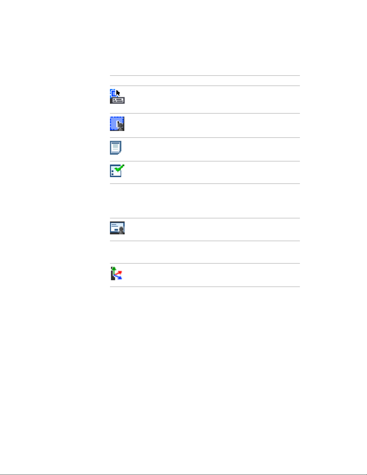
DescriptionAction Node NameIcon
Use Pick First Selection
tion)
Properties Palettes
Property
Object Filtering
Modal Dialog
View Change (Observation
Change)
The existing selection will be replaced by the
objects selected before the start of the playback for the action macro.
A request for a new selection.Request User Input (Selec-
Indicates that a change was made with the
Properties palette or Quick Properties panel.
Property change made with the Properties
palette or Quick Properties panel.
A selection with an object filter applied via
either the Properties palette or the Quick
Properties panel. Indicates which object filter
type was used.
A node that contains the recorded dialog box
that will be displayed during playback.
A view change occurred that was not explicitly
made by a command or coordinate change.
UCS Change
Quick Reference
Commands
ACTRECORD
Starts the Action Recorder.
UCS change that was not explicitly made by
a command or coordinate change.
Record an Action Macro | 35
Page 44

Work with User Interface Elements
Many of the common user interface elements can be used when recording an
action macro.
There are some elements that you cannot use. The following user interface
elements can be used when recording an action macro:
■ Toolbars and Quick Access toolbar
■ Pull-down menus and shortcut menus
■ Ribbon
■ Application menu
■ Legacy user interface elements (screen, icon, and tablet menus)
■ Application and drawing status bars
■ Properties palette and Quick Properties palette
■ Tool Palettes window
■ DesignCenter
User Interface Elements You Cannot Record
Not all actions preformed with the Properties palette and Quick Properties
palette are recorded. The following actions are not recorded:
■ Property changes made from a dialog box in the Properties palette or Quick
Properties palette.
■ Value changes made to the Vertex properties of 3D faces and polylines
with the Properties palette or Quick Properties palette.
■ Actions that do not execute a command from the status bars.
Not all actions preformed with the status bar are recorded. Only controls that
execute commands are recorded. The following buttons are recorded from
status bar:
■ Quick Properties
■ Model and layout
■ Quick View Layouts (limited to recording when layouts are switched)
36 | Chapter 1 Basic Customization
Page 45

■ Pan
■ Zoom
■ SteeringWheels
■ ShowMotion (limited to playing and restoring views)
■ Maximize/Minimize Viewport
■ Annotation/Viewport Scale
■ Synchronize Annotation/Viewport Scale
■ Annotation Visibility
■ Automatically Add Scales
■ Lock UI
■ Clean Screen
Not all actions performed in DesignCenter are recorded. The following actions
are not recorded:
■ Inserting blocks from the DC Online tab.
■ All actions from shortcut menus except Attach as Xref and Insert as Block.
■ Dragging named objects (such as layers and linetypes).
Quick Reference
Commands
ACTRECORD
Starts the Action Recorder.
Manage and Modify Action Macros
There are several methods for modifying and managing an action macro. You
can also edit and change the playback behavior of an action macro.
Manage and Modify Action Macros | 37
Page 46

Manage Action Macros
You can rename, copy, modify, and delete an action macro with the Action
Macro Manager or from the Action tree.
Modification and management of action macro file can be handled through
the Action Macro Manager and the Action tree.
Manage Files with the Action Tree
The Action tree is displayed when the Action Recorder panel is expanded. The
following options are available when you right-click the Action Macro in the
Action tree.
■ Rename. Renames the command and file name of the action macro.
■ Delete. Removes the action macro file from the Action Macro list and
places the file in the Windows Recycle Bin.
■ Copy. Creates a duplicate copy of the action macro; you specify a new
command and file name for the action macro.
■ Properties. Changes the command name and playback settings for the
action macro.
Action nodes that represent commands can be deleted and value nodes can
be edited. Action nodes in an action macro are modified through the Action
tree, which is displayed when the Action Recorder panel is expanded. The
following modify options are available when you right-click an action node
in the Action tree:
■ Delete. Removes an action node from the current action macro.
■ Edit. Replaces the current value with a new value.
Manage Action Macro Files
The Action Macro Manager dialog box performs basic file management
functionalities for your action macro (ACTM) files. You can modify, rename,
delete, and create multiple copies of an action macro file.
TIP You can select and delete a single or multiple copies of action macro files.
38 | Chapter 1 Basic Customization
Page 47

To rename an action macro
1 On the ribbon, click Manage tab ➤ Action Recorder panel. Click the
down arrow next to the Action Macro list.
2 In the Action Macro list, select the action macro you want to rename.
3 Expand the Action Recorder panel.
4 In the Action tree, right-click the top node and click Rename.
5 In the Action Macro dialog box, in the Action Macro Command Name
text box, enter a different name.
6 Click OK.
To delete a previously recorded action macro
1 On the ribbon, click Manage tab ➤ Action Recorder panel. Click the
down arrow next to the Action Macro list.
2 In the Action Macro list, select the action macro you want to delete.
3 Expand the Action Recorder panel.
4 In the Action Tree, right-click the top node and click Delete.
5 In the Action Macro - Confirm Deletion dialog box, click Delete.
NOTE When you delete an action macro, the file that the action macro was stored
in is also moved to the Windows Recycle Bin until deleted. If you might need the
file later, move the file from the Actions folder to a different folder.
To copy an action macro
1 On the ribbon, click Manage tab ➤ Action Recorder panel. Click the
down arrow next to the Action Macro list.
2 In the Action Macro list, select the action macro you want to copy.
3 Expand the Action Recorder panel.
4 In the Action tree, right-click the top node and click Copy.
5 In the Action Macro dialog box, in the Action Macro Command Name
text box, enter a different name and optionally do the following:
■ Enter a description for the action macro in the Description text box.
Manage and Modify Action Macros | 39
Page 48

■ Under Restore Pre-playback View, select When Pausing For User Input
to restore the view prior to the playback of the action macro.
■ Under Restore Pre-playback View, select Once Playback Finishes to
restore the view prior to the playback of the action macro.
■ Select Check for Inconsistencies when Playback Begins to have the
Action Recorder validate the action macro before playback.
6 Click OK.
To change the properties of an action macro
1 On the ribbon, click Manage tab ➤ Action Recorder panel. Click the
down arrow next to the Action Macro list.
2 In the Action Macro list, select the action macro for which you want to
change properties.
3 Expand the Action Recorder panel.
4 In the Action tree, right-click the top node and click Properties.
5 In the Action Macro dialog box, change the properties of the action macro
by doing the following:
■ Enter a command name for the action macro in the Action Macro
Command Name text box.
■ Enter a description for the action macro in the Description text box.
■ Under Restore Pre-playback View, select When Pausinf ForUser Input
to restore the view prior to the playback of the action macro.
■ Under Restore Pre-playback View, select Once Playback Finishes to
restore the view prior to the playback of the action macro.
■ Select Check for Inconsistencies when Playback Begins to have the
Action Recorder validate the action macro before playback.
6 Click OK.
To delete an action from an action macro
1 On the ribbon, click Manage tab ➤ Action Recorder panel. Click the
down arrow next to the Action Macro list.
40 | Chapter 1 Basic Customization
Page 49

2 In the Action Macro list, select the action macro from which you want
to delete an action.
3 Expand the Action Recorder panel.
4 In the Action tree, right-click an action node and click Delete.
5 In the Action Macro - Confirm Deletion of Item dialog box, click Delete.
NOTE You cannot delete an action while recording an action macro.
To edit a value node in an action macro
1 On the ribbon, click Manage tab ➤ Action Recorder panel. Click the
down arrow next to the Action Macro list.
2 In the Action Macro list, select the action macro in which you want to
edit a value node.
3 Expand the Action Recorder panel.
4 In the Action tree, right-click a value node and click Edit.
5 Enter the new value and press ENTER.
Quick Reference
Commands
ACTRECORD
Starts the Action Recorder.
RIBBON
Opens the ribbon window.
ACTMANAGER
Manages action macro files.
Insert User Messages
User messages can be inserted into an action macro to provide information
about or specific instructions for playing back an action macro.
Manage and Modify Action Macros | 41
Page 50

While recording an action macro, you can insert a user message into an action
macro that is displayed during playback. The message might be an overview
of what the action macro does, or settings that are needed before the action
macro is played back. You can insert as many user messages in an action macro
that you want; they can be inserted before or after any action in an action
macro.
When a message is displayed, click Close to continue with the playback of
the action macro.
To insert a user message into an action macro
1 On the ribbon, click Manage tab ➤ Action Recorder panel. Click the
down arrow next to the Action Macro list.
2 In the Action Macro list, select the action macro in which you want to
insert a user message.
3 Expand the Action Recorder panel.
4 In the Action tree, right-click a node and click Insert User Message.
NOTE You can only insert a user message before or after a node located
under the action macro node in the Action tree.
5 In the Insert User Message dialog box, enter the text message that you
want displayed when the action macro is played back.
6 Click OK.
To edit a user message inserted into an action macro
1 On the ribbon, click Manage tab ➤ Action Recorder panel. Click the
down arrow next to the Action Macro list.
2 In the Action Macro list, select the action macro whose user message you
want to edit.
3 Expand the Action Recorder panel.
4 In the Action tree, right-click the Text Message node and click Edit
Message.
5 In the Insert User Message dialog box, change the text message.
6 Click OK.
42 | Chapter 1 Basic Customization
Page 51

Quick Reference
Commands
ACTRECORD
Starts the Action Recorder.
ACTUSERMESSAGE
Pauses for user input in an action macro.
RIBBON
Opens the ribbon window.
Pause for User Input
Actions in an action macro can be modified to be played back with the values
they were recorded with or to pause for input during playback.
While recording an action macro, you might choose a point or provide input
that you do not want to use each time the action macro is played back. You
can toggle the behavior of a value node in the current action macro to pause
for input during playback. A value node might contain an acquired point,
text string, number, command option, or object selection. If an action macro
pauses for input, you can provide a new input value during playback.
To toggle the pause for input of a value during the playback of an action
macro.
1 On the ribbon, click Manage tab ➤ Action Recorder panel. Click the
down arrow next to the Action Macro list.
2 In the Action Macro list, select the action macro that contains the value
node that you want to pause for input during playback.
3 Expand the Action Recorder panel.
4 In the Action tree, right-click the value node and click Pause for User
Input.
Manage and Modify Action Macros | 43
Page 52

Quick Reference
Commands
ACTRECORD
Starts the Action Recorder.
ACTUSERINPUT
Inserts a user message into an action macro.
RIBBON
Opens the ribbon window.
Work with Coordinates
You can use absolute or relative coordinates for acquired points in an action
macro.
As you record an action macro, recorded coordinate values can be represented
as absolute or relative. While a coordinate value can be absolute or relative,
the stored value for all recorded coordinate values is absolute. Since all
coordinate values are stored as absolute with an action macro, you can toggle
between using the absolute or relative to previous point value for a recorded
coordinate value during playback. The first recorded coordinate value or
coordinate value after a UCS change is always defined as absolute. An absolute
coordinate value in an action macro is used as the base point for all later
relative coordinate values.
You can toggle the behavior of a coordinate value from the Action tree on the
Action Recorder. You can also change all coordinate values in an action macro
to be relative or absolute from the top node in the Action tree.
To toggle a coordinate value to be absolute or relative to the previous point
1 On the ribbon, click Manage tab ➤ Action Recorder panel. Click the
down arrow next to the Action Macro list.
2 In the Action Macro list, select the action macro that contains the
coordinate value node you want to modify.
3 Expand the Action Recorder panel.
44 | Chapter 1 Basic Customization
Page 53

4 In the Action tree, right-click the coordinate value node and click Relative
to Previous.
■ To make a coordinate value absolute, click Relative to Previous if a
check mark is present before it. If no check mark is present, then the
coordinate value is already absolute.
■ To make a coordinate value relative to the previous point, click Relative
to Previous if a check mark is not present before it. If a check mark is
present, then the coordinate value is already relative to the previous
point.
To toggle all coordinate values to be absolute or relative to the previous
point
1 On the ribbon, click Manage tab ➤ Action Recorder panel. Click the
down arrow next to the Action Macro list.
2 In the Action Macro list, select the action macro that contains the
coordinate value node that you want to be absolute or relative to the
previous coordinate.
3 Expand the Action Recorder panel.
4 In the Action tree, right-click the top node and click All Points Are
Relative.
■ To make all coordinate values absolute, click All Points Are Relative
if a check mark is present before it. If no check mark is present, then
the coordinate values might already be absolute; there might also be
a combination of absolute and relative coordinate values in the macro.
NOTE To be sure all coordinate values are absolute when All Points Are
Relative is not checked, select All Points Are Relative twice to avoid some
coordinate values being absolute while others are set relative to the
previous point.
■ To make all coordinate values relative to the previous point, except
for the first coordinate value, click Relative to Previous if a check mark
is not present before it. If a check mark is present, then all coordinate
values are already relative to the previous point with the exception
of the first coordinate value, which is always absolute.
Manage and Modify Action Macros | 45
Page 54

Quick Reference
Commands
ACTRECORD
Starts the Action Recorder.
RIBBON
Opens the ribbon window.
Insert Base Points
Inserting a base point establishes an absolute coordinate which is used by the
relative coordinate points that follow the base point in the action macro.
During the playback of an action macro, by default, a request to specify a new
coordinate point is made for each base point in the action macro.
In the Action tree, base points can be inserted on an action macro or command
node. You can insert base points at any time during recording. After recording,
you can insert or delete base points from an action macro.
NOTE In the Action tree, you can right-click a base point and disable Pause for
User Input. This eliminates the default behavior of the base point from requesting
a new coordinate point during playback.
To insert a base point into an action macro
1 On the ribbon, click Manage tab ➤ Action Recorder panel. Click the
down arrow next to the Action Macro list.
2 In the Action Macro list, select the action macro that you want to modify
by inserting a base point.
3 Expand the Action Recorder panel.
4 In the Action tree, right-click a node and click Insert Base Point.
5 Click OK.
46 | Chapter 1 Basic Customization
Page 55

Quick Reference
Commands
ACTRECORD
Starts the Action Recorder.
ACTBASEPOINT
Inserts a base point in an action macro.
RIBBON
Opens the ribbon window.
Work with Object Selections
Selection nodes are modified through the Action tree to control which objects
are used for the commands in an action macro.
When modifying an action macro, you can control the selection method to
use when playing back an action macro. You can use one of the following
options to alter the behavior of how objects are selected for the selection
results node in an action macro:
■ Use Pick First. Uses the objects selected prior to the start of the action
macro.
■ Pause for User Input. Prompts for a new selection set.
■ Use Macro-Created Object Selection. Selects all the objects that have been
created since the start of the action macro.
To pause for user input for a selection during playback
1 On the ribbon, click Manage tab ➤ Action Recorder panel. Click the
down arrow next to the Action Macro list.
2 In the Action Macro list, select the action macro that contains the
selection results node that you want to pause for user input during
playback.
3 Expand the Action Recorder panel.
4 In the Action tree, right-click the selection results to node and click Pause
for User Input.
Manage and Modify Action Macros | 47
Page 56

To toggle the use of macro-created selection during playback
1 On the ribbon, click Manage tab ➤ Action Recorder panel. Click the
down arrow next to the Action Macro list.
2 In the Action Macro list, select the action macro that contains the
selection results node that you want to represent a selection of all the
objects created during the macro playback.
3 Expand the Action Recorder panel.
4 In the Action tree, right-click the selection results node and click
Macro-created Object Selection.
To use Pick First selection during playback
1 On the ribbon, click Manage tab ➤ Action Recorder panel. Click the
down arrow next to the Action Macro list.
2 In the Action Macro list, select the action macro that contains the
selection results node that you want to represent the Pick First selection
of all the objects selected before a macro is played back.
3 Expand the Action Recorder panel.
4 In the Action tree, right-click the selection results node and click Use Pick
First Set.
Quick Reference
Commands
ACTRECORD
Starts the Action Recorder.
RIBBON
Opens the ribbon window.
Tips for Using the Action Recorder
The Action Recorder is designed to be intuitive and allow you to create custom
commands that can reduce the number of actions required to perform a
repetitive task. There are some things to consider when recording an action
macro.
48 | Chapter 1 Basic Customization
Page 57

Recording Action Macros
When recording an action macro, you should be aware of the following:
■ The current drawing settings used when recording an action macro are
not completely retained by an action macro. To make sure that specific
drawing settings are used during playback, record them as part of the action
macro using the system variable name or the SETVAR command.
■ While many commands are recorded, there are some commands that are
not recorded. The commands that are not recorded are related to drawing
file operations, working with the Action Recorder, and grip editing. The
following table lists the commands that are not recorded by the Action
Recorder.
ACTUSERINPUTACTSTOP
-ACTUSERMESSAGEACTUSERMESSAGE
EXPORTLAYOUTDXFIN
NEWFILEOPEN
PARTIALOPENOPEN
QNEWPRESSPULL
ACTMANAGER
TABLEDITRECOVER
-VBALOADVBAIDE
VBAMANVBALOAD
VBAPREFVBANEW
VBARUN-VBARUN
VBAUNLOADVBASTMT
ACTBASEPOINTXOPEN
Tips for Using the Action Recorder | 49
Page 58

■ Actions recorded with the Action Recorder are limited to interactions with
the Properties palette, Quick Properties palette, the Layer Modeless dialog
box, and any user interface element that starts a command.
Some of the user interface elements that start commands are: most tools
on tool palettes, some actions in DesignCenter, and some tools on the
status bars.
■ When a view change occurs, that is not explicitly made by a command or
coordinate change, (such as with the ViewCube, mouse wheel, or 3D Orbit),
a View Change (Observation Change) node is added to the Action tree.
You can delete a View Change node when recording is stopped. Upon
deletion, during playback, you might be prompted to provide input or
continue the playback because the view change did not occur. This might
affect the creation of a selection set or the use of a command.
NOTE Before deleting a View Change node, consider creating a copy of the
original macro file since you cannot undo the deletion of the node.
■ Changes to a dialog box are not recorded, but the dialog box is displayed
during playback. Instead of using a dialog box during recording, use the
command line version of the command to ensure that the action macro
behaves consistently each time it is played back.
■ Commands defined with AutoLISP and ObjectARX can be recorded with
an action macro, but the command must be loaded before the action macro
is played back. VBA macros and .NET assemblies can also be recorded as
part of an action macro, but they must be loaded in order to be played
back.
■ Action macros cannot have the same name as a command that is already
defined and loaded into AutoCAD.
■ The direction of an arc segment created with the Arc option of the PLINE
command is not played back correctly unless the Direction option is used
to define the arc segment.
■ While recording an action macro, you can record the current default value
displayed on the command line or use the default value that is current
when the action macro is played back. Pressing Enter without entering a
specific value during recording, displays a dialog box where you select to
use the current value during recording or the default value at playback.
■ While recording the TABLE command, the creation of the table is recorded
but any edits made to the cells of the table are not recorded.
50 | Chapter 1 Basic Customization
Page 59

Editing an Action Macro
When editing an action macro, the action macro files that are found in the
paths defined by the system variables ACTRECPATH and ACTPATHare loaded.
If more than one action macro file has the same name, the first action macro
file that is found is loaded into the Action Recorder. The other files with the
same names are ignored and not loaded.
To identify the path of a loaded action macro, select the action macro from
the Action Macros drop-down list and expand the Action Recorder panel.
Right-click the action macro’s node in the Action tree and click Properties. In
the Action Macro dialog box, the path to the action macro file is displayed in
the Folder Path text box.
Playing Back an Action Macro
When playing back an action macro, you should be aware of the following:
■ When playing back an action macro, the results of an action macro may
vary from those achieved when initially recording the action macro due
to differences between the drawing settings in the current drawing and
the one open when the action macro was recorded.
■ When playing back an action macro that displays a dialog box, the macro
will pause and wait until the dialog box is dismissed after changes are
made. If the dialog box is canceled, the macro will continue to play back
but the results may differ from those expected.
■ When playing back an action macro that contains commands defined with
AutoLISP, ObjectARX, or .NET assemblies, playback of the action macro
will fail if the files that define the commands are not loaded. If an action
macro references a VBA macro, the playback of the action macro will fail
if the project file is not loaded.
Exchanging Action Macros
When exchanging action macros with others, you should be aware of the
following:
■ Action macros recorded with one of the AutoCAD based vertical products
may not play back correctly based on the commands that were used when
the action macro was recorded.
■ Action macros may not play back correctly when recorded in one language
of AutoCAD and then played back with a different language of AutoCAD.
Tips for Using the Action Recorder | 51
Page 60

Quick Reference
Commands
ACTRECORD
Starts the Action Recorder.
RIBBON
Opens the ribbon window.
Examples of Action Macros
The following examples show some of the ways that action macros can
automate repetitive tasks. The examples shows some of the different ways that
you can record actions with the Action Recorder.
Create a New Layer and Draw Objects
In this example, you create an action macro that makes a new layer and then
draws objects on the layer to create a two-dimensional top view of a hexagon
bolt.
In this example, you learn how to
■ Record and save an action macro
■ Record commands and input values to create and modify a new layer
■ Record commands and input values to create and modify objects
■ Insert a user message
■ Insert base point
■ Pause for user input
■ Play back an action macro
Start Recording an Action Macro
You start recording actions in the Action Recorder panel. To display the Action
Recorder panel and start recording, follow these steps:
1 On the ribbon, click the Manage tab.
52 | Chapter 1 Basic Customization
Page 61

2 On the Action Recorder panel, click Record.
Record commands and input values to create and modify a new layer
Once the Action Recorder starts recording, you use the Layer Properties
Manager to create a new layer. Follow these steps:
1 At the Command prompt, enter -layer and press Enter.
2 At the prompt, Enter an option
[?/Make/Set/New/Rename/ON/OFF/Color/Ltype/LWeight/MATerial/Plot/Freeze/Thaw/LOck/Unlock/stAte/Description/rEconcile],
enter m and press Enter.
3 At the prompt, Enter name for new layer (becomes the current layer) <0>,
enter Bolt and press Enter.
4 At the prompt, Enter an option
[?/Make/Set/New/Rename/ON/OFF/Color/Ltype/LWeight/MATerial/Plot/Freeze/Thaw/LOck/Unlock/stAte/Description/rEconcile],
enter c and press Enter.
5 At the prompt, New color [Truecolor/COlorbook], enter 1 and press Enter.
6 At the prompt, Enter name list of layer(s) for color 1 (red) <Bolt>, press
Enter to assign the color Red to the Bolt layer.
If the Action Macro - Value Not Recorded dialog box is displayed, click
the Use the Value that is Current at Playback link. This will assign the
color specified to the to the recent layer that was created with the Make
option.
7 Press Enter again to exit the -LAYER command.
Record Commands and Input Values Used to Create and Modify Objects
Creating the Bolt layer has been recorded. Next, you create a circle and then
a six sided polygon based on the center of the circle for a hexagon bolt. Once
the circle and polygon are drawn, you use the SCALE command to control
the size of the hexagon bolt when the action macro is played back. Follow
these steps:
1 At the Command prompt, enter circle and press Enter.
2 At the prompt, Specify center point for circle or [3P/2P/Ttr (tan tan
radius)], click in the drawing window.
3 At the prompt, Specify radius of circle or [Diameter], enter 0.9 and press
ENTER.
Examples of Action Macros | 53
Page 62

4 At the Command prompt, enter polygon and press Enter.
5 At the prompt, Enter number of sides <4>, enter 6 and press Enter.
6 At the prompt, Specify center of polygon or [Edge], use the Center object
snap and select the edge of the circle.
7 At the prompt, Enter an option [Inscribed in circle/Circumscribed about
circle] <C>, enter c and press Enter.
8 At the prompt, Specify radius of circle, enter 1 and press Enter.
9 At the Command prompt, enter scale and press Enter.
10 At the prompt, Select objects, select both the circle and polygon and press
Enter.
11 At the prompt, Specify base point, use the Center object snap and select
the edge of the circle.
12 At the prompt, Specify scale factor or [Copy/Reference] <1.0000>, enter
1 and press Enter.
Stop Recording and Save an Action Macro
After all the actions have been recorded, you stop recording and save the
recorded actions to an action macro file. Follow these steps:
1 On the Action Recorder panel, click Stop.
2 In the Action Macro dialog box, do the following:
■ In the Action Macro Command Name box, enter CreateBolt.
■ In the Description box, enter Creates a hexagon bolt.
3 Click OK.
Insert a User Message
With a user message, you can provide instructions or general information
about the action macro to the user before any changes are made to the drawing
during playback. To insert a user message in the action macro, follow these
steps:
1 On the Action Recorder panel, click the title bar to expand the panel.
2 In the Action tree, select the CreateBolt node and right-click. Click Insert
User Message.
54 | Chapter 1 Basic Customization
Page 63

3 In the Insert User Message dialog box, enter Creates a hexagon bolt by
drawing a circle and polygon. During playback you are prompted for the
center point of the circle and size of the bolt. Click OK.
Insert a Base Point
With insert a base point, you are prompted to specify a base point when
playing back an action macro. In this action macro, you specify a base point
used for the center point of the circle during playback. Follow these steps:
1 On the Action Recorder panel, click the title bar to expand the panel.
2 In the Action tree, select the Circle action node and right-click. Click
Insert Base Point.
Pause for User Input
With a pause for user input, you are prompted to enter a value when playing
back an action macro. In this action macro, you change the scale factor for
the SCALE command to pause for user input during play back. Follow these
steps:
1 On the Action Recorder panel, click the title bar to expand the panel.
2 Select the Scale Factor value node under the Scale action node and
right-click. Click Pause for User Input.
Play Back the Action Macro
When you play back the action macro, you are prompted to specify a base
point of a circle and the scale factor for the SCALE command. To see the results
of the action macro, follow these steps:
1 On the Action Recorder panel, on the Action Macro list, select CreateBolt.
2 Click Play.
3 In the User Message dialog box, click Close.
4 When prompted to specify a base point, click a coordinate point in the
drawing window.
5 The circle and polygon are drawn.
6 When prompted for a scale factor, enter a numeric value (such as 1 or
0.25) at the Command prompt and press Enter.
The circle and polygon are scaled based on the scale factor entered.
Examples of Action Macros | 55
Page 64

7 In the Action Macro - Playback Complete dialog box, click OK.
Quick Reference
Commands
ACTRECORD
Starts the Action Recorder.
ACTSTOP
Stops the Action Recorder and provides the option of saving the recorded
actions to an action macro file.
ACTUSERINPUT
Pauses for user input in an action macro.
ACTUSERMESSAGE
Inserts a user message into an action macro.
ACTBASEPOINT
Inserts a base point in an action macro.
CIRCLE
Creates a circle.
LAYER
Manages layers and layer properties.
POLYGON
Creates an equilateral closed polyline.
RIBBON
Opens the ribbon window.
SCALE
Enlarges or reduces selected objects, keeping the proportions of the object
the same after scaling.
56 | Chapter 1 Basic Customization
Page 65

Insert a Block and Change a Dynamic Property Value
This example shows how to insert a dynamic block from a tool palette and
change its dynamic properties using the Properties palette.
In this example, you learn how to
■ Record and save an action macro
■ Record actions from the Tool Palettes window
■ Modify an object using the Properties palette
■ Remove action nodes from an action macro
■ Insert Base Point
■ Play back an action macro
Start Recording an Action Macro
You start recording actions on the Action Recorder panel. To display the Action
Recorder panel and to start recording, follow these steps:
1 On the ribbon, click the Manage tab.
2 On the Action Recorder panel, click Record.
Record Actions from the Tool Palettes Window
You can use tools from a tool palette and then play back the action that is
performed by a tool. From the Tool Palettes window, you will place the I Beam
- Imperial dynamic block from the Structural tool palette. Follow these steps:
1 At the Command prompt, enter toolpalettes to display the Tool Palettes
window.
2 At the Command prompt, enter properties to display the Properties
palette.
3 In the Tool Palettes window, under the All Palettes group, click the
Structural tab.
4 On the Structural tab, click the I Beam - Imperial tool.
5 On the Properties palette, under the Custom category, click the Beam
Sizes field.
6 On the Beam Sizes drop-down list, select IPE A 140.
Examples of Action Macros | 57
Page 66

7 In the drawing window, specify the insertion point for the block.
Stop Recording and Save an Action Macro
After all the actions have been recorded, you stop recording and save the
recorded actions to an action macro file. Follow these steps:
1 On the Action Recorder panel, click Stop.
2 In the Action Macro dialog box, do the following
■ In the Action Macro Command Name box, enter InsertIPEA140.
■ In the Description box, enter Inserts an IPE A 140 beam.
3 Click OK.
Remove Action Nodes
When you record an action macro, at times additional actions are recorded
that you do not need. For example, while recording the action macro you
displayed the Tool Palettes window and the Properties palette. Those action
nodes are not needed in order to play back the action macro. To remove action
nodes from the action macro, follow these steps:
1 On the Action Recorder panel, click the title bar to expand the panel.
2 In the Action tree, select the TOOLPALETTES action node under the
Action Macro node and right-click. Click Delete.
3 Select the Properties action node and right-click. Click Delete.
Play Back the Action Macro
When you play back the action macro, you are prompted to specify the
insertion point of the block. To see the results of the action macro, follow
these steps:
1 On the Action Recorder panel, on the Action Macro list, select
InsertIPEA140.
2 Click Play.
3 When prompted to specify a base point, click a base point in the drawing
window to insert the block.
As the block is inserted, the beam size selected on the Properties palette
is reflected on-screen.
58 | Chapter 1 Basic Customization
Page 67

4 In the Action Macro - Playback Complete dialog box, click OK.
Quick Reference
Commands
ACTRECORD
Starts the Action Recorder.
ACTSTOP
Stops the Action Recorder and provides the option of saving the recorded
actions to an action macro file.
PROPERTIES
Controls properties of existing objects.
RIBBON
Opens the ribbon window.
TOOLPALETTES
Opens the Tool Palettes window.
Modify Circles with the Properties Palette
This example shows how to apply an object filter to select objects and then
change the color property of the selected objects.
In this example, you learn how to
■ Record and save an action macro
■ Modify an object using the Properties palette
■ Select objects and use an object selection filter
■ Use Pick First selection
■ Play back an action macro
Start Recording an Action Macro
You start recording actions on the Action Recorder panel. To display the Action
Recorder panel and to start recording, follow these steps:
Examples of Action Macros | 59
Page 68

1 On the ribbon, click the Manage tab.
2 On the Action recorder panel, click Record.
Modify Objects Using the Properties Palette and Object Selection Filter
When working with the Properties palette, you can control which objects you
modify by applying an object selection filter to the selected objects. Follow
these steps:
1 Select the objects in the drawing that you want to modify and right-click.
Click Properties.
2 On the Properties palette, in the Objects drop-down list, select Circles.
3 Under the General category, select the Color field.
4 In the Color drop-down list, select Blue.
Stop Recording and Save an Action Macro
After all the actions have been recorded, you stop recording and save the
recorded actions to an action macro file. Follow these steps:
1 On the Action Recorder panel, click Stop.
2 In the Action Macro dialog box, do the following
■ In the Action Macro Command Name box, enter BlueCircles.
■ In the Description box, enter Changes the color of all selected circles
to blue.
3 Click OK.
Change the Selection Set to Use the Pick First Selection Set
With a request for user input, you are prompted for a value to be entered
instead of using a recorded value when playing back an action macro. In this
action macro, you change the selection set created to use the Pick First
selection. Follow these steps:
1 On the Action Recorder panel, click the title bar to expand the panel.
2 In the Action tree, under the Action Macro node, select the Pickfirst value
node and right-click. Click Use Pick First Set.
60 | Chapter 1 Basic Customization
Page 69

Play Back the Action Macro
When you play back the action macro, you are prompted to select objects if
no objects are selected. To see the results of the action macro, follow these
steps:
1 Draw some circles and other objects in the drawing. Change the colors
of the objects to colors other than blue.
2 On the Action Recorder panel, on the Action Macro list, select BlueCircles.
3 Click Play.
4 In the Action Macro - No Objects Selected dialog box, click Select Objects
and Continue.
5 When prompted to select objects, select the circles and the other objects
in the drawing. Press ENTER to complete object selection.
The circles in the selection set are changed to the color blue.
6 If the Action Macro - Playback Complete dialog box is displayed, click
OK.
Undo the changes made by the action macro by clicking Undo from the Quick
Access toolbar. Now select some objects in the drawing and playback the
BlueCircles action macro. This time the action macro uses the Pick First
selection and you are not prompted to select the objects in the drawing when
the action macro is played back.
Quick Reference
Commands
ACTRECORD
Starts the Action Recorder.
ACTSTOP
Stops the Action Recorder and provides the option of saving the recorded
actions to an action macro file.
PROPERTIES
Controls properties of existing objects.
RIBBON
Opens the ribbon window.
Examples of Action Macros | 61
Page 70

System Variables
PICKFIRST
Controls whether you select objects before (noun-verb selection) or after you
issue a command.
62 | Chapter 1 Basic Customization
Page 71

Custom Linetypes
2
AutoCAD® provides a library of standard linetypes in the acad.lin and acadiso.lin files. You can
use the linetypes as they are, modify them, or create your own custom linetypes.
Overview of Linetype Definitions
Linetypes are defined in one or more linetype definition files that have a .lin
file extension.
The linetype name and definition determine the particular dash-dot sequence,
the relative lengths of dashes and blank spaces, and the characteristics of any
included text or shapes. You can use any of the standard linetypes that AutoCAD
provides, or you can create your own linetypes.
examples of linetypes
A LIN file can contain definitions of many simple and complex linetypes. You
can add new linetypes to an existing LIN file, or you can create your own LIN
file. To create or modify linetype definitions, edit the LIN file using a text editor
or word processor or use LINETYPE at the command prompt.
When you create a linetype, you must load the linetype before you can use it.
The LIN files included in AutoCAD are acad.lin and acadiso.lin. You can display
or print these text files to better understand how to construct linetypes.
63
Page 72

Quick Reference
Commands
LINETYPE
Loads, sets, and modifies linetypes.
System Variables
MEASUREINIT
Controls whether a drawing you start from scratch uses imperial or metric
default settings.
Simple Custom Linetypes
Each linetype is defined on two lines in a linetype definition file. The first
line contains the linetype name and an optional description. The second line
is the code that defines the actual linetype pattern.
The second line must begin with the letter A (alignment), followed by a list
of pattern descriptors that define pen-up lengths (spaces), pen-down lengths
(dashes), and dots. You can include comments in an LIN file by beginning
the line with a semicolon (;).
Linetype Definition Format
The format of the linetype definition is
*linetype_name,description
A,descriptor1,descriptor2, ...
For example, a linetype called DASHDOT is defined as
*DASHDOT,Dash dot __ . __ . __ . __ . __ . __ . __ . __
A,.5,-.25,0,-.25
This indicates a repeating pattern starting with a dash 0.5 drawing units long,
a space 0.25 drawing units long, a dot, and another space 0.25 drawing units
long. This pattern continues for the length of the line, ending with a dash 0.5
drawing units long. The linetype would be displayed as shown below.
__ . __ . __ . __ . __ . __ . __ . __
LIN files must be saved in ASCII format and use an .lin file extension. Additional
information about each field in a linetype definition follows.
64 | Chapter 2 Custom Linetypes
Page 73

Linetype Name
The linetype name field begins with an asterisk (*) and should provide a
unique, descriptive name for the linetype.
Description
The description of the linetype should help you visualize the linetype when
you edit the LIN file. The description is also displayed in the Linetype Manager
and in the Load or Reload Linetypes dialog box.
The description is optional and can include
■ A simple representation of the linetype pattern using ASCII text
■ An expanded description of the linetype
■ A comment such as "Use this linetype for hidden lines"
If you omit the description, do not insert a comma after the linetype name.
A description cannot exceed 47 characters.
Alignment Field (A)
The alignment field specifies the action for pattern alignment at the ends of
individual lines, circles, and arcs. Currently, AutoCAD supports only A-type
alignment, which guarantees that the endpoints of lines and arcs start and
stop with a dash.
For example, suppose you create a linetype called CENTRAL that displays the
repeating dash-dot sequence commonly used as a centerline. AutoCAD adjusts
the dash-dot sequence on an individual line so that dashes and line endpoints
coincide. The pattern fits the line so that at least half of the first dash begins
and ends the line. If necessary, the first and last dashes are lengthened. If a
line is too short to hold even one dash-dot sequence, AutoCAD draws a
continuous line between the endpoints. For arcs also, the pattern is adjusted
so that dashes are drawn at the endpoints. Circles do not have endpoints, but
AutoCAD adjusts the dash-dot sequence to provide a reasonable display.
You must specify A-type alignment by entering a in the alignment field.
Simple Custom Linetypes | 65
Page 74

Pattern Descriptors
Each pattern descriptor field specifies the length of segments making up the
linetype, separated by commas (no spaces are allowed):
■ A positive decimal number denotes a pen-down (dash) segment of that
length.
■ A negative decimal number denotes a pen-up (space) segment of that
length.
■ A dash length of 0 draws a dot.
You can enter up to 12 dash-length specifications per linetype, provided they
fit on one 80-character line in the LIN file. You need to include only one
complete repetition of the linetype pattern defined by pattern descriptors.
When the linetype is drawn, AutoCAD uses the first pattern descriptor for the
starting and ending dashes. Between the starting and ending dashes, the
pattern dash specifications are drawn sequentially, beginning with the second
dash specification and restarting the pattern with the first dash specification
when required.
A-type alignment requires that the first dash length be 0 or greater (a pen-down
segment). The second dash length should be less than 0 if you need a pen-up
segment and more than 0 if you are creating a continuous linetype. You must
have at least two dash specifications for A-type alignment.
To create a simple linetype from the Command prompt
1 At the command prompt, enter -linetype.
2 Enter c (Create).
3 Enter a name for the linetype and press ENTER.
The linetype name can include up to 255 characters. Linetype names can
contain letters, digits, and the special characters dollar sign ($), hyphen
(-), and underscore (_). Linetype names cannot include blank spaces.
4 In the Create or Append Linetype File dialog box, select an LIN linetype
library file from the File Name box and choose Save.
If you select an existing file, the new linetype name is added to the
linetype names in the file.
5 Enter text that describes the new linetype (optional).
66 | Chapter 2 Custom Linetypes
Page 75

6 At the Enter Pattern prompt, specify the pattern of the line. Follow these
guidelines:
■ All linetypes must begin with a dash.
■ Enter zeros for dots.
■ Enter negative real numbers for spaces. The value defines the length
of the space in drawing units.
■ Enter positive real numbers for dashes. The value defines the length
of the dash in drawing units.
■ Separate each dot, dash, or space value from the next with a comma.
■ Use a space between a dot and a dash.
7 Press ENTER to end the command.
NOTE When you create a linetype, it is not loaded into your drawing automatically.
Use the Load option of LINETYPE.
To add a simple linetype to a LIN file
1 Open the acad.lin or acadiso.lin file in a text editor that saves in ASCII
format (for example, Notepad).
2 Create a header line that includes an asterisk and a linetype pattern name.
The name of the linetype pattern is limited to 31 characters.
3 (Optional) To include a description in the header line, follow the linetype
pattern name with a comma and description text.
4 Create a descriptor line that includes:
■ All linetypes must begin with a dash.
■ Enter zeros for dots.
■ Enter negative real numbers for spaces. The value defines the length
of the space in drawing units.
■ Enter positive real numbers for dashes. The value defines the length
of the dash in drawing units.
■ Separate each dot, dash, or space value from the next with a comma.
■ Use a space between a dot and a dash.
Simple Custom Linetypes | 67
Page 76

Quick Reference
Commands
LINETYPE
Loads, sets, and modifies linetypes.
System Variables
MEASUREINIT
Controls whether a drawing you start from scratch uses imperial or metric
default settings.
Text in Custom Linetypes
Characters from text fonts can be included in linetypes.
Characters from text fonts can be included in linetypes. Linetypes with
embedded characters can denote utilities, boundaries, contours, and so on.
As with simple linetypes, lines are dynamically drawn as you specify the
vertices. Characters embedded in lines are always displayed completely; they
are never trimmed.
Embedded text characters are associated with a text style in the drawing. Any
text styles associated with a linetype must exist in the drawing before you
load the linetype.
The format for linetypes that include embedded characters is similar to that
for simple linetypes in that it is a list of pattern descriptors separated by
commas.
Character Descriptor Format
The format for adding text characters in a linetype description is as follows:
["text",textstylename,scale,rotation,xoffset,yoffset]
This format is added as a descriptor to a simple linetype. For example, a
linetype called HOT_WATER_SUPPLY is defined as
*HOT_WATER_SUPPLY,---- HW ---- HW ---- HW ---- HW ---- HW ---A,.5,-.2,["HW",STANDARD,S=.1,U=0.0,X=-0.1,Y=-.05],-.2
This indicates a repeating pattern starting with a dash 0.5 drawing units long,
a space 0.2 drawing units long, the characters HW with some scale and
placement parameters, and another space 0.2 drawing units long. The text
68 | Chapter 2 Custom Linetypes
Page 77

characters come from the text font assigned to the STANDARD text style at a
scale of 0.1, an upright rotation of 0 degrees, an X offset of -0.1, and a Y offset
of -0.05. This pattern continues for the length of the line, ending with a dash
0.5 drawing units long. The linetype would be displayed as shown below.
Notice that the total upstroke length is 0.2 + 0.2 = 0.4 and that the text origin
is offset -.01 units in the X direction from the end of the first upstroke. An
equivalent linetype would be
*HOT_WATER_SUPPLY,---- HW ---- HW ---- HW ---- HW ---- HW ---A,.5,-.1,["HW",STANDARD,S=.1,U=0.0,X=0.0,Y=-.05],-.3
The total upstroke is still 0.1 + 0.3 = 0.4, but the text origin is not offset in the
X direction.
Additional information about each field in the character descriptor follows.
The values to be used are signed decimal numbers such as 1, -17, and 0.01.
text The characters to be used in the linetype.
text style name The name of the text style to be used. If no text style is
specified, AutoCAD uses the currently defined style.
scale S=value. The scale factor to be used for the text style relative to the scale
of the linetype. The height of the text style is multiplied by the scale factor.
If the height is 0, the value for S=value alone is used as the height.
rotation U=value, R=value, or A=value. U= specifies upright or easy-to-read
text. R= specifies relative or tangential rotation with respect to the line. A=
specifies absolute rotation of the text with respect to the origin; that is, all
text has the same rotation regardless of its position relative to the line. The
value can be appended with a d for degrees (degrees is the default value), r for
radians, or g for grads. If rotation is omitted, 0 relative rotation is used.
Rotation is centered between the baseline and the nominal cap height.
Text in Custom Linetypes | 69
Page 78

NOTE Drawings containing legacy linetypes that do not use the U (upright)
rotation flag can be updated to the latest linetype definition by reloading the
linetype from the LIN files. Custom linetypes can be updated by changing the R
(rotation) flag to the U (upright) flag prior to reloading a linetype definition. For
information on loading a linetype, see Load Linetypes.
xoffset X=value. The shift of the text on the X axis of the linetype, which is
along the line. If xoffset is omitted or is 0, the text is elaborated with no
offset. Use this field to control the distance between the text and the previous
pen-up or pen-down stroke. This value is not scaled by the scale factor defined
by S=value, but it is scaled to the linetype.
yoffset Y=value. The shift of the text in the Y axis of the linetype, which is at
a 90-degree angle to the line. If yoffset is omitted or is 0, the text is elaborated
with no offset. Use this field to control the vertical alignment of the text with
respect to the line. This value is not scaled by the scale factor defined by
S=value, but it is scaled to the linetype.
To include text characters in linetypes
1 Create a simple linetype, as described in To add a simple linetype to a
LIN file on page 67.
2 Add the text character descriptor within the linetype pattern, using the
following format:
["text",textstylename,scale,rotation,xoffset,yoffset]
Quick Reference
Commands
LINETYPE
Loads, sets, and modifies linetypes.
System Variables
MEASUREINIT
Controls whether a drawing you start from scratch uses imperial or metric
default settings.
70 | Chapter 2 Custom Linetypes
Page 79

Shapes in Custom Linetypes
A complex linetype can contain embedded shapes that are saved in shape
files. Complex linetypes can denote utilities, boundaries, contours, and so on.
As with simple linetypes, complex lines are dynamically drawn as the user
specifies vertices. Shapes and text objects embedded in lines are always
displayed completely; they are never trimmed.
The syntax for complex linetypes is similar to that of simple linetypes in that
it is a comma-delimited list of pattern descriptors. Complex linetypes can
include shape and text objects as pattern descriptors, as well as dash-dot
descriptors.
The syntax for shape object descriptors in a linetype description is as follows:
[shapename,shxfilename] or [shapename,shxfilename,transform]
where transform is optional and can be any series of the following (each
preceded by a comma):
R=## Relative rotation
A=## Absolute rotation
S=## Scale
X=## X offset
Y=## Y offset
In this syntax, ## is a signed decimal number (1, -17, 0.01, and so on), the
rotation is in degrees, and the remaining options are in linetype-scaled drawing
units. The preceding transform letters, if they are used, must be followed by
an equal sign and a number.
The following linetype definition defines a linetype named CON1LINE that
is composed of a repeating pattern of a line segment, a space, and the
embedded shape CON1 from the ep.shx file. (Note that the ep.shx file must be
in the support path for the following example to work properly.)
*CON1LINE, --- [CON1] --- [CON1] --- [CON1]
A,1.0,-0.25,[CON1,ep.shx],-1.0
Except for the code enclosed in square brackets, everything is consistent with
the definition of a simple linetype.
As previously described, a total of six fields can be used to define a shape as
part of a linetype. The first two are mandatory and position-dependent; the
Shapes in Custom Linetypes | 71
Page 80

next four are optional and can be ordered arbitrarily. The following two
examples demonstrate various entries in the shape definition field.
[CAP,ep.shx,S=2,R=10,X=0.5]
The code above draws the CAP shape defined in the ep.shx shape file with a
scale of two times the unit scale of the linetype, a tangential rotation of 10
degrees in a counterclockwise direction, and an X offset of 0.5 drawing units
before shape elaboration takes place.
[DIP8,pd.shx,X=0.5,Y=1,R=0,S=1]
The code above draws the DIP8 shape defined in the pd.shx shape file with an
X offset of 0.5 drawing units before shape drawing takes place, and a Y offset
of one drawing unit above the linetype, with 0 rotation and a scale equal to
the unit scale of the linetype.
The following syntax defines a shape as part of a complex linetype.
[shapename,shapefilename,scale,rotate,xoffset,yoffset]
The definitions of the fields in the syntax follow.
shapename The name of the shape to be drawn. This field must be included.
If it is omitted, linetype definition fails. If shapename does not exist in the
specified shape file, continue drawing the linetype but without the embedded
shape.
shapefilename The name of a compiled shape definition file (SHX). If it is
omitted, linetype definition fails. If shapefilename is unqualified (that is, no
path is specified), search the library path for the file. If shapefilename is fully
qualified and not found at that location, remove the prefix and search the
library path for the file. If it is not found, continue drawing the linetype but
without the embedded shape.
scale S=value. The scale of the shape is used as a scale factor by which the
shape's internally defined scale is multiplied. If the shape's internally defined
scale is 0, the S=value alone is used as the scale.
rotate R=value or A=value. R= signifies relative or tangential rotation with
respect to the line's elaboration. A= signifies absolute rotation of the shape
with respect to the origin; all shapes have the same rotation regardless of their
relative position to the line. The value can be appended with a d for degrees
(if omitted, degree is the default), r for radians, or g for grads. If rotation is
omitted, 0 relative rotation is used.
xoffset X=value. The shift of the shape in the X axis of the linetype computed
from the end of the linetype definition vertex. If xoffset is omitted or is 0,
72 | Chapter 2 Custom Linetypes
Page 81

the shape is elaborated with no offset. Include this field if you want a
continuous line with shapes. This value is not scaled by the scale factor defined
by S=.
yoffset Y=value. The shift of the shape in the Y axis of the linetype computed
from the end of the linetype definition vertex. If yoffset is omitted or 0, the
shape is elaborated with no offset. This value is not scaled by the scale factor
defined by S=.
See also:
■ Shapes and Shape Fonts on page 453
Quick Reference
Commands
LINETYPE
Loads, sets, and modifies linetypes.
SHAPE
Inserts a shape from a shape file that has been loaded using LOAD.
System Variables
MEASUREINIT
Controls whether a drawing you start from scratch uses imperial or metric
default settings.
Shapes in Custom Linetypes | 73
Page 82

74
Page 83

Custom Hatch Patterns
3
AutoCAD® provides a library of standard hatch patterns in the acad.pat and acadiso.pat files.
You can use the hatch patterns as they are, modify them, or create your own custom hatch
patterns.
Overview of Hatch Pattern Definitions
In addition to using the predefined hatch patterns that are supplied, you can
design and create your own custom hatch patterns.
In addition to using the predefined hatch patterns that are supplied, you can
design and create your own custom hatch patterns. Developing a hatch pattern
definition requires knowledge, practice, and patience. Because customizing
hatches requires familiarity with hatch patterns, it is not recommended for new
users.
The hatch patterns supplied by AutoCAD are stored in the acad.pat and
acadiso.pat text files. You can add hatch pattern definitions to this file or create
your own files.
Regardless of where the definition is stored, a custom hatch pattern has the
same format. It has a header line with a name, which begins with an asterisk
and is no more than 31 characters long, and an optional description:
*pattern-name, description
It also has one or more line descriptors of the following form:
angle, x-origin,y-origin, delta-x,delta-y,dash-1,dash-2, …
The default hatch pattern ANSI31 shown in the Boundary Hatch and Fill dialog
box looks like this:
75
Page 84

and is defined as follows:
*ANSI31, ANSI Iron, Brick, Stone masonry
45, 0,0, 0,.125
The pattern name on the first line, *ANSI31, is followed by a description: ANSI
Iron, Brick, Stone masonry. This simple pattern definition specifies a line
drawn at an angle of 45 degrees, that the first line of the family of hatch lines
is to pass through the drawing origin (0,0), and that the spacing between
hatch lines of the family is to be 0.125 drawing units.
Hatch pattern definitions follow these rules:
■ Each line in a pattern definition can contain up to 80 characters. You can
include letters, numbers, and the special characters underline (_), hyphen
(-), and dollar sign ($). However, you must begin a pattern definition with
a letter or number, not a special character.
■ AutoCAD ignores both blank lines and text to the right of a semicolon.
■ Each pattern line is considered to be the first member of a line family,
created by applying the delta offsets in both directions to generate an
infinite family of parallel lines.
■ The delta-x value indicates the displacement between members of the
family in the direction of the line. It is used only for dashed lines.
■ The delta-y value indicates the spacing between members of the family;
that is, it is measured perpendicular to the lines.
■ A line is considered to be of infinite length. A dash pattern is superimposed
on the line.
NOTE A blank line must be placed after the last hatch pattern definition in a PAT
file. If a blank line is not placed after the last hatch pattern definition, the last hatch
pattern definition will not be accessible when creating a hatch fill.
The process of hatching consists of expanding each line in the pattern
definition to its infinite family of parallel lines. All selected objects are checked
for intersections with any of these lines; any intersections cause the hatch
lines to be turned on and off as governed by the hatching style. Each family
76 | Chapter 3 Custom Hatch Patterns
Page 85

of hatch lines is generated parallel to an initial line with an absolute origin
to guarantee proper alignment.
If you create a very dense hatch, AutoCAD may reject the hatch and display
a message indicating that the hatch scale is too small or its dash length too
short. You can change the maximum number of hatch lines by setting the
MaxHatch system registry variable using (setenv “MaxHatch” “n”) where n is
a number between 100 and 10000000 (ten million).
NOTE When changing the value of MaxHatch, you must enter MaxHatch with
the capitalization as shown.
To create a simple hatch pattern
1 Open the acad.pat or acadiso.pat file in a text editor that saves in ASCII
format (for example, Microsoft® Windows® Notepad).
2 Create a header line that includes an asterisk and a pattern name. The
name of the hatch pattern is limited to 31 characters.
3 (Optional) To include a description in the header line, follow the pattern
name with a comma and description text.
4 Create a descriptor line that includes
■ An angle at which the line is drawn
■ An X,Y origin point
■ A delta-x of 0
■ A delta-y of any value
Quick Reference
Commands
ADCENTER
Manages and inserts content such as blocks, xrefs, and hatch patterns.
FILL
Controls the filling of objects such as hatches, 2D solids, and wide polylines.
Overview of Hatch Pattern Definitions | 77
Page 86

HATCH
Fills an enclosed area or selected objects with a hatch pattern, solid fill, or
gradient fill.
HATCHEDIT
Modifies an existing hatch or fill.
SOLID
Creates solid-filled triangles and quadrilaterals.
System Variables
FILLMODE
Specifies whether hatches and fills, 2D solids, and wide polylines are filled
in.
HPANG
Sets the angle for new hatch patterns.
HPBOUND
Controls the object type created by HATCH and BOUNDARY.
HPDOUBLE
Specifies hatch pattern doubling for user-defined patterns.
HPNAME
Sets the default hatch pattern name.
HPSCALE
Sets the hatch pattern scale factor.
HPSPACE
Sets the hatch pattern line spacing for user-defined patterns.
Hatch Patterns with Dashed Lines
To define dashed-line patterns, you append dash-length items to the end of
the line definition item.
To define dashed-line patterns, you append dash-length items to the end of
the line definition item. Each dash-length item specifies the length of a
segment making up the line. If the length is positive, a pen-down segment is
78 | Chapter 3 Custom Hatch Patterns
Page 87

drawn. If the length is negative, the segment is pen-up, and it is not drawn.
The pattern starts at the origin point with the first segment and cycles through
the segments in circular fashion. A dash length of 0 draws a dot. You can
specify up to six dash lengths per pattern line.
The hatch pattern ANSI33, shown in the Boundary Hatch and Fill dialog box,
looks like this:
and is defined as follows:
*ANSI33, ANSI Bronze, Brass, Copper
45, .176776695,0, 0,.25, .125,-.0625
For example, to modify a pattern for 45-degree lines to draw dashed lines with
a dash length of 0.5 units and a space between dashes of 0.5 units, the line
definition would be
*DASH45, Dashed lines at 45 degrees
45, 0,0, 0,.5, .5,-.5
This is the same as the 45-degree pattern shown in Overview of Hatch Pattern
Definitions on page 75, but with a dash specification added to the end. The
pen-down length is 0.5 units, and the pen-up length is 0.5, meeting the stated
objectives. If you wanted to draw a 0.5-unit dash, a 0.25-unit space, a dot, and
a 0.25-unit space before the next dash, the definition would be
*DDOT45,Dash-dot-dash pattern: 45 degrees
45, 0,0, 0,.5, .5,-.25, 0,-.25
The following example shows the effect of delta-x specifications on
dashed-line families. First, consider the following definition:
*GOSTAK
0, 0,0, 0,.5, .5,-.5
This draws a family of lines separated by 0.5, with each line broken equally
into dashes and spaces. Because delta-x is zero, the dashes in each family
member line up. An area hatched with this pattern would look like this:
Hatch Patterns with Dashed Lines | 79
Page 88

Now change the pattern to
*SKEWED
0, 0,0, .5,.5, .5,-.5
It is the same, except that you have set delta-x to 0.5. This offsets each
successive family member by 0.5 in the direction of the line (in this case,
parallel to the X axis). Because the lines are infinite, the dash pattern slides
down the specified amount. The hatched area would look like this:
To create a hatch pattern with dashed lines
1 Open the acad.pat or acadiso.pat file in a text editor that saves in ASCII
format (for example, Notepad).
2 Create a header line that includes an asterisk and a pattern name. The
name of the hatch pattern is limited to 31 characters.
3 (Optional) To include a description in the header line, follow the pattern
name with a comma and description text.
4 Create a descriptor line that includes
■ An angle at which the line is drawn
■ An X,Y origin point
■ A delta-x of any value if you want to offset alternating lines in the
line family
■ A delta-y of any value
■ A value for a dash length
■ A value for a dot length
■ An optional second value for a different dash length
■ An optional second value for a different dot length
80 | Chapter 3 Custom Hatch Patterns
Page 89

Quick Reference
Commands
ADCENTER
Manages and inserts content such as blocks, xrefs, and hatch patterns.
FILL
Controls the filling of objects such as hatches, 2D solids, and wide polylines.
HATCH
Fills an enclosed area or selected objects with a hatch pattern, solid fill, or
gradient fill.
HATCHEDIT
Modifies an existing hatch or fill.
SOLID
Creates solid-filled triangles and quadrilaterals.
System Variables
FILLMODE
Specifies whether hatches and fills, 2D solids, and wide polylines are filled
in.
HPANG
Sets the angle for new hatch patterns.
HPBOUND
Controls the object type created by HATCH and BOUNDARY.
HPDOUBLE
Specifies hatch pattern doubling for user-defined patterns.
HPNAME
Sets the default hatch pattern name.
HPSCALE
Sets the hatch pattern scale factor.
Hatch Patterns with Dashed Lines | 81
Page 90

HPSPACE
Sets the hatch pattern line spacing for user-defined patterns.
Hatch Patterns with Multiple Lines
Complex hatch patterns can have an origin that passes through offsets from
the origin and can have multiple members in the line family.
Not all hatch patterns use origin points of 0,0. Complex hatch patterns can
have an origin that passes through offsets from the origin and can have
multiple members in the line family. In composing more complex patterns,
you need to carefully specify the starting point, offsets, and dash pattern of
each line family to form the hatch pattern correctly.
The hatch pattern AR-B816 shown in the Boundary Hatch and Fill dialog box
looks like this:
and is defined as follows with multiple lines describing the pattern:
*AR-B816, 8x16 Block elevation stretcher bond
0, 0,0, 0,8
90, 0,0, 8,8, 8,-8
The following figure illustrates a squared-off, inverted-U pattern (one line up,
one over, and one down). The pattern repeats every one unit, and each unit
is 0.5 high and wide.
This pattern would be defined as follows:
*IUS,Inverted U's
90, 0,0, 0,1, .5,-.5
0, 0,.5, 0,1, .5,-.5
270, .5,.5, 0,1, .5,-.5
82 | Chapter 3 Custom Hatch Patterns
Page 91

The first line (the up bar) is a simple dashed line with 0,0 origin. The second
line (the top bar) should begin at the end of the up bar, so its origin is 0,.5.
The third line (the down bar) must start at the end of the top bar, which is at
.5,.5 for the first instance of the pattern, so its origin is at this point. The third
line of the pattern could be the following:
90, .5,0, 0,1, .5,-.5
or
270, .5,1, 0,1, -.5,.5
The dashed pattern starts at the origin points and continues in the vector
direction given by the angle specification. Therefore, two dashed-line families
that are opposed 180 degrees are not alike. Two solid-line families are alike.
The following pattern creates six-pointed stars.
This example can help you refine your skills at pattern definition. (Hint: 0.866
is the sine of 60 degrees.)
The following is the AutoCAD definition of this pattern:
*STARS,Star of David
0, 0,0, 0,.866, .5,-.5
60, 0,0, 0,.866, .5,-.5
120, .25,.433, 0,.866, .5,-.5
To create a hatch pattern with multiple lines
1 Open the acad.pat or acadiso.pat file in a text editor that saves in ASCII
format (for example, Notepad).
2 Create a header line that includes an asterisk and a pattern name. The
name of the hatch pattern is limited to 31 characters.
3 (Optional) To include a description in the header line, follow the pattern
name with a comma and description text.
4 Create a descriptor line that includes
■ An angle at which the line is drawn
Hatch Patterns with Multiple Lines | 83
Page 92

■ An X,Y origin point
■ A delta-x of any value if you want to offset alternating lines in the line
family
■ A delta-y of any value
■ A value for a dash length
■ A value for a dot length
■ An optional second value for a different dash length
■ An optional second value for a different dot length
5 Create a second line including all the parameters in the previous step.
6 (Optional) Create additional lines to complete the multiple-line hatch
pattern.
Quick Reference
Commands
ADCENTER
Manages and inserts content such as blocks, xrefs, and hatch patterns.
FILL
Controls the filling of objects such as hatches, 2D solids, and wide polylines.
HATCH
Fills an enclosed area or selected objects with a hatch pattern, solid fill, or
gradient fill.
HATCHEDIT
Modifies an existing hatch or fill.
SOLID
Creates solid-filled triangles and quadrilaterals.
84 | Chapter 3 Custom Hatch Patterns
Page 93

System Variables
FILLMODE
Specifies whether hatches and fills, 2D solids, and wide polylines are filled
in.
HPANG
Sets the angle for new hatch patterns.
HPBOUND
Controls the object type created by HATCH and BOUNDARY.
HPDOUBLE
Specifies hatch pattern doubling for user-defined patterns.
HPNAME
Sets the default hatch pattern name.
HPSCALE
Sets the hatch pattern scale factor.
HPSPACE
Sets the hatch pattern line spacing for user-defined patterns.
Hatch Patterns with Multiple Lines | 85
Page 94

86
Page 95

User Interface Customization
When you work in the program, you use a variety of ribbon panels, menus, toolbars, shortcut
keys, and other user interface elements to help you accomplish your tasks efficiently. You
can also streamline your environment by customizing these elements.
4
Understand User Interface Customization
Using the customization tools of AutoCAD, you can tailor your drawing
environment to suit your needs. Customization capabilities, including the
customize (CUIx) file format and the Customize User Interface (CUI) Editor,
help you to easily create and modify customized content.
Overview of the Customization
Customization of the user interface is done by modifying the XML-based CUIx
file with the Customize User Interface (CUI) Editor. The XML-based CUIx file
replaces the customization and menu files from releases prior to AutoCAD 2011.
Instead of using a text editor to customize menu files (MNU and MNS files) used
in release prior to AutoCAD 2006, you customize the user interface from within
AutoCAD. You can
■ Add or change toolbars, menus, and ribbon panels (including shortcut
menus, image tile menus, and tablet menus)
■ Add and modify the commands on the Quick Access toolbar
■ Create or change workspaces
■ Assign commands to various user interface elements
87
Page 96

■ Create or change macros
■ Define DIESEL strings
■ Create or change aliases
■ Add descriptive text for command tooltips
■ Control the properties displayed when using rollover tooltips
Customizable User Interface Elements
The editor allows you to create and manage commands that are used in the
CUIx file in a centralized location. Along with commands, you are able to
customize many of the different user interface elements. From the CUI Editor
you can customize
■ Double click actions
■ Legacy user interface elements (tablets, tablet buttons, screen menus and
image tile menus)
■ Mouse buttons
■ Pull-down menus
■ Quick Access toolbar
■ Quick properties
■ Toolbars
■ Ribbon panels
■ Ribbon tabs
■ Ribbon contextual tab states
■ Rollover tooltips
■ Shortcut keys
■ Shortcut menus
■ Temporary override keys
■ Workspaces
88 | Chapter 4 User Interface Customization
Page 97

Quick Reference
Commands
CUI
Manages the customized user interface elements in the product.
CUIEXPORT
Exports customized settings from the main CUIx file to an enterprise or
partial CUIx file.
CUIIMPORT
Imports customized settings from an enterprise or partial CUIx file to the
main CUIx file.
CUILOAD
Loads a CUIx file.
CUIUNLOAD
Unloads a CUIx file.
QUICKCUI
Displays the Customize User Interface Editor in a collapsed state.
System Variables
DBLCLKEDIT
Controls the double click editing behavior in the drawing area.
ENTERPRISEMENU
Stores the enterprise customization file name (if defined), including the path
for the file name.
MENUNAME
Stores the customization file name, including the path for the file name.
TOOLTIPS
Controls the display of tooltips on the ribbon, toolbars, and other user
interface elements.
Overview of the Customization | 89
Page 98

Use the Customization Environment
You customize the XML-based CUIx file with the Customize User Interface
(CUI) Editor to create new commands, user interface elements, and workspaces.
Overview of the Customize User Interface (CUI) Editor
The Customize User Interface (CUI) Editor is used to customize the user
interface of AutoCAD. Before you start customizing your own menus, toolbars,
and other user interface elements, you should familiarize yourself with the
customization environment.
To open the Customize User Interface Editor, click Manage tab ➤
Customization panel ➤ User Interface. Once the Customize User Interface
(CUI) Editor is opened, view the contents of the loaded customization files
by expanding the elements in the tree structure, and view the properties of
the elements by selecting them.
Select the Transfer tab to see how to migrate or transfer customizations; select
the Customize tab to see how to create or modify user interface elements.
Once you are familiar with the environment, you can start to take advantage
of the capabilities of the tools. For more information about the improved
customization capabilities, see How Customization Has Changed on page 96.
Following is an example of the Customize User Interface (CUI) Editor,
Customize tab. You use this tab to customize interface elements in CUIx files.
90 | Chapter 4 User Interface Customization
Page 99

Customize the user interface to make the drawing environment specific to
certain types of tasks. For example, if you want a toolbar that contains the
commands you use most often, you can create a new Favorites toolbar in the
Customize User Interface (CUI) Editor and then load the new toolbar in
AutoCAD.
Quick Reference
Commands
CUI
Manages the customized user interface elements in the product.
CUIEXPORT
Exports customized settings from the main CUIx file to an enterprise or
partial CUIx file.
Use the Customization Environment | 91
Page 100

CUIIMPORT
Imports customized settings from an enterprise or partial CUIx file to the
main CUIx file.
CUILOAD
Loads a CUIx file.
CUIUNLOAD
Unloads a CUIx file.
QUICKCUI
Displays the Customize User Interface Editor in a collapsed state.
System Variables
DBLCLKEDIT
Controls the double click editing behavior in the drawing area.
ENTERPRISEMENU
Stores the enterprise customization file name (if defined), including the path
for the file name.
MENUNAME
Stores the customization file name, including the path for the file name.
TOOLTIPS
Controls the display of tooltips on the ribbon, toolbars, and other user
interface elements.
Work with the Customizations In Pane
The Customizations In pane is used to navigate the different user interface
elements that are in the loaded customization files.
In this pane, you create and modify user interface elements such as workspaces,
toolbars, and menus. Along the top of the pane you will find tools that load
partial customization files into the main customization file, save changes to
the loaded customization files, and control how you view the loaded
customization files.
The tree view is used to create new user interface elements such as toolbars
and menus. Once a new user interface element is created, commands can then
be added by dragging them from the Command List pane. Along with being
92 | Chapter 4 User Interface Customization
 Loading...