

Page 1

Autodesk Official Training Guide
Essentials
®
AutoCAD
2010
Learning A utoCAD® 2010, Volume 1
Using hands-on exercises, learn the features, commands, and techniques for creating,
editing, and printing drawings with AutoCAD® 2010 and AutoCAD LT® 2010 software.
Autodesk Certification Preparation
001B1-050000-CM10A
April 2009
Page 2

©2009Autodesk,Inc.Allrightsreserved.
Exceptas otherwisepermitted byAutodesk,Inc.,thispublication,orpartsthereof, maynotbereproducedin
anyform,byanymethod,foranypurpose.
Certainmaterialsincludedinthispublicationarereprintedwiththepermissionofthecopyrightholder.
Trademarks
Thefollowing areregisteredtrademarks ortrademarksof Autodesk,Inc.,in the USAandother countries:3DEC(design/
logo),3December,3December.com,3dsMax, ADI, Alias, Alias (swirl design/logo), AliasStudio, Alias|Wavefront(design/
logo), ATC, AUGI, AutoCAD, AutoCAD Learning Assistance, AutoCAD LT, AutoCAD Simulator, AutoCAD SQL Extension,
AutoCAD SQL Interface, Autodesk, Autodesk Envision,Autodesk
Map, Autodesk MapGuide, Autodesk Streamline, AutoLISP, AutoSnap, AutoSketch, AutoTrack, Backdraft, Built with
ObjectARX(logo),Burn,Buzzsaw,CAiCE,CanYouImagine,CharacterStudio,Cinestream,Civil3D,Cleaner,CleanerCentral,
ClearScale, Colour Warper, Combustion, Communication Specification, Constructware, Content Explorer,
Create>what’s>Next>(design/logo), Dancing Baby (image), DesignCenter, Design Doctor,Designer’s Toolkit,
DesignProf, DesignServer, DesignStudio, Design|Studio (design/logo), Design Web Format, Discreet, DWF, DWG, DWG
(logo),DWGExtreme,DWGTrueConvert,DWGTrueView,DXF,Ecotect,Exposure,ExtendingtheDesignTeam,FaceRobot,
FBX,Filmbox,Fire,Flame,Flint,FMDesktop,Freewheel,Frost,GDXDriver,Gmax,GreenBuildingStudio,Heads‐upDesign,
Heidi,HumanIK,IDEAServer,i‐drop,
(design/logo),Kynapse,Kynogon,LandXplorer,LocationLogic,Lustre,Matchmover,Maya,MechanicalDesktop,Moonbox,
MotionBuilder, Movimento, Mudbox, NavisWorks, ObjectARX, ObjectDBX, Open Reality, Opticore, Opticore Opus,
PolarSnap, PortfolioWall, Powered with Autodesk Technology, Productstream, ProjectPoint, ProMaterials, RasterDWG,
Reactor,RealDWG,Real‐timeRoto, REALVIZ, Recognize,RenderQueue, Retimer, Reveal, Revit,
SketchBook, Smoke, Softimage, Softimage|XSI (design/logo), SteeringWheels, Stitcher, Stone, StudioTools, Topobase,
Toxik, TrustedDWG, ViewCube, Visual, Visual Construction, Visual Drainage, Visual Landscape, Visual Survey, Visual
Toolbox,VisualLISP,VoiceReality,Volo,Vtour,Wire,Wiretap,WiretapCentral,XSI,andXSI(design/logo).
The following are registered trademarks or trademarks of Autodesk Canada Co. in the
countries:Backburner,Multi‐MasterEditing,River,andSparks.
Thefollowingareregisteredtrademarks or trademarks of MoldflowCorp.inthe USA and/or other countries: Moldflow
MPA,MPA(design/logo),MoldflowPlasticsAdvisers,MPI,MPI(design/logo),MoldflowPlasticsInsight,MPX,MPX(design/
logo),MoldflowPlasticsXpert.
Allotherbrandnames,
productnames,ortrademarksbelongtotheirrespectiveholders.
ImageModeler,iMOUT,Incinerator,Inferno,Inventor,InventorLT,Kaydara,Kaydara
Insight, Autodesk Intent, AutodeskInventor, Autodesk
DesignKids,
Showcase,ShowMotion,
USA and/or Canada and other
Disclaimer
THIS PUBLICATION AND THE INFORMATION CONTAINED HEREIN IS MADE AVAILABLE BY AUTODESK, INC. “AS IS.”
AUTODESK,INC.DISCLAIMSALLWARRANTIES,EITHEREXPRESSORIMPLIED,INCLUDINGBUTNOTLIMITEDTOANYIMPLIED
WARRANTIESOFMERCHANTABILITYORFITNESSFORAPARTICULARPURPOSEREGARDINGTHESEMATERIALS.
Publishedby:
Autodesk,Inc.
111MclnnisParkway
SanRafael,
CA94903,USA
Page 3

Contents
Introduction ....................................................................................................... ix
Chapter 1: Taking the AutoCAD Tour ................................................................. 1
Lesson: Navigating the Working Environment .................................................... 2
Setting the Workspace .............................................................................. 3
Keyboard Input .......................................................................................... 7
User Interface Layout ................................................................................ 8
About Shortcut Menus ............................................................................ 14
More AutoCAD-Specific Interface Tools .................................................. 15
Lesson: Working with Files ................................................................................ 22
Working with Files .................................................................................. 22
Lesson: Displaying Objects ................................................................................ 26
Display Tools ............................................................................................ 27
Pan .......................................................................................................... 27
Zoom Realtime ........................................................................................ 30
Zoom Command Options ........................................................................ 32
Wheel Mouse Features ........................................................................... 34
Regen ....................................................................................................... 35
Exercise: Zoom and Pan in the Drawing .................................................. 36
Exercise: Hands-On Tour ......................................................................... 38
Chapter Summary ............................................................................................. 41
Chapter 2: Creating Basic Drawings ................................................................. 43
Lesson: Inputting Data ...................................................................................... 45
About the Command Line ....................................................................... 46
About the Coordinate System ................................................................. 47
About Dynamic Input .............................................................................. 50
Using the Dynamic Input Interface ......................................................... 53
Using Direct Distance Entry .................................................................... 58
Exercise: Input Data ................................................................................ 62
iii
Page 4

Lesson: Creating Basic Objects ...................................................................... 65
Line Command .................................................................................... 66
Circle Command .................................................................................. 69
Arc Command ..................................................................................... 73
Erase Command .................................................................................. 76
Undo and Redo Commands ................................................................ 79
Rectangle Command ........................................................................... 84
Polygon Command .............................................................................. 87
Exercise: Create Basic Objects ............................................................ 91
Lesson: Using Object Snaps .......................................................................... 98
About Object Snap .............................................................................. 99
Object Snaps ..................................................................................... 100
Using Object Snap ............................................................................. 108
Exercise: Use Object Snaps ............................................................... 114
Lesson: Using Polar Tracking and PolarSnap ............................................... 117
Using Polar Tracking and PolarSnap .................................................. 118
Exercise: Use Polar Tracking and PolarSnap ...................................... 125
Lesson: Using Object Snap Tracking ............................................................ 128
About Object Snap Tracking .............................................................. 129
Using Object Snap Tracking ............................................................... 130
Exercise: Use Object Snap Tracking ................................................... 136
Lesson: Working with Units ........................................................................ 139
About Units ....................................................................................... 140
Setting Units ...................................................................................... 141
Exercise: Use Architectural Units ...................................................... 145
Exercise: Use Surveyor's Units .......................................................... 148
Challenge Exercise: Architectural ................................................................ 150
Challenge Exercise: Mechanical .................................................................. 154
Chapter Summary ....................................................................................... 156
Chapter 3: Manipulating Objects ............................................................... 157
Lesson: Selecting Objects in the Drawing ................................................... 158
Using a Window to Select Objects .................................................... 159
Object Selection with Grips .............................................................. 161
Select Objects Options ...................................................................... 164
Exercise: Select Objects .................................................................... 173
Lesson: Changing an Object's Position ........................................................ 176
Moving Objects ................................................................................. 177
Exercise: Move Objects ..................................................................... 182
Lesson: Creating New Objects from Existing Objects .................................. 188
Copying Objects ................................................................................ 189
Exercise: Copy Objects ...................................................................... 194
Lesson: Changing the Angle of an Object's Position ................................... 196
Rotating Objects ................................................................................ 197
Exercise: Rotate Objects .................................................................... 202
iv ■ Contents
Page 5

Lesson: Creating a Mirror Image of Existing Objects ................................... 205
Mirroring Objects .............................................................................. 206
Exercise: Mirror Objects in the Drawing ........................................... 212
Lesson: Creating Object Patterns ................................................................ 214
Creating an Array of Objects ............................................................. 215
Exercise: Array Objects in the Drawing ............................................. 223
Lesson: Changing an Object's Size .............................................................. 228
Scaling Objects .................................................................................. 229
Exercise: Scale Objects Using the Copy Option ................................. 234
Challenge Exercise: Grips ............................................................................ 236
Challenge Exercise: Architectural ................................................................ 243
Challenge Exercise: Mechanical .................................................................. 248
Chapter Summary ....................................................................................... 251
Chapter 4: Drawing Organization and Inquiry Commands ......................... 253
Lesson: Using Layers ................................................................................... 255
Organizing Objects with Layers ......................................................... 256
Default Layer ..................................................................................... 258
Layer Tools ........................................................................................ 259
Exercise: Work with Layers ............................................................... 268
Lesson: Changing Object Properties ........................................................... 273
About Object Properties ................................................................... 274
ByLayer Property ............................................................................... 277
Changing Object Properties .............................................................. 279
Exercise: Change Object Properties .................................................. 288
Lesson: Quick Properties ............................................................................. 291
About Quick Properties ..................................................................... 292
Using Quick Properties ...................................................................... 294
Exercise: Use Quick Properties ......................................................... 295
Lesson: Matching Object Properties ........................................................... 297
Matching an Object's Properties ....................................................... 298
Exercise: Match Object Properties .................................................... 302
Lesson: Using the Properties Palette .......................................................... 306
Using the Properties Palette ............................................................. 307
Exercise: Manipulate Object Properties ............................................ 310
Lesson: Using Linetypes .............................................................................. 313
About Linetypes ................................................................................ 314
Adding Linetypes to Your Drawing .................................................... 316
Exercise: Use Linetypes ..................................................................... 324
Lesson: Using Inquiry Commands ............................................................... 332
About Measuring .............................................................................. 333
Using Measure Tools ......................................................................... 334
Obtaining Object Information ........................................................... 344
Exercise: Obtain Geometric Information ........................................... 347
Exercise: Measure Objects ................................................................ 350
Contents ■ v
Page 6

Challenge Exercise: Architectural ................................................................ 354
Challenge Exercise: Mechanical .................................................................. 356
Chapter Summary ....................................................................................... 358
Chapter 5: Altering Objects ........................................................................ 359
Lesson: Trimming and Extending Objects to Defined Boundaries ............... 360
Using the Trim and Extend Commands ............................................. 361
Exercise: Trim and Extend Objects .................................................... 370
Lesson: Creating Parallel and Offset Geometry ........................................... 373
Offsetting Objects ............................................................................. 374
Exercise: Create Parallel and Offset Geometry ................................. 381
Lesson: Joining Objects ............................................................................... 385
Joining Objects .................................................................................. 386
Exercise: Join Objects ........................................................................ 391
Lesson: Breaking an Object into Two Objects ............................................. 393
Breaking Objects ............................................................................... 394
Exercise: Break Objects ..................................................................... 401
Lesson: Applying a Radius Corner to Two Objects ...................................... 404
Creating Fillets .................................................................................. 405
Exercise: Create a Filleted Corner ..................................................... 410
Lesson: Creating an Angled Corner Between Two Objects .......................... 413
Creating Chamfers ............................................................................. 414
Exercise: Create a Chamfered Corner ............................................... 419
Lesson: Changing Part of an Object's Shape ............................................... 422
Stretching Objects ............................................................................. 423
Exercise: Stretch Objects ................................................................... 429
Challenge Exercise: Architectural ................................................................ 433
Challenge Exercise: Mechanical .................................................................. 439
Chapter Summary ....................................................................................... 445
vi ■ Contents
Page 7

Acknowledgements
The Autodesk Learning team wishes to thank everyone who participated in the development of this
project, with special acknowledgement to the authoring contributions and subject matter expertise of
Ron Myers and CrWare, LP.
CrWare, LP began publishing courseware for Autodesk® Inventor® in 2001. Since that time, the
company has grown to include full-time curriculum developers, subject matter experts, technical
writers, and graphics specialists, each with a unique set of industry experiences and talents that
enables CrWare to create content that is both accurate and relevant to meeting the learning needs of
its readers and customers.
The company's Founder and General Partner, Ron Myers, has been using Autodesk® products since
1989. During that time, Ron Myers worked in all disciplines of drafting and design, until 1996 when
he began a career as an Applications Engineer, Instructor, and Author. Ron Myers has been creating
courseware and other training material for Autodesk since 1996 and has written and created training
material for AutoCAD®, Autodesk Inventor, AutoCAD® Mechanical, Mechanical Desktop®, and
Autodesk® Impression.
Acknowledgements ■ vii
Page 8

viii ■ Acknowledgements
Page 9

Introduction
Welcome to the Learning AutoCAD 2010 and AutoCAD LT 2010 Autodesk Official Training Guide, a
training guide for use in Authorized Training Center (ATC®) locations, corporate training settings, and
other classroom settings.
Although this guide is designed for instructor-led courses, you can also use it for self-paced learning.
The guide encourages self-learning through the use of the AutoCAD® or AutoCAD LT® Help system.
This introduction covers the following topics:
■ Course objectives
■ Prerequisites
■ Using this guide
■ Default installation
■ CD contents
■ Completing the exercises
■ Settings for the exercises
■ Installing the exercise data files from the CD
■ Imperial and metric datasets
■ Notes, tips, and warnings
■ Feedback
This guide is complementary to the software documentation. For detailed explanations of features and
functionality, refer to the Help in the software.
Course Objectives
After completing this course, you will be able to:
■ Navigate the interface, open and close files, and use the Zoom commands to adjust the display of
objects on the screen.
■ Describe units, function keys, and coordinate systems and create basic objects, using different data
input techniques, object snaps, object snap tracking, polar tracking, and PolarSnap.
■ Select, modify, and adjust the properties of objects using object grips and the Move, Copy, Rotate,
Mirror, and Array commands.
■ Create and manage layers and linetypes and obtain geometric information from objects in the
drawing.
■ Modify objects by changing their size, shape, orientation, or geometric composition using Trim,
Extend, Offset, Join, and other commands.
■ Create layouts, and create and manipulate viewports on the layouts.
■ Create and edit annotation objects using multiline and single line text.
■ Create, edit, and manage dimensions and dimension styles.
ix
Page 10

■ Enhance the drawing's visual appearance with hatch patterns and gradient fills.
■ Create blocks and reuse them in your drawings using the Insert command, DesignCenter, and
tool palettes. Utilize the DesignCenter and tool palettes to insert and create other content in your
drawings.
■ Create multiple segmented polyline objects, create the smooth curve objects of splines and
ellipses, and add tables to your drawings.
■ Create and use page setups, and plot your designs from layouts and model space.
■ Use drawing templates to simplify the process of creating new drawings that contain all the
required dimension styles, text styles, and layers that you would otherwise create manually, each
time you create a new drawing.
Prerequisites
This guide is designed for the new user who needs to know the essential commands necessary for
professional 2D drawing, design, and drafting using AutoCAD or AutoCAD LT. No previous computeraided design (CAD) experience is required.
It is recommended that you have a working knowledge of:
■ Microsoft® Windows® XP, or Microsoft® Vista®.
■ Drafting and design experience is a plus.
Using This Guide
The lessons are independent of each other. However, it is recommended that you complete
these lessons in the order that they are presented unless you are familiar with the concepts and
functionality described in those lessons.
Each chapter contains:
■ Lessons: Usually two or more lessons in each chapter.
■ Exercises: Practical, real-world examples for you to practice using the functionality you have just
learned. Each exercise contains step-by-step procedures and graphics to help you complete the
exercise successfully.
Default Installation
The information in this guide is presented in such a way that it is assumed you have installed AutoCAD
or AutoCAD LT using the default installation parameters. You should be using the 2D Drafting &
Annotation workspace as your active workspace throughout the course. You will learn how to do this
in Chapter 1.
CD Contents
The CD attached to the back cover of this book contains all the data and drawings you need to
complete the exercises in this guide.
x ■ Introduction
Page 11

Completing the Exercises
You can complete the exercise in two ways: using the book or the onscreen version.
■ Using the book: Follow the step-by-step exercises in the book.
■ Onscreen: Click the Learning AutoCAD 2010 icon on your desktop, installed from the CD, and
follow the step-by-step exercises on screen. The onscreen exercises are the same as those in the
book. The onscreen version has the advantage that you can concentrate on the screen without
having to glance down at your book.
After launching the on-screen exercises, you might need to alter the size of your application window to
align both windows.
Introduction ■ xi
Page 12

Settings for the Exercises
Each exercise is written with the assumption that the following Object Snap settings are active. You
might need to confirm these settings for each exercise.
Each exercise is written with the assumption that the following Status Bar options are turned ON. If
necessary adjust these options when you open the dataset for each exercise.
Installing the Exercise Data Files from the CD
To install the data files for the exercises:
1.
Insert the CD.
2.
Double-click the self-extracting archive setup.exe.
Unless you specify a different folder, the exercise files are installed in the following folder:
C:\Autodesk Learning\AutoCAD 2010\Learning AutoCAD 2010\
After you install the data from the CD, this folder contains all the files necessary to complete each
exercise in this guide.
xii ■ Introduction
Page 13
The datasets and exercises can be used with AutoCAD LT. The location of the files
will be the same whether you are using AutoCAD or AutoCAD LT. The name of the
shortcut for the online version of the exercises is named Learning AutoCAD 2010, but
can also be used with AutoCAD LT 2010.
Imperial and Metric Datasets
For some of the exercises that specify units of measurement, alternative exercise tables are provided.
You will see a note stating that an imperial and metric version are available. An example of the file
naming convention is as follows:
■ Open i_stair_settings.dwg (imperial) or m_stair_settings.dwg (metric).
In the exercise steps, you will see either the imperial or metric value as shown in the following
example:
■ For Length, enter 13'2".
■ For Length, enter 4038 mm.
For exercises with no specific units of measurement, files are provided as shown in the following
example:
■ Open c_stair_settings.dwg (common).
In the exercise steps, the unitless value is specified as shown in the following example:
■ For Length, enter 400.
Notes, Tips, and Warnings
Throughout this guide, notes, tips, and warnings are called out for special attention.
Notes contain guidelines, constraints, and other explanatory information.
Tips provide information to enhance your productivity.
Warnings provide information about actions that might result in the loss of data, system failures,
or other serious consequences.
Feedback
We always welcome feedback on Autodesk Official Training Guides. After completing this course, if you
have suggestions for improvements or if you want to report an error in the book or on the CD, please
send your comments to learningtools@autodesk.com.
Introduction ■ xiii
Page 14

xiv ■ Introduction
Page 15

Chapter
1
Taking the AutoCAD Tour
Before you begin to use the software, you need to become familiar with the interface and some of the
core functionality and features.
Objectives
After completing this chapter, you will be able to:
■ Identify and state the purpose of the main interface elements.
■ Open, create, and save drawings.
■ Use the Zoom and Pan commands to view different areas of the drawing.
Standard Object Snap and Status Bar Settings
Before completing the exercises in this chapter, refer to the "Settings for the
Exercises" section in the Introduction in Volume 1.
1
Page 16

Lesson: Navigating the Working Environment
This lesson describes theworking environment and the types of interface elements that you must
become familiar with if you are to become proficient in the software.
Before you begin creating drawings, you should familiarize yourself with the interface.
After completing this lesson, you will be able to start the application, activate the appropriate
workspace, and identify key parts of the interface.
The following image identifies key interface elements:
Application Menu
Quick Access
Toolbar
Info Center
Title Bar
Ribbon
Drawing Area
Crosshairs
Command Window
Status bar
2 ■ Chapter 1: Taking the AutoCAD Tour
Page 17

Objectives
After completing this lesson, you will be able to:
■ Describe and set the workspace.
■ Identify and use keyboard functions.
■ Identify key parts of the interface.
■ Use the shortcut menu to access commands and options.
■ Explain the purpose of AutoCAD-specific interface tools.
Setting the Workspace
Introduction
You launch AutoCAD® in the same way you launch other Windows applications,using one of the
following two methods:
■ Double-click the AutoCAD 2010 icon on the Windows desktop.
■ Click Start > All Programs (or Programs) > Autodesk > AutoCAD 2010 > AutoCAD 2010.
Depending on the options chosen during installation or the status of AutoCAD when it was last closed,
you may need to adjust the active workspace.
If using AutoCAD LT®, select the icon and start menu options associated with AutoCAD
Warning!
LT.
Workspaces Defined
When you launch the application, the interface elements displayed are only those associated with the
active workspace. A workspace is a task-oriented drawing environment oriented in such a way as to
provide you with only the tools and interface elements necessary to accomplish the tasks relevant to
that environment.
By default, AutoCAD has four workspace configurations:
■ 2D Drafting & Annotation
■ 3D Modeling
■ AutoCAD Classic
■ Initial Setup Workspace
AutoCAD LT has two workspaces, one workspace named 2D Drafting & Annotation, the
Warning!
other named AutoCAD LT Classic.
Lesson: Navigating the Working Environment ■ 3
Page 18

AutoCAD is shown here with the 2D Drafting & Annotation workspace active.
AutoCAD is shown here with the 3D Modeling workspace active.
4 ■ Chapter 1: Taking the AutoCAD Tour
Page 19
AutoCAD is shown here with the AutoCAD Classic workspace active.
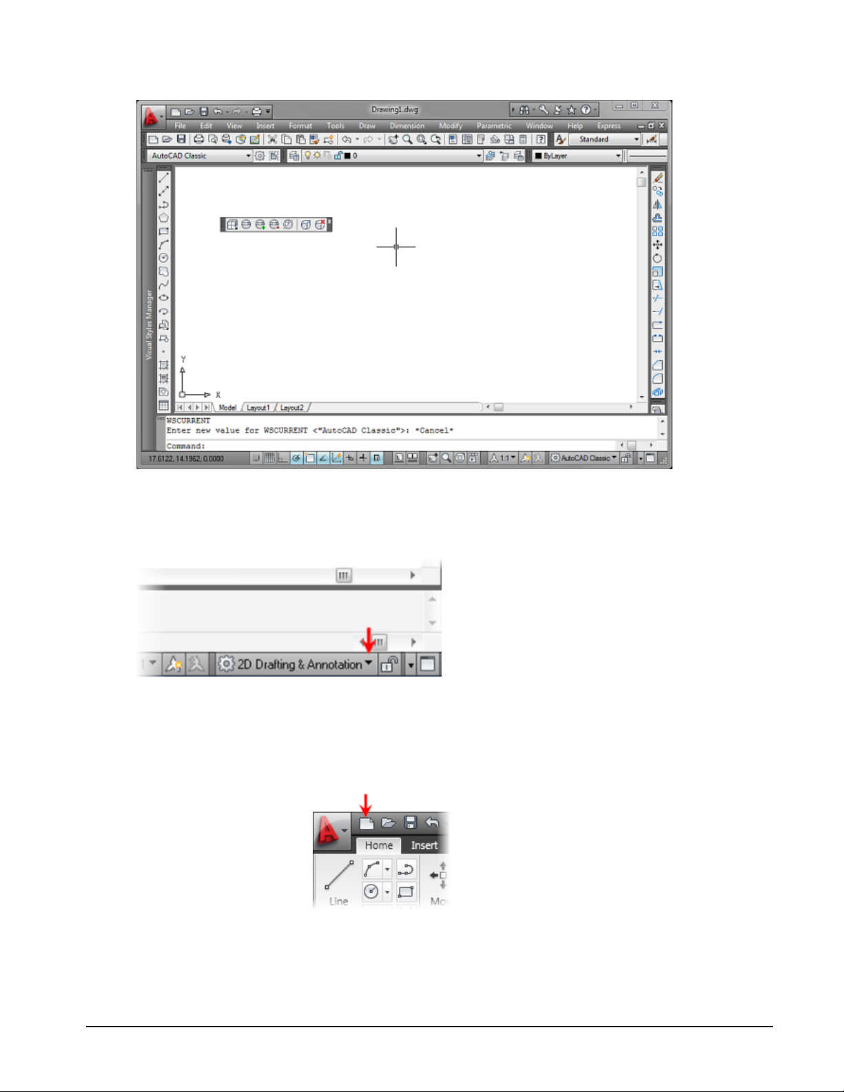
After you start the program you can switch to the desired workspace. The application will open with
the last workspace used. The Workspace Switching dropdown list is accessed in the lower right corner
of the AutoCAD window on the Status Bar.
Procedure: Setting the 2D Drafting & Annotation Workspace
The following steps give an overview of activating the 2D Drafting & Annotation workspace.
1.
Start AutoCAD.
2.
Use the default
drawing or on the
Quick Access toolbar,
click New.
Lesson: Navigating the Working Environment ■ 5
Page 20

3.
Select acad.dwt
(imperial) or
acadiso.dwt (metric)
as the template file.
4.
Click the Workspaces
settings icon, located
at the bottom
right corner of the
AutoCAD window.
Select 2D Drafting &
Annotation.
Procedure: Setting the AutoCAD LT Workspace
The following steps give an overview of activating the AutoCAD LT 2D Drafting & Annotation
workspace.
1.
Launch AutoCAD LT.
2.
On the Workspaces toolbar, select 2D Drafting and Annotation from the list.
3.
Start a new drawing and select acadlt.dwt (imperial) or acadltiso.dwt (metric) as the template file.
The instructions and exercise steps covered in this course are based on the 2D
Drafting & Annotation workspace. Please activate this workspace if you have not
already done so.
6 ■ Chapter 1: Taking the AutoCAD Tour
Page 21

Keyboard Input
Using the keyboard is familiar to everyone who works with computers. For much of the work that you
do in AutoCAD you use the keyboard, but you use a few keystrokes more often than others.
Special Keys
You use the following keys most often. These keys have special meaning to the software.
■ Use the ESC key to cancel all current actions and return to the Command: prompt.
■ Press the ENTER key following all keyboard input. You also complete many commands by pressing
ENTER.
■ Pressing the SPACEBAR is equivalent to pressing the ENTER key and is often easier to use.
■ Pressing the SPACEBAR or ENTER at the Command: prompt repeats the last command used.
■ Pressing the UP and DOWN arrow keys will cycle through previous commands used.
■ The TAB key is especially useful to navigate in a dialog box. You should use the TAB key to move
from field to field. Be careful not to press ENTER.
Function Keys
The use of each of the function keys can be duplicated in other ways with the exception of F2. You may
find that the on-screen equivalents to the function keys are easier and allow you to keep your eyes on
the screen.
Option
Description
F1
F2
F3
F4
F5
F6
F7
F8
F9
Displays Help
Toggles Text Window
Toggles OSNAP
Toggles TABMODE
Toggles ISOPLANE
Toggles UCSDETECT (Not available in AutoCAD LT)
Toggles GRIDMODE
Toggles ORTHOMODE
Toggles SNAPMODE
Lesson: Navigating the Working Environment ■ 7
Page 22

Option
Description
F10
F11
F12
User Interface Layout
There are interface elements common to other Windows applications such as ribbon panels, toolbars,
and menus. If you have used other Windows applications, these user interface elements should
appear familiar. However, there are interface elements such as the command line and the status bar,
which are unique to AutoCAD.
Heads-up Design Defined
Heads-up design is a methodology intended to increase your efficiency while using the software.
Whenever you turn your visual focus away from your design to locate a tool, it slows you down.
Instead, you should use the most efficient access methods such as Dynamic Input, right-click shortcut
menus and the ribbon control panels whenever possible.
Ribbon Defined
The ribbon is a special tool palette associated with each workspace containing only the tools and
controls relevant to that workspace. For example, the ribbon for the 2D Drafting & Annotation
workspace contains tools relevant to 2D drawing, dimensioning, and annotating, but does not contain
tools for 3D geometry creation.
The ribbon supports the heads-up design process because it is space efficient and eliminates the
clutter of tool palettes and toolbars. Using the ribbon alone provides you with more space on your
screen in the drawing area and enables you to maintain access to the tools and controls you need.
Toggles Polar Tracking
Toggles Object Snap Tracking
Toggles Dynamic Input
8 ■ Chapter 1: Taking the AutoCAD Tour
Page 23
Ribbon Controls
The ribbon is turned on by default when you start the software in either the 2D Drafting & Annotation
or the 3D Modeling workspace. The ribbon is organized into a series of tabs. Each tab includes a
different set of panels with related commands and controls that may be found on the Classic AutoCAD
toolbars and dialog boxes.
You can turn the tabs and associated panels on the ribbon on or off by right-clicking on the ribbon area
and selecting Tabs or Panels to select the desired options. You can also turn Panel Titles on or off by
right-clicking the Panel tabs. Additionally you can save your Ribbon configuration.
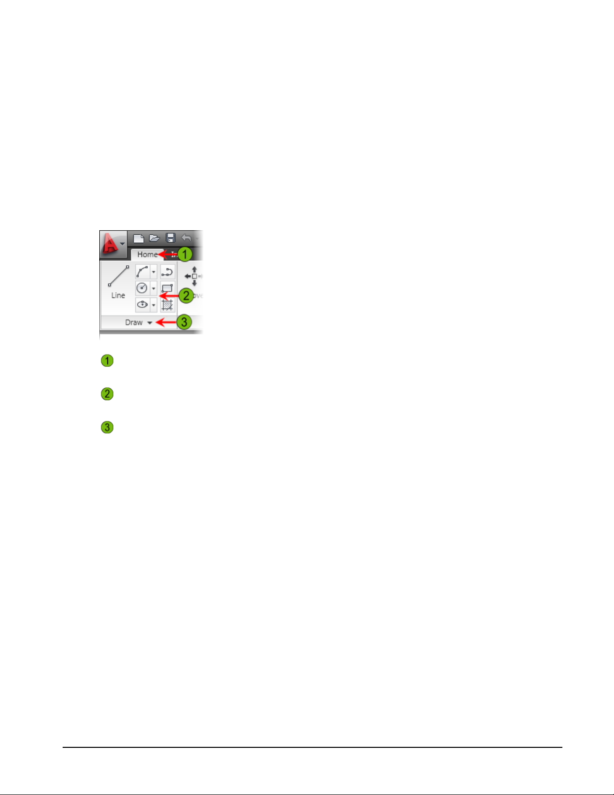
Each tab on the ribbon has its own set of panels that contain groups of related tools, such as those
used for 2D drawing, adding text, or adding dimensions. Some panels can be expanded to display more
tools. Likewise some tools can be expanded for more options, such as the Circle tool as indicated by an
arrow in the corner of the icon.
Tabs
Panels
More tools
Identifies the purpose and name of the control panel.
Contains groups of related tools associated with the selected tools.
Click and hold the down arrow to display more tools and options in the selected
panel.
Lesson: Navigating the Working Environment ■ 9
Page 24
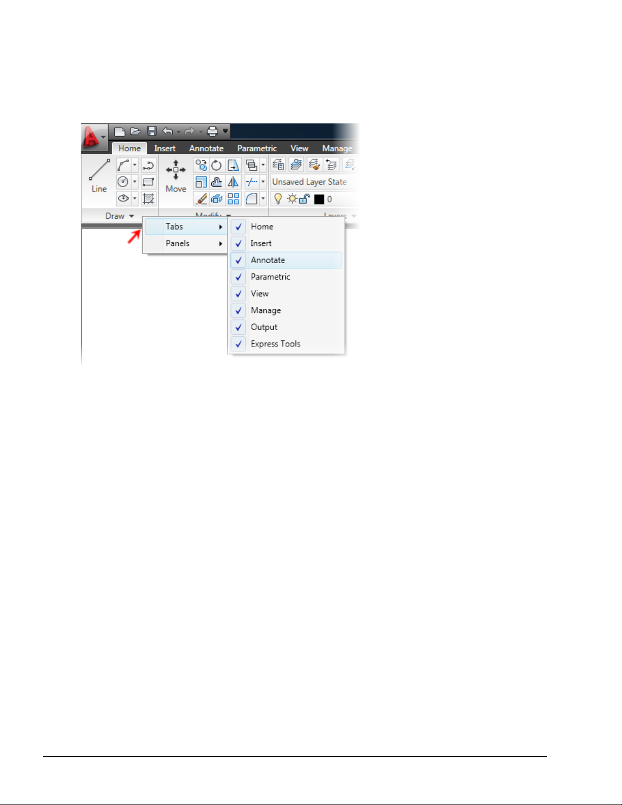
Add or Remove Tabs
To turn specific tabs on or off, right-click in the ribbon and select Tabs. Choose to display or remove
tabs from the ribbon. Tabs currently displayed are indicated with a check mark.
10 ■ Chapter 1: Taking the AutoCAD Tour
Page 25

Application Menu
You can use the Application Menu to accessseveral key commands such as New, Open, Save, Print, and
Close. Most of these commands lead to submenus that give you more detailed options.
Panels
AutoCAD uses ribbon panels as one means to access commands and settings. Similar tools commands
are grouped together in panels and can be accessed by clicking the button or icon that indicates the
tool's purpose. Each panel consists of a collection of tools that performs related or similar tasks.
When using the 2D Drafting & Annotation workspace, a standard set of panels is displayed on each
of the standard set of tabs located on the horizontal ribbon at the top of the AutoCAD drawing area.
Notice that when you select a different tab, a different set of panels is displayed.
By default, each panel is docked at the top of the drawing area on the ribbon. You can move the panels
away from the docked position to a floating position or drag them back into the ribbon.
Lesson: Navigating the Working Environment ■ 11
Page 26

Panel Visibility
To turn specific panels on or off, right-click in the ribbon and select Panels. Select to display or remove
panels from the ribbon tab. Panels currently displayed are indicated with a check mark, as shown in
the illustration on the right.
Panels will appear in the last position (docked or floating) they were in before the panel was removed
from the display.
When you click icons on the ribbon panel, the command is not executed unless the
cursor is over the icon when you release the mouse button. If you click the wrong icon,
simply drag the cursor away from the button before releasing.
Panel Tools Visibility
Some panels will cascade to reveal
additional tools when you select
the black arrow in the lower righthand corner of the panel. You can
keep these panels open to display
all of the tools by selecting the
thumbtack located in the lower
left-hand corner of the cascading
panel.
12 ■ Chapter 1: Taking the AutoCAD Tour
Page 27

Status Bar
The status bar is located at the bottom of the application window.
The left end of the status bar displays the coordinates that show the numerical position of the
crosshairs in the drawing. Click this area to turn the coordinate display off or on. In the on position,
there are two possibilities. The readout displays the X,Y,Z values, or the distance and polar angle of the
crosshairs as it is moved in the drawing window.
Coordinates Display
To the right of the Coordinates Display, there are buttons that activate features to facilitate drawing
construction. Collectively, these features are termed drafting settings.
Drafting Settings
In the middle-right of the status bar are buttons to display the drawing model or the drawing layout
views.
Model Space and Layout Settings
To the right of the Model Space and Layout buttons are the realtime Pan command and the Zoom
command.
Pan and Zoom
Towards the right side of the status bar are the Annotation options for the display of annotative
objects such as text and dimensions. When you create annotations with the annotative property
selected, the Annotation Scale displayed in the status bar represents the scale in which the new
objects are created.
Annotation Settings
Lesson: Navigating the Working Environment ■ 13
Page 28

About Shortcut Menus
The shortcut menu is context-sensitive. When you right-click in the graphics window, you can use the
options presented on the shortcut menu to perform a variety of tasks. Context-sensitive means that
the menu will change depending on what you are currently doing in the software. For example, if you
are at the Command prompt your shortcut menu will have different options available than if you are
in the Pline command.
Definition of Shortcut Menu
Shortcut menu options are organized into different areas. The options that are made available to you
are based on the current context of your work and will change when you activate the shortcut menu.
The following image shows the shortcut menu as it appears when you are creating a polyline.
The top area of the menu offers
Enter, Cancel, and Recent Input
options.
The middle area of the menu offers
options specific to the current
command. Notice how the options
on the menu match the options
on the command line. To use an
option for a command, select the
option on the shortcut menu. This
has the same effect as typing the
capital letter(s) of the option on
the command line.
The lower area of the menu offers
Pan and Zoom functions and access
to the QuickCalc command.
Key Points
■ The shortcut menu is context-sensitive, so its options differ depending on the current context of
the software, for example, whether you are drawing or editing.
■ You can use the shortcut menu as an alternative to entering command options on the command
line. This speeds up the design process and is the preferred method for working with sub-options
of the active command.
14 ■ Chapter 1: Taking the AutoCAD Tour
Page 29

More AutoCAD-Specific Interface Tools
While the software complies with Windows standards for user interface elements, there are some
element types that are specific to the application.
The following image shows the command window. Somewhat unique to a graphical windows
application, the command window provides another method for the user to interact with the
application.
Layouts (Drawing Sheets)
Model space (the Model tab) is the area where you create your designs. Layouts (drawing sheets) are
for annotation, borders, title blocks, and plotting.
When you design, you should always draw at full scale. The model space environment offers an
unlimited amount of space to create your designs. Use layouts to create drawing sheets that represent
an area equal to the actual size of the paper.
You can switch between Model space and the Layout by selecting the button located in the Status Bar
at the bottom of the AutoCAD window.
Lesson: Navigating the Working Environment ■ 15
Page 30

Layer List
The Layer list displays the drawing's layers. Using this list, you can switch the current layer, assign
selected objects to a layer, turn layers on and off, freeze layers, and lock layers.
Tool Palettes
Tool palettes simplify the task of adding predefined design content to your drawing.
16 ■ Chapter 1: Taking the AutoCAD Tour
Page 31

The tool palettes are a set of
overlapping panels contained
in a floating window. For easy
identification, they are grouped by
tabs.
The palettes provide an efficient
method for organizing, sharing,
and placing area fill patterns and
symbols that you use regularly.
You can customize the individual
tools on the palettes by setting
properties that are specific to
the object, such as scale, rotation
angle, or a predefined color.
Palettes can also contain custom
tools provided by third party
developers.
InfoCenter Defined
The InfoCenter, located to the far right of AutoCAD title bar, consists of the InfoCenter search and
access to the Communication Center panel. You can use the InfoCenter search by typing in key words
or by typing a question. While there are many locations for which InfoCenter can be configured, the
following locations are provided as examples:
■ User's Guide
■ Command Reference
■ New Features Workshop
The InfoCenter is shown in the following illustration.
Lesson: Navigating the Working Environment ■ 17
Page 32

Communication Center
The Communications Center, accessed through the InfoCenter menu bar, provides real-time
notifications, announcements, and news to your desktop. You must be connected to the Internet to
take advantage of this feature. The following is a partial list of information sources you can access:
■ New Software Updates
■ Product Support
■ CAD Manager Channel
■ RSS Feeds
Access
Search for information or help in the configured search locations by entering search keywords, or enter
a question in the Help field.
Click the search icon to display the search results after entering search keywords. You can browse the
results in the Search window.
Click the drop-down list to configure InfoCenter. Click Search Settings in the drop-down list to configure
InfoCenter search locations and Communication Center settings.
Click the key to open Subscription Center.
Click the satellite dish icon to open Communication Center.
Click to access a list of favorites.
Click to access the Help dialog box.
Communication Center Options
Expand the Communications Center title bar to see all of
the configured Autodesk channels.
18 ■ Chapter 1: Taking the AutoCAD Tour
Page 33

Expand the RSS Feeds title bar to see all of the configured
RSS feeds. By default, several RSS feeds are created for
you when you install AutoCAD.
Select the Subscription Center button to view all of the
configured Subscription Center items, such as product
support requests and e-Learning catalogs and lessons
(Available to subscription customers only.).
Command Window
The command window is normally located at the bottom of the application window and docked
between the drawing area and status bar. Whether you enter a command manually at the command
line or click a command tool on a toolbar, all commands are passed through and evaluated by the
command line.
It is important that you monitor the activity that occurs in this area. At each stage of the command
process, the software either provides you with a series of options to choose from or requires that you
input values relevant to that stage of the process.
In normal operation, the command window contains three lines of text. The first two lines list
the immediate command history and display the settings or options available within the current
command. The bottom line is the command line. You should focus your attention here during the
majority of commands.
Lesson: Navigating the Working Environment ■ 19
Page 34

You type at the cursor position on the command line, that is, the Command: prompt.
Note: Always press ENTER after you type values on the command line.
Although the command window is usually docked at the bottom of the drawing window, you can move
it freely around the drawing. You can dock it to the edge of the application window or leave it floating
over the drawing area. Click and drag the vertical bars to the left of the command window to place it in
a floating position over the drawing area.
While floating the command window over the drawing area can partially obstruct your
view, you may benefit from this configuration because it serves as a reminder to monitor
the command window.
Command Sequence
The process of entering command sequences is straightforward but important. To use the software
successfully, you must become comfortable with typical command sequences such as the following
one for drawing a circle.
■ Circle
■ Specify center point for circle or [3P/2P/Ttr (tan tan radius)]: Select a point or enter a coordinate.
■ Specify radius of circle or [Diameter] <25.0000>: d (Use a command option.)
■ Specify diameter of circle <50.0000>: 75 (Enter values when prompted.)
If you spend enough time working with the software and paying attention to the command line and
other interface elements, you will soon know what information is required without even looking at
the command line.
20 ■ Chapter 1: Taking the AutoCAD Tour
Page 35

Help Menu
Before you explore the software any further, you should familiarize yourself with the extensive Help
documentation provided.
The Help menu provides access to the Help system as well as online resources for Knowledge Base,
Training Resources, and the Autodesk User Group International (AUGI). You can also find out more
information about and volunteer to participate in the Customer Involvement Program.
Lesson: Navigating the Working Environment ■ 21
Page 36

Lesson: Working with Files
This lesson describes how to open, create, and save drawings.
Objectives
After completing this lesson, you will be able to:
■ Open drawings, create drawings, and save drawings.
Working with Files
Drawings are created and saved in the DWG drawing file format. To access this data, you must learn
how to create a new drawing, save a drawing, and open these file types.
Use the Quick Access toolbar to create, open, and save new drawings.
Open a Drawing
To open a drawing, use the Open command and select the files that you want to open.
Command Access
Open
Command Line: OPEN
Application Menu: File > Open
Toolbar: Quick Access
22 ■ Chapter 1: Taking the AutoCAD Tour
Page 37

Open File Dialog Box
Use standard Windows CTRL+ and SHIFT+ selection methods to select and open
multiple files at once.
Create a New Drawing
To create a new drawing, use the New command. Select a template or select Open with no Template
(Imperial or Metric). Drawing Templates are drawings that are saved in template format (.dwt) and
that can contain information such as a title block, layers, text styles, dimension styles, and settings
relevant to your specific drawing needs.
Command Access
New
Command Line: NEW
Application Menu: File > New
Toolbar: Quick Access
Lesson: Working with Files ■ 23
Page 38

Select Template Dialog Box
Saving Your Drawings
Use the Save command to save your drawing. The first time you save a drawing, the Save Drawing As
dialog box appears. Navigate to the folder where you want to store the drawing, enter a file name,
and select Save. To save a drawing with a different name, select Save As.
Command Access
Save; Save As
Command Line: SAVE; SAVEAS
Application Menu: File > Save; Save As
Toolbar: Quick Access
24 ■ Chapter 1: Taking the AutoCAD Tour
Page 39

Save Drawing As Dialog Box
Save First and Save Often
As a new user, you should get in the habit of saving your drawing as soon as you
create it and save often as you work on your drawings. This is a habit that can be
easily learned and could prove to be very valuable in the event of unexpected system
failures. A quick way to save your work is to use the shortcut keys: Ctrl + S.
Lesson: Working with Files ■ 25
Page 40

Lesson: Displaying Objects
When you use the software, you draw all objects at full scale. Sometimes you need to view the whole
drawing, sometimes just smaller details. To assist you in viewing different areas of the drawing, there
are a number of zoom and pan tools. You can easily magnify small areas of your drawing to provide a
closer view or shift the view to a different or larger part of the drawing. You can save views by name
and restore them later.
In this lesson, you explore different methods of using these tools and develop your use of the
interface.
Many of the zoom and pan options operate transparently. This means that you can use the options
while you are in another command.
After completing this lesson, you will be able to use zoom and pan commands to control the drawing
view display, use the wheel mouse to pan and zoom in the drawing, and regenerate the drawing view.
In the following example of a typical drawing, it would be nearly impossible to work on if it were on
a sheet of paper that was the size of common computer monitors. Using the display tools, you can
magnify any portion of the drawing to fill the available space on your monitor.
Objectives
After completing this lesson, you will be able to:
■ Identify tools that control the drawing view display.
■ Use the Pan Realtime command to perform real time pan operations in the drawing.
■ Use the Zoom Realtime command to perform real time zoom operations in the drawing.
■ Use different Zoom commands to control the view magnification.
■ Use a wheel mouse to zoom and pan in the drawing.
■ Use the Regen command to regenerate the drawing.
26 ■ Chapter 1: Taking the AutoCAD Tour
Page 41

Display Tools
Most of the time you will use the wheel on your mouse to zoom in and out of display views in your
drawing. Additional zoom tools are located on the Navigate panel in the View tab on the toolbar
ribbon.
Command Access
Display Tools
Command Line: Zoom, Z or Pan
Status Bar: Pan or Zoom
Ribbon: View tab > Navigate panel > Pan
There are additional options for the Zoom command, but they are beyond the scope
of this course. See Help for additional command information.
Pan
You can reposition the center of your view on the drawing by using the Pan command. Just like
panning with a video camera, panning your drawing changes only the position of your view of the
drawing, not the location or magnification of objects in the drawing.
Lesson: Displaying Objects ■ 27
Page 42

Command Access
Pan
Command Line: PAN, P
Ribbon: View tab > Navigate panel > Pan
Shortcut Menu: Pan
When the Pan command is active, the cursor changes to a hand icon as shown above. Click and drag
the cursor to pan the drawing view.
28 ■ Chapter 1: Taking the AutoCAD Tour
Page 43

Command Options
While in the Pan command you may access other Pan and Zoom options when you right-click in the
drawing window to display a shortcut menu.
Option
Description
The 3D Orbit option is not available in AutoCAD LT.
Warning!
Exit: Select to exit the Pan or Zoom Realtime commands.
Zoom: Select to switch to Zoom Realtime.
3D Orbit: Select to perform a 3D Orbit of the view.
Zoom Window: Select to perform a Zoom Window operation and return
to the Pan or Zoom Realtime command.
Zoom Original: Select to return to the view prior to starting the Pan or
Zoom Realtime command.
Zoom Extents: Select to zoom to the drawing extents and return to the
Pan or Zoom Realtime command.
Procedure: Panning in Real Time
The following steps outline how to pan dynamically in real time.
1.
On the ribbon, click View tab > Navigate panel > Pan.
2.
Click and drag the cursor in the direction that you want to pan the drawing view. Release the button
when you are in your desired position.
Lesson: Displaying Objects ■ 29
Page 44

3.
Continue to click and drag as required.
4.
Press ESC or ENTER to exit the Pan command.
Panning Considerations
■ Panning has the same effect on the drawing as using the horizontal and vertical scroll bars.
■ When you pan the drawing, you are not moving geometry, only changing the position from which
you view the drawing.
Zoom Realtime
The Zoom command increases or decreases the magnification of the objects displayed in the drawing
area. When you zoom out, you see more of the overall drawing. When you zoom in, you magnify parts
of your drawing to view them in greater detail.
Just like zooming in and out with a camera, using Zoom does not alter the actual size of the object. It
simply changes the relative magnification of objects displayed in the drawing area.
Command Access
Zoom
Command Line: Zoom, Z Press ENTER on the keyboard for Realtime option
Status Bar: Zoom
Ribbon: View Tab > Navigate Panel > Zoom drop-down > Realtime
30 ■ Chapter 1: Taking the AutoCAD Tour
Page 45

Zoom
Note: If the Zoom realtime icon is not readily available, select it from the drop down list.
When the Zoom Realtime command is active, the cursor changes to the icon above. Click and drag the
cursor up to increase magnification or down to decrease magnification.
Shortcut Menu: Zoom
Procedure: Zooming in Real Time
The following steps outline how to zoom dynamically in real time.
1.
On the ribbon, click View Tab > Navigate Panel > Zoom drop-down > Realtime. Press ENTER.
2.
Click and drag the cursor up to increase magnification.
Lesson: Displaying Objects ■ 31
Page 46

3.
Click and drag the cursor down to decrease magnification.
4.
Continue to zoom in and out as required.
5.
Press ESC or ENTER to exit the command.
Zoom Command Options
The Zoom command has multiple options availabe to customize the Zoom.
Command Access
Following are the most frequently used Zoom command options for viewing different areas of the
drawing.
Note: Not all Zoom command options are discussed.
Zoom Command Options
Command Line: Zoom, Z (see the Command Line option for the Zoom commands listed
below)
Ribbon: View tab > Navigate panel > Zoom pull-down
32 ■ Chapter 1: Taking the AutoCAD Tour
Page 47

Zoom Command Options
Zoom Window
Zoom Extents
Zoom Previous
ZOOM, Z; Pick 2 points to define the window in the drawing area
To use the Zoom Window option, use any method listed above to start the command, click
in the drawing to specify the first corner of the window (1), and then click to specify the
second corner of the window (2). As a result, the drawing view is magnified and fills the
drawing space with the area defined by the zoom window.
Use the Zoom Extents option to zoom to the extents of the drawing, that is, the area of the
drawing in which objects are placed. When you zoom to the drawing extents, you magnify
the drawing view so that all geometry in the current space (model space or paper space) is
visible.
ZOOM, Z; > E then press ENTER
Use the Zoom Previous option to return to the previous view.
ZOOM, Z; > P then press ENTER
Lesson: Displaying Objects ■ 33
Page 48

Wheel Mouse Features
The wheel mouse is a variant of the standard pointing device that is modified with a small wheel
between the left and right buttons. You can rotate this wheel in small increments. You can use the
wheel to zoom and pan in your drawing without using any commands. When zooming in, the location
near your cursor is the focal point of the zoom and thus remains on the screen.
The ZOOMFACTOR system variable controls the incremental change, whether forward or backward.
The higher the number of the variable, the greater the zoom.
How to Use the Wheel Mouse
Do this...
To...
Roll the wheel forward
Roll the wheel backward
Double-click the wheel button
Hold down the wheel button and drag the mouse
Press and hold the SHIFT key and the wheel button and drag
the mouse
Press and hold the CTRL key and the wheel button and drag
the mouse
In some situations, when using the mouse wheel to pan or zoom, the actions have no
effect on the drawing. For example, you might only be able to zoom out to a certain
point. When this occurs, you must regenerate the drawing by clicking Regen on the View
menu.
Zoom In
Zoom Out
Zoom Extents
Pan
Constrained Orbit
Pan (Joystick)
Wheel Button Modes
You can set the wheel button to function in two different modes. The value of the MBUTTONPAN
system variable controls whether panning is supported.
■ If MBUTTONPAN is set to 1, the PAN command is activated when you use the wheel.
■ If MBUTTONPAN is set to 0, the Object Snap menu is displayed when you use the wheel.
34 ■ Chapter 1: Taking the AutoCAD Tour
Page 49

Regen
Use the Regen command to regenerate all the geometry in the drawing.Use theRegenall command
to regenerate all the geometry when there are multiple drawing viewports.When you regenerate
the drawing, the screen coordinates for all objects in the drawing are recomputed and the drawing
database is reindexed for optimal display performance.
Command Access
Regen
Command Line: RE, REGEN, REGENALL
Automatic Drawing Regeneration
By default, when you create a new drawing, the REGENMODE system variable is set
to 1. Thisenables the drawing to regenerate automatically whenever you perform an
action that requires regeneration.
Guidelines When Regenerating Large Drawings
■ Because regeneration recalculates the screen coordinates for all objects in the drawing, it usually
takes longer to regenerate large drawings than smaller ones.
■ If you experience performance decreases on larger drawings, consider setting REGENMODE = 0 to
prevent automatic regeneration. You can manually regenerate the drawing when you need to.
Lesson: Displaying Objects ■ 35
Page 50

Exercise: Zoom and Pan in the Drawing
In this exercise, you open an existing drawing and use the Zoom and Pan tools to view different areas.
The completed exercise
Completing the Exercise
To complete the exercise, follow
the steps in this book or in the
onscreen exercise. In the onscreen
list of chapters and exercises, click
Chapter 1: Taking the AutoCAD Tour.
Click Exercise: Zoom and Pan in the
Drawing.
5.
Right-click anywhere in the drawing. Click Exit
to end the Pan command.
Note: You can also press ESC to end the
command.
6.
On the status bar, click Zoom. Enter E in the
command line to select the Extents option.
Notice how the view changes.
Note: If you have a three-button mouse with
a scroll wheel, you can double-click the wheel
button for the Zoom Extents command.
1.
Open C_Displaying-Objects.dwg.
2.
On the View Tab, click Navigate Panel > Pan.
3.
Alternatively:
■ Right-click anywhere in the drawing area.
Click Pan.
■ Click and hold the mouse button and drag
4.
to change your view of the drawing.
While still panning the drawing, press and hold
SHIFT.
Note: This temporarily restricts the movement
of the pan from any direction to orthogonal
mode.
36 ■ Chapter 1: Taking the AutoCAD Tour
Page 51

7.
Zoom in real time:
■ On the status bar, click Zoom.
■ Press ENTER to select real time.
■ Click and hold your mouse button and
move the cursor up.
■ Still holding the mouse button, move the
cursor down.
■ Notice that as you move the cursor up, the
drawing zooms in and as you move the
cursor down, it zooms out.
Note: You can also activate the Zoom Realtime
command by rotating the wheel on a wheel
mouse. Rotating the wheel away from you
zooms in, and rotating toward you zooms out.
8.
Zoom to a window:
■ On the View tab, click Navigate panel >
Zoom drop-down > Window.
■ Click two points around the center section
of the drawing as shown by the arrows in
the following illustration.
9.
Pan to the lower left corner of the drawing.
10.
On the View tab, click Navigate panel > Zoom
drop-down > Previous. This returns you to the
last view of the drawing that you zoomed or
panned to.
Note: Only the last 10 view changes are saved.
11.
Close all files. Do not save.
Lesson: Displaying Objects ■ 37
Page 52

Exercise: Hands-On Tour
In this exercise, you open an existing drawing. You use display commands and explore the user interface.
The completed exercise
2.
Completing the Exercise
To complete the exercise, follow the
steps in this book or in the onscreen
exercise. In the onscreen list of
chapters and exercises, click Chapter
1: Taking the AutoCAD Tour. Click
Exercise: Hands-On Tour.
On the status bar, click Zoom. Enter E and
press ENTER to select the Zoom Extents
option. The drawing is magnified to fill the
screen. If your workstation is equipped with a
wheel mouse, double-clicking the roller button
also selects Zoom Extents.
1.
Open C_Hummer-Elevation.dwg.
Because the drawing was last saved with the
Color layout view active, the drawing opens to
that layout.
3.
Use the wheel mouse, if you have it. Position
the cursor to the left of the top view and roll
the wheel forward then backward. If you do
not have a wheel mouse, right-click anywhere
in the drawing window and click Zoom. Hold
the left button down and drag the mouse up
and down. See how the magnification changes.
38 ■ Chapter 1: Taking the AutoCAD Tour
Page 53

4.
On the View tab, click Navigate panel > Zoom
drop-down > Extents to view the entire
drawing layout.
5.
Now you switch the drawing view to model
space, which is where the geometry for the
drawing resides. On the status bar, at the
bottom of the AutoCAD window and to the
right, click Model.
7.
On the View tab, click Navigate panel > Zoom
drop-down list > Previous. This returns you to
the previous view.
8.
On the Quick Access toolbar, click Save.
9.
In the Application Menu, select File > Close.
6.
On the View tab, click Navigate panel > Zoom
drop-down list > Window. Click near the
points indicated in the following illustration to
magnify the area defined by the window.
10.
In the Application Menu, top right, you see a
list of previously opened files for quick access.
Exercise: Hands-On Tour ■ 39
Page 54

Select the C_Hummer-Elevation drawing.
Notice that it is opened to the last view in
which it was saved.
11.
On the bottom right of the AutoCAD window,
click Layout to activate the color layout. Close
the drawing.
12.
Now you start a new drawing. On the Quick
Access toolbar, click New.
13.
In the Select Template dialog box, click the
arrow next to Open. Click Open with no
Template - Imperial. This opens a blank
drawing with basic settings that you can
change, such as the units format.
Note: For AutoCAD LT users, click acadlt.dwt.
14.
Move your cursor near the upper right corner
of your drawing area. Observe that the
coordinate readout shows a screen size of
about 12 x 9 units.
15.
Close all files. Do not save.
40 ■ Chapter 1: Taking the AutoCAD Tour
Page 55

Chapter Summary
Now that you have been introduced to several core features, you can begin learning how to create
geometry.
Having completed this chapter, you can:
■ Identify and state the purpose of the main interface elements.
■ Open, create, and save drawings.
■ Use the Zoom and Pan commands to view different areas of the drawing.
Chapter Summary ■ 41
Page 56

42 ■ Chapter 1: Taking the AutoCAD Tour
Page 57

Chapter
2
Creating Basic Drawings
Every drawing begins with the creation of basic geometry, objects such as lines, circles, arcs, and
rectangles. These objects serve as building blocks for complex drawings and, as a result, you must
master the use of the commands that create these objects.
Mastering these commands involves more than just knowing where the command is and how it works.
You must also develop an understanding of the underlying coordinate system, and the settings such as
object snaps, object snap tracking, and other features that are designed to assist you in creating basic
objects.
There is generally more than one way to accomplish a task in the software. After you learn about the
commands and features available, you can determine the methods that work best for you.
This chapter, and all subsequent chapters of the book, assume that you will be using the 2D Drafting &
Annotations workspace with the toolbar ribbon at the top of the AutoCAD® window. If you are using
AutoCAD LT®, while you might see slight interface differences, every attempt has been made to retain
the fidelity of the learning experience when using this book.
Objectives
After completing this chapter, you will be able to:
■ Identify the default coordinate system and use dynamic input, direct distance, and shortcut menus.
■ Use the Line, Circle, Arc, Erase, Rectangle, and Polygon commands to create and erase geometry in
the drawing.
■ Use object snaps to accurately place and create objects in the drawing.
■ Activate and use the Polar Tracking and PolarSnap modes to more accurately create geometry at
different angles in the drawing.
■ Explain, enable, and use object snap tracking to position geometry in the drawing.
■ Use the Unit command to set up the drawing environment.
■ Use the concepts and tools that you learned in Chapter 2 to begin a small architectural floor plan.
■ Use the concepts and tools that you learned in Chapter 2 to create the initial geometry for a small
mechanical assembly drawing.
Chapter Overview ■ 43
Page 58

Standard Object Snap and Status Bar Settings
Before completing the exercises in this chapter, refer to the "Settings for the
Exercises" section in the Introduction in Volume 1.
44 ■ Chapter 2: Creating Basic Drawings
Page 59

Lesson: Inputting Data
Every drawing action requires some form of data input. Regardless of the types of geometry you
create, you are constantly inputting data in one form or another.
In this lesson, you will learn to input data using the command line, dynamic input, direct distance
entry, shortcut menus, and the Cartesian coordinate system. You will use the concepts you learn in this
lesson in exercises throughout this course.
After completing this lesson, you will be able to use the command line, explain different types of
coordinates, activate and use the Dynamic Input interface, use direct distance to enter values, and use
the shortcut menu to access commands and options.
The following image illustrates how to use the Dynamic Input interface to draw a 10 unit line at 30
degrees.
Objectives
After completing this lesson, you will be able to:
■ Use the command line to enter commands and command options.
■ Explain the difference between a Cartesian and a polar coordinate, and between an absolute and a
relative coordinate.
■ Activate the dynamic input interface and list key points about using it.
■ Create and edit geometry using the dynamic input interface.
■ Use direct distance entry to enter distance values.
Lesson: Inputting Data ■ 45
Page 60

About the Command Line
There are specific AutoCAD elements such as the ribbon, menus, and other tools that are common to
all Microsoft Windows applications. However, the command line interface is unique to AutoCAD.
Most commands have options with which you can control various aspects of how the command is
used. You should pay attention to the command line as you work.
Command Line Defined
The command line is the primary place where you communicate with the software. On the command
line, you are prompted to input information.
Command Line Options
■ Command options appear on the command line. The capitalized letter(s) represents the letter(s)
you enter to use that option. You are not required to enter the letter(s) as a capital letter.
■ Options for the command appear within [...] brackets. If there is a default option for the
command, it appears within <...> brackets. To use the default option, press ENTER.
■ Press the F2 key to display the full command window. Each command that you use during your
drawing session is saved here. Press F2 again to close the full command window.
The following image shows command line options and a command line default value. In this situation,
the user has started the rectangle command, and has entered d for the Dimension option. After
pressing ENTER, a default distance of 7.0000 is displayed. If the user does nothing but press ENTER, a
value of 7.0000 is used.
Command Line Example
The following image shows a typical command and its options as they are presented on the command
line. The last line shows the current status of the command. The previous lines show the command
line history.
46 ■ Chapter 2: Creating Basic Drawings
Page 61

About the Coordinate System
Every object you draw is placed in either the world coordinate system (WCS) or a user coordinate
system (UCS). When you create 2D geometry, data input is ultimately passed to the software in the
form of Cartesian (x,y) or polar coordinates (distance, angle). You can either manually enter these
coordinates or infer them by picking a point in the drawing window.
Cartesian Coordinate System
Every object you draw is placed in either the World Coordinate System (WCS) or a User Coordinate
System (UCS). When you create 2D geometry, data input is ultimately passed to the software in the
form of Cartesian (x,y) or polar coordinates (distance, angle). You can either manually enter these
coordinates or infer them by picking a point in the drawing window.
The Cartesian coordinate system is used to determine points in space that are a specified distance
from a set of perpendicular axes that intersect at the origin of the system.
In the World coordinate system, the X axis represents the horizontal direction, the Y axis represents
the vertical direction and the origin is located at 0,0. Positive X moves to the right, positive Y moves up,
and the Z axis moves in the positive direction directly towards you, the viewer.
Note that for this course we will only be concerned with the X & Y coordinates since we are working in
2D. The Z coordinate will always be zero and need not be specified.
The following image illustrates a line drawn from the origin of the coordinate system 0,0 with its
endpoint at the coordinate 4,6.
To specify a Cartesian coordinate, type the X and Y coordinates and press ENTER. Example: 4,5 where
X is equal to the distance from the origin along the X axis and Y is equal to the distance from the origin
along the Y axis.
Lesson: Inputting Data ■ 47
Page 62

Polar Coordinates
A polar coordinate is a point in the coordinate system that is determined by a distance and an angle.
The following illustration shows a line drawn from the origin of the coordinate system with a length of
7 units and an angle of 45 degrees.
To specify a polar coordinate, type the distance < angle, example 5<45, where Distance equals the
distance traveled from the specified origin point and Angle equals the angle from the X axis.
Polar Angle
The default polar angle is measured counterclockwise from the zero angle position. The default zero
angle is in the East compass direction.
The following illustration shows how angles are defined with a polar coordinate. This angle
measurement applies to entering coordinates, working with arcs, and rotating objects.
48 ■ Chapter 2: Creating Basic Drawings
Page 63

Absolute and Relative Coordinates
When you type coordinates, they can be in the form of an absolute or a relative coordinate.
■ An absolute coordinate represents a specific point in the current coordinate system relative to the
origin point (0,0). To enter an absolute coordinate, type the values as a Cartesian coordinate (x,y)
or Polar coordinate (distance angle).
■ A relative coordinate is a point located from a previously selected point. To enter a relative
coordinate, select your first point, then precede the next coordinate point with the @ symbol. For
example @5<45 would mean 5 units at 45 degrees from the last point selected, and @3,5 would
mean 3 units in the positive x direction and 5 units in the positive y direction from the last point
selected.
Note that when the Dynamic Input option is selected in the Status Bar relativity is automatically
assumed.
Entering Coordinates
■ You can enter coordinates any time the software is in point acquisition mode, that is, when the
Command line is prompting you to specify a point or distance.
■ Every drawing contains the world coordinate system (WCS). The WCS is identical in every drawing
and cannot be altered. For example, an object placed at the absolute coordinate 10,10 would be
positioned in the same location in any drawing.
■ Unless you specifically define a User Coordinate System, all geometry you create is drawn relative
to the WCS.
The UCS icon displays differently when you are working in the world coordinate system
versus a user coordinate system. The UCS icon for the world coordinate system contains
a small box at the origin of the X and Y axes.
Absolute and Relative Coordinate Examples
Coordinate
Cartesian coordinate
Polar coordinate
Absolute
24,46
15<45
Relative
@24,46
@15<45
Lesson: Inputting Data ■ 49
Page 64

Example of Cartesian Coordinate Input
The following lines could have been drawn using Cartesian or Polar coordinates. Assuming the start
point at the red arrow, the command line input for relative Cartesian or Polar coordinates would be as
follows:
Point 2: @4,0 or @4<0
Point 3: @0,2 or @2<90
Point 4: @-1,0 or @1<180
About Dynamic Input
The Dynamic Input interface is a way of entering data dynamically. Rather than entering data on the
command line, which is generally positioned at the bottom of the screen, you can use the Dynamic
Input interface for heads-up design, entering command information on screen at the cursor location.
Using the Dynamic Input Interface
The Dynamic Input interface is context sensitive based on the current operation. For example, the
input and options are different when you are drawing a line than when you are drawing a circle; they
also differ based on whether you are creating or editing geometry.
Dynamic Input Interface: Dimensional Input Mode
There are two Dynamic Input interface modes: Dimensional Input and Pointer Input. The following
image represents the Dynamic Input interface in Dimensional Input mode. This mode is available
when the Dynamic Input option is selected in the status bar and is commonly used for the typical
drawing commands such as Line, Circle, and Arc.
Note: Numbers in the following image correspond to the numbers in the list below.
50 ■ Chapter 2: Creating Basic Drawings
Page 65

1. Tooltip: Displays instructions for the current step in the command and also reflects the current
prompt on the command line.
2. Coordinate, Length, or Angle input fields: Depending on the mode, these fields may vary in value
and position. In the image, one field represents the current length of the polyline while the other
represents the angle of the cursor. Enter a value to specify an explicit value. Press TAB to cycle
between the fields.
3. Down Arrow: Press DOWN ARROW (on the keyboard) to display the Dynamic Input menu. Press UP
ARROW to cycle through previously selected coordinates.
4. Dynamic Input Menu: Select an option for the command. Available options vary based on the
current context and reflect the options available on the command line.
Dynamic Input Interface—Pointer Input Mode
In the following illustration, the Dynamic Input interface has changed to Pointer Input mode because
the values @ 10 < 45 were entered on the keyboard. In Pointer Input mode, you can enter coordinate
information at the pointer as though your focus were on the command line. Use this mode for
absolute and relative coordinates. It is also the default mode for commands such as Move, Copy, and
Rotate.
Lock icons indicate a value that has been manually entered. To unlock a value, press TAB to enter the
input field, press DELETE to clear the value, then press TAB to exit the input field.
The default mode for dynamic input is for relative coordinates, but you can also enter absolute
coordinates. To do so, enter a pound sign before the first coordinate, for example, #2,20. If you enter
2,20 (without the # sign), the point will be relative to the last selected point. The dynamic input fields
adjust to reflect the entry format. In this case, the second field represents the Y coordinate.
Lesson: Inputting Data ■ 51
Page 66

Dynamic Input Options
Use the Dynamic Input tab in the Drafting Settings dialog box to change settings related to the
Dynamic Input interface.
Click to adjust Pointer Input options.
Click to adjust Dimensional Input options.
Click to adjust appearance-related options for the Dynamic Input tooltips.
Guidelines for Using Dynamic Input
■ When you use grips to stretch objects, or when you create new objects, dimensional input
displays only acute angles; that is, all angles are displayed as 180 degrees or less. Thus, an angle of
270 degrees is displayed as 90 degrees. Angles that you specify when creating new objects rely on
the cursor location to determine the positive angle direction.
■ Dynamic Input is not intended to replace the command window. You use both the dynamic
interface prompts and the command line in your workflow.
■ The Dynamic Input interface is context sensitive.
■ When Dynamic Input is on, points that you enter in response to second or next point prompts
default to relative.
■ Depending on the location of the cursor and the status of other settings such as object snaps,
polar tracking, and tooltips, other information may appear on the Dynamic Input interface
including object snap tips and command line prompts.
52 ■ Chapter 2: Creating Basic Drawings
Page 67

Using the Dynamic Input Interface
You can usethe Dynamic Input interface in several ways, buttheprimary goal of the tool is to let you
draw and edit in a heads-up mode, with your focus on the graphics window instead of the command
line. Because the Dynamic Input interface is context sensitive, its options and display modes are
dependent on the context in which you are working. The following guidelines give an overview of how
you can use the Dynamic Input interface during typical drawing and editing tasks.
Command Access
Dynamic Input Mode
Command Line: DYNMODE
Function Key: F12
Procedure: Drawing with Dynamic Input
The following steps give an overview of creating geometry using the Dynamic Input interface and Polar
coordinates. Note that because the Dynamic Input display is activated, relativity is assumed and it is
not necessary to enter the ampersand symbol (@).
Lesson: Inputting Data ■ 53
Page 68

1.
Begin a command. The Dynamic Input field displays the command.
2.
After you press ENTER, the interface immediately switches to Point Input mode. The tooltip gives
instructions for what is required and the input fields reflect the current XY coordinate location of the
cursor.
3.
The Dynamic Input display prompts you for the next point. Enter a value in the Distance input field and
press TAB to lock the distance and activate the Angle input field. Enter a value in the Angle input field
and press TAB to lock the angle at 0 degrees. Click to select the point.
54 ■ Chapter 2: Creating Basic Drawings
Page 69

4.
Enter another value in the Distance input field and press TAB to lock the distance. Move the cursor to
adjust the angle value shown but note that if you simply click, the angle is rounded up to the nearest
whole number as determined in the Units settings. It would be best to enter the angle for accuracy.
5.
Click the final point and press ENTER to complete the line.
6.
Your finished object is shown.
Lesson: Inputting Data ■ 55
Page 70

Procedure: Editing with Dynamic Input
The following steps give an overview of some of the ways you can edit with the Dynamic Input
interface.
1.
On the Home tab, click Modify panel > Copy. Select the objects to be copied and press ENTER to
complete your selection.
2.
The Dynamic Input interface prompts you to Specify a base point. Notice the blue down arrow. Using
the arrow keys on your keyboard, you may switch to single copy mode or multiple copy mode . Select a
base point on or near the object.
3.
The Dynamic Input tooltip provides feedback. Entering @38.500<180 puts the interface in Relative
Coordinate mode and places the values in the correct input fields. Press ENTER to complete the Copy
command.
56 ■ Chapter 2: Creating Basic Drawings
Page 71

4.
Select the circle to activate the grips.
5.
Select a quadrant grip to display the Dynamic Input interface. Grip editing displays several options. You
can resize the circle either by entering a new radius (1), or Tab for one of the other options to increase
or decrease the radius (2). Enter a value in one of the input fields and press ENTER.
The circle is resized.
Lesson: Inputting Data ■ 57
Page 72

Using the Dynamic Input Interface to Reveal Information
You can see the length or angle of a line or the radius of an arc or circle by using the object grips. With
the command line blank, select the geometry to activate the grips. Hover the cursor over one of the
end grips or circle quadrants without selecting the grip. The Dynamic Input interface displays size
information for the selected geometry.
Guidelines for Using Dynamic Input
■ When entering length or angle, press TAB to lock the values.
■ Before entering the length or angle, you may press TAB to cycle through the available input fields.
Enter the desired values and press ENTER to complete the command.
■ To reveal the length or angle of a line, or the radius of an arc or circle, select the geometry (with
the Command line blank) to activate the grips. Hover the crosshairs over one of the grips. The
Dynamic Input interface displays size information for the selected geometry.
■ To Modify an object using Grips, select the object (with the Command line blank) and then select a
grip. Press TAB to cycle through the available fields. Supply the desired data and press ENTER.
■ When Dynamic Input is on, points you enter in response to second or next point prompts default
to relative.
■ To enter X,Y coordinate values, press # to switch to absolute coordinate entry mode.
Using Direct Distance Entry
Direct distance entry is by far the easiest and quickest way to enter data while using the Draw and
Modify commands. You can enter a distance value whenever the software prompts you to select
a point. The point coordinates are calculated based on the angle of the cursor from the previous
point selected and the distance you enter. It is a good idea to have Polar Tracking on when using this
58 ■ Chapter 2: Creating Basic Drawings
method.
You may use this method of data entry whether the Dynamic Input mode is on or off.
Page 73

Guidelines for Using Direct Distance Entry
■ Turn Polar Tracking on to display the cursor's angle.
■ Set the desired incremental polar angles in Polar Tracking settings.
■ Enter the desired distance and press ENTER. Be sure that the accurate Polar angle is displayed.
■ AutoCAD is accurate 14 places to the right of the decimal point (1.00000000000000). Therefore, it
is important to enter the distance and use Polar Snap for absolute precision.
■ Although turning Dynamic Input off limits the data fields displayed by your pointer, you may use
Direct Distance entry with this feature on or off.
Procedure: Using Direct Distance Entry
The following steps give an overview for using the direct distance entry method.
1.
Start a command such as Line and click a point to begin.
Tip: Toggle off Dynamic Input on the status bar for clearer results.
Lesson: Inputting Data ■ 59
Page 74

2.
When you are prompted to specify the next point, drag your cursor in the direction you want the line to
travel, enter a distance on the command line, then press ENTER.
Tip: Turn polar tracking on to display the current angle of your cursor.
3.
Drag the cursor in the direction of the next line segment, enter a distance value, and press ENTER.
4.
Repeat step 2 until the geometry is completed.
60 ■ Chapter 2: Creating Basic Drawings
Page 75

5.
Press ENTER to exit the command.Your object is completed.
Lesson: Inputting Data ■ 61
Page 76

Exercise: Input Data
In this exercise, you gain familiarity with the various input methods including the command line, the
keyboard, and the dynamic interface.
The completed exercise
Completing the Exercise
To complete the exercise, follow the
steps in this book or in the onscreen
exercise. In the onscreen list of
chapters and exercises, click Chapter 2:
Creating Basic Drawings. Click Exercise:
Input Data.
1.
On the Quick Access toolbar, click New.
2.
In the Select Template dialog box, click the
arrow next to Open and select Open with no
Template - Imperial.
Note: For AutoCAD LT users, select acadlt.dwt.
3.
On the status bar, make sure dynamic input is
off.
62 ■ Chapter 2: Creating Basic Drawings
Page 77

4.
Use the Command line to create a circle:
■ Enter Circle. Press ENTER.
■ Observe the options listed in the brackets.
■ Click near the center of the graphics
window for the center point.
■ Enter 1. Press ENTER.
Zoom to view your drawing, if necessary.
5.
To draw a second circle the same size as the
first:
■ Press ENTER. This repeats the previous
command.
■ Click to select a point to the left of the first
circle.
■ Press ENTER to accept the default value for
the circle radius.
■ Enter c for the close option. Press ENTER.
7.
Display the command history:
■ Press F2.
■ Review the command history shown. Use
the scroll function on the right side of the
window or the mouse wheel to display
additional history.
■ Press F2 again to turn off the command
window.
6.
Use the Line command with relative polar
coordinates to draw a triangle near the circles:
■ To begin the Line command, enter L for
line. Press ENTER.
■ Specify a point in the drawing window for
the first point (1).
■ Enter the polar coordinate @2<45 (2).
Press ENTER.
■ Enter the polar coordinate @2<135 (3).
Press ENTER.
8.
Turn on Dynamic Input. On the status bar, click
Dynamic Input.
Lesson: Inputting Data ■ 63
Page 78

9.
Reveal geometric data using the dynamic
interface:
■ Click to select the first circle that you
created.
■ Place your crosshairs over, but do not click
the square grip box on the right edge of
the circle.
■ Verify that the circle radius is 1.
■ Press ESC to remove the circle selection.
10.
Reveal additional geometric data using the
Dynamic Input interface:
■ Click the two angular lines that you
created.
■ Place your crosshairs over, but do not click
the square grip box at the intersection of
the two lines.
■ Observe that both the length and angle
data are displayed for the selected lines.
■ Press ESC to remove the line selection.
11.
Close all files. Do not save.
64 ■ Chapter 2: Creating Basic Drawings
Page 79

Lesson: Creating Basic Objects
All drawings consist of basic objects that you create using basic commands. In this lesson, you learn
how to create objects such as lines, circles, arcs, rectangles, and polygons. You also learn how to use
the Erase command to erase objects.
Learning to create basic geometry is critical to success in the software. As you become proficient with
basic geometry creation, you can move on to creating more advanced object types.
Objectives
After completing this lesson, you will be able to:
■ Use the Line command to create lines in the drawing.
■ Use the Circle command to create circles in the drawing.
■ Use the Arc command to create arcs in the drawing.
■ Use the Erase command to erase objects in the drawing.
■ Use the Undo and Redo commands to return to previous drawing states.
■ Use the Rectangle command to create rectangles in the drawing.
■ Use the Polygon command to create equal-sided polygons in the drawing.
Lesson: Creating Basic Objects ■ 65
Page 80

Line Command
Use the Line command to create a single line or multiple line segments from a start point to an
endpoint.
The following illustration shows a line segment being drawn using the dynamic input interface to
specify the length (1) and angle (2) of the segment.
Command Access
Line
Command Line: Line, L
Ribbon: Home tab > Draw panel > Line
Menu Bar: Draw > Line
66 ■ Chapter 2: Creating Basic Drawings
Page 81

Command Options
The following Line command options are available from the shortcut menu (right-click) or the
Command line:
Option
Description
First point
Next point
(default) Specifies the start point of the line segment.
(default) Specifies the endpoint of the line segment. Continue to specify next points
for additional line segments.
Undo
Removes the previous line segment without exiting the Line command. Select or
enter the capitalized letter only.
Close
Appears only after you have drawn two line segments. Uses the first point of the line
segments as the next point for the current segment to create a closed boundary of
line segments. Select or enter the capitalized letter only.
Line Command Guidelines
■ Use to create a single line or multiple line segments.
■ Use the Close option to connect the last segment to the beginning of the first segment.
■ Line segments, even though connected, are separate, independent objects.
■ If you begin the Line command and press ENTER instead of selecting a start point, the Line will
resume at the last point selected, such as the end of the previous line.
■ You can Undo a line segment without completely exiting the line command by typing U and then
pressing ENTER, or selecting Undo.
Lesson: Creating Basic Objects ■ 67
Page 82

Practice Exercise: Line Command
In this practice exercise you will practice using the
Line command to draw the object below.
1.
Begin a new drawing.
2.
In the Select template dialog box, select the
acad template file (dwt) and click Open.
3.
Be sure the following status bar settings are
on:
■ Polar tracking
■ Object snap
■ Object snap tracking
4.
To draw the horizontal line:
■ On the ribbon, click Home tab > Draw
panel > Line.
■ For the start point (1), select a point on the
screen.
■ Drag the line to the right until you see that
the tooltip indicates the polar angle is 0.
■ Enter 4 and press ENTER.
5.
Continue with the Line command to draw the
remaining line segments from points (2) to (3):
■ Drag your mouse up until you see that the
tooltip indicates that the Polar angle is 90.
■ Enter 1 and press ENTER.
■ Drag to < 0, and enter 1 and press ENTER.
■ Drag to < 90, and enter 1.5 and press
ENTER.
■ Drag to < 180, and enter 1 and press
ENTER.
■ Drag to < 90, and enter 1 and press ENTER.
■ Drag to < 180, and enter 4 and press
ENTER.
6.
Drag the mouse down to Polar < 270 until you
see the that the object snap indicates you have
reached the original endpoint (1), and click the
endpoint. Be sure to click inside the Endpoint
Object Snap box. Press ENTER to end the Line
command.
68 ■ Chapter 2: Creating Basic Drawings
Page 83

Circle Command
Use the Circle command to create circles in the drawing. When you start the Circle command, you
are prompted to select a center point, then specify the radius. Use the data input methods discussed
earlier to input these values.
In the following image, the circle center point is selected and you are prompted to specify a radius.
Command Access
Circle
Command Line: CIRCLE, C
Menu Bar: Draw > Circle > choose option
Ribbon: Home tab > Draw panel > Circle
Lesson: Creating Basic Objects ■ 69
Page 84

Circle Command Options
Circle options can be accessed from the drop down menu next to the Circle button.
Circle options can be selected from the shortcut menu (right-click) or typed at the Command line.
Type the capitalized letter(s) only.
Option
Specify center
point
D
3P
2P
Ttr (tan tan
radius)
The Circle command remembers the radius or diameter of the last circle drawn. If the
prompt for the radius or diameter contains a value in brackets, press ENTER to reuse the
value for the radius or diameter of the new circle.
Specify radius of circle or [Diameter] <25.000>:
Press ENTER to create a new circle with a 25 unit radius.
Description
(default) Click a point or enter a coordinate for the center of the circle.
After you specify a center point, you have the option to specify a Diameter instead of
the radius.
Create the circle based on three points you specify to define the circle's diameter.
Create the circle based on two points you specify to define the circle's diameter.
Create a circle tangent to other objects at a radius you specify.
70 ■ Chapter 2: Creating Basic Drawings
Page 85

Circle Command Guidelines
■ The Circle default when executed from the command line is Center, Radius. Specify a center point
and a radius to define the circle.
■ When you specify a Circle option from the drop down menu, that button remains visible in the
toolbar panel.
■ After specifying a center point for the Circle, simply press ENTER, if you want the circle to be the
same size as the last circle made.
■ After specifying a center point, type D and press ENTER if you prefer to type a diameter for the
circle.
Lesson: Creating Basic Objects ■ 71
Page 86

Practice Exercise: Circle Command
In this practice exercise, you use the Tan, Tan, Radius,
Circle command and the 2-Point Circle. First, you
draw two adjacent lines that are 5.25 units each.
1.
Begin a new drawing.
2.
In the Select template dialog box, select the
acad template file (dwt) and click Open.
3.
Be sure the following status bar settings are
on:
■ Polar tracking
■ Object snap
■ Object snap tracking
4.
To draw the lines:
■ Start the Line command.
■ For the start point, select the endpoint of
the line (1).
■ Drag the mouse down until the Polar angle
indicates that it is < 270. Enter 5.25 and
press ENTER.
■ Drag the mouse to the right until the Polar
angle indicates < 0. Enter 5.25 and press
ENTER.
■ Press ENTER to end the Line command.
5.
Adjust the display of your drawing using Zoom
or Pan Real-time, if necessary.
6.
To draw the smaller circle (3):
■ On the ribbon, click Home tab > Draw
panel > Circle drop-down > Tan, Tan,
Radius.
■ Move the cursor to the vertical line until
you see the Deferred Tangent object snap
and then click.
■ Now move the cursor to the horizontal line
until you see Deferred Tangent again and
click.
■ Specify the radius of the circle. Enter 2 and
press ENTER.
7.
To draw the larger circle (4):
■ On the Home tab, click Draw panel > Circle
drop-down > 2-Point.
■ Move the cursor to the end of the vertical
line (1) until you see the Endpoint object
snap and click.
■ Now move the cursor to the end of
the horizontal line (2) until you see the
Endpoint object snap and click.
72 ■ Chapter 2: Creating Basic Drawings
Page 87

Arc Command
The Arc command creates an arc based on three points. Using the default method for creating an
arc, you specify a start point, a second point, and an end point. The arc radius and center point are
calculated based on the position of the three consecutive points you specify.
The following illustration represents an arc being created through three points.
Command Access
Arc
Command Line: ARC, A
Menu Bar: Draw > Arc > 3 Points
Ribbon: Home tab > Draw panel > Arc
Lesson: Creating Basic Objects ■ 73
Page 88

Command Options
Arc options can be accessed from the drop-down menu next to the Arc button. The most common Arc
options are indicated by red arrows in the following illustration.
Arc options can be selected from the shortcut menu (right-click) or typed at the Command line. Type
the capitalized letter(s) only and follow the Command line prompts.
Option
C
Angle
chord Length
Arc Note
Arcsare drawnin a counterclockwise direction unless using the 3-Point default
method.
Description
Specify the center point of the arc. Then you will be prompted to specify the start
point.
Specify included angle.
Specify the length of the angle chord.
74 ■ Chapter 2: Creating Basic Drawings
Page 89

Practice Exercise: Arc Command
In this practice exercise, you use the Start, Center,
End Arc command. First, you draw a rectangle.
Remember that arcs are drawn counterclockwise, so it
is important that you select your points in the correct
order. Draw all of the arcs so that they are outside of
the rectangle.
1.
Begin a new drawing.
2.
In the Select template dialog box, select the
acad template file (dwt) and click Open.
4.
To draw the rectangle (any size):
■ On the ribbon, click Home tab > Draw panel
> Line.
■ For the start point, specify the first corner
(1).
■ Use Polar Tracking to create a rectangle
and make sure you snap to the first corner
(1) when done.
5.
To draw the first arc:
■ On the ribbon, click Home tab > Draw panel
> Start, Center, End Arc (select the down
arrow by the Arc button).
■ Specify the start point of the arc. Click the
rectangle Endpoint (2).
■ Specify the center point of the arc. Enter
MID and press ENTER.
■ Click the midpoint of the rectangle at (3).
■ Specify the endpoint of the arc. Click the
rectangle endpoint (4).
6.
Repeat these steps until you have finished.
Remember to draw your arcs in a counterclockwise direction, using the Start, Center, End
Arc command.
3.
Be sure the following status bar settings are
on:
■ Polar tracking
■ Object snap
■ Object snap tracking
Lesson: Creating Basic Objects ■ 75
Page 90

Erase Command
Use the Erase command to remove geometry from the drawing. You can select objects by picking
them directly, or using selection options such as a window or crossing window.
Command Access
Erase
Command Line: ERASE, E
Menu Bar: Modify > Erase
Ribbon: Home tab > Modify panel > Erase
OOPS Command
Use the OOPS command to retrieve geometry you accidentally erased without
undoing any work you did since you last Erased.
Use a Shortcut Menu
Use the shortcut menu to alter your design more quickly. Select the objects you want
to erase before entering the command or right-clickandselect Erasefrom the shortcut
menu.
76 ■ Chapter 2: Creating Basic Drawings
Page 91

Practice Exercise: Erase Command
Practice the Erase command. First, draw some lines,
circles, and arcs. Then practice removing them from
your drawing. Try a few different ways to select the
objects.
1.
Begin a New drawing.
2.
In the Select Template dialog box, select the
acad template file (dwt) and click Open.
3.
Draw at least eight objects in the drawing
window:
■ Start the Line command. Draw some lines.
■ Start the Circle command. Draw some
circles.
■ Start the Arc command. Draw some arcs.
4.
To Erase, try these methods:
■ On the ribbon, click Home tab > Modify
panel > Erase. Select three objects to erase,
then press ENTER.
■ On the command line, enter U. Press
ENTER to undo.
■ With the command line blank, select three
objects. Notice the objects are highlighted
and the grips are visible. Right-click and
select Erase from the shortcut menu.
■ On the command line, enter U. Press
ENTER to undo.
■ Start the Erase command. At the Select
objects prompt, enter L (for Last) and press
ENTER. Notice that the last object you drew
is highlighted. Press ENTER to start the
Erase command.
■ With the command line blank, select an
object. Press DELETE.
5.
Erase the objects using the Cross window
option.
■ Enter E on the command line and press
ENTER. At the select objects prompt, select
a spot in the blank area on the right side
of the drawing. This will initiate a selection
window. Drag your mouse up (or down)
and to the left. Notice that the selection
window is made of dashed lines.
■ Cross the objects in the drawing, but
leave some parts of the objects out of the
selection window. Select to specify the
opposite corner of the selection window.
■ Notice that the objects that were
completely inside the selection window,
are highlighted as well as the objects that
were crossed by the selection window.
Press ENTER to erase the objects.
■ Enter U at the command line and press
ENTER to undo.
6.
Erase the objects using the Window option.
■ On the command line, enter E. Press
ENTER. At the select objects prompt,
click in a blank area on the left side of
the drawing. This will initiate a selection
window. Drag your mouse up (or down)
and to the right. Notice that the selection
window is made of a continuous line.
■ Cross the objects in the drawing, so that
some are completely within the selection
but others are partially out of the window.
Click to specify the opposite corner of the
selection window.
■ Notice that the objects that were
completely inside the selection window
are highlighted but the objects that were
partially out of the selection window are
not highlighted. Press ENTER to erase the
objects.
■ On the command line, enter U. Press
ENTER to undo.
Lesson: Creating Basic Objects ■ 77
Page 92

7.
To use the OOPS command on previously
erased objects:
■ On the command line enter, E. Press
ENTER. Enter ALL at the Select objects
prompt and press ENTER.
■ Press ENTER again to start the Erase
command.
■ Now draw some more objects using the
Line, Circle, or Arc commands.
■ Enter OOPS and press ENTER.
■ Notice that the objects you erased were
returned to the drawing.
8.
Close all drawings. Do not save.
78 ■ Chapter 2: Creating Basic Drawings
Page 93

Undo and Redo Commands
Use the Undo command to step back through every action you made, including pan and zoom. Use
the Redo command to step forward through those actions again. These commands are conveniently
located on the Quick Access toolbar. You can Undo at any point in the drawing session, even within
some of the draw and modify commands. However you can only Redo immediately after an Undo
Command.
You may also type the Undo command at the Command line. Enter U and press ENTER. If you continue
to press ENTER, the Undo command will be repeated. If you enter the entire word UNDO at the
Command line and press ENTER, you will see a list of Undo options at the Command line prompt.
If you are working in the AutoCAD Classic workspace the Undo and Redo buttons include down arrows
that reveal lists which you can choose to undo or redo up to a selected item or step.
Command Access
Undo
Command Line: U, UNDO
Menu Bar: Edit > Undo
Quick Access Toolbar: Undo
Lesson: Creating Basic Objects ■ 79
Page 94

Command Access
Redo
Command Line: REDO
Menu Bar: Edit > Redo
Quick Access Toolbar: Redo
Command Options
The following options are available only when you type the entire word UNDO at the Command Line.
Right-click to access the shortcut menu or type the capitalized letter of the option.
Option
Auto
Control
Description
Groups all actions of a single command, making them reversible with a single U
command.
Limits or turns off Undo.
Begin, End
Mark
Back
The Mredo command is similar to the expanded UNDO command in that it offers
other options to redo, such as the last step of all of the prior Undo operations.
Groups a sequence of actions into a set. After you use the Begin option, all
subsequent actions become part of this set until you use the End option.
Places a mark in the undo information. If you use the Back option, all sequences are
undone to the mark.
Undoes all work to the first mark that is encountered. If there are no marks placed in
the undo information, the following prompt appears:
This will undo everything. OK? <Y>
If you continue, all steps in the drawing are undone to the beginning of the drawing
session.
80 ■ Chapter 2: Creating Basic Drawings
Page 95

Procedure: Using Undo and Redo
The following steps give an overview of how to use the Undo and Redo commands in the drawing.
1.
On the Quick Access Toolbar, click Undo (1), or enter U in the command line.
2.
Each time you select the Undo button a single operation is undone. If you entered U in the command
line, you can continue to press ENTER to repeat the Undo command.
3.
To Redo an operation, click Redo (2) in the Quick Access toolbar or type REDO immediately following
an undo operation.
4.
Continue to select Redo until the drawing is returned to the desired state.
5.
You can access the Undo or Redo lists on the Standard Toolbar to highlight the steps to undo or redo.
Undo and Redo Guidelines
■ Undo information is only saved in the current session of the drawing. If you exit the drawing and
reopen it, you cannot undo steps that were done in the previous session.
■ The Redo command is only available immediately after an Undo operation.
■ You can undo all the way back to the beginning of the drawing.
■ Enter UNDO on the command line to view advanced Undo options.
■ Enter MREDO on the command line to view advanced Redo options.
■ If you have multiple drawings open at once, each drawing contains separate undo information and,
as a result, you can use the Undo command independently within each drawing.
Lesson: Creating Basic Objects ■ 81
Page 96

Practice Exercise: Undo and Redo Commands
Most of the time you use Undo and Redo in single
steps. In this exercise, you practice using the Undo
and Redo commands and some of the Undo options.
1.
Begin a new, blank drawing.
2.
In the Select Template dialog box, choose the
acad template.
3.
Draw some circles and then undo them:
■ On the command line, enter C. Press
ENTER. Draw five circles.
■ On the Quick Access toolbar, click Undo
until all five circles are gone.
4.
Draw some lines. Practice using the Undo
command within the line command.
■ On the command line, enter L and press
ENTER. Draw several continuous line
segments. Press ENTER to complete the
Line command.
■ On the command line, enter U. Press
ENTER. Notice that all of the line segments
are undone.
■ On the command line, enter L. Press
ENTER. Draw several continuous line
segments. Do not exit the line command.
Right-click and select Undo from the
shortcut menu.
■ On the Quick Access toolbar, click Redo
repeatedly to bring all five circles back.
■ Notice that the last line segment is
undone. Right-click and select Undo again
from the shortcut menu. Do not exit the
line command. Continue to draw line
segments. Press ENTER to complete the
Line command.
82 ■ Chapter 2: Creating Basic Drawings
Page 97

5.
Practice using the Undo options, BEgin and
Back.
■ On the command line, enter UNDO. Press
ENTER.
■ Enter BE (for BEgin). Press ENTER.
■ On the command line, enter L. Press
ENTER. Draw some continuous line
segments. Press ENTER to complete the
line command.
■ Draw some circles, rectangles and arcs.
■ With the command line blank, press the
up arrow on the keyboard to scroll to the
UNDO command. If you pass it, use the
down arrow to scroll back. When Undo is
in the command line, press ENTER.
■ Enter B (for Back). Press ENTER.
■ This should undo the lines that you
created.
Lesson: Creating Basic Objects ■ 83
Page 98

Rectangle Command
Use the Rectangle command to create rectangular objects. A single polyline object is created with
this command. The simplest method for creating a rectangle is to specify the first corner, then the
opposite corner. Other options for creating the rectangle include the Area, Dimension, and Rotation
options.
This illustration shows a rectangle with the point used to create it specified.
Command Access
Rectangle
Command Line: RECTANGLE, REC
Menu Bar: Draw > Rectangle
Ribbon: Home tab > Draw panel > Rectangle
84 ■ Chapter 2: Creating Basic Drawings
Page 99

Command Options
These Rectangle options are available after you have selected the first point for the rectangle. Rightclick to select from the shortcut menu or type the capitalized letter at the Command line.
Option
Description
Area
Use this option to create a rectangle based on its area and the distance of one side,
whether length or width.
Dimensions
Rotation
When you use the Distance or Area options to specify the rectangle size, the Length
Use this option to manually enter the length and width of the rectangle.
Use this option to specify a rotation angle for the rectangle.
prompt refers to the horizontal distance, while the Width prompt refers to the vertical
distance. If the rectangle is being rotated, Length refers to the distance along the rotation
angle, while Width refers to the distance perpendicular to the rotation angle.
Rectangle Command Guidelines
■ The Rectangle command generates polyline objects.
■ Because rectangles are polylines, selecting any segment selects the entire rectangle.
■ The simplest method for drawing a rectangle is to specify the first corner, then the opposite
corner using relative x,y coordinates. Example: after selecting the fist point, type @4,5 to make a
rectangle that is 4 x 5.
■ Rectangles can be initiated from any corner. After selecting the first point, if you type @-4,-5 you
will make a rectangle that is located below and to the left of the first point selected.
When using the dimension input option, you need to click to select an orientation.
After you enter the length and width values, move your cursor up and down or
left and right to view the available orientations. When the orientation you want is
displayed, click to create the rectangle.
Lesson: Creating Basic Objects ■ 85
Page 100

Practice Exercise: Rectangle Command
Practice drawing rectangles using coordinate
dimensions.
Practice other Rectangle options. Adjust your display
as you work
using the Zoom and Pan Realtime commands.
1.
Open a new drawing.
2.
Check that the Dynamic Input option on the
status bar is not selected.
3.
To draw Rectangles using relative coordinates
@x,y:
■ On the ribbon, click Home tab > Draw
panel > Rectangle.
■ To specify the first corner, click anywhere
in the drawing window.
■ At Specify first corner point prompt, enter
@4,5 and press ENTER.
■ Notice that a rectangle was drawn up and
to the right of the first point selected. If
this did not happen, then you forgot to
enter @ before the x,y coordinates. Try
again.
4.
Continue to draw Rectangles using relative
coordinates @x,y:
■ On the Home tab, click Draw panel >
Rectangle. Click the first corner anywhere
in the drawing window.
■ Enter the relative coordinates @x,y and
press ENTER to make rectangles with the
following dimensions:
■ 6 x 7 (enter @6,7)
■ 7 x 6 (enter @7,6)
■ 9 x 9 (enter @9,9)
5.
Turn on the Dynamic Input option on the
status bar.
6.
7.
To draw a rectangle 7 x 10:
■ On the Home tab, click Draw panel >
Rectangle. Click the first corner anywhere
in the drawing window.
■ Enter 7,10 (do not enter the @ symbol)
and press ENTER.
■ A rectangle should have been made up and
to the right of the start point. If not, check
to be sure that Dynamic Input is on in the
Status Bar and try again.
■ Press F2.
■ Observe that @ symbol was automatically
added to the coordinate making it relative
to the last point you selected.
■ Practice making the following rectangles:
■ 2 x 2 (enter 2,2)
■ 4 x 6 (enter 4,6)
To use the Rectangle > Area option:
■ On the Home tab, click Draw panel >
Rectangle.
■ Click a point anywhere in the drawing
window for the first corner.
■ Enter A (for Area) and press ENTER.
■ Enter 35 for the area and press ENTER.
■ To specify the Length, press ENTER to
accept the default if [Length] is already
in brackets. Otherwise, enter L and press
ENTER.
■ Enter 7 for the rectangle length and press
ENTER.
86 ■ Chapter 2: Creating Basic Drawings
 Loading...