

Page 1

AutoCAD
®
User’s Guide
2004
00118-010000-5020A February 2003
Page 2

Copyright © 2003 Autodesk, Inc.
All Rights Reserved
This publication, or parts thereof, may not be reproduced in any form, by any method, for any purpose.
AUTODESK, INC., MAKES NO WARRANTY, EITHER EXPRESS OR IMPLIED, INCLUDING BUT NOT LIMITED TO ANY IMPLIED
WARRANTIES OF MERCHANTABILITY OR FITNESS FOR A PARTICULAR PURPOSE REGARDING THESE MATERIALS, AND
MAKES SUCH MATERIALS AVAILABLE SOLELY ON AN "AS-IS" BASIS.
IN NO EVENT SHALL AUTODESK, INC., BE LIABLE TO ANYONE FOR SPECIAL, COLLATERAL, INCIDENTAL, OR
CONSEQUENTIAL DAMAGES IN CONNECTION WITH OR ARISING OUT OF PURCHASE OR USE OF THESE MATERIALS. THE
SOLE AND EXCLUSIVE LIABILITY TO AUTODESK, INC., REGARDLESS OF THE FORM OF ACTION, SHALL NOT EXCEED THE
PURCHASE PRICE OF THE MATERIALS DESCRIBED HEREIN.
Autodesk, Inc., reserves the right to revise and improve its products as it sees fit. This publication describes the state of this product at the
time of its publication, and may not reflect the product at all times in the future.
Autodesk Trademarks
The following are registered trademarks of Autodesk, Inc., in the USA and/or other countries: 3D Props, 3D Studio, 3D Studio MAX, 3D
Studio VIZ, 3DSurfer, ActiveShapes, ActiveShapes (logo), Actrix, ADI, AEC Authority (logo), AEC-X, Animator Pro, Animator Studio, ATC,
AUGI, AutoCAD, AutoCAD LT, AutoCAD Map, Autodesk, Autodesk Inventor, Autodesk (logo), Autodesk MapGuide, Autodesk University
(logo), Autodesk WalkThrough, Autodesk World, AutoLISP, AutoSketch, Biped, bringing information down to earth, CAD Overlay,
Character Studio, Cinepak, Cinepak (logo), Codec Central, Combustion, Design Your World, Design Your World (logo), Discreet, EditDV,
Education by Design, gmax, Heidi, HOOPS, Hyperwire, i-drop, Inside Track, Kinetix, MaterialSpec, Mechanical Desktop, NAAUG,
ObjectARX, PeopleTracker, Physique, Planix, Powered with Autodesk Technology (logo), RadioRay, Revit, Softdesk, Texture Universe, The
AEC Authority, The Auto Architect, VISION, Visual, Visual Construction, Visual Drainage, Visual Hydro, Visual Landscape, Visual Roads,
Visual Survey, Visual Toolbox, Visual TugBoat, Visual LISP, Volo, WHIP!, and WHIP! (logo).
The following are trademarks of Autodesk, Inc., in the USA and/or other countries: 3ds max, AutoCAD Architectural Desktop, AutoCAD
Learning Assistance, AutoCAD LT Learning Assistance, AutoCAD Simulator, AutoCAD SQL Extension, AutoCAD SQL Interface, Autodesk
Envision, Autodesk Map, Autodesk Streamline, AutoSnap, AutoTrack, Built with ObjectARX (logo), Burn, Buzzsaw, Buzzsaw.com,
Cinestream, Cleaner, Cleaner Central, ClearScale, Colour Warper, Content Explorer, Dancing Baby (image), DesignCenter, Design Doctor,
Designer's Toolkit, DesignProf, DesignServer, Design Web Format, DWF, DWG Linking, DXF, Extending the Design Team, GDX Driver,
gmax (logo), gmax ready (logo),Heads-up Design, IntroDV, jobnet, ObjectDBX, onscreen onair online, Plans & Specs, Plasma, PolarSnap,
ProjectPoint, Reactor, Real-time Roto, Render Queue, Visual Bridge, Visual Syllabus, and Where Design Connects.
Autodesk Canada Inc. Trademarks
The following are registered trademarks of Autodesk Canada Inc. in the USA and/or Canada, and/or other countries: discreet, fire, flame,
flint, flint RT, frost, glass, inferno, MountStone, riot, river, smoke, sparks, stone, stream, vapour, wire.
The following are trademarks of Autodesk Canada Inc., in the USA, Canada, and/or other countries: backburner, backdraft, Multi-Master
Editing.
Third Party Trademarks
All other brand names, product names or trademarks belong to their respective holders.
Third Party Software Program Credits
ACIS Copyright © 1989-2001 Spatial Corp. Portions Copyright © 2002 Autodesk, Inc.
Copyright © 1997 Microsoft Corporation. All rights reserved.
International CorrectSpell™ Spelling Correction System © 1995 by Lernout & Hauspie Speech Products, N.V. All rights reserved.
InstallShield™ 3.0. Copyright © 1997 InstallShield Software Corporation. All rights reserved.
PANTONE ® Colors displayed in the software application or in the user documentation may not match PANTONE-identified standards.
Consult current PANTONE Color Publications for accurate color.
PANTONE ® and other Pantone, Inc. trademarks are the property of Pantone, Inc. © Pantone, Inc., 2002
Pantone, Inc. is the copyright owner of color data and/or software which are licensed to Autodesk, Inc., to distribute for use only in
combination with certain Autodesk software products. PANTONE Color Data and/or Software shall not be copied onto another disk or
into memory unless as part of the execution of this Autodesk software product.
Portions Copyright © 1991-1996 Arthur D. Applegate. All rights reserved.
Portions of this software are based on the work of the Independent JPEG Group.
RAL DESIGN © RAL, Sankt Augustin, 2002
RAL CLASSIC © RAL, Sankt Augustin, 2002
Representation of the RAL Colors is done with the approval of RAL Deutsches Institut für Gütesicherung und Kennzeichnung e.V. (RAL
German Institute for Quality Assurance and Certification, re. Assoc.), D-53757 Sankt Augustin."
Copyright © Stade de France - Macary, Zublena et Regembal, Costantini - Architectes, ADAGP - Paris - 2003
Typefaces from the Bitstream ® typeface library copyright 1992.
Typefaces from Payne Loving Trust © 1996. All rights reserved.
GOVERNMENT USE
Use, duplication, or disclosure by the U.S. Government is subject to restrictions as set forth in FAR 12.212 (Commercial Computer SoftwareRestricted Rights) and DFAR 227.7202 (Rights in Technical Data and Computer Software), as applicable.
12345678910
Page 3

Contents
Chapter 1 Find the Information You Need . . . . . . . . . . . 1
Install the Product . . . . . . . . . . . . . . . . . . 2
Use the Help System Efficiently . . . . . . . . . . . . . . 3
Find Information in Help . . . . . . . . . . . . . . 3
Use Searches . . . . . . . . . . . . . . . . . . 5
Use Ask Me. . . . . . . . . . . . . . . . . . . 6
Understand How Help Topics Are Organized . . . . . . . . 7
Use the Up Arrow to Navigate Help Topics. . . . . . . . . 8
Print Help Topics . . . . . . . . . . . . . . . . . 8
Show and Hide the Contents Pane . . . . . . . . . . . 9
Get Additional Help . . . . . . . . . . . . . . . 10
Use Active Assistance . . . . . . . . . . . . . . . . 10
Learn the Product . . . . . . . . . . . . . . . . . 12
Obtain Documentation Updates . . . . . . . . . . . . . 12
Receive Product Updates and Announcements . . . . . . . . 13
Overview of Communication Center . . . . . . . . . 13
Customize Program Update and Announcement Options . . . 14
Receive New Information Notifications . . . . . . . . . 15
View the Product Readme . . . . . . . . . . . . . . . 16
iii
Page 4

Part I The User Interface. . . . . . . . . . . . 17
Chapter 2 Menus, Toolbars and Tool Palettes . . . . . . . . . . 19
Tool Palettes . . . . . . . . . . . . . . . . . . . 20
Insert Blocks and Hatches Using Tool Palettes. . . . . . . 20
Change Tool Palette Settings . . . . . . . . . . . . 21
Control Tool Properties . . . . . . . . . . . . . . 23
Customize Tool Palettes. . . . . . . . . . . . . . 25
Save and Share Tool Palettes . . . . . . . . . . . . 26
Toolbars . . . . . . . . . . . . . . . . . . . . 27
The Menu Bar . . . . . . . . . . . . . . . . . . . 29
Shortcut Menus . . . . . . . . . . . . . . . . . . 29
The Object Snap Menu . . . . . . . . . . . . . . . . 33
Chapter 3 The Command Window . . . . . . . . . . . . . 35
Enter Commands on the Command Line . . . . . . . . . . 36
Enter System Variables on the Command Line . . . . . . . . 38
Navigate and Edit Within the Command Window . . . . . . . 39
Switch Between Dialog Boxes and the Command Line . . . . . . 41
Dock and Resize the Command Window . . . . . . . . . . 42
Chapter 4 DesignCenter . . . . . . . . . . . . . . . . . 45
Overview of DesignCenter . . . . . . . . . . . . . . . 46
Understand the DesignCenter Window. . . . . . . . . . . 46
Access Content with DesignCenter . . . . . . . . . . . . 48
Add Content with DesignCenter . . . . . . . . . . . . . 51
Retrieve Content from the Web with DesignCenter Online . . . . 55
Overview of DesignCenter Online . . . . . . . . . . 55
Understand DesignCenter Online Content Types . . . . . 57
Retrieve Content on the Web . . . . . . . . . . . . 58
Chapter 5 Customize the Drawing Environment . . . . . . . . . 61
Set Interface Options . . . . . . . . . . . . . . . . 62
Customize Startup . . . . . . . . . . . . . . . . . 64
Save and Restore Profiles . . . . . . . . . . . . . . . 66
Chapter 6 Pointing Devices . . . . . . . . . . . . . . . . 69
Pointing Device Buttons . . . . . . . . . . . . . . . 70
Digitizing Tablets . . . . . . . . . . . . . . . . . 73
iv | Contents
Page 5

Part II Start, Organize, and Save a Drawing. . . . . . 75
Chapter 7 Start and Save a Drawing. . . . . . . . . . . . . 77
Start a Drawing from Scratch . . . . . . . . . . . . . . 78
Use a Setup Wizard. . . . . . . . . . . . . . . . . . 80
Use a Template File to Start a Drawing . . . . . . . . . . . 81
Save a Drawing . . . . . . . . . . . . . . . . . . . 83
Chapter 8 Open an Existing Drawing . . . . . . . . . . . . 87
Overview of Opening Drawings. . . . . . . . . . . . . . 88
Find a Drawing File . . . . . . . . . . . . . . . . . 89
Specify Search Paths, File Names, and File Locations . . . . . . . 90
Work with Multiple Open Drawings . . . . . . . . . . . . 91
Open Part of a Large Drawing (Partial Load) . . . . . . . . . . 92
Add Identifying Information to Drawings . . . . . . . . . . 95
Recover a Damaged File . . . . . . . . . . . . . . . . 96
Chapter 9 Specify Units, Angles, and Scale. . . . . . . . . . . 101
Set Units of Measurement . . . . . . . . . . . . . . 102
Set Angle Conventions . . . . . . . . . . . . . . . 104
Draw to Scale . . . . . . . . . . . . . . . . . . 104
Chapter 10 Organize Drawings and Apply Standards. . . . . . . . 109
Overview of CAD Standards . . . . . . . . . . . . . . 110
Define Standards . . . . . . . . . . . . . . . . . 112
Check Drawings for Standards Violations . . . . . . . . . 114
Translate Layer Names and Properties . . . . . . . . . . . 121
Convert Layers to Established Drawing Standards . . . . . 121
View Selected Drawing Layers . . . . . . . . . . . 123
Purge Unreferenced Layers . . . . . . . . . . . . 123
Part III Control the Drawing Views . . . . . . . . 125
Chapter 11 Change a View in Two Dimensions. . . . . . . . . . 127
Pan a View . . . . . . . . . . . . . . . . . . . 128
Magnify a View (Zoom) . . . . . . . . . . . . . . . 129
Pan and Zoom with the Aerial View Window . . . . . . . . 133
Save and Restore Views . . . . . . . . . . . . . . . 136
Contents | v
Page 6

Chapter 12 Specify a 3D View . . . . . . . . . . . . . . 139
View a Parallel Projection in 3D . . . . . . . . . . . . . 140
Overview of Viewing Parallel Projections in 3D . . . . . . 140
Choose Preset 3D Views. . . . . . . . . . . . . . 140
Define a 3D View with Coordinate Values or Angles. . . . . 141
Change to a View of the XY Plane . . . . . . . . . . 143
Change a 3D View Dynamically . . . . . . . . . . . 143
Display a Perspective View. . . . . . . . . . . . . . . 145
Specify 3D Views Interactively (3D Orbit) . . . . . . . . . . 147
Overview of 3D Orbit . . . . . . . . . . . . . . 147
Set 3D Graphics Display Options (3D Orbit) . . . . . . . 148
Set Lights and Materials (3D Orbit) . . . . . . . . . . 148
Locate the Camera Position (3D Orbit) . . . . . . . . . 149
Use 3D Orbit Commands . . . . . . . . . . . . . 151
Adjust Clipping Planes (3D Orbit) . . . . . . . . . . 159
Chapter 13 Display Multiple Views . . . . . . . . . . . . . 161
Set Model Tab Viewports . . . . . . . . . . . . . . . 162
Select the Current Viewport . . . . . . . . . . . . . . 164
Save and Restore Model Tab Viewport Arrangements . . . . . . 165
Part IV Create and Modify Objects . . . . . . . . 167
Chapter 14 Control the Properties of Objects . . . . . . . . . 169
Overview of Object Properties. . . . . . . . . . . . . . 170
Display and Change the Properties of Objects . . . . . . . . 170
Copy Properties Between Objects . . . . . . . . . . . . 173
Work with Layers . . . . . . . . . . . . . . . . . 174
Overview of Layers . . . . . . . . . . . . . . . 174
Use Layers to Manage Complexity . . . . . . . . . . 175
Create and Name Layers . . . . . . . . . . . . . 177
Change Layer Settings and Layer Properties . . . . . . . 180
Filter and Sort the List of Layers . . . . . . . . . . . 182
Save and Restore Layer Settings . . . . . . . . . . . 184
Work with Colors . . . . . . . . . . . . . . . . . 187
Set the Current Color . . . . . . . . . . . . . . 187
Change the Color of an Object . . . . . . . . . . . 189
Use Color Books . . . . . . . . . . . . . . . . 191
vi | Contents
Page 7

Work with Linetypes . . . . . . . . . . . . . . . . 193
Overview of Linetypes . . . . . . . . . . . . . . 193
Load Linetypes . . . . . . . . . . . . . . . . 193
Set the Current Linetype . . . . . . . . . . . . . 196
Change the Linetype of an Object . . . . . . . . . . 197
Control Linetype Scale. . . . . . . . . . . . . . 198
Display Linetypes on Short Segments and Polylines . . . . 200
Control Lineweights . . . . . . . . . . . . . . . . 201
Overview of Lineweights . . . . . . . . . . . . . 201
Display Lineweights . . . . . . . . . . . . . . 203
Set the Current Lineweight . . . . . . . . . . . . 204
Change the Lineweight of an Object . . . . . . . . . 205
Control the Display Properties of Certain Objects . . . . . . . 206
Control the Display of Polylines, Hatches, Gradient Fills,
Lineweights, and Text. . . . . . . . . . 206
Control the Display Order of Overlapping Objects . . . . . 208
Chapter 15 Use Precision Tools . . . . . . . . . . . . . . . 209
Use Coordinates and Coordinate Systems . . . . . . . . . 210
Overview of Coordinate Entry . . . . . . . . . . . 210
Enter 2D Coordinates . . . . . . . . . . . . . . 211
Enter 3D Coordinates . . . . . . . . . . . . . . 215
Control the User Coordinate System (UCS) in 2D . . . . . 222
Specify Drawing Planes in 3D (UCS) . . . . . . . . . 225
Assign User Coordinate System Orientations to Viewports . . 230
Control the Display of the User Coordinate System Icon . . . 232
Snap to Locations on Objects (Object Snaps) . . . . . . . . 234
Use Object Snaps . . . . . . . . . . . . . . . 234
Set Visual Aids for Object Snaps (AutoSnap) . . . . . . . 236
Restrict Cursor Movement . . . . . . . . . . . . . . 238
Adjust Grid and Grid Snap . . . . . . . . . . . . 238
Use Orthogonal Locking (Ortho Mode) . . . . . . . . 240
Use Polar Tracking and PolarSnap . . . . . . . . . . 241
Lock an Angle for One Point (Angle Override) . . . . . . 244
Combine or Offset Points and Coordinates . . . . . . . . . 244
Combine Coordinate Values (Coordinate Filters) . . . . . 244
Track to Points on Objects (Object Snap Tracking) . . . . . 246
Specify Distances . . . . . . . . . . . . . . . . . 249
Enter Direct Distances . . . . . . . . . . . . . . 249
Offset from Temporary Reference Points . . . . . . . . 249
Specify Intervals on Objects . . . . . . . . . . . . 250
Contents | vii
Page 8

Extract or Calculate Geometric Information from Objects . . . . . 254
Obtain Distances, Angles, and Point Locations . . . . . . 254
Obtain Area Information . . . . . . . . . . . . . 255
Use the Geometry Calculator . . . . . . . . . . . . 259
Chapter 16 Draw Geometric Objects . . . . . . . . . . . . 261
Draw Linear Objects . . . . . . . . . . . . . . . . . 262
Draw Lines . . . . . . . . . . . . . . . . . . 262
Draw Polylines . . . . . . . . . . . . . . . . 262
Draw Polygons . . . . . . . . . . . . . . . . 266
Draw Multiple-Line Objects . . . . . . . . . . . . 268
Draw Freehand Sketches . . . . . . . . . . . . . 272
Draw Curved Objects . . . . . . . . . . . . . . . . 274
Draw Arcs . . . . . . . . . . . . . . . . . . 274
Draw Circles . . . . . . . . . . . . . . . . . 279
Draw Polyline Arcs . . . . . . . . . . . . . . . 280
Draw Donuts . . . . . . . . . . . . . . . . . 284
Draw Ellipses . . . . . . . . . . . . . . . . . 285
Draw Splines . . . . . . . . . . . . . . . . . 287
Draw Construction and Reference Geometry . . . . . . . . . 289
Draw Reference Points . . . . . . . . . . . . . . 289
Draw Construction Lines (and Rays) . . . . . . . . . . 290
Create and Combine Areas (Regions) . . . . . . . . . . . 292
Create 3D Objects . . . . . . . . . . . . . . . . . 295
Overview of 3D Objects . . . . . . . . . . . . . . 295
Add Extruded Thickness to Objects . . . . . . . . . . 297
Create Wireframe Models . . . . . . . . . . . . . 298
Create Surfaces . . . . . . . . . . . . . . . . 299
Create 3D Solids . . . . . . . . . . . . . . . . 308
Create and Insert Symbols (Blocks) . . . . . . . . . . . . 316
Overview of Blocks . . . . . . . . . . . . . . . 316
Create Blocks . . . . . . . . . . . . . . . . . 317
Insert Blocks . . . . . . . . . . . . . . . . . 325
Modify Blocks . . . . . . . . . . . . . . . . . 328
Attach Data to Blocks (Block Attributes) . . . . . . . . 339
Remove Block Definitions . . . . . . . . . . . . . 350
Create Revision Clouds . . . . . . . . . . . . . . . . 351
viii | Contents
Page 9

Chapter 17 Change Existing Objects . . . . . . . . . . . . . 355
Select Objects . . . . . . . . . . . . . . . . . . 356
Select Objects Individually . . . . . . . . . . . . 356
Select Multiple Objects . . . . . . . . . . . . . 357
Prevent Objects from Being Selected . . . . . . . . . 360
Filter Selection Sets . . . . . . . . . . . . . . . 360
Customize Object Selection . . . . . . . . . . . . 363
Group Objects . . . . . . . . . . . . . . . . 365
Correct Mistakes . . . . . . . . . . . . . . . . . 369
Modify Objects . . . . . . . . . . . . . . . . . . 371
Overview of Modifying Objects . . . . . . . . . . . 371
Remove Objects . . . . . . . . . . . . . . . . 371
Move Objects. . . . . . . . . . . . . . . . . 373
Rotate Objects . . . . . . . . . . . . . . . . 376
Align Objects. . . . . . . . . . . . . . . . . 379
Copy, Offset, or Mirror Objects . . . . . . . . . . . 380
Change the Size and Shape of Objects . . . . . . . . . 390
Create Fillets, Chamfers, or Breaks in Objects . . . . . . 398
Use Grips to Edit Objects . . . . . . . . . . . . . 409
Modify Splines . . . . . . . . . . . . . . . . 418
Modify Compound Objects . . . . . . . . . . . . . . 420
Disassociate Compound Objects (Explode) . . . . . . . 420
Modify Hatches and Solid-Filled Areas . . . . . . . . . 421
Modify or Join Polylines . . . . . . . . . . . . . 423
Modify Multilines . . . . . . . . . . . . . . . 426
Modify 3D Solids . . . . . . . . . . . . . . . . . 429
Overview of Modifying 3D Solids . . . . . . . . . . 429
Fillet and Chamfer 3D Solids. . . . . . . . . . . . 429
Section and Slice 3D Solids . . . . . . . . . . . . 431
Modify Faces of 3D Solids. . . . . . . . . . . . . 432
Modify Edges of 3D Solids . . . . . . . . . . . . 439
Imprint 3D Solids . . . . . . . . . . . . . . . 440
Separate 3D Solids . . . . . . . . . . . . . . . 441
Shell 3D Solids . . . . . . . . . . . . . . . . 441
Clean and Check 3D Solids . . . . . . . . . . . . 442
Use Windows Cut, Copy, and Paste . . . . . . . . . . . 443
Contents | ix
Page 10

Part V Hatches, Notes, and Dimensions . . . . . . 447
Chapter 18 Hatches, Fills, and Wipeouts . . . . . . . . . . . 449
Overview of Hatch Patterns and Fills . . . . . . . . . . . 450
Define Hatch Boundaries . . . . . . . . . . . . . . . 454
Overview of Hatch Boundaries . . . . . . . . . . . 454
Control the Hatching in Islands . . . . . . . . . . . 455
Define Hatch Boundaries in Large Drawings . . . . . . . 456
Create Unbounded Hatches . . . . . . . . . . . . 458
Choose Hatch Patterns and Solid Fills . . . . . . . . . . . 459
Create Solid-Filled Areas . . . . . . . . . . . . . 459
Create Gradient-Filled Areas . . . . . . . . . . . . 461
Use Predefined Hatch Patterns. . . . . . . . . . . . 463
Create User-Defined Hatch Patterns . . . . . . . . . . 464
Create a Blank Area to Cover Objects . . . . . . . . . . . 464
Chapter 19 Notes and Labels. . . . . . . . . . . . . . . 467
Overview of Notes and Labels. . . . . . . . . . . . . . 468
Create Text . . . . . . . . . . . . . . . . . . . 468
Overview of Creating Text and Leaders . . . . . . . . . 468
Create Single-Line Text . . . . . . . . . . . . . . 469
Create Multiline Text . . . . . . . . . . . . . . 471
Create Text with Leaders . . . . . . . . . . . . . 482
Import Text from External Files . . . . . . . . . . . 485
Work with Text Styles . . . . . . . . . . . . . . . . 487
Overview of Text Styles . . . . . . . . . . . . . . 487
Assign Text Fonts . . . . . . . . . . . . . . . . 489
Set Text Height . . . . . . . . . . . . . . . . 494
Set Text Obliquing Angle . . . . . . . . . . . . . 495
Set Horizontal or Vertical Text Orientation . . . . . . . 496
Change Text . . . . . . . . . . . . . . . . . . . 496
Overview of Changing Text . . . . . . . . . . . . 496
Change Single-Line Text . . . . . . . . . . . . . 497
Change Multiline Text . . . . . . . . . . . . . . 498
Change Text with a Leader . . . . . . . . . . . . . 500
Change Text Scale and Justification . . . . . . . . . . 501
Check Spelling . . . . . . . . . . . . . . . . . . 502
Use an Alternate Text Editor . . . . . . . . . . . . . . 504
Overview of Using an Alternate Text Editor . . . . . . . 504
Format Multiline Text in an Alternate Text Editor . . . . . 505
x | Contents
Page 11

Chapter 20 Dimensions and Tolerances . . . . . . . . . . . . 509
Understand Basic Concepts of Dimensioning . . . . . . . . 510
Overview of Dimensioning . . . . . . . . . . . . 510
Parts of a Dimension . . . . . . . . . . . . . . 511
Associative Dimensions . . . . . . . . . . . . . 512
Use Dimension Styles . . . . . . . . . . . . . . . . 514
Overview of Dimension Styles . . . . . . . . . . . 514
Compare Dimension Styles and Variables. . . . . . . . 514
Control Dimension Geometry . . . . . . . . . . . 516
Control Dimension Text . . . . . . . . . . . . . 519
Control Dimension Values . . . . . . . . . . . . 527
Set the Scale for Dimensions. . . . . . . . . . . . . . 534
Create Dimensions . . . . . . . . . . . . . . . . . 536
Create Linear Dimensions. . . . . . . . . . . . . 536
Create Radial Dimensions. . . . . . . . . . . . . 542
Create Angular Dimensions . . . . . . . . . . . . 544
Create Ordinate Dimensions . . . . . . . . . . . . 545
Modify Existing Dimensions. . . . . . . . . . . . . . 547
Apply a New Dimension Style to Existing Dimensions . . . 547
Override a Dimension Style . . . . . . . . . . . . 548
Modify Dimension Text . . . . . . . . . . . . . 550
Modify Dimension Geometry . . . . . . . . . . . 553
Change Dimension Associativity . . . . . . . . . . 555
Add Geometric Tolerances . . . . . . . . . . . . . . 557
Overview of Geometric Tolerances . . . . . . . . . . 557
Material Conditions . . . . . . . . . . . . . . 559
Datum Reference Frames . . . . . . . . . . . . . 559
Projected Tolerance Zones . . . . . . . . . . . . 560
Composite Tolerances . . . . . . . . . . . . . . 560
Part VI Create Layouts and Plot Drawings . . . . . 563
Chapter 21 Create Layouts . . . . . . . . . . . . . . . . 565
Overview of Layouts . . . . . . . . . . . . . . . . 566
Work in Paper Space and Model Space . . . . . . . . . . 569
Set Up a Layout . . . . . . . . . . . . . . . . . . 571
Overview of Layout Setup. . . . . . . . . . . . . 571
Select a Paper Size for a Layout . . . . . . . . . . . 572
Determine the Drawing Orientation of a Layout . . . . . 576
Adjust the Plot Origin in a Layout . . . . . . . . . . 577
Set the Plot Area of a Layout . . . . . . . . . . . . 578
Set the Plot Scale for a Layout . . . . . . . . . . . 579
Set the Lineweight Scale for a Layout . . . . . . . . . 580
Contents | xi
Page 12

Use the Layout Wizard to Specify Layout Settings . . . . . 581
Reuse Layouts and Layout Settings . . . . . . . . . . . . 581
Duplicate a Layout . . . . . . . . . . . . . . . 581
Create a Layout Using a Template . . . . . . . . . . 582
Save a Layout Template . . . . . . . . . . . . . . 583
Insert a Layout Using DesignCenter . . . . . . . . . . 584
Import PCP or PC2 Settings into a Layout . . . . . . . . 584
Create and Use Named Page Setups . . . . . . . . . . 585
Create Layout Viewports . . . . . . . . . . . . . . . 588
Work with Layout Viewports . . . . . . . . . . . . 588
Place Layout Viewports . . . . . . . . . . . . . . 589
Change the Properties of Layout Viewports . . . . . . . 590
Lock the Scale of Layout Viewports . . . . . . . . . . 591
Control Visibility in Layout Viewports . . . . . . . . . . . 592
Manage Layer Visibility in a Layout . . . . . . . . . . . . 594
Edit in Layout Viewports . . . . . . . . . . . . . . . 598
Scale Views Relative to Paper Space . . . . . . . . . . 598
Scale Linetypes in Layout Viewports . . . . . . . . . . 599
Align Views in Layout Viewports . . . . . . . . . . . 600
Rotate Views in Layout Viewports . . . . . . . . . . 602
Create a Nonrectangular Viewport . . . . . . . . . . . . 603
Redefine the Boundary of an Existing Viewport . . . . . . 604
Use Grips to Edit Nonrectangular Viewports . . . . . . . 604
Zoom and Pan in Nonrectangular Viewports . . . . . . . 605
Chapter 22 Plot Drawings. . . . . . . . . . . . . . . . 607
Overview of Plotting . . . . . . . . . . . . . . . . 608
How Plotting Has Changed from Previous Versions . . . . . . . 611
Overview of How Plotting Has Changed from Previous Versions . 611
Plot Drawings from Previous Versions . . . . . . . . . 612
Migrate Pen Settings from Previous Versions . . . . . . . 612
Use Plotter Configuration Files from Previous Versions . . . . 613
Set Up a Page for Plotting . . . . . . . . . . . . . . . 615
Set Paper Size . . . . . . . . . . . . . . . . . 615
Position the Drawing on the Paper . . . . . . . . . . 618
Control How Objects Are Plotted. . . . . . . . . . . . . 620
Set Plot Scale . . . . . . . . . . . . . . . . . 620
Set Options for Plotted Objects . . . . . . . . . . . 622
Set Shaded Viewport Options . . . . . . . . . . . . 625
Use Plot Styles to Control Plotted Objects . . . . . . . . 628
Use Color-Dependent Plot Style Tables . . . . . . . . . 634
Use Named Plot Style Tables . . . . . . . . . . . . 635
Change Plot Style Settings . . . . . . . . . . . . . 640
xii | Contents
Page 13

Specify the Area to Plot . . . . . . . . . . . . . . . 650
Preview a Plot . . . . . . . . . . . . . . . . . . 651
Plot Files to Other Formats . . . . . . . . . . . . . . 652
Plot to DXB File Formats . . . . . . . . . . . . . 652
Plot to Raster File Formats . . . . . . . . . . . . 653
Create Adobe PostScript Files. . . . . . . . . . . . 654
Create Plot Files . . . . . . . . . . . . . . . . 656
Plot Batches of Drawings . . . . . . . . . . . . . . . 657
Part VII Share Data Between Drawings and Applications . 663
Chapter 23 Reference Other Drawing Files (Xrefs) . . . . . . . . 665
Overview of External References . . . . . . . . . . . . 666
Attach, Update, and Bind External References . . . . . . . . 666
Attach External References . . . . . . . . . . . . 666
Nest and Overlay External References . . . . . . . . . 669
Update Attached External References . . . . . . . . . 670
Clip External References and Blocks . . . . . . . . . 673
Resolve Name Conflicts in External References . . . . . . 675
Archive Drawings That Contain External References (Bind) . . 676
Detach External References . . . . . . . . . . . . . . 678
Edit External References and Blocks in Place. . . . . . . . . 678
Edit an Xref in a Separate Window . . . . . . . . . . 678
Edit Xrefs and Blocks Within Context . . . . . . . . . 679
Set Paths to Externally Referenced Drawings. . . . . . . . . 685
Resolve External Reference Errors . . . . . . . . . . . . 690
Resolve Missing External Reference Files . . . . . . . . 690
Resolve External References That Are Circular . . . . . . 691
Track External Reference Operations (Log File) . . . . . . 692
Increase Performance with Large Xrefs . . . . . . . . . . 694
Overview of Demand Loading . . . . . . . . . . . 694
Unload Xrefs . . . . . . . . . . . . . . . . . 694
Work with Demand Loading . . . . . . . . . . . . 695
Work with Layer and Spatial Indexes . . . . . . . . . 696
Set Paths for Temporary Xref File Copies . . . . . . . . 698
Contents | xiii
Page 14

Chapter 24 Link and Embed Data (OLE) . . . . . . . . . . . 699
Overview of Object Linking and Embedding . . . . . . . . . 700
Import OLE Objects . . . . . . . . . . . . . . . . . 702
Overview of Importing OLE Objects into Drawings . . . . . 702
Link OLE Objects in Drawings. . . . . . . . . . . . 702
Embed OLE Objects in Drawings . . . . . . . . . . . 705
Limitations of OLE Objects in Drawings . . . . . . . . 708
Export OLE Objects from Drawings . . . . . . . . . . . . 708
Edit OLE Objects in Drawings. . . . . . . . . . . . . . 709
Chapter 25 Work with Data in Other Formats . . . . . . . . . 713
Import Files Created in Other Formats . . . . . . . . . . . 714
Export Drawings to Other File Formats . . . . . . . . . . . 716
DXF Files . . . . . . . . . . . . . . . . . . 716
WMF Files . . . . . . . . . . . . . . . . . . 717
Raster Files . . . . . . . . . . . . . . . . . . 718
PostScript Files. . . . . . . . . . . . . . . . . 719
ACIS Files . . . . . . . . . . . . . . . . . . 720
3D Studio Files . . . . . . . . . . . . . . . . 721
Stereolithograph Files . . . . . . . . . . . . . . 721
DWF Files . . . . . . . . . . . . . . . . . . 722
Use Drawings from Different Versions and Applications . . . . . 722
Save Drawings to Previous Drawing File Formats . . . . . . 722
Work with AutoCAD Drawings in AutoCAD LT . . . . . . 723
Work with Custom and Proxy Objects . . . . . . . . . 724
Chapter 26 Access External Databases . . . . . . . . . . . . 727
Overview of Using AutoCAD with External Databases . . . . . . 728
Access a Database from Within AutoCAD . . . . . . . . . . 729
Configure a Database for Use with AutoCAD Drawings . . . . 729
View Data in a Database Table. . . . . . . . . . . . 731
Edit Data in a Database Table . . . . . . . . . . . . 736
Link Database Records to Graphical Objects . . . . . . . . . 738
Create and Edit Links and Link Templates . . . . . . . . 738
Identify and Select Existing Links. . . . . . . . . . . 743
Find and Correct Link Errors . . . . . . . . . . . . 746
Export Link Information . . . . . . . . . . . . . 746
Use Labels to Display Database Information in the Drawing . . . . 747
Create and Edit Labels and Label Templates . . . . . . . 747
Update Labels with New Values from the Database . . . . . 752
xiv | Contents
Page 15

Use Queries to Filter Database Information . . . . . . . . . 753
Overview of Queries . . . . . . . . . . . . . . 753
Construct Simple Queries . . . . . . . . . . . . . 754
Use the Query Builder . . . . . . . . . . . . . . 758
Use SQL Queries. . . . . . . . . . . . . . . . 760
Combine Queries . . . . . . . . . . . . . . . 762
Save and Reuse Queries . . . . . . . . . . . . . 764
Share Link and Label Templates and Queries with Other Users . . . 765
Work with Links in Files from Earlier Releases . . . . . . . . 767
Part VIII Work with Other People and Organizations . . 771
Chapter 27 Protect and Sign Drawings . . . . . . . . . . . . 773
Drawing Encryption . . . . . . . . . . . . . . . . 774
Overview of Encryption . . . . . . . . . . . . . 774
Protect Drawings with Encryption . . . . . . . . . . 775
View Password-Protected Drawings . . . . . . . . . . 777
Sign Drawings . . . . . . . . . . . . . . . . . . 779
Overview of Digital Signatures . . . . . . . . . . . 779
Personally Sign Drawings . . . . . . . . . . . . . 780
View Drawings with Digital Signatures . . . . . . . . 784
Chapter 28 Use the Internet to Share Drawings . . . . . . . . . 791
Get Started with Internet Access . . . . . . . . . . . . 792
Add Hyperlinks to a Drawing . . . . . . . . . . . . . 792
Overview of Using Hyperlinks in a Drawing . . . . . . . 792
Use a Hyperlink to Access a File or a Web Page . . . . . . 793
Use a Hyperlink to Create an Email Message . . . . . . . 797
Use Hyperlinks in Blocks . . . . . . . . . . . . . 798
Use a Hyperlink to Start a New Drawing . . . . . . . . 799
Convert Previously Attached URLs to Hyperlinks . . . . . 799
Work with Drawing Files over the Internet . . . . . . . . . 800
Open and Save Drawing Files from the Internet. . . . . . 800
Work with Xrefs over the Internet . . . . . . . . . . 805
Insert Content from a Website . . . . . . . . . . . 806
Package a Drawing File Set for Internet Transmission . . . . 808
Use the Publish to Web Wizard to Create Web Pages . . . . . . 810
Contents | xv
Page 16

Chapter 29 Insert and View Markups . . . . . . . . . . . . 813
Overview of the Electronic Markup Feature . . . . . . . . . 814
Insert Markup Data . . . . . . . . . . . . . . . . . 814
Review Electronic Markups . . . . . . . . . . . . . . 816
Chapter 30 Publish Drawing Sets . . . . . . . . . . . . . 819
Overview of Design Publisher . . . . . . . . . . . . . . 820
Create an Electronic Drawing Set. . . . . . . . . . . . . 821
Create a Paper Drawing Set (and Plot to File) . . . . . . . . . 825
Modify a Drawing Set . . . . . . . . . . . . . . . . 829
Republish a Drawing Set . . . . . . . . . . . . . . . 831
View a Published Drawing Set. . . . . . . . . . . . . . 833
Configure a DWF6 Driver (Advanced) . . . . . . . . . . . 833
Overview of Creating or Modifying a DWF6 Configuration File . 833
Set the DWF File Resolution . . . . . . . . . . . . 836
Set the DWF File Compression . . . . . . . . . . . 837
Set Font-Handling for the DWF File . . . . . . . . . . 838
Edit Pen Patterns for the DWF File . . . . . . . . . . 840
Part IX Create Realistic Images and Graphics . . . . 843
Glossary . . . . . . . . . . . . . . . . . 845
xvi | Contents
Index . . . . . . . . . . . . . . . . . . 859
Page 17

Find the Information You
Need
AutoCAD
you work with a high level of efficiency and
productivity. You install AutoCAD with the Installation
wizard that starts automatically when you insert the
product CD.
AutoCAD is often intuitive, but when you do need to
look something up, you can save time and avoid frustra-
tion if you use the Help system to find information. The
Help system is organized in a structured design that
makes information easy to locate.
®
is a powerful application with tools that help
In this chapter
■ Install the Product
■ Use the Help System Efficiently
■ Use Active Assistance
■ Learn the Product
■ Obtain Documentation
Updates
■ Receive Product Updates and
Announcements
■ View the Product Readme
1
Page 18

Install the Product
You can easily install and configure AutoCAD on a stand-alone computer.
Insert the product CD in the CD-ROM drive. Then in the AutoCAD CD
Browser, on the Install tab, click Install. The Installation wizard leads you
through the installation process. The AutoCAD CD Browser also provides
instructions for network installations and access to information about technical support and licensing.
If you want more extensive information about installing a stand-alone
version of AutoCAD, you can consult the Stand-Alone Installation Guide. To
access this guide, in the AutoCAD CD Browser, after you click Install on the
Install tab, click Stand-Alone Installation Guide (.pdf).
If you want more extensive information about deploying AutoCAD on a network, you can consult the Network Administrator's Guide. To access this guide,
in the AutoCAD CD Browser, click the Network Deployment tab, and then
click Network Administrator's Guide (.pdf).
Once the product is installed, you can access either the Stand-Alone Installa-
tion Guide or the Network Administrator's Guide in the Help system.
Migration Tools
AutoCAD Migration Tools help you when upgrading to a new release of
AutoCAD. You can download the Migration Tools from the Autodesk website
in several languages. Available tools include
■ Layer State Converter
■ Batch Drawing Converter
■ AutoLISP Compatibility Analyzer
■ Menu and Toolbar Porter
■ Command Alias Porter
■ ScriptPro
After going to the Autodesk website, http://www.autodesk.com/migrationtools,
perform a search on Migration Tools.
Note Because these are public tools, product support for them is limited to the
Autodesk discussion groups.
2 | Chapter 1 Find the Information You Need
Page 19

Use the Help System Efficiently
AutoCAD Help contains complete information about using AutoCAD. In the
Help window, you use the left pane to locate information. The tabs above the
left pane give you several ways for finding the topics you want to view. The
right pane displays the topics you select.
Find Information in Help
The tabs on the left side of the Help window provide different methods for
finding information. To locate a specific word or phrase in the current topic,
use the CTRL+F keys.
Contents Tab
■ Presents an overview of the available documentation in a list of topics and
subtopics.
■ Allows you to browse by selecting and expanding topics.
■ Provides a structure so you can always see where you are in Help and
quickly jump to other topics.
Index Tab
■ Displays an alphabetical list of keywords related to the topics listed on the
Contents tab.
■ Accesses information quickly when you already know the name of a fea-
ture, command, or operation, or when you know what action you want
AutoCAD to perform.
Search Tab
■ Provides full-text search of all the topics listed on the Contents tab.
■ Allows you to perform an exhaustive search for a specific word or phrase.
■ Displays a ranked list of topics that contain the word or words entered in
the keyword field.
Favorites Tab
■ Provides an area where you can save "bookmarks" to important topics.
■ Displays your list of favorite or often-used topics.
■ Lists any topic that is displayed in the right pane of the Help window,
even topics that are on the Web.
Use the Help System Efficiently | 3
Page 20

Ask Me Tab
■ Allows you to find information using a question phrased in everyday
language.
■ Displays a ranked list of topics that correspond to the word or phrase
entered in the question field.
■ Provides a "Search the Web" link that sends a query to a search engine on
the Web.
To start Help
■ On the Help menu, click Help or Developer Help.
Note You can press F1 at the Command prompt, in a dialog box, or at a
prompt within a command to display Help information.
To use the Help Contents
1 If necessary, choose the Show button to display the left pane of the Help
window. Then choose the Contents tab to display Help Contents.
2 To expand the Help Contents list, use one of these methods:
■ Double-click a closed-book icon or click the + icon next to it.
■ Right-click in Help Contents and choose Open All.
3 To close the Help Contents list, use one of these methods:
■ Double-click an open-book icon or click the - icon next to it.
■ Right-click in Help Contents and choose Close All.
4 To view a topic, use one of these methods:
■ In Help Contents, click the topic.
■ Click any blue underlined text in a topic.
To use Favorites for storage and retrieval of Help topics
1 In the right pane of the Help window, display the topic that you want to
store.
2 Click the Favorites tab, and then click Add.
3 Do one of the following:
■ To redisplay the topic, select it in the Topics list and click Display.
■ To remove the topic from Favorites, select it in the Topics list and click
Remove.
4 | Chapter 1 Find the Information You Need
Page 21

Use Searches
A basic search using the Search tab consists of the word or phrase you want
to find. The basic search rules are as follows:
■ Type your search in uppercase or lowercase characters; searches are not
case-sensitive.
■ Search for any combination of letters (a-z) and numbers (0-9).
■ Do not use punctuation marks such as the period, colon, semicolon,
comma, hyphen, and single quotation marks; they are ignored during a
search.
■ Group the elements of your search using double quotation marks or
parentheses to set each element apart.
Note When you use the Search tab, all topics that contain the word or phrase
that you specify are listed. This includes the text in topic titles and labels, not just
the topic text.
Use Advanced Search
Advanced full-text search on the Search tab allows you to search using Boolean operators and wild cards. You can limit the search to previous results,
match similar words, or search topic titles only. When searching for multiword topics, use double quotation marks (" ") to enclose words that must
appear next to each other in the specified sequence. For example, enter
"specifying units of measurement" to find only topics with all those words in
that order. If you don’t use the quotation marks around that text, Help finds
all topics containing any one of the listed words, that is, all topics containing
"specifying", all topics containing "units", all topics containing "of", and all
topics containing "measurement".
With the AND, OR, NOT, and NEAR operators, you can precisely define your
search by creating a relationship between search terms. The following table
shows how you can use each of these operators. If no operator is specified,
AND is used. For example, the query "spacing border printing" is equivalent
to "spacing AND border AND printing".
Search for Example Results
Both terms in the
same topic
Either term in a topic "raster" OR "vector" Topics containing either the word
"tree view" AND
"palette"
Topics containing both the words "tree
view" and "palette"
"raster" or the word "vector" or both
Use the Help System Efficiently | 5
Page 22
Search for Example Results
The first term without the
second term
Both terms in the
same topic, close together
"ole" NOT "dde" Topics containing the word "OLE," but
not the word "DDE"
"user" NEAR "kernel" Topics containing the word "user"
within eight words of the word "kernel"
Note The |, &, and ! characters do not work as Boolean operators. You must
use AND, OR, and NOT.
To search for information in Help
1 Choose the Search tab and then enter the word or phrase you want to
find.
To use Boolean operators to refine your search:
■ Click to add Boolean operators to your search.
■ Enter the word or phrase you want to appear after the Boolean
operator.
You can also use the check boxes at the bottom of the Search tab to further
refine your search:
■ Search previous results. Refines a search by applying new search
criteria to the results of a previous search.
■ Match similar words. Expands the search to include words similar to
your search criteria, rather than limiting the search to exact matches.
■ Search titles only. Limits the search to topic titles, rather than search-
ing titles and topic contents.
2 Choose List Topics, select the topic you want, and then choose Display.
3 To sort the topic list, click the Title, Location, or Rank column heading.
To view only procedures, click the Title column heading and scroll down
to the items that begin with the word “To.”
Use Ask Me
You can find information by typing a question phrased in everyday language.
You can perform this natural language query in Help by choosing the Ask Me
tab and entering a question, a word, or a phrase. For example, you could
enter: How do I create a layout?
6 | Chapter 1 Find the Information You Need
Page 23

The results of natural language queries are often more accurate than the
results of searches. Matching topics are ranked by percentages that reflect
how likely they are to answer your questions.
You can also expand your natural language query to the Web.
To use natural language queries in Help
1 Choose the Ask Me tab, and then enter the question you want answered.
Alternatively, you can enter a phrase or a single word.
2 To narrow query results, select a particular item or set from the List of
Components to Search.
3 Click the link for the topic you want to display.
Note For hints on obtaining good query results, click the Query Tips link on
the Ask Me tab.
To expand your queries to the Web
Use this procedure if the results of a natural language query did not provide
the information you needed.
1 Scroll to the bottom of the list of matching topics that resulted from your
query.
2 Click the Search the Web link at the bottom of the list.
A web search engine displays the results of your search.
Note For hints on obtaining good query results, click the Query Tips link on
the Ask Me tab.
Understand How Help Topics Are Organized
Most topics in the Help system have three tabs above the right pane of the
Help window. The tabs display different types of information.
■ Concepts. Describes an AutoCAD feature or function. When you click a
concept tab, notice that the Help Contents list in the left pane of the Help
window expands and highlights the current topic. The Contents tab displays the structure of the Help on that topic. You can easily display nearby
topics by clicking them in the list.
Use the Help System Efficiently | 7
Page 24

■ Procedures. Provides step-by-step instructions for common procedures
related to the current topic. After displaying a procedure, you can click the
Procedures tab to redisplay the current list of procedures.
■ Reference. Lists commands and system variables related to the current
topic, with links to detailed descriptions of related commands. If you click
an entry on the Reference tab, the Command Reference opens to the command or system variable that you selected.
When you click a different tab, the topic remains the same. Only the type of
information displayed--concepts, procedures, or reference links--is different.
Concepts Tab Organization
In the Concepts tab, there are two types of information displayed: navigation
text and destination text. Navigation text displays links with short descrip-
tions. The purpose of navigation text is to guide you step-by-step to the information that you need. The links on navigation pages lead to additional navigation pages deeper in the Help structure until you come to a destination
page. Each link is designed to provide you with more detailed information.
Procedures Tab and Reference Tab Organization
As you navigate deeper into the Help structure, the corresponding information on the Procedures tab and on the Reference tab becomes more specific,
and the number of entries displayed on each tab decreases.
To change the type of Help information displayed
■ Choose the Concepts, Procedures, or Reference tab to change the type of
information displayed in the right pane of the Help window.
Use the Up Arrow to Navigate Help Topics
An up arrow may be displayed in the upper right corner of a topic.
Click this arrow to move up a level from the current topic to a topic that contains a broader scope of information.
Print Help Topics
The quickest way to print the current topic is to right-click within the topic
and choose Print.
The Print button on the Help toolbar provides these print options:
■ Print the selected topic (recommended)
■ Print the selected heading and all subtopics
8 | Chapter 1 Find the Information You Need
Page 25
Note When you select the second option, you may get numerous printed
pages, depending on how many subtopics the currently selected topic contains.
To print a Help topic
1 Display the topic you want to print.
2 Right-click in the topic pane and select Print.
3 In the Print dialog box, choose OK.
To print a selected heading and all subtopics
1 Display the topic you want to print and make sure that the Contents tab
is showing.
2 On the Help toolbar, choose the Print button.
3 In the Print Topics window, select Print a Selected Heading and All
Subtopics.
4 Choose OK.
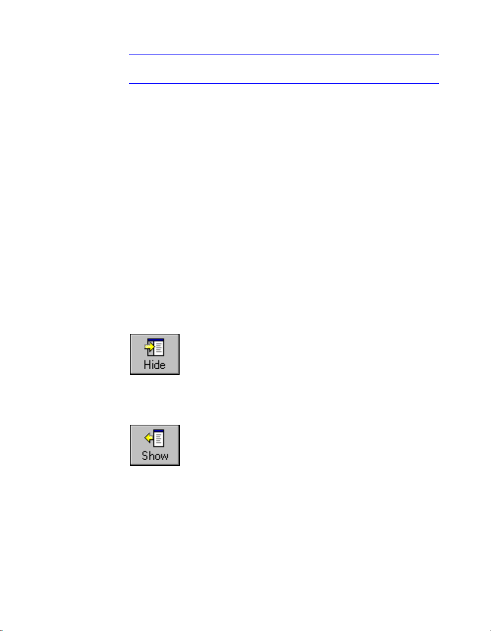
Show and Hide the Contents Pane
You can shrink the Help window to a compact size by hiding the pane that
contains Help Contents, Index, Search, Favorites, and Ask Me tabs. The compact window size is best for displaying procedures while you work.
You can expand the Help window to display the pane that contains Help
Contents, Index, Search, Favorites, and Ask Me tabs. The expanded window
size is best for locating and displaying conceptual and reference information.
Use the Help System Efficiently | 9
Page 26

Get Additional Help
You can access several additional sources of help:
■ Press F1 from within a command, system variable, or dialog box. Dis-
plays complete information from the Command Reference.
■ Choose the question mark button in many dialog boxes. Displays a
description of the dialog box option you select.
■ View the product Readme topic in Help. Displays late-breaking informa-
tion about this product.
Other resources help you get information about Autodesk products and assistance with your AutoCAD questions.
■ Autodesk website. Access http://www.autodesk.com.
■ Local support. Check with your AutoCAD dealer or Autodesk country
office.
Use Active Assistance
The Active Assistance window provides a convenient portal to the Help system. During any command, Active Assistance displays links to the Command
Reference and to procedures that are relevent to the current command.
You can type a question in the box at the top of the Active Assistance window
and then click Ask. The Help system then displays a list of topics that are
related to your question.
Often, the guidance you get from Active Assistance is just enough to get you
started performing unfamiliar or rarely used tasks.
To display Active Assistance
■ From the Help menu, choose Active Assistance.
To navigate in Active Assistance
1 Right-click in the Active Assistance window to display the shortcut menu.
2 Choose Home, Back, or Forward to navigate in Active Assistance topics, as
you would in a web browser.
10 | Chapter 1 Find the Information You Need
Page 27

To control Active Assistance settings
1 Right-click in the Active Assistance window.
2 Choose Settings from the shortcut menu.
3 In the Active Assistance Settings dialog box, use the Show on Start check
box to determine whether you want Active Assistance to start automatically when you start AutoCAD.
■ Selecting Show on Start causes Active Assistance to start automatically.
■ Clearing Show on Start causes Active Assistance to start in an alterna-
tive manner. Select an alternative in the next step.
4 In the Active Assistance Settings dialog box, under Activation, select one
of these options to determine when you get Help from Active Assistance:
■ All commands. Active Assistance starts when you begin a command.
■ New and enhanced commands. Active Assistance starts when you
begin a command that is new or changed in this version of AutoCAD.
■ Dialogs only. Active Assistance starts when a dialog box is displayed.
■ On demand. Active Assistance starts when you choose Active Assis-
tance from the Help menu or enter
ASSIST on the command line.
5 Choose OK to close the Active Assistance Settings dialog box.
Note If you close Active Assistance, double-clicking the Active Assistance icon,
which is usually located in the system tray in the lower-right corner of your
screen, reopens the window.
To print Active Assistance information
1 Display the information you want to print in the Active Assistance
window.
2 Right-click in the Active Assistance window.
3 Choose Print from the shortcut menu.
4 In the Print dialog box, choose OK.
To disable Active Assistance
1 Right-click the Assist icon located in your system tray in the bottom right-
hand corner of your display.
2 Choose Exit.
Use Active Assistance | 11
Page 28

Learn the Product
Through Autodesk’s training programs, products, and services, you can learn
about fundamental or advanced features, and about products.
For the latest information about Autodesk training, visit http://
www.autodesk.com or contact your local Autodesk office.
Autodesk Authorized Training Centers
The Autodesk
Autodesk-authorized, instructor-led training to design professionals who use
Autodesk software. More than 1,100 ATC sites are available worldwide to
meet your needs for discipline-specific, locally based training.
Autodesk Official Training Courseware
Autodesk Official Training Courseware (AOTC) supports training organizations and customers. AOTC is authorized technical training material
developed by Autodesk for traditional 2- to 5-day, instructor-led classroom
training. You can purchase AOTC from your local reseller or distributor, or
you can order it online from the Autodesk Store at autodesk.com.
Partner Products and Services
Autodesk works together with thousands of software partners around the
world. These partners provide products and services that enhance Autodesk’s
products for design professionals. Visit the “Partner Products & Services”
page at autodesk.com for a list of resources available for your Autodesk
product and your industry.
®
Authorized Training Center (ATC® ) network delivers
Obtain Documentation Updates
You can obtain product documentation updates from the Web. To check
whether documentation updates are available, click on the link below.
Between releases of documentation updates, check here for interim documentation of known issues. You may find it helpful to add some of the
interim updates to your Favorites tab for easy reference as you work.
■ Check for updates
12 | Chapter 1 Find the Information You Need
Page 29
Receive Product Updates and Announcements
Overview of Communication Center
Communication Center provides the following kinds of announcements:
■ General Product Information. Stay informed about Autodesk company
news and product announcements; provide your feedback directly to
Autodesk.
■ Product Support Information. Get breaking news from the Product Sup-
port team at Autodesk.
■ Subscription Information and Extension Announcements. Receive
announcements and subscription program news if you are an Autodesk
subscription member (available in countries where Autodesk subscriptions are offered).
■ Articles and Tips. Be notified when new articles and tips are available on
Autodesk websites.
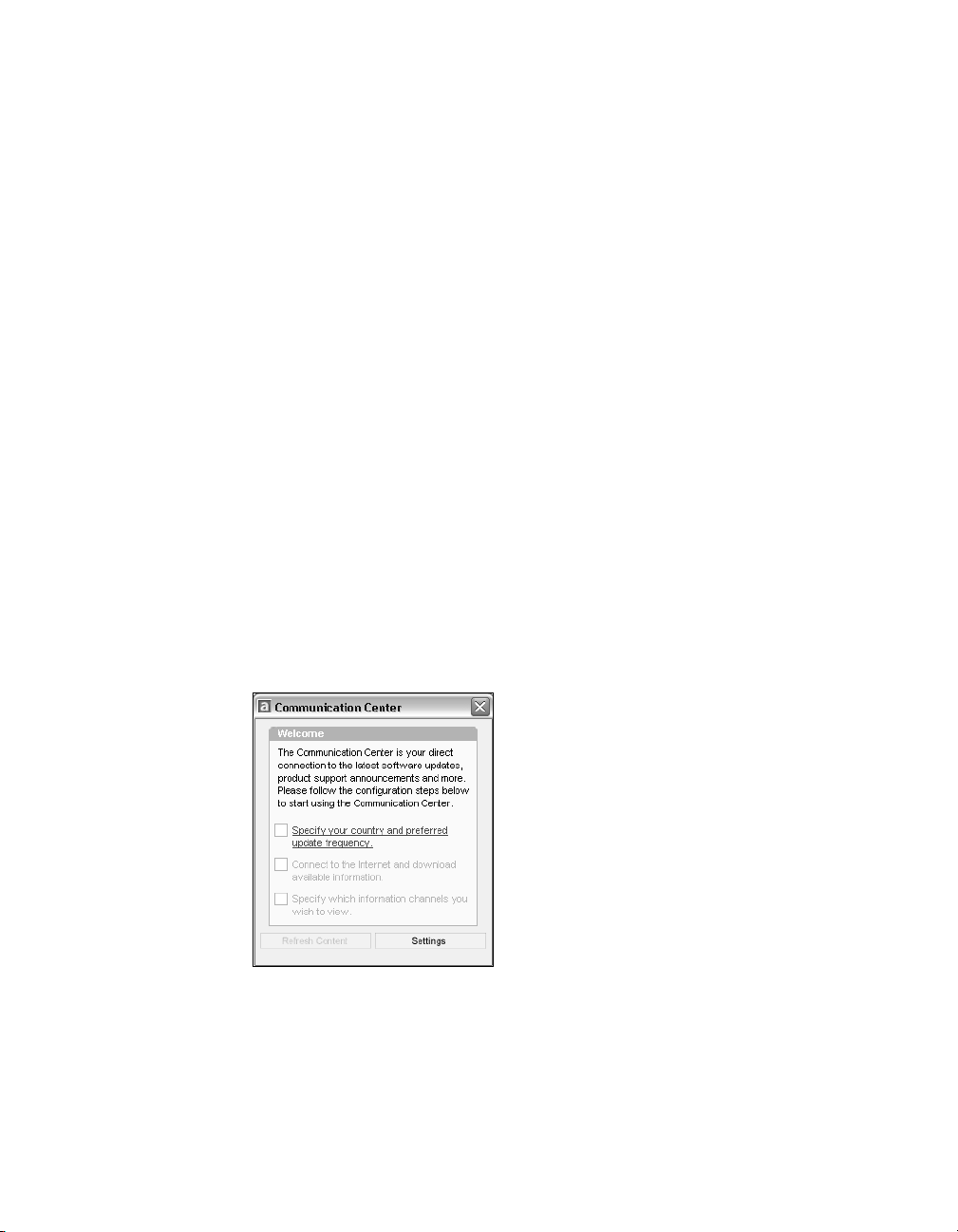
When you begin using your product, you use the Welcome wizard to set
Communication Center for your country, and for the frequency you prefer
for updates and the information channels you want displayed.
To open Communication Center, click the Communication Center icon in
the tray on the right side of the status bar.
Receive Product Updates and Announcements | 13
Page 30

Communication Center Online Privacy
Communication Center is an interactive feature that must be connected to
the Internet to deliver content and information. Each time Communication
Center is connected, it sends information to Autodesk so that the correct
information can be returned. All information is sent anonymously to maintain your privacy.
The following information is sent to Autodesk:
■ Product Name. The name of the product in which you are using Commu-
nication Center
■ Product Release Number. The version of the product
■ Product Language. The language version of your product
■ Country. The country that was specified in the Communication Center
settings
Autodesk compiles statistics using the information sent from Communications Center to monitor how it is being used and how it can be improved.
Autodesk will maintain information provided by or collected from you in
accordance with Autodesk’s published privacy policy, which is available on
http://www.autodesk.com/privacy.
Turn Communication Center On or Off
The CAD Manager Control utility turns Communication Center on and off.
For example, if you want to prevent Communication Center from sending
information to Autodesk, you can turn it off. Information about how to use
the utility is available by installing and running the utility, and then clicking
Help in the CAD Manager Control Utility window.
To install the utility, double-click setup.exe on the product CD. In the CD
Browser, click the Network Deployment tab, and under Install Supplemental
Tools, click Autodesk CAD Manager Tools 2.0. Under Autodesk CAD Manager
Tools 2.0, click Install. After you install the CAD Manager Control utility, you
access it from the Start menu (Windows).
Customize Program Update and Announcement Options
After installing your Autodesk product, you configure Communication
Center with the Welcome wizard to specify the information you want sent to
you.
■ Country. Specifies your country so that Communication Center can
provide information that is designed specifically for your location.
14 | Chapter 1 Find the Information You Need
Page 31
■ Update Frequency. Specifies how often you want Communication
Center to synchronize with Autodesk servers.
■ Balloon Notification. Turns on ballon notification so that Communica-
tion Center balloon messages are displayed above the status bar when a
new announcement is received. If the balloon notifications have been disabled in the tray settings, the Balloon Notification setting in the Communication Center is ignored.
■ Channels. Specifies the information that you want displayed in
Communication Center.
To customize Communication Center options
1 Click the Communication Center icon located in the tray on the right side
of the status bar.
2 In the Communication Center window, click Settings.
3 In the Configuration Settings dialog box, choose the settings and options
that you want to use and then click Apply.
4 Click OK to close the Configuration Settings dialog box and then close the
Communication Center window.
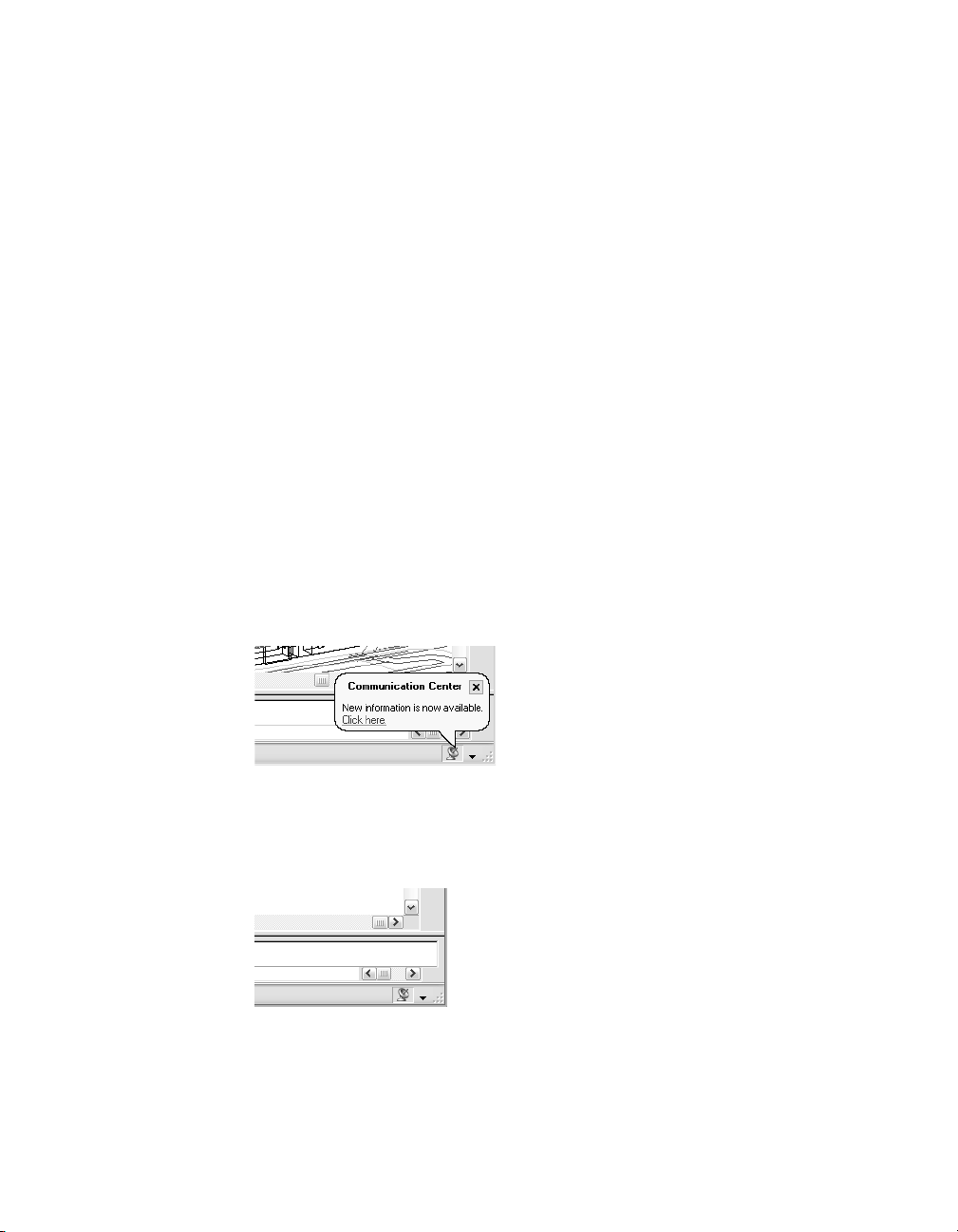
Receive New Information Notifications
Whenever new information is available, Communication Center notifies you
by displaying a balloon message above the status bar.
Click the balloon message to open the Communication Center window. If
you prefer to be notified by the Communication Center icon, you can turn
off Balloon Notification in the Configuration Settings dialog box of Communication Center.
Receive Product Updates and Announcements | 15
Page 32

If no Communication Center icon is shown on the status bar, see your
network administrator.
To open the Communication Center window
■ Click the Communication Center icon located in the tray on the right side
of the status bar.
View the Product Readme
You can find late-breaking information about this software in the Readme. It
is suggested that you read through the Readme for information about recommended hardware, updated installation instructions, and known software
problems. The Readme also contains details about Autodesk trademarks.
■ View the Readme
16 | Chapter 1 Find the Information You Need
Page 33

Part 1
The User Interface
Chapter 2 Menus, Toolbars and Tool Palettes 19
Chapter 3 The Command Window 35
Chapter 4 DesignCenter 45
Chapter 5 Customize the Drawing Environment 61
Chapter 6 Pointing Devices 69
17
Page 34

18
Page 35

Menus, Toolbars and Tool
Palettes
AutoCAD® provides menus, shortcut menus, toolbars,
and tool palettes for access to frequently used
commands, settings, and modes. The Standard, Object
Properties, Draw, and Modify toolbars are displayed by
default. Shortcut menus display commands that are
relevant to your current activity. Tool palettes provide
an efficient method for organizing and placing blocks
and hatches.
In this chapter
■ To o l P a le t te s
■ To o l b a r s
■ The Menu Bar
■ Shortcut Menus
■ The Object Snap Menu
19
Page 36

Tool Palettes
Tool palettes are tabbed areas within the Tool Palettes window that provide
an efficient method for organizing, sharing, and placing blocks and hatches.
Tool palettes can also contain custom tools provided by third-party
developers.
Insert Blocks and Hatches Using Tool Palettes
Tool palettes are tabbed areas within the Tool Palettes window. You can place
blocks and hatches that you use often on a tool palette. When you need to
add a block or a hatch to a drawing, drag it from the tool palette onto your
drawing.
Blocks and hatches that reside on a tool palette are called tools, and several
tool properties including scale, rotation, and layer can be set for each tool
individually.
Blocks that are placed with this method often must be rotated or scaled after
they are placed. You can use object snaps when dragging blocks from a tool
palette, however grid snap is suppressed during dragging.
Scale Blocks Automatically
When a block is dragged from a tool palette into a drawing, it is scaled automatically according to the ratio of units defined in the block and defined in
the current drawing. For example, if the current drawing uses meters as its
units and a block is defined using centimeters as its units, the ratio of the
units is 1 m/100 cm. When the block is dragged into the drawing, it is
inserted at 1/100 scale.
Note In the Options dialog box, User Preferences tab, the Source Content
Units and Target Drawing Units settings are used when, either in the source
block or the target drawing, the Drag-and-Drop Scale is set to Unitless.
See Also
“Control Tool Properties” on page 23
“Customize Tool Palettes” on page 25
“Add Content with DesignCenter” on page 51
20 | Chapter 2 Menus, Toolbars and Tool Palettes
Page 37

To display the Tool Palettes window
■ On the Tools menu, click Tool Palettes Window. Alternatively, you can
CTRL+3.
press
Standard toolbar
Command line
TOOLPALETTES
Change Tool Palette Settings
The options and settings for tool palettes are accessible from shortcut menus
in different areas on the Tool Palettes window. These settings include
■ Auto-hide. The Tool Palettes window can automatically roll open or roll
away when your cursor moves over the title bar on the Tool Palettes
window.
■ Transparency. The Tool Palettes window can be made transparent so it
does not obscure objects under it. (Transparency is not available to
Microsoft
®
Windows NT users.)
Tool Palettes | 21
Page 38
■ Views. The display style and size of the icons in a tool palette can be
changed.
You can dock the Tool Palettes window on the right or left edge of the application window. Press the
CTRL key to prevent docking as you move the Tool
Palettes window.
Tool palette settings are saved with your AutoCAD profile.
To change the roll-over behavior of the Tool Palettes window
■ Click the Auto-Hide button at the bottom of the title bar of the Tool Pal-
ettes window.
Roll-over behavior is on.
Roll-over behavior is off.
Note Roll-over behavior is available only when the Tool Palettes window is
undocked.
To change the transparency of the Tool Palettes window
1 Right-click the title bar of the Tool Palettes window, and then click Trans-
parency on the displayed menu.
2 In the Transparency dialog box, adjust the level of transparency for the
Tool Palettes window. Click OK.
Note Transparency is available only when the Tool Palettes window is
undocked. Transparency is not available to Microsoft Windows NT users.
22 | Chapter 2 Menus, Toolbars and Tool Palettes
Page 39

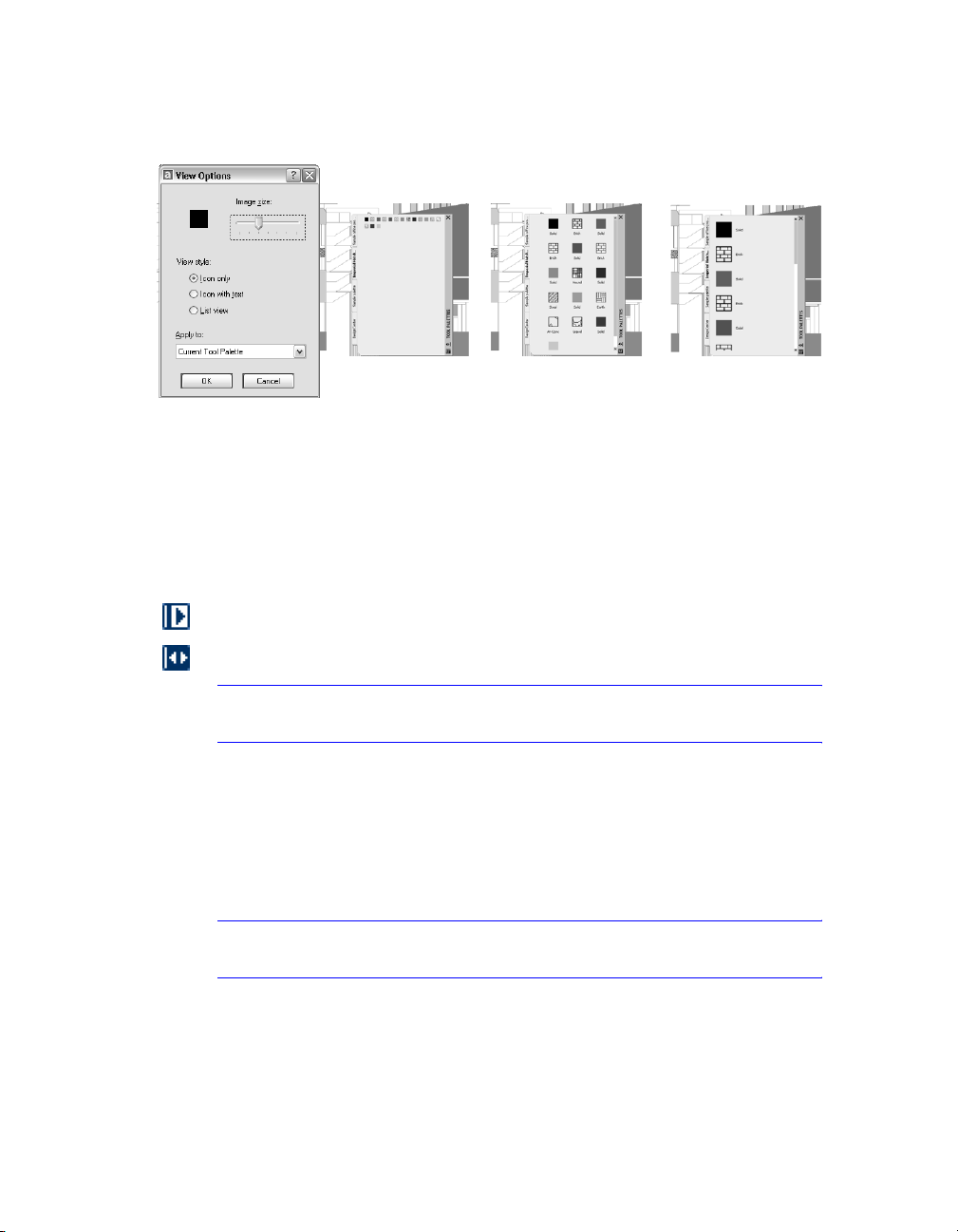
To change the icon display style in the Tool Palettes window
1 Right-click the blank area of the Tool Palettes window, and then click View
Options on the displayed menu.
2 In the View Options dialog box, click the icon display option that you
want to set. You can also change the size of the icons.
3 Click the list box under Apply To, and then click either Current Tool
Palette or All Tool Palettes. Click OK.
Control Tool Properties
You can change the insertion properties or pattern properties of any tool on
a tool palette. For example, you can change the insertion scale of a block or
the angle of a hatch pattern.
To change these tool properties, right-click a tool and click Properties on the
shortcut menu. Then you change the tool’s properties in the Tool Properties
dialog box. The Tool Properties dialog box has two categories of properties—
the Insert or Pattern properties category, and the General properties category.
■ Insert or Pattern properties. Control object-specific properties such as
scale, rotation, and angle.
■ General properties. Override the current drawing property settings such
as layer, color, and linetype.
Tool Palettes | 23
Page 40

Update the Icon for a Tool
Icons in tool palettes are not automatically updated if the block or hatch
changes. If you change a block or hatch definition you can update its icon in
a tool palette. In the Tool Properties dialog box, change the entry in the
Source File field for blocks or the Pattern name field for hatches, and then
change the entry back again. This forces an update of the icon for that tool.
Alternatively, you can delete the tool and then replace it using DesignCenter.
Specify Overrides for Tool Properties
In some cases, you may want to assign specific property overrides to a tool.
For example, you may want a hatch to be placed automatically on a pre-specified layer, regardless of the current layer setting. This feature can save you
time and reduce errors by setting properties automatically when creating
certain objects.
The Tool Properties dialog box provides fields for each potential property
override.
Layer property overrides affect color, linetype, lineweight, plot style, and
plot. Layer property overrides are resolved as follows:
■ If a layer is missing from the drawing, that layer is created automatically.
■ If a layer to which you are dragging a block or hatch is currently turned
off or frozen, the layer is temporarily turned on or thawed.
To display the properties of a tool on a tool palette
1 On a tool palette, right-click a tool and then click Properties on the short-
cut menu.
2 In the Tool Properties dialog box, use the scroll bar to view all tool
properties.
You can also resize the Tool Properties dialog box or expand and collapse
the property categories by clicking the double arrow buttons.
3 Click OK.
To change a property of a tool on a tool palette
1 On a tool palette , right-click a tool and then click Properties on the short-
cut menu.
2 In the Tool Properties dialog box, use the scroll bar to view all tool prop-
erties. Click any property field and specify the new value or setting.
■ Properties listed under the Insert or Pattern category control object-spe-
cific properties such as scale, rotation, and angle.
24 | Chapter 2 Menus, Toolbars and Tool Palettes
Page 41

■ Properties listed under the General category override the current draw-
ing property settings such as layer, color, and linetype.
You can also resize the Tool Properties dialog box or expand and collapse
the property categories by clicking the arrow buttons.
3 Click OK.
Customize Tool Palettes
You can create new tool palettes using the Properties button on the title bar
of the Tool Palettes window. Add tools to a tool palette with the following
methods:
■ Drag drawings, blocks, and hatches from DesignCenter to the tool palette.
Drawings that are added to a tool palette are inserted as blocks when
dragged into the drawing.
■ Use Cut, Copy, and Paste to move or copy tools from one tool palette to
another.
■ Create a pre-populated tool palette tab by right-clicking a folder, a draw-
ing file, or a block in the DesignCenter tree view, and then clicking Create
Tool Palette on the shortcut menu.
Tool Palettes | 25
Page 42

Note For block tools on tool palettes, the source drawing files must always be
accessible. If a source drawing file is moved to a different folder, you must modify
the block tool that references it by right-clicking the block tool and, in the Tool
Properties dialog box, specifying the new source file folder.
Once tools are placed in a tool palette, you can rearrange them by dragging
them within the tool palette.
A tool palette tab can be moved up and down the list of tabs from the tool
palette shortcut menu, or from the Tool Palettes tab of the Customize dialog
box. Similarly, you can delete tool palettes that you no longer need. Tool palettes that are deleted are lost unless they are first saved by exporting them to
a file. You can control the path to your tool palettes on the Files tab in the
Options dialog box. This path can be to a shared network location.
Note If a tool palette file is set with a read-only attribute, a lock icon displays
in a lower corner of the tool palette. This indicates that the tool palette cannot
be modified beyond changing its display settings and rearranging the icons.
To create a tool palette from a folder or a drawing
1 If DesignCenter is not already open, on the Tools menu, click
DesignCenter.
2 In the DesignCenter tree view or the content area, right-click a folder,
drawing file, or block.
3 On the shortcut menu, click Create Tool Palette.
A new tool palette is created that contains all the blocks and hatches in
the selected folder or drawing.
Standard toolbar
Command line
ADCENTER
Save and Share Tool Palettes
You can save and share a tool palette by exporting it or importing it as a tool
palette file. You import and export a tool palette from the Tool palettes tab
on the Customize dialog box. Tool palette files have an .xtp file extension.
26 | Chapter 2 Menus, Toolbars and Tool Palettes
Page 43

The default path for tool palette files is set on the Files tab of the Options dialog box under Tool Palettes File Locations.
Note If a tool palette file is set with a read-only attribute, a lock icon displays
in a lower corner of the tool palette. This indicates that the tool palette cannot
be modified beyond changing its display settings and rearranging the icons.
Toolbars
Toolbars contain buttons that start commands. When you move the pointing device over a toolbar button, the tooltip displays the name of the button.
Buttons with a small black triangle in the lower-right corner have flyouts that
contain related commands. With the cursor over the icon, hold down the
pick button until the flyout appears.
The Standard toolbar at the top of the drawing area is displayed by default.
This toolbar is similar to those found in Microsoft Office programs. It contains frequently used AutoCAD commands such as
well as Microsoft Office standard commands such as New, Open, and Save.
Display, Dock, and Resize Toolbars
AutoCAD initially displays several toolbars:
■ Standard toolbar
■ Styles toolbar
■ Layers toolbar
■ Properties toolbar
■ Draw toolbar
■ Modify toolbar
DIST, PAN, and ZOOM, as
You can display or hide these four and additional toolbars, and you can
create your own toolbars. A toolbar can be floating or docked. A floating toolbar is located anywhere in the drawing area of the AutoCAD window, and
you can drag it to a new location, resize it, or dock it. A docked toolbar is
attached to any edge of the drawing area. While a toolbar is docked, it cannot
be resized. You can move a docked toolbar by dragging it to a new docking
location.
See Also
“Create Custom Toolbars” in the Customization Guide
To o l b a r s | 27
Page 44

To display a toolbar
1 From the View menu, choose Toolbars.
2 In the Customize dialog box, Toolbars tab, select the name of the toolbar
you want to show.
3 Choose Close.
Shortcut menu You can also display a toolbar by right-clicking any toolbar
button and choosing a toolbar from the shortcut menu.
Command line
CUSTOMIZE
To dock a toolbar
1 Position the cursor on the name of the toolbar or in any blank area, and
hold down the button on your pointing device.
2 Drag the toolbar to a docking location at the top, bottom, or either side of
the drawing area.
3 When the outline of the toolbar appears in the docking area, release the
button.
To place a toolbar in a docking region without docking it, hold down
CTRL
as you drag.
To undock a toolbar
1 Position the cursor on the double bars at the end of the toolbar, and hold
down the button on your pointing device.
2 Drag the toolbar away from its docked location and release the button.
To resize a toolbar
1 Position the cursor on the edge of a floating toolbar until the cursor
changes to a horizontal or vertical double arrow.
2 Hold down the button and move the cursor until the toolbar is in the
shape you want.
To close a toolbar
1 If the toolbar is docked, undock it.
2 Click the Close button in the upper-right corner of the toolbar.
28 | Chapter 2 Menus, Toolbars and Tool Palettes
Page 45

The Menu Bar
Menus are available from the menu bar at the top of the AutoCAD drawing
area. You can choose menu options in the following ways:
■ Click the menu name to display a list of options. Click the option to
choose it, or press
ENTER.
■ Press ALT and then enter the underlined letter in the menu name. For
example, to open a new drawing, press
menu. Then press
The default menu file is acad.mnu. You can specify a different menu (for
example, a menu you have customized) in the Options dialog box, Files tab.
See Also
“Create Pull-Down and Shortcut Menus” in the Customization Guide
To use a menu
Choose one of the following methods:
■ On the menu bar, click a menu name to display a list of options. On the
menu, either click an option or use the
list, and then press
■ Press ALT and press the underlined letter in the menu name. Then press
the underlined letter in the option name. For example, to open a new
drawing, press
New.
DOWN ARROW to move down the list and then press
ALT and press F to open the File
ENTER to choose the highlighted option New.
DOWN ARROW to move down the
ENTER.
ALT and press F to open the File menu. Then press N for
Shortcut Menus
Shortcut menus give you quick access to commands relevant to your current
activity. You can display different shortcut menus when you right-click
different areas of the screen, including
■ Within the drawing area with one or more objects selected
■ Within the drawing area without any objects selected
■ Within the drawing area during a command
■ Within the text and command windows
■ Within areas and on icons in DesignCenter
■ Within areas and on text in the Multiline Text Editor
The Menu Bar | 29
Page 46

■ On a toolbar or palette
■ On the Model or layout tabs
■ On the status bar or the status bar buttons
Shortcut menus typically include options to
■ Repeat the last command entered
■ Cancel the current command
■ Cut and copy to the Clipboard and paste from the Clipboard
■ Select a different command option
■ Display a dialog box, such as Options or Customize
■ Undo the last command entered
If text has been entered on the command line, right-clicking automatically
executes the text as a command without displaying the shortcut menu.
You can customize right-click behavior to be time-sensitive, so that a quick
right-click acts the same as pressing
ENTER, and a longer right-click displays
a shortcut menu.
Shortcut menus can be customized by changing the acad.mnu file.
See Also
“Create Shortcut Menus” in the Customization Guide
To display a shortcut menu
1 At the Command prompt, move the cursor over an area, feature, or icon.
2 Right-click your mouse, or press the equivalent button on your pointing
device.
A shortcut menu relevant to the cursor location is displayed. If one or
more objects are selected when you right-click in the drawing area, an
editing-oriented shortcut menu is displayed. You can also display a shortcut menu during
PAN or ZOOM.
To turn off shortcut menus in the drawing area
1 From the Tools menu, choose Options.
2 In the Options dialog box, choose the User Preferences tab.
3 Under Windows Standard Behavior, clear Shortcut Menus in Drawing
Area.
4 To control Default, Edit, and Command shortcut menus individually,
select Shortcut Menus in Drawing Area, and then choose Right-Click
Customization.
30 | Chapter 2 Menus, Toolbars and Tool Palettes
Page 47

5 In the Right-Click Customization dialog box under Default Mode or Edit
Mode, select one of the following options to control what happens when
you right-click in the drawing area and no command is in progress:
■ Repeat Last Command. Repeats the last command. Selecting this
option turns off the Default and Edit shortcut menus. Right-clicking is
the same as pressing
■ Shortcut Menu. Displays the Default or Edit shortcut menu.
ENTER.
6 Under Command Mode, select one of the following options to determine
what happens when you right-click in the drawing area while a command
is in progress:
■ Enter. Turns off the Command shortcut menu. Right-clicking is the
same as pressing
■ Shortcut Menu: Always Enabled. Displays the Command shortcut
ENTER.
menu.
■ Shortcut Menu: Enabled When Command Options Are Present.
Displays the Command shortcut menu only when options are
currently available in the command line prompt. In a command
prompt, options are enclosed in square brackets. If no options are
available, right-clicking is the same as pressing
ENTER.
In addition to turning the Default, Edit, and Command shortcut menus
on and off, you can customize the options that are displayed on them. For
example, you can add options to the Edit shortcut menu that are displayed only when circles are selected.
To turn on time-sensitive right-click behavior
1 On the Tools menu, click Options.
2 In the Options dialog box, select the User Preferences tab.
3 Under Windows Standard Behavior, click Right-Click Customization.
4 Select Turn on Time-Sensitive Right-Click.
You can specify the duration of the longer click. The default is 250 milliseconds
5 Click Apply & Close.
6 In the Options dialog box, click OK.
Command line
OPTIONS
Shortcut Menus | 31
Page 48

To control the display of icons and notifications in the status bar tray
1 Click the arrow at the right end of the status bar and then click Tray
Settings.
2 In the Tray Settings dialog box, select or clear the following display
options:
■ Display Icons from Services. Displays the tray at the right end of the sta-
tus bar and displays icons from services. When this option is cleared,
the tray is not displayed.
■ Display Notifications from Services. Displays notifications from ser-
vices. When the Display Icons from Services option is cleared, this
option is unavailable.
3 If Display Notifications from Services is selected, set a time for a notifica-
tion to be displayed or select Display Until Closed.
Shortcut menu Right-click an empty area on the status bar and click Tray
Settings.
Command line
TRAYSETTINGS
To control the display of buttons on the status bar
■ Click the arrow at the right end of the status bar and click any button
name to change the display.
Items with a check mark next to them are displayed on the status bar.
Shortcut menu Right-click an empty area on the status bar and click a
button name.
To control the display of coordinates on the status bar
■ Click the arrow at the right end of the status bar and click Cursor Coordi-
nate Values.
Items with a check mark next to them are displayed on the status bar.
Shortcut menu Right-click an empty area on the status bar and click Cursor
Coordinate Values.
32 | Chapter 2 Menus, Toolbars and Tool Palettes
Page 49

The Object Snap Menu
The object snap menu is displayed at your cursor location when you hold
SHIFT and click the right mouse button or the equivalent button on
down
another pointing device.
The default object snap menu lists object snaps and tracking options. If you
want to change the options, you can customize the acad.mnu file.
See Also
“Create Pull-Down and Shortcut Menus” in the Customization Guide
To display the object snap menu
1 Enter any command that prompts you to specify a point. For example,
enter line.
2 At the From Point prompt, hold down
The object snap menu is displayed, and you can choose an object snap
option.
SHIFT and right-click.
The Object Snap Menu | 33
Page 50

34
Page 51

The Command Window
Commands, system variables, options, messages, and
prompts are displayed in a dockable and resizable
window called the command window. The bottom line
of the command window is called the command line. The
command line displays the operation in progress and
provides an inside view of exactly what the program is
doing.
In this chapter
■ Enter Commands on the
Command Line
■ Enter System Variables on the
Command Line
■ Navigate and Edit Within the
Command Window
■ Switch Between Dialog Boxes
and the Command Line
■ Dock and Resize the Command
Window
35
Page 52

Enter Commands on the Command Line
To enter a command by using the keyboard, type the full command name on
the command line and press
device.
Some commands also have abbreviated names. For example, instead of
entering circle to start the
command names are called command aliases and are defined in the acad.pgp
file. To define your own command aliases, see “Create Command Aliases” in
the Customization Guide.
Specify Command Options
When you enter commands on the command line, AutoCAD displays either
a set of options or a dialog box. For example, when you enter circle at the
Command prompt, the following prompt is displayed:
Specify center point for circle or [3P/2P/Ttr (tan, tan, radius)]:
You can specify the center point either by entering X,Y coordinate values or
by using the pointing device to click a point on the screen.
To choose a different option, enter the letters capitalized in one of the
options in the brackets. You can enter uppercase or lowercase letters. For
example, to choose the three-point option (3P), enter 3p.
Execute Commands
To execute commands, press
device after entering command names or responses to prompts. The instructions in Help assume this step and do not specifically instruct you to press
ENTER after each entry.
ENTER or SPACEBAR, or right-click your pointing
CIRCLE command, you can enter c. Abbreviated
SPACEBAR or ENTER, or right-click your pointing
Repeat and Cancel Commands
If you want to repeat a command that you have just used, press
SPACEBAR, or right-click your pointing device at the Command prompt.
You also can repeat a command by entering multiple, a space, and the
command name, as shown in the following example:
Command: multiple circle
To cancel a command in progress, press
36 | Chapter 3 The Command Window
ENTER or
ESC.
Page 53

Interrupt a Command with Another Command or System Variable
Many commands can be used transparently: that is, they can be entered on
the command line while you use another command. Transparent commands
frequently change drawing settings or display options, for example,
ZOOM. In the Command Reference, transparent commands are designated by
GRID or
an apostrophe in front of the command name.
To use a command transparently, choose its toolbar button or enter an apostrophe (') before entering the command at any prompt. On the command
line, double angle brackets (>>) precede prompts that AutoCAD displays for
transparent commands. After you complete the transparent command, the
original command resumes. In the following example, you turn on the dot
grid and set it to one-unit intervals while you draw a line, and then you
continue drawing the line.
Command: line
Specify first point: 'grid
>>Specify grid spacing (X) or [ON/OFF/Snap/Aspect] <0.000>: 1
Resuming
LINE command
Specify first point:
Commands that do not select objects, create new objects, or end the drawing
session usually can be used transparently. Changes made in dialog boxes that
you have opened transparently cannot take effect until the interrupted command has been executed. Similarly, if you reset a system variable transparently, the new value cannot take effect until you start the next command.
See Also
“Create Shortcut Keys” in the Customization Guide
To copy a command you have already used
1 Highlight the text to be copied.
2 Position the cursor over the command or text window and right-click.
3 Choose Copy from the shortcut menu.
4 Position the cursor over the command or text window and right-click.
5 Choose Paste from the shortcut menu.
6 Press
Command line
ENTER or SPACEBAR.
COPYCLIP, PASTECLIP
Enter Commands on the Command Line | 37
Page 54

Enter System Variables on the Command Line
System variables are settings that control how certain commands work. They
can turn on or turn off modes such as Snap, Grid, or Ortho. They can set
default scales for hatch patterns. They can store information about the
current drawing and about AutoCAD configuration. Sometimes you use a
system variable in order to change a setting. At other times you use a system
variable to display the current status.
For example, the
and off when you change the value. In this case, the
variable is functionally equivalent to the
system variable that stores the current date. You can display this value, but
you cannot change it.
You can examine or change a system variable's setting transparently, that is,
while using another command; however, new values may not take effect
until the interrupted command ends.
To change the setting of a system variable
1 At the Command prompt, enter the system variable name. For example,
enter gridmode to change the grid setting.
2 To change the status of
current value of the system variable, press
To see a complete list of system variables
1 At the Command prompt, enter setvar.
2 At the Variable Name prompt, enter ?.
3 At the Enter Variable(s) to List prompt, press
Command line
GRIDMODE system variable turns the dot grid display on
GRIDMODE system
GRID command. DATE is a read-only
GRIDMODE, enter 1 for on or 0 for off. To retain the
ENTER.
ENTER.
SETVAR
38 | Chapter 3 The Command Window
Page 55

Navigate and Edit Within the Command Window
You can navigate and edit text in the command window to correct or repeat
commands. Use the standard keys:
■ UP, DOWN, LEFT ARROW, and RIGHT ARROW
■ INS, DEL
■ PAGE UP, PAGE DOWN
■ HOME, END
■ BACKSPACE
You can repeat any command used in the current session by cycling through
the commands in the command window with
and pressing
the Clipboard. Pressing
command window.
If you right-click in the command window or text window, AutoCAD displays a shortcut menu from which you can access the six most recently used
commands, copy selected text or the entire command history, paste text, and
access the Options dialog box.
For most commands, a command line with two or three lines of previous
prompts, called the command history, is sufficient for viewing and editing.
To see more than one line of command history, you can scroll through the
history or resize the command window by dragging its border. For commands with text output, such as
window, or you can press
ENTER. By default, pressing CTRL+C copies highlighted text to
CTRL+V pastes text from the Clipboard to the text or
LIST, you might need a larger command
F2 to use the text window.
UP ARROW and DOWN ARROW
Use the Text Window
The text window is a window similar to the command window in which you
can enter commands and view prompts and messages. The text window displays a complete command history for the current AutoCAD session. Use the
text window to view lengthy output of commands such as LIST, which dis-
plays detailed information about objects you select. To move forward and
backward in the command history, you can click the scroll arrows along the
right edge of the window.
Navigate and Edit Within the Command Window | 39
Page 56

Press SHIFT with a key to highlight text. For example, press SHIFT+HOME in
the text window to highlight all text from the cursor location to the beginning of the line.
To copy all the text in the text window to the Clipboard, use the
COPYHIST
command.
See Also
“Dock and Resize the Command Window” on page 42
To display the text window
■ From within the drawing area, press F2.
The text window is displayed in front of the AutoCAD drawing area.
Command line
TEXTSCR
To close the text window
■ From within the text window, press F2.
The text window is closed. You can also close the text window using the standard Windows controls.
Command line
GRAPHSCR
To copy text from the text window to the command line
1 If the text window is not displayed, press
F2 to display it.
2 Select the text you want to copy.
3 Right-click in the command window or text window and choose Paste to
Command Line.
AutoCAD copies the text to the Clipboard and pastes it on the command
line. After you press ENTER, AutoCAD executes the commands in
sequence, like a script. You can also use
CTRL+C and CTRL+V to copy and
paste text.
40 | Chapter 3 The Command Window
Page 57

Switch Between Dialog Boxes and the Command Line
Some functions are available both on the command line and in a dialog box.
In many cases, you can enter a hyphen before the command to suppress the
dialog box and display prompts on the command line instead. For example,
entering layer on the command line displays the Layer Properties Manager.
Entering -layer on the command line displays the equivalent command line
options. Suppressing the dialog box is useful for compatibility with earlier
versions of AutoCAD and for using script files. There may be slight differences between the options in the dialog box and those available on the
command line.
These system variables also affect the display of dialog boxes:
■ ATTDIA controls whether INSERT uses a dialog box for attribute value entry.
■ CMDNAMES displays the name (in English) of the currently active com-
mand and transparent command.
■ EXPERT controls whether certain warning dialog boxes are displayed.
■ FILEDIA controls the display of dialog boxes used with commands that
read and write files. For example, if
Save Drawing As dialog box. If
on the command line. The procedures in this documentation assume that
FILEDIA is set to 1. Even when FILEDIA is set to 0, you can display a file
dialog box by entering a tilde (~) at the first prompt.
FILEDIA is set to 1, SAVEAS displays the
FILEDIA is set to 0, SAVEAS displays prompts
FILEDIA and EXPERT are useful when you use scripts to run commands.
To use the command line version of a command
■ For most commands, enter minus (-) in front of the command.
■ For dialog boxes that open and save files, set the FILEDIA system variable
to 0.
Switch Between Dialog Boxes and the Command Line | 41
Page 58

Dock and Resize the Command Window
By default, the command window is docked. The docked command window
is the same width as the AutoCAD window. If text that is entered becomes
longer than the width of the command line, the window pops up in front of
the command line to show the full text of the line.
You can resize the window vertically by dragging the splitter bar, which is
located on the top edge of the window when it is docked on the bottom and
at the bottom edge of the window when it is docked at the top.
Undock the command window by dragging it away from the docking region.
When you undock the window, the floating window is the size it was before
you undocked it. You can move the floating command window anywhere on
the screen and resize its width and height with the pointing device.
Dock the command window by dragging it until it is over the top or bottom
docking regions of the AutoCAD window.
To float the command window
■ Click the move handle on the left edge of the docked command window
and drag the command window away from the docking region until it has
a thick outline. Then drop it in the drawing area of the AutoCAD window.
To make the floating command window transparent
1 Right-click in the floating command window, and click Transparency.
2 In the Transparency dialog box, move the slider to the left to make the
command window less transparent and to the right to make it more
transparent.
The range is from opaque to transparent. When the Turn Off Transparency
for All Palettes option is selected, the command window cannot be made
transparent.
Note Transparency is not available to Microsoft
42 | Chapter 3 The Command Window
®
Windows NT users.
Page 59

To dock the command window
■ Click the title bar and drag the command window until it is over the top
or bottom docking regions of the AutoCAD window.
To resize the command window when it is docked
1 Position the cursor over the horizontal splitter bar so that the cursor
appears as a double line and arrows.
2 Drag the splitter bar vertically until the command window is the size you
want it to be.
Dock and Resize the Command Window | 43
Page 60

44
Page 61

DesignCenter
With DesignCenter,™ you can organize access to blocks,
hatches, xrefs, and other drawing content. You can drag con-
tent from any source drawing to your current drawing. You
can drag drawings, blocks, and hatches to a tool palette.
Source drawings can be on your computer, on a network loca-
tion, or on a website. In addition, if you have multiple draw-
ings open, you can use DesignCenter to streamline your draw-
ing process by copying and pasting other content, such as
layer definitions, layouts, and text styles between drawings.
In this chapter
■ Overview of DesignCenter
■ Understand the DesignCenter
Window
■ Access Content with
DesignCenter
■ Add Content with
DesignCenter
■ Retrieve Content from the
Web with DesignCenter Online
45
Page 62
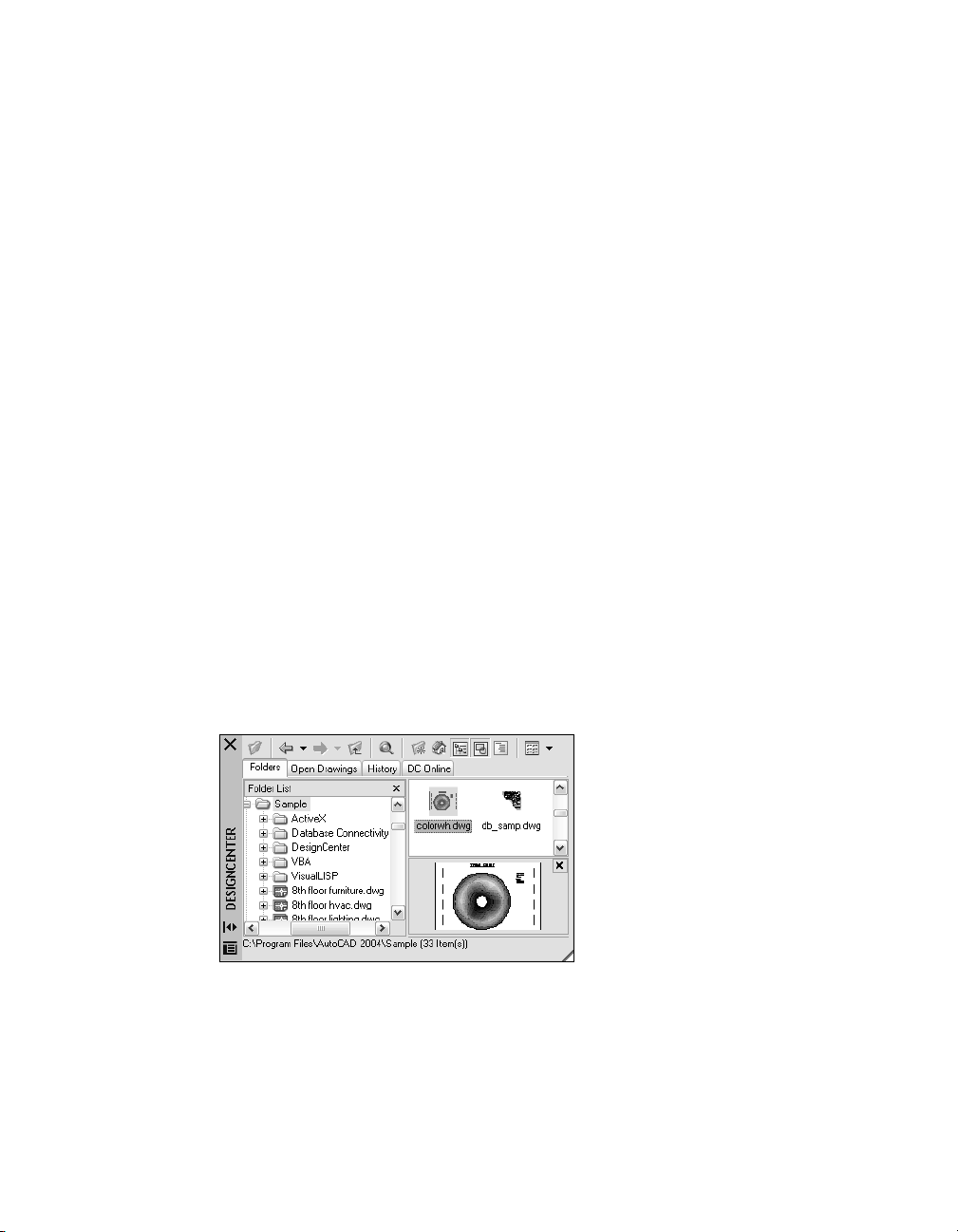
Overview of DesignCenter
With DesignCenter, you can
■ Browse for drawing content such as drawings or symbol libraries on your
computer, on a networked drive, and on a web page
■ View definition tables for named objects such as blocks and layers in any
drawing file and then insert, attach, or copy and paste the definitions into
the current drawing
■ Update (redefine) a block definition
■ Create shortcuts to drawings, folders, and Internet locations that you
access frequently
■ Add content such as xrefs, blocks, and hatches to a drawing
■ Open drawing files in a new window
■ Drag drawings, blocks, and hatches to a tool palette for convenient access
Understand the DesignCenter Window
You can control the size, location, and appearance of DesignCenter.
The Organization of the DesignCenter Window
The DesignCenter window is divided into the tree view on the left side and
the content area on the right side. Use the tree view to browse sources of content and to display content in the content area. Use the content area to add
items to a drawing or to a tool palette.
Undocked, the DesignCenter window is displayed as shown.
Below the content area, you can also display a preview or a description of a
selected drawing, block, hatch pattern, or xref. A toolbar at the top of the
window provides several options and operations.
46 | Chapter 4 DesignCenter
Page 63

Control the Size, Location, and Appearance of DesignCenter
You can control the size, location and appearance of DesignCenter.
■ Resize DesignCenter by dragging the bar between the content area and the
tree view or by dragging an edge as you would any other window.
■ Dock DesignCenter by dragging it over the right or left docking regions of
the AutoCAD window until it snaps into the docked position. You can also
dock the DesignCenter window by double-clicking its title bar.
■ Undock DesignCenter by dragging the area above the toolbar away from
the docking region. Pressing
■ Change the automatic roll-over behavior of DesignCenter by clicking the
CTRL while dragging prevents docking.
Auto-hide button on the DesignCenter title bar.
When the DesignCenter roll-over option is turned on, the DesignCenter tree
view and content area disappear when you move your cursor off the DesignCenter window, leaving only the title bar. When you move your cursor over
the title bar, the DesignCenter window is restored.
Several options are available on the shortcut menu that is displayed when
you right-click on the DesignCenter title bar.
The DesignCenter Toolbar
The DesignCenter toolbar controls navigation and display of information in
the tree view and the content area. For information about these buttons, see
ADCENTER command. The same navigation and display options are avail-
the
able on a shortcut menu. Right-click in the DesignCenter content area.
To change the DesignCenter roll-over behavior
1 If DesignCenter is not already open, on the Tools menu, click
DesignCenter.
2 Right-click the DesignCenter title bar and click Auto-hide on the shortcut
menu.
When the DesignCenter roll-over option is turned on, the DesignCenter
tree view and content area disappear when you move your cursor off the
DesignCenter window, leaving only the title bar. When you move your
cursor over the title bar, the DesignCenter window is restored.
Standard toolbar
Command line
ADCENTER
Understand the DesignCenter Window | 47
Page 64

To prevent DesignCenter from docking
1 If DesignCenter is not already open, on the Tools menu, click
DesignCenter.
2 Click and hold on the DesignCenter title bar. Press CTRL as you move your
mouse.
Standard toolbar
Command line
To display and hide the DesignCenter tree view
1 If DesignCenter is not already open, on the Tools menu, click
DesignCenter.
2 On the DesignCenter toolbar, click Tree View Toggle.
Standard toolbar
Command line
Shortcut menu Right-click the content area background and click Tree.
ADCENTER
ADCENTER
Access Content with DesignCenter
The tree view in the left portion of the DesignCenter window together with
the four DesignCenter tabs help you find and load content into the content
area.
Folders Tab
The Folders tab displays a hierarchy of navigational icons, including
■ Networks and computers
■ Web addresses (URLs)
■ Computer drives
48 | Chapter 4 DesignCenter
Page 65

■ Folders
■ Drawings and related support files
■ Xrefs, layouts, hatch styles, and named objects, including blocks, layers,
linetypes, text styles, dimension styles, and plot styles within a drawing
Click an item in the tree view to display its contents in the content area.
Click the plus (+) or minus (-) signs to display and hide additional levels in
the hierarchy. You can also double-click an item to display deeper levels.
Right-clicking in the tree view displays a shortcut menu with several related
options.
History, Open Drawings, and DC Online Tabs
The History, Open Drawings, and DC Online tabs provide alternate methods
of locating content.
■ Open Drawings displays a list of the drawings that are currently open.
Click a drawing file and then click one of the definition tables from the
list to load the content into the content area.
■ History displays a list of files opened previously with DesignCenter. Dou-
ble-click a drawing file from the list to navigate to the drawing file in the
tree view of the Folders tab and to load the content into the content area.
■ DC Online provides content from the DesignCenter Online web page
including blocks, symbol libraries, manufacturer's content, and online
catalogs.
Bookmark Frequently-Used Content
DesignCenter provides a solution to finding content that you need to access
quickly on a regular basis. Both the tree view and the content area include
options that activate a folder called Favorites. The Favorites folder can contain
shortcuts to content on local or network drives as well as in Internet
locations.
When you select a drawing, folder, or another type of content and choose
Add to Favorites, a shortcut to that item is added to the Favorites folder. The
original file or folder doesn't actually move; in fact, all the shortcuts you
create are stored in the Favorites folder. The shortcuts saved in the Favorites
folder can be moved, copied, or deleted using Windows Explorer.
To change the source of the content displayed in DesignCenter
1 If DesignCenter is not already open, on the Tools menu, click
DesignCenter.
2 On the DesignCenter toolbar, click one of the following tabs:
■ Folders. Lists your local and network drives.
■ Open Drawings. Lists the drawings that are currently open.
Access Content with DesignCenter | 49
Page 66

■ History. Lists the last 20 locations accessed through DesignCenter.
■ DC Online. Displays online content from the Web.
Standard toolbar
Command line
ADCENTER
To change the folder of the Home button in DesignCenter
1 If DesignCenter is not already open, on the Tools menu, click
DesignCenter.
2 In the DesignCenter tree view, navigate to the folder that you want to set
as home.
3 Right-click on the folder and, from the shortcut menu, click Set as Home.
When you click the Home button, DesignCenter will automatically load this
folder.
Standard toolbar
Command line
ADCENTER
To add items to Autodesk Favorites in DesignCenter
1 If DesignCenter is not already open, on the Tools menu, click
DesignCenter.
2 Right-click the item in the DesignCenter tree view or content area, and
choose Add to Favorites from the shortcut menu.
Standard toolbar
Command line
ADCENTER
To display the contents of the DesignCenter Favorites folder
1 If DesignCenter is not already open, on the Tools menu, click
DesignCenter.
2 In DesignCenter, click the Favorites button.
When you are working in the tree view, you can use the Folders tab to
navigate to the Favorites folder.
Standard toolbar
Command line
ADCENTER
50 | Chapter 4 DesignCenter
Page 67

To organize your DesignCenter Favorites folder
1 If DesignCenter is not already open, on the Tools menu, click
DesignCenter.
2 In DesignCenter, click the Favorites button.
3 Right-click the background in the content area and choose Organize
Favorites from the shortcut menu.
Your Autodesk Favorites folder is opened in a window.
Standard toolbar
Command line
ADCENTER
Add Content with DesignCenter
The right portion of the DesignCenter window operates on the content displayed. Double-clicking an item in the content area displays successive levels
of detail. For example, double-clicking a drawing image displays several
icons, including an icon for blocks. Double-clicking the Blocks icon displays
images of each block in the drawing.
Add Content to a Drawing
You can add content from the content area into your current drawing using
several methods:
■ Drag an item to the graphics area of a drawing to add it using default set-
tings, if any.
■ Right-click an item in the content area to display a shortcut menu with
several options.
■ Double-click a block to display the Insert dialog box; double-click a hatch
to display the Boundary Hatch and Fill dialog box.
You can preview graphical content such as a drawing, xref, or block in the
content area, and you can display a text description if available.
Update Block Definitions with DesignCenter
Unlike xrefs, when the source file of a block definition is changed, block
definitions in the drawings that contain that block are not automatically
updated. With DesignCenter, you decide whether a block definition should
be updated in the current drawing. The source file of a block definition can
be a drawing file or a nested block in a symbol library drawing.
Add Content with DesignCenter | 51
Page 68

From the shortcut menu displayed when you right-click a block or drawing
file in the content area, click Redefine Only or Insert and Redefine to update
the selected block.
Open Drawings with DesignCenter
With DesignCenter, you can open a drawing from the content area using the
shortcut menu, pressing
CTRL while dragging a drawing, or dragging a draw-
ing icon to any location outside the graphics area of a drawing area. The
drawing name is added to the DesignCenter history list for quick access in
future sessions.
Add Items from DesignCenter to a Tool Palette
You can add drawings, blocks, and hatches from DesignCenter to the current
tool palette.
■ From the DesignCenter content area, you can drag one or more items to
the current tool palette.
■ From the DesignCenter tree view, you can right-click and, from the short-
cut menu, create a new tool palette from the current folder, drawing file,
or block icon.
When you add drawings to a tool palette, they are inserted as blocks when
you drag them into the current drawing.
Note You can select multiple blocks or hatches from the content area to add
them to a tool palette.
See Also
“Insert Blocks and Hatches Using Tool Palettes” on page 20
To create a tool palette containing DesignCenter content
1 If DesignCenter is not already open, on the Tools menu, click
DesignCenter.
2 Do one of the following:
■ Right-click an item in the DesignCenter tree view and click Create Tool
Palette on the shortcut menu. The new tool palette contains the drawings, blocks, or hatches from the item you selected.
■ Right-click the background in the DesignCenter content area, and click
Create Tool Palette on the shortcut menu. The new tool palette contains the drawings, blocks, or hatches from the DesignCenter content
area.
52 | Chapter 4 DesignCenter
Page 69

■ Right-click a drawing in the DesignCenter tree view or content area,
and click Create Tool Palette of Blocks on the shortcut menu. The new
tool palette contains the blocks from the drawing you selected.
You can drag additional drawings, blocks or hatches from the DesignCenter content area to the tool palette.
Standard toolbar
Command line
ADCENTER
To load the content area from the DesignCenter Search dialog box
1 If DesignCenter is not already open, on the Tools menu, click Design-
Center.
2 In DesignCenter, use one of the following methods:
■ Drag the item from the search results list into the content area.
■ Double-click the item in the search results list.
■ Right-click the item in the search results list and choose Load into
Content Area.
3 In the DesignCenter content area, double-click the Blocks icon.
Standard toolbar
Command line
ADCENTER
To load the content area of DesignCenter with a symbol library
1 If DesignCenter is not already open, on the Tools menu, click
DesignCenter.
2 On the DesignCenter toolbar, click Home.
3 In the content area, double-click the symbol library drawing that you
want to load into the DesignCenter and then double-click the Blocks icon.
The symbol library you selected is loaded into the DesignCenter content
area.
Note You can set your home folder to any folder that contains symbol library
drawings. If your home folder is set to a different path, navigate to a folder that
contains symbol library drawings and right-click on the folder. From the shortcut
menu, click Set as Home.
Standard toolbar
Command line
ADCENTER
Add Content with DesignCenter | 53
Page 70

To load the content area of DesignCenter with hatch patterns
1 If DesignCenter is not already open, on the Tools menu, click
DesignCenter.
2 On the DesignCenter toolbar, click Search.
3 In the Search dialog box, click the Look For box and then click Hatch
Pattern Files.
4 On the Hatch Pattern Files tab, in the Search for the Name box, enter *.
5 Click Search Now.
6 Double-click one of the hatch pattern files that was found.
The hatch pattern file you selected is loaded into DesignCenter.
Standard toolbar
Command line
ADCENTER
To open a drawing from DesignCenter
1 If DesignCenter is not already open, on the Tools menu, click
DesignCenter.
2 In DesignCenter, do one of the following:
■ Right-click the drawing icon in the DesignCenter content area. On the
shortcut menu, click Open in Application Window.
■ Press CTRL and drag the drawing icon from the DesignCenter content
area to the drawing area.
■ Drag the drawing icon from the DesignCenter content area to a loca-
tion anywhere outside the drawing area of the application window. (If
you drag the drawing icon into the drawing area, a block is created in
the current drawing.)
Standard toolbar
Command line
ADCENTER
To update a block definition with DesignCenter
1 If DesignCenter is not already open, on the Tools menu, click
DesignCenter.
2 Right-click a block in the DesignCenter content area. On the shortcut
menu, click Redefine Only or Insert and Redefine.
54 | Chapter 4 DesignCenter
Page 71

Note If the source of the block that you want to update is an entire drawing
file rather than a block definition within a drawing file, right-click the drawing’s icon in the DesignCenter content area. Then, on the shortcut menu,
click Insert as Block.
Standard toolbar
Command line
ADCENTER
Retrieve Content from the Web with DesignCenter Online
Overview of DesignCenter Online
DesignCenter Online provides access to pre-drawn content such as blocks,
symbol libraries, manufacturers' content, and online catalogs. This content
can be used in common design applications to assist you in creating your
drawings.
To access DesignCenter Online, click the DC Online tab in DesignCenter.
Once the DesignCenter Online window is open, you can browse, search, and
download content to use in your drawing.
Retrieve Content from the Web with DesignCenter Online | 55
Page 72

In the DesignCenter Online window, two panes are displayed—a right pane
and a left pane. The right pane is called the content area. The content area dis-
plays the items or folders that you selected in the left pane. The left pane can
display one of the following four views:
■ Category Listing. Displays folders containing libraries of standard parts,
manufacturer-specific content, and content aggregator websites.
■ Search. Searches for online content. You can query items with Boolean
and multiple-word search strings.
■ Settings. Controls how many categories and items are displayed on each
page in the content area as a result of a search or folder navigation.
■ Collections. Specifies the discipline-specific content types that are dis-
played in DesignCenter Online.
You choose the view by clicking the heading at the top of the left pane.
Once you select a folder in the left pane, all of its content is loaded into the
content area. You can select an item in the content area to load it into the
preview area. Items can be downloaded by dragging them from the preview
area into your drawing or tool palette, or by saving the items to your
computer.
Note If the DC Online tab is not available in DesignCenter and you want to
access DesignCenter Online, see your network or CAD administrator.
DesignCenter Online Privacy
DesignCenter Online is an interactive feature that must be connected to the
Internet to deliver content and information. Each time DesignCenter Online
is connected, it sends information to Autodesk so that the correct information can be returned. All information is sent anonymously to maintain your
privacy.
The following information is sent to Autodesk:
■ Product Name. The name of the product in which you are using Design-
Center Online
■ Product Release Number. The version of the product
56 | Chapter 4 DesignCenter
Page 73

■ Product Language. The language version of your product
■ Random Number Identifier. DesignCenter Online assigns a random num-
ber identifier to each person who uses the feature. This identifier is used
to retain your Collections and your Settings views each time DesignCenter
Online is used.
Autodesk compiles statistics using the information sent from DesignCenter
Online to monitor how it is being used and how it can be improved.
Autodesk will maintain information provided by or collected from you in
accordance with Autodesk’s published privacy policy, which is available on
http://www.autodesk.com/privacy.
Turn the DC Online Tab in DesignCenter On or Off
The CAD Manager Control utility turns the DC Online tab in DesignCenter
on and off. For example, if you want to prevent DesignCenter Online from
sending information to Autodesk, you can turn it off. Information about
how to use the utility is available by installing and running the utility, and
then clicking Help in the CAD Manager Control Utility window.
To install the utility, double-click setup.exe on the product CD. In the CD
Browser, click the Network Deployment tab, and under Install Supplemental
Tools, click Autodesk CAD Manager Tools 2.0. Under Autodesk CAD Manager
Tools 2.0, click Install. After you install the CAD Manager Control utility, you
access it from the Start menu (Windows).
Understand DesignCenter Online Content Types
With DesignCenter Online, content is categorized in folders.
In the DesignCenter Online folders, you can retrieve discipline-specific content. The content that you can retrieve includes the following:
■ Standard Parts. Generic standard parts that are commonly used in
design. These parts include blocks for architectural, mechanical, and GIS
applications.
■ Manufacturers. Blocks and 3D models that can be located and down-
loaded by clicking a link to a manufacturer's website.
■ Aggregators. Lists of libraries from commercial catalog providers can be
searched for parts and blocks.
Retrieve Content from the Web with DesignCenter Online | 57
Page 74
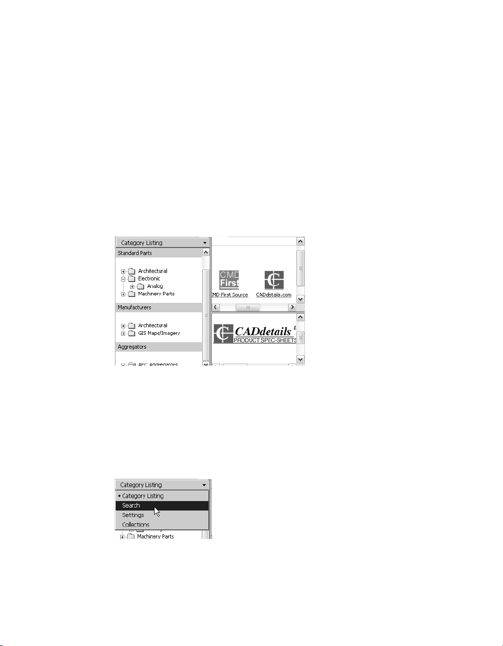
You use the Collections view to select the categories of online content that
you want to display in the Catagory Listing view.
To view online content folders in the Catagory Listing view
■ In DesignCenter Online, at the top of the left pane, click the heading and
then click Category Listing.
The category folders are displayed in the left pane of the window.
Retrieve Content on the Web
You can download content from the Web and use it in your drawings.
Browse for Content
When you use the Category Listing view, you can click the folders in the left
pane to view their contents. These folders may contain other folders.
When you click a folder or an item inside a folder, the contents are displayed
in the Content area. When you click a block, graphical and descriptive information about the block is displayed in the preview area.
Search for Content
When you search for online content with DesignCenter Online, you can
query items with Boolean and multiple-word search strings in the Search
view. You can access Search by clicking the magnifying glass or by choosing
Search from the drop-down heading at the top of the left pane.
58 | Chapter 4 DesignCenter
Page 75

Control the Number of Categories and Items in a Page
By using the Settings view, you can control how many categories or items are
displayed on each page in the content area as a result of a search or folder
navigation.
Collections
You can choose the type of content to navigate and search. In the Collections
pane, you can specify the content types that are displayed each time you
open DesignCenter Online. For example, if you use architectural blocks in
your drawings, you select collections that contain architectural items. Once
you make your selection, categories that you specified are displayed.
Download Content
To download content from the Web, locate the folder containing the content
that you want to use. Then, click a thumbnail image of the content in the
content area. The content is displayed in the preview area along with information about the content. You can drag the block directly from the preview
area into a drawing or tool palette, or you can save it to your computer to be
used later.
To browse for content in DesignCenter Online
1 In DesignCenter Online, at the top of the left pane, click the heading and
then click Category Listing.
2 Click a folder to list its contents. If the folder contains other folders, click
one of them to list its contents.
3 Click an item in the content area to display the item in the Preview area.
To search for content in DesignCenter Online
1 In DesignCenter Online, at the top of the left pane, click the heading and
then click Search.
2 In the Search view, enter a single word or multiple-word strings.
Note The Need Help link provides more information about searches, including
examples of Boolean searches.
Retrieve Content from the Web with DesignCenter Online | 59
Page 76

To specify content collections
1 In DesignCenter Online, at the top of the left pane, click the heading and
then click Collections.
2 In the Collections view, click the check boxes of the collections that you
want to use.
3 Click Update Collections.
The categories that you have selected are displayed in the left pane.
To download content to your computer
1 In DesignCenter Online, at the top of the left pane, click the heading and
then click Category Listing.
2 In the Category folders, click a content item.
3 In the Preview area, under the image of the content item, click Save This
Symbol As.
4 In the Save As dialog box, specify the location on your computer and the
file name.
5 Click Save.
The content is downloaded to your computer.
To download content to your drawing
1 In DesignCenter Online, at the top of the left pane, click the heading and
then click Category Listing.
2 In the Category folders, click a content item to display it in the Preview
area.
3 Drag the image from the Preview area into your drawing or tool palette.
60 | Chapter 4 DesignCenter
Page 77

Customize the Drawing
Environment
You can change many AutoCAD
environment settings in the Options dialog box or
when starting AutoCAD. For example, you can change
how often AutoCAD automatically saves a drawing to a
temporary file, and you can link AutoCAD to folders
containing files you use frequently. Experiment with
different settings until you create the drawing environ-
ment that best fits your needs.
®
window and drawing
In this chapter
■ Set Interface Options
■ Customize Startup
■ Save and Restore Profiles
61
Page 78

Set Interface Options
You can change many of the settings that affect the AutoCAD interface and
drawing environment in the Options dialog box. For example, you can establish how often AutoCAD automatically saves the drawing to a temporary file,
and you can specify the search path for files that you use most often.
Experiment with the settings in the Options dialog box until you find the
best environment for your needs.
Settings in the Options dialog box include the following:
■ Automatic Save (Open and Save tab). Saves your drawing at specified
time intervals. To use this option, in the Options dialog box, Open and
Save tab, select Automatic Save and enter the interval in minutes.
■ Color (Display tab). Specifies the background colors used in the layout
and Model tabs and the color used for prompts and crosshairs.
■ Font (Display tab). Changes the fonts used in the AutoCAD window and
in the text window. This setting does not affect the text in your drawings.
■ Search Path (Files tab). Sets the search path AutoCAD uses to find
support files such as text fonts, drawings, linetypes, and hatch patterns.
To set options
1 From the Tools menu, choose Options.
2 In the Options dialog box, choose the tab you want.
3 Set options as desired.
4 Do either or both of the following:
■ Choose Apply to record the current options settings in the system
registry.
■ Choose OK to record the current options settings in the system registry
and close the Options dialog box.
Command line
OPTIONS
62 | Chapter 5 Customize the Drawing Environment
Page 79

To customize the colors of the application window elements
1 From the Tools menu, choose Options.
2 In the Options dialog box, choose the Display tab ➤ Colors.
3 In the Color Options dialog box, select the element you want to change
by clicking the Model tab or layout tabs images.
As you click areas of the images, the selection is displayed in the Window
Element list. You also can change an attribute by selecting it from the
Window Element list.
4 Select the color you want to use from the Color list.
To specify a custom color, choose Select Color from the Color list.
5 If you want to revert to the colors specified by the Windows Control
Panel, choose Default All.
6 Choose Apply and Close to record the current option settings in the
system registry and close the Color Options dialog box.
7 Choose OK to close the Options dialog box.
Command line
OPTIONS
To change the font displayed in the command line window
1 From the Tools menu, choose Options.
2 In the Options dialog box, choose the Display tab.
3 Under Window Elements, choose Fonts to display the Command Line
Window Font dialog box.
4 Select the appropriate Font, Font Style, and Size.
An example of the current choices appears under Sample Command Line
Font.
5 Choose Apply & Close to record the current option settings and close the
dialog box.
6 Choose OK to close the Options dialog box.
Command line
OPTIONS
Set Interface Options | 63
Page 80

Customize Startup
You can use command line switches to specify several options when
AutoCAD starts. For example, AutoCAD can run a script, start with a specified
template drawing, and display a specified view when a drawing is opened.
With command line switches, you can also set up several AutoCAD icons,
each with different start-up options.
Command line switches are parameters you can add to the acad.exe command line associated with a Windows shortcut icon or the Windows Run
dialog box. You can include several switches within a single command line.
Valid switches are listed in the following table.
/b
/t
/c
/v
/s Support folders Designates support folders other than the
/r Default system pointing
Script name Designates a script to run after AutoCAD starts
Template file name Creates a new drawing based on a template or
Configuration folder Specifies the path for the hardware
View name Designates a particular view of the drawing for
device
(b stands for batch process). Scripts can be
used to set up drawing parameters in a new
drawing file. An SCR file type is assumed.
prototype drawing. A DWT file type is
assumed.
configuration file that you want to use. You
can specify a directory or a particular file. A
CFG file type is assumed. If you don't set the /
c switch, AutoCAD searches the executable
directory and uses the ACADCFGW or
ACADCFG environment variable as a way to
define the configuration file and directory
location.
display at startup of AutoCAD.
current folder. Support files include text fonts,
menus, AutoLISP files, linetypes, and hatch
patterns. The maximum number of folders
you can specify in the path is 15. Each folder
name is delimited by semicolons.
Restores the default system pointing device. It
creates a new configuration file (acad2002.cfg)
and renames the previous acad2002.cfg file to
acad2002.bak.
64 | Chapter 5 Customize the Drawing Environment
Page 81

/nologo No AutoCAD logo screen Starts AutoCAD without first displaying the
logo screen.
/p User-defined registry
profile for starting AutoCAD
Specifies a user-defined registry profile for
starting AutoCAD. The selected profile is in
effect only for the current session of AutoCAD,
unless you make another profile current in the
Options dialog box during that session.
You create or import Profiles on the Profiles
tab in the Options dialog box. With the /p
switch, you can only specify those profiles that
are listed in the Options dialog box. If the
profile does not exist, AutoCAD uses the
current profile.
The syntax for using command line switches is
"drive:pathname\acad.exe" ["drawing name"] [/switch "name"]
When using a switch option, you must follow the switch with a space and
then the name of a file, path, or view within quotation marks. For example
the following entry starts AutoCAD from a folder named AutoCAD 2002 with
the template drawing arch1.dwt, restores a named view
PLAN1, and executes
a script file startup.scr.
"d:\AutoCAD 2002\acad.exe”/t "d:\AutoCAD 2002\template\arch1" /v
"plan1" /b "startup"
AutoCAD resolves the environment settings in the following way:
■ If you use a command line switch to specify an environment setting, the
command line switch overrides the settings specified in either the Options
dialog box or the environment variable.
■ If a command line switch is not set, the corresponding value set in the
Options dialog box is used.
■ If neither a command line switch nor an Options value is set, the environ-
ment variable value is used.
Note Command line switches and environment variables override Options
values for the current session only. They do not alter the system registry.
Customize Startup | 65
Page 82

To start AutoCAD with a command line switch
1 Right-click the AutoCAD icon on the Windows Desktop. Then choose
Properties.
2 In the AutoCAD Properties dialog box, choose the Shortcut tab.
3 In the Target box, edit the parameters for the switch using the following
syntax:
"drive:pathname\acad.exe" ["drawing name"] [/switch "name"]
Valid switches:
/b Script name (b stands for batch process)
/t Template file name
/c Configuration folder
/v View name
/s Support folders
/r Default system pointing device
/nologo No AutoCAD logo screen
/p User-defined registry profile
For example, enter "d:\AutoCAD 2002\acad.exe" /t "d:\AutoCAD
2002\template\arch1" /v "plan1" /b "startup"
4 Choose OK.
Save and Restore Profiles
You can use the Profiles tab in the Options dialog box to create and save your
drawing environment settings as a profile. If you share your workstation with
other users who use the same login name, you can restore your options by
making the profile current. You can also create and save profiles to use with
different projects. By default, AutoCAD stores your current options in a
profile named
name, as well as the current drawing name, in the Options dialog box.
The profile information is stored in the system registry and can be saved to a
text file (an ARG file). AutoCAD organizes essential data and maintains
changes in the registry as necessary.
66 | Chapter 5 Customize the Drawing Environment
UNNAMED PROFILE. AutoCAD displays the current profile
Page 83

Once you save a profile, you can export or import the ARG file to and from
different computers. If you make changes to your current profile during an
AutoCAD session and you want to save those changes in the ARG file, you
must export the profile. When you export the profile with the current profile
name, AutoCAD updates the ARG file with the new settings. You can import
the profile again into AutoCAD to update your profile settings.
For more information about profiles, see
OPTIONS in the Command Reference.
To make a profile current
1 From the Tools menu, choose Options.
2 In the Options dialog box, choose the Profiles tab.
3 On the Profiles tab, select the profile you want to make current.
4 Choose Set Current. Then choose OK.
Command line
OPTIONS
To save a profile
1 From the Tools menu, choose Options.
2 In the Options dialog box, choose the Profiles tab.
3 On the Profiles tab, choose Add to List.
4 In the Add Profiles dialog box, Enter a Profile name and Description.
5 Choose Apply & Close to return to the Options dialog box. Then Choose
OK.
Command line
OPTIONS
To make a profile current before starting AutoCAD
1 On the Windows desktop, right-click the AutoCAD icon to display the
shortcut menu.
2 Choose Properties from the shortcut menu.
3 In the AutoCAD Properties dialog box, choose the Shortcut tab.
4 Under Target, enter /p currentprofile after the current target directory. For
example, to make the profile
User12 current, enter the following in Target:
"c:\AutoCAD 2002\acad.exe"/p user12
5 Choose OK to exit the dialog box.
The profile name you enter is the current profile each time you start
AutoCAD.
Save and Restore Profiles | 67
Page 84

68
Page 85

Pointing Devices
You can control AutoCAD
as a mouse, digitizing puck, or stylus. A pointing device
may have a number of buttons. The first 10 buttons are
automatically assigned by AutoCAD, but you can reas-
sign all but button 1, the pick button, by modifying the
AutoCAD menu file. You can change how mouse
buttons function by choosing the Mouse icon in the
Windows Control Panel.
®
with a pointing device such
In this chapter
■ Pointing Device Buttons
■ Digitizing Tablets
69
Page 86

Pointing Device Buttons
The first 10 buttons are automatically assigned, but you can reassign all but
button 1, the pick button.
On a two-button mouse, the left button is the pick button used to
■ Specify locations
■ Select objects for editing
■ Choose menu options and dialog box buttons and fields
The operation of the right button depends on context; it can be used to
■ End a command in progress
■ Display a shortcut menu
■ Display the Object Snap menu
■ Display the Toolbars dialog box
Right-click operation can be modified in the Options dialog box (
OPTIONS).
The operation of additional buttons on a pointing device is defined in the
AutoCAD menu file.
The Wheel Mouse
The wheel mouse has a small wheel between the buttons. The left and right
buttons behave the same as they do on a standard mouse. You can rotate the
wheel by discrete values. You can use the wheel to zoom and pan in your
drawing without using any AutoCAD commands.
By default, the zoom factor is set to 10 percent; each increment in the wheel
rotation changes the zoom level by 10 percent. The
ZOOMFACTOR system
variable controls the incremental change, whether forward or backward. The
higher the number, the larger the change.
The following table lists the wheel mouse actions supported in AutoCAD.
To... Do this...
Zoom in or out Rotate the wheel forward to zoom in,
Zoom to drawing extents Double-click the wheel button
Pan Hold down the wheel button and drag the
backward to zoom out
mouse
70 | Chapter 6 Pointing Devices
Page 87

To... Do this...
Pan (joystick) Hold down CTRL and the wheel button, and
Display the Object Snap menu With the MBUTTONPAN system variable set
drag the mouse
to 0, click the wheel button
See Also
“Customize Buttons on a Pointing Device” in the Customization Guide
To practice using several features of the mouse
1 Move your mouse and notice that the pointer on the screen changes from
crosshairs while the pointer is in the drawing area, to an arrow when it's
not over the graphics area, and to an I-beam when it's in the text window.
2 As you continue to move the mouse, notice that the numbers in the
coordinate display on the status bar change. These numbers indicate the
exact location, or coordinate, of the crosshairs on the screen. Click in the
coordinate display to turn it off. Notice that the coordinates are updated
only when you click in the graphics area.
3 Find the Snap button on the status bar and click it with the pick button
on your mouse (usually the left button). Notice that the button darkens to
indicate that Snap mode has been turned on.
4 Move the pointer around the screen and observe that it seems to adhere,
or "snap," to points at predetermined and equivalent intervals on the
screen. You can change the size of these intervals.
5 Click the Snap button again to turn Snap mode off.
6 Move the pointer over the Standard toolbar at the top of the graphics area.
As you leave the pointer over a button for a few moments, notice a popup label, called a tooltip, that identifies the button.
7 Move the pointer over double bars at the end of a toolbar. Then, as you
hold down the pick button, drag the toolbar around the screen to
reposition it.
8 Dock the toolbar by dragging it to a docking location at the top, bottom,
or either side of the drawing area. When the outline of the toolbar appears
in the docking area, release the pick button.
Pointing Device Buttons | 71
Page 88

To turn off all shortcut menus in the drawing area
1 From the Tools menu, click Options.
2 In the Options dialog box, click the User Preferences tab.
3 Under Windows Standard Behavior, clear Shortcut Menus in Drawing
Area.
4 Click OK to record the current options settings in the system registry and
close the Options dialog box.
Command line
OPTIONS
To turn off shortcut menus individually
1 From the Tools menu, choose Options.
2 In the Options dialog box, choose the User Preferences tab.
3 Select Shortcut Menus in Drawing Area, and then choose Right-Click
Customization.
4 In the Right-Click Customization dialog box, under Default Mode, Edit
Mode, or Command Mode, select the options to control what happens
when you right-click in the graphics area.
5 Click Apply & Close to close the Right-Click Customization dialog box.
Click OK to record the current options settings in the system registry and
close the Options dialog box.
Command line
OPTIONS
72 | Chapter 6 Pointing Devices
Page 89

Digitizing Tablets
A digitizing tablet, or digitizer, is a peripheral device that can be used to trace
paper drawings into an AutoCAD drawing file or to choose commands from
the digitizing tablet overlay supplied with AutoCAD. With the Wintab driver,
the tablet pointer can also be used instead of a mouse as a system pointer to
choose menu items and drawing objects in AutoCAD or to interact with the
operating system. The tablet pointer can be a puck or a stylus.
The digitizing tablet must first be configured and then can optionally be
calibrated.
■ When the tablet is configured, portions of the tablet surface are designated
as menu areas and a screen-pointing area.
■ When the tablet is calibrated, it can be used to trace geometry from an
existing paper drawing or photograph into an AutoCAD drawing.
You can easily switch between using the tablet uncalibrated as a system
pointer (Tablet mode off) or calibrated for digitizing a drawing (Tablet mode
on). Click the Tablet button on the status bar. If a screen-pointing area has
been designated, a Float button is displayed on the status bar and toggles the
screen-pointing area on and off.
See Also
“Create Tablet Menus” in the Customization Guide
“Set Up a Digitizing Tablet” in the Driver and Peripheral Guide
Digitizing Tablets | 73
Page 90

74
Page 91

Part 2
Start, Organize, and Save a
Drawing
Chapter 7 Start and Save a Drawing 77
Chapter 8 Open an Existing Drawing 87
Chapter 9 Specify Units, Angles, and Scale 101
Chapter 10 Organize Drawings and Apply
Standards 109
75
Page 92

76
Page 93

Start and Save a Drawing
You can start a new drawing several ways. You can use a
wizard to step you through the process, you can start
from scratch using default settings, or you can start
from a template file with a preset environment. In each
case, you can choose the conventions and defaults you
want to use.
In this chapter
■ Start a Drawing from Scratch
■ Use a Setup Wizard
■ Use a Template File to Start a
Drawing
■ Save a Drawing
77
Page 94

Start a Drawing from Scratch
A quick way to begin a new drawing is to start from scratch, which starts a
drawing that uses settings from a default drawing template file.
You can start from scratch from the Create New Drawing dialog box, from the
Select Template dialog box, or without using a dialog box at all. In each case,
you use either the
Use the Create New Drawing Dialog Box
The Create New Drawing dialog box is displayed under the following
conditions:
■ You set the STARTUP system variable to 1 (on).
■ You set the FILEDIA system variable to 1 (on).
■ You click New on the File menu or Qnew on the Standard toolbar when
no drawing template file is specified in the Options dialog box.
The Create New Drawing dialog box provides several methods for starting a
new drawing.
When you use Start from Scratch, you can specify either imperial or metric
units for the new drawing. The setting you select determines default values
used for many system variables controlling text, dimensions, grid, snap, and
the default linetype and hatch pattern file.
■ Imperial. Creates a new drawing based on the imperial measurement
system. The drawing uses internal default values, and the default drawing
boundary, called the drawing limits, is 12 × 9 inches.
■ Metric. Creates a new drawing based on the metric measurement system.
The drawing uses internal default values, and the default drawing boundary is 429 × 297 millimeters.
NEW command or the QNEW command.
Use the Select Template Dialog Box
The Select Template dialog box is displayed under the following conditions:
■ You set the STARTUP system variable to 0 (off).
■ You set the FILEDIA system variable to 1 (on).
■ You click New on the File menu or, by default, Qnew on the Standard
toobar.
At the bottom-right corner of the Select Template dialog box, there is an
Open button with an arrow button next to it. If you click the arrow button,
you can choose between two internal default drawing templates, metric or
imperial.
78 | Chapter 7 Start and Save a Drawing
Page 95

Use a Default Drawing Template File
The fastest way to begin working on a new drawing is to start automatically
with a default drawing template file. No dialog box is displayed with this
method:
■ You set the STARTUP system variable to 0 (off).
■ You set the FILEDIA system variable to 1 (on).
■ You specify a default drawing template file in the Options dialog box on
the Files tab. Click the node labeled “Drawing Template Settings” and
specify a path and drawing template file.
■ You click Qnew on the Standard toolbar.
From now on, a new drawing is immediately created that is based on the
specified default drawing template file.
If no template file is specified in the Options dialog box, QNEW displays the
Select Template dialog box.
To start a drawing from scratch with the Create Drawing dialog box
1 If necessary, set the
STARTUP system variable to 1 and the FILEDIA system
variable to 1. On the command line, enter startup and 1; then enter filedia
and 1.
2 On the File menu, click New.
3 In the Create New Drawing dialog box, click Start from Scratch.
4 Under Default Settings, click either Imperial or Metric.
The new drawing starts as drawing1.dwg. The default drawing name
changes to reflect the number of new drawings that have been started. For
example, if you start another drawing, the default drawing name is
drawing2.dwg.
Command line
NEW
To start a drawing from scratch from a default drawing template file
1 If necessary, set the
STARTUP system variable to 0 and the FILEDIA system
variable to 1. On the command line, enter startup and 0; then enter filedia
and 1.
2 On the Tools menu, click Options. In the Options dialog box, click the
Files tab.
Start a Drawing from Scratch | 79
Page 96

3 In the list of nodes, click the plus next to Drawing Template Settings. Click
the plus next to Drawing Template File Location, and specify a folder path.
Click the plus next to Default Template File Name for
a drawing template file name. Click OK.
4 On the Standard toolbar, click Qnew.
The new drawing starts as drawing1.dwg. The default drawing name
changes to reflect the number of new drawings that have been started. For
example, if you start another drawing, the default drawing name is
drawing2.dwg.
Standard toolbar
Command line
QNEW
Use a Setup Wizard
A setup wizard establishes basic drawing settings step by step. You have two
wizard options to help you set up a drawing:
■ Quick Setup Wizard. Sets units of measurement, precision of displayed
units, and grid limits.
■ Advanced Setup Wizard. Sets units of measurement, precision of
displayed units, and grid limits. Also establishes angle settings such as
units of measurement style, precision, direction, and orientation.
QNEW, and specify
These wizards are available in the Create New Drawing dialog box.
To begin a new drawing using a wizard
1 If necessary, set the STARTUP system variable to 1 and the FILEDIA system
variable to 1.
2 On the File menu, choose New.
3 In the Create New Drawing dialog box, click Use a Wizard.
4 Click Quick Setup or Advanced Setup.
5 Complete the wizard pages using the Next and Back buttons to move
forward and backward.
6 On the last page, click Finish.
Command line
NEW
80 | Chapter 7 Start and Save a Drawing
Page 97

Use a Template File to Start a Drawing
A drawing template file contains standard settings. Select one of the template
files supplied, or create your own template files. Drawing template files have
a .dwt file extension.
When you create a new drawing based on an existing template file and make
changes, the changes in the new drawing do not affect the template file. You
can use one of the template files supplied with AutoCAD, or you can create
your own template files.
Create a Drawing Template File
When you need to create several drawings that use the same conventions and
default settings, you can save time by creating or customizing a template file
instead of specifying the conventions and default settings each time you
start. Conventions and settings commonly stored in template files include
■ Unit type and precision
■ Title blocks, borders, and logos
■ Layer names
■ Snap, Grid, and Ortho settings
■ Drawing (grid) limits
■ Dimension styles
■ Text styles
■ Linetypes
By default, drawing template files are stored in the template folder, where
they are easily accessible.
Recover the Default Drawing Template File
If the settings in the AutoCAD
®
drawing template files acad.dwt or acad-
iso.dwt have been changed from the original defaults, you can reset them by
starting a new drawing with no template and then saving the drawing as a
drawing template file, replacing acad.dwt or acadiso.dwt.
You can start a new drawing with the original defaults by using
NEW to dis-
play the Select Template dialog box. To do this, click the arrow next to the
Open button and then click one of the “no template” options from the list.
Use a Template File to Start a Drawing | 81
Page 98

To start a drawing by selecting a template file
1 On the File menu, click New.
2 In the Select Template dialog box, scroll through the list of templates and
select a template from the list and click Open.
AutoCAD opens the drawing as drawing1.dwg. The default drawing name
changes to reflect the number of new drawings that have been opened.
For example, if you open another drawing from a template, the default
drawing name is drawing2.dwg.
If you want to start a new drawing with no template file, click the arrow
next to the Open button and then click one of the “no template” options
from the list.
Command line
NEW
To create a drawing template file from an existing drawing
1 On the File menu, click Open.
2 In the Select File dialog box, select the file you want to use as a template
and click OK.
3 If you want to delete the existing file contents, from the Modify menu,
choose Erase.
4 At the Select Objects prompt, enter all, and then select the border and title
block (if you want to remove them) and enter r (Remove).
5 On the File menu, click Save As.
6 In the Save Drawing As dialog box under Files of Type, select the Drawing
Template file type.
®
DWT files must be saved in AutoCAD LT
2004 format. To create a DWT
file in AutoCAD 2000 format, save the file in the AutoCAD 2000 DWG
format and then rename the DWG file using a DWT extension.
7 In the File Name box, enter a name for the template. Click Save.
8 Enter a description of the template and click OK.
The new template is saved in the template folder.
Standard toolbar
Command line
OPEN
To recover the default drawing template files
1 On the File menu, click New.
82 | Chapter 7 Start and Save a Drawing
Page 99

2 In the Select Template dialog box, click the arrow next to the Open button
and then click one of the options from the list:
■ Open with no Template - Imperial to restore acad.dwt
■ Open with no Template - Metric to restore acadiso.dwt
The drawing opens with the default settings.
3 On the File menu, click Save As.
4 In the Save Drawing As dialog box, select the Drawing Template file type.
Save the drawing with its original name, either acad.dwt for imperial or
acadiso.dwt for metric.
5 Click Save.
Command line
Save a Drawing
You save drawing files for later use just as you do with other Windows applications. AutoCAD also provides automatic saving, backup files, and other
options for saving.
When you are working on a drawing, you should save it frequently. Saving
protects you from losing work in the event of a power failure or other unexpected event. If you want to create a new version of a drawing without
affecting the original drawing, you can save it under another name.
The file extension for AutoCAD drawing files is .dwg, and unless you change
the default file format in which drawings are saved, drawings are saved in the
AutoCAD LT 2004 drawing-file format. This format is optimized for file compression and for use on a network.
Save Your Drawing Automatically
If you turn on the automatic saving option, AutoCAD saves your drawing at
specified time intervals. By default, files saved automatically are temporarily
assigned the name filename_a_b_nnnn.sv$. The file name is the current
drawing name, a is the number of open instances of the same drawing file in
the same AutoCAD session, b is the number of open instances of the same
drawing in different sessions of AutoCAD, and nnnn is a random number
generated by AutoCAD.
NEW
Files that are automatically saved are deleted when AutoCAD closes a
drawing in the normal way. Saved files remain in the event of a crash or
power failure. To recover a previous version of your drawing from the automatically saved file, rename the file using a .dwg extension.
Save a Drawing | 83
Page 100

Use Backup Files
If you turn on automatic backups, AutoCAD saves the previous version of
your drawing files to a file with the same name and a .bak file extension. To
recover the previous version of your drawing from a backup file, rename the
file using a .dwg extension.
Save Part of a Drawing File
If you want to create a new drawing file from part of an existing drawing, you
can use
BLOCK or WBLOCK. With either command, you can select objects or
specify a block definition in your current drawing and save them in a new
drawing file. You can also save a description along with the new drawing.
Save to a Different Type of Drawing File
You can save a drawing to an earlier version of the DWG or DXF format or
save a drawing as a template file. Choose the format from Files of Type in the
Save Drawing As dialog box.
Reduce the Time Required to Save a Drawing File
You can reduce the time required to save a drawing file if you specify incremental saves rather than full saves. An incremental save updates only those
portions of the saved drawing file that you changed.
When you use incremental saves, drawing files will contain a percentage of
potentially wasted space. This percentage increases after each incremental
save until it reaches a specified maximum, at which time a full save is performed instead. You can set the incremental save percentage in the Open and
Save tab of the Options dialog box or by setting the value of the system vari-
ISAVEPERCENT. If you set the value of ISAVEPERCENT to 0, all saves are full
able
saves.
To reduce the size of drawing files, it is recommended that you perform a full
save (with
IPERCENTSAVE set to 0) before transmitting or archiving a drawing.
See Also
“Save Drawings to Previous Drawing File Formats” on page 722
“Export Drawings to Other File Formats” on page 716
“Create Drawing Files for Use as Blocks” on page 321
“Add Identifying Information to Drawings” on page 95
To save a drawing
1 On the File menu, click Save.
If you previously saved and named the drawing, AutoCAD saves any subsequent changes and redisplays the Command prompt. If you have never
saved the drawing, the Save Drawing As dialog box is displayed.
84 | Chapter 7 Start and Save a Drawing
 Loading...