

Air series
user manual
LIUAIR1AU3-01
A0LI BR00 D0166

ure
hitect
rc
a
e
A
af
S
s
F
ex
l
f

INDICE
1 Descrizione radiocomando serie AIR ......................................................................................... 2
1.1 Funzionamento del radiocomando .......................................................................................... 2
1.2 Applicazioni ............................................................................................................................. 2
1.3 Dati tecnici .............................................................................................................................. 3
1.4 Funzione di sicurezza: protezione dell’arresto ........................................................................ 4
1.5 Protezione dai movimenti non voluti dalla posizione di riposo ................................................ 4
1.6 Identificazione del radiocomando ........................................................................................... 4
2 Conformità e frequenze ............................................................................................................... 4
2.1 Banda di frequenze 433.050-434.790 MHz ............................................................................ 4
2.2 Banda di frequenze 915-928 MHz .......................................................................................... 5
3 Valutazione dei rischi ................................................................................................................... 6
3.1 Valutazione dei rischi per macchine radiocomandate ............................................................. 6
3.2 Formazione del personale ...................................................................................................... 7
3.3 Condizioni lavorative ............................................................................................................... 7
4 Unità trasmittente A8 ................................................................................................................... 8
4.1 Descrizione unità A8 ............................................................................................................... 8
4.2 Funzionamento ....................................................................................................................... 8
4.3 Avvertenze per l’utilizzo ........................................................................................................ 10
4.4 Carica dell’unità A8 ............................................................................................................... 12
4.5 Docking station AIRDOCK01 ................................................................................................ 12
5 Unità ricevente ............................................................................................................................ 13
5.1 Descrizione unità ricevente G ............................................................................................... 13
5.2 Descrizione unità ricevente L ................................................................................................ 14
5.3 Funzionamento ..................................................................................................................... 14
5.4 Avvertenze per l’installazione ............................................................................................... 15
6 Batteria AIRBM3V7L ................................................................................................................... 17
6.1 Dati tecnici ............................................................................................................................ 18
6.2 Avvertenze per l’uso ............................................................................................................. 18
6.3 Rottamazione ........................................................................................................................ 19
7 Docking station ........................................................................................................................... 19
7.1 Collegamento tra docking station e alimentatore .................................................................. 20
8 Manutenzione del radiocomando .............................................................................................. 21
8.1 Manutenzione ordinaria ........................................................................................................ 21
8.2 Manutenzione straordinaria .................................................................................................. 23
8.3 Malfunzionamenti .................................................................................................................. 23
9 Manutenzione della macchina ................................................................................................... 25
10 Rottamazione .............................................................................................................................. 25
1
LIUAIR1AI3-01.fm AUTEC - Serie AIR
2 Descrizione radiocomando serie AIR
LEGENDA
Questo simbolo indica un’avvertenza importante la cui non osservanza porta a una situazione di pericolo per le persone e le cose.
Questo simbolo indica un documento reperibile nella parte dedicata del sito
@
internet di Autec.
Ricordarsi che tutta la documentazione deve essere conservata per tutta la vita del
radiocomando: dopo averla letta tenerla a disposizione per future consultazioni.
Contattare Autec qualora alcune istruzioni e/o avvertenze del presente documento
non risultassero chiare. Per nessun motivo possono essere riprodotte, in qualsiasi
forma/mezzo parti del presente documento senza permesso scritto di Autec (inclusa registrazione e fotocopia).
Funzionamento del radiocomando
1 Descrizione radiocomando serie AIR
1.1 Funzionamento del radiocomando
Un radiocomando industriale è utilizzato per comandare macchine da posizione remota senza una connessione fisica (es. fili o cavi di collegamento) tra l’operatore e la macchina. Esso
è costituito da un’unità trasmittente portatile da cui l’operatore comanda la macchina e da
un’unità ricevente installata a bordo della macchina stessa.
Le due unità comunicano tra loro in modo continuo tramite un collegamento radioelettrico.
La ricerca di una frequenza libera a cui operare avviene automaticamente.
Le due unità codificano i messaggi tramite un indirizzo unico (prodotto da Autec una sola volta) e univoco (specifico per ogni radiocomando).
1.2 Applicazioni
Un radiocomando della serie AIR può essere installato su macchine per sollevamento e movimentazione di materiale in genere (es. carroponte).
Come richiesto dalle norme ISO 12100 e ISO 14121, è necessario effettuare per ogni macchina una valutazione dei rischi (vedere capitolo 3). Solo l’esito positivo di questa valutazione
può consentire l’utilizzo del radiocomando. In ogni caso, questo radiocomando non deve essere installato:
- su macchine per ambienti che necessitano di apparecchiature con caratteristiche antideflagranti
- su macchine per la movimentazione, il sollevamento e il trasporto di persone
- su macchine che potrebbero causare situazioni pericolose in caso di arresto dovuto alla
perdita del collegamento radioelettrico
AUTEC - Serie AIR
Descrizione radiocomando serie AIR 3
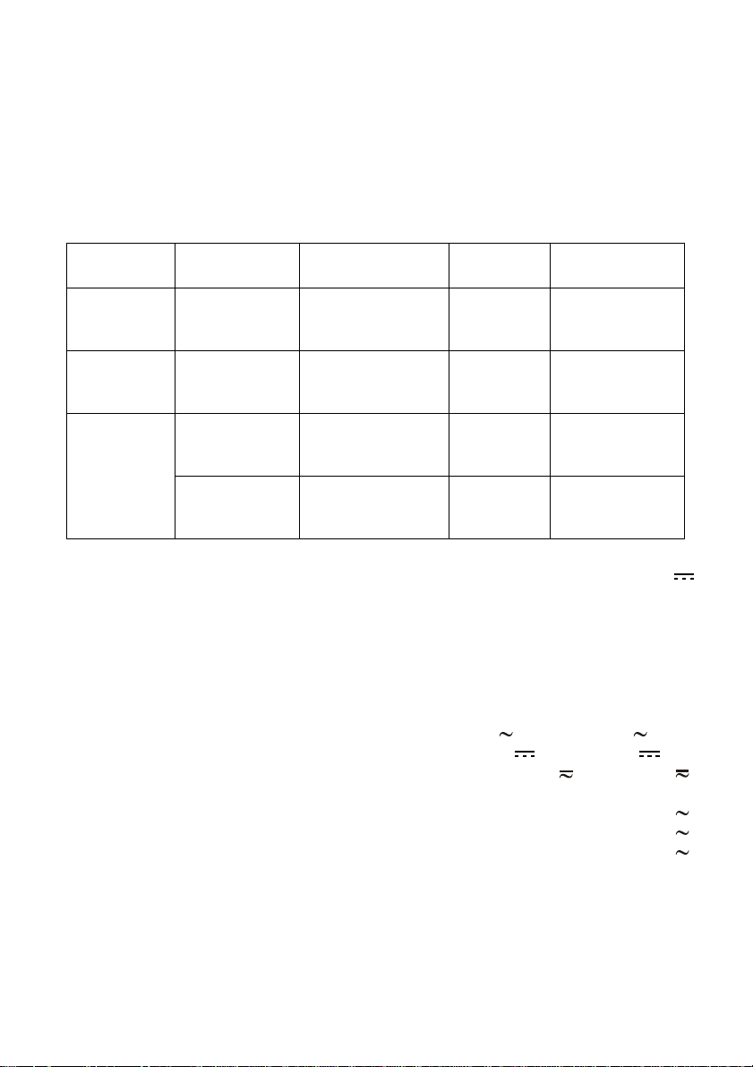
Dati tecnici
1.3 Dati tecnici
Tempo di risposta dei comandi (tipico) ..................................................................... 100 ms
Raggio d’azione (tipico) ....................................................................................... 75 - 100 m
Tempo di arresto (tipico) .......................................................................................... 100 ms
Tempo di arresto massimo ........................................................................................... 0.5 s
Performance Level della funzione di sicurezza secondo la EN ISO 13849-1:
Protezione dell’arresto ......................................................................................... cat.3 PL d
Trasporto Radiocomando
Stoccaggio Radiocomando
Unità trasmittente
Utilizzo
Unità ricevente
Temperatura
Classe 2K4
da -40°C a +70°C
(da -40°F a +158°F)
Classe 1K5
da -40°C a +70°C
(da -40°F a +158°F)
Classe 4K4H
da -20°C a +55°C
(da -4°F a +130°F)
Classe 4K4H
da -20°C a +70°C
(da -4°F a +158°F)
Umidità
relativa
Classe 2K4
95%
Classe 1K3
da 5% a 95%
Classe 4K4H
da 4% a 100%
Classe 4K4H
da 4% a 100%
Pressione
dell’aria
Classe 2K4
da 70 kPa a
106 kPa
Classe 1K5
da 70 kPa a
106 kPa
Classe 4K4H
da 70 kPa a
106 kPa
Classe 4K4H
da 70 kPa a
106 kPa
Unità trasmittente A8
Alimentazione (batteria AIRBM3V7L) ............................................................ Li-ion 3.7 V
Antenna ..................................................................................................................... interna
Materiale involucro ......................................................................................... PA 6 (20% fg)
Grado di protezione ...................................................................................... IP65 (NEMA 4)
Dimensioni .................................................... 64.5 x 179 x 37.5 mm (2.54 x 7.05 x 1.48 In)
Peso...............................................................................................................250 g (0.55 Lb)
Autonomia (a 20°C / 68°F)..............................................................................................40 h
Unità ricevente
Tensione di alimentazione ...................................... 45 - 240 V (max 40 - 264 V 0.4 A)
opzionale per unità ricevente G ............................ 12 - 24 V (max 9 - 30 V 1 A)
Tensione degli ingressi digitali (per unità ricevente G) .............10 - 60 V
(max 9 - 66 V )
Antenna ..................................................................................................................... interna
Portata dei contatti di STOP............................................................................ 4 A (250 V )
Portata dei contatti di SAFETY ....................................................................... 4 A (250 V )
Portata dei contatti di comando....................................................................... 6 A (250 V )
Materiale involucro ......................................................................................... PA 6 (20% fg)
Grado di protezione ...................................................................................... IP65 (NEMA 4)
Dimensioni ........................................................ 123 x 202 x 83 mm (4.84 x 7.95 x 3.23 In)
Peso .............................................................................................................. 1.2 kg (2.7 Lb)
LIUAIR1AI3-01.fm
AUTEC - Serie AIR

4 Conformità e frequenze
Funzione di sicurezza: protezione dell’arresto
1.4 Funzione di sicurezza: protezione dell’arresto
La funzione di arresto porta la macchina in uno stato sicuro ogni volta che è necessario fermarla a causa di una situazione potenzialmente pericolosa. A seconda dei casi, questa funzione viene attivata volontariamente dall’operatore tramite il pulsante STOP o può intervenire
automaticamente quando il collegamento radioelettrico risulta errato o interrotto (l’unità ricevente decide autonomamente di arrestare il radiocomando).
1.5 Protezione dai movimenti non voluti dalla posizione di riposo
Questa funzione di sicurezza protegge il sistema “macchina+radiocomando” dai movimenti
non voluti, intesi come i movimenti della macchina non attivati dall’operatore in modo volontario, ma causati da eventuali guasti elettrici e meccanici del radiocomando.
Questa protezione controlla la posizione neutra (di riposo) dei tasti che comandano i movimenti nella macchina. Ogni volta che viene azionato uno di questi tasti, l’unità trasmittente
invia sia il comando di movimento che il comando SAFETY.
1.6 Identificazione del radiocomando
Come richiesto dalla norma IEC 60204-32, ogni radiocomando è identificato in modo univoco
tramite un numero di matricola (SERIAL N.).
Il SERIAL N. si trova nella targhetta d’identificazione delle due unità.
2 Conformità e frequenze
I radiocomandi della serie AIR possono lavorare in due bande di frequenze distinte:
- 433.050 - 434.790 MHz
- 915.000 - 928.000 MHz.
La frequenza a cui un radiocomando può operare è imposta da leggi e normative in funzione del mercato di utilizzo. Affinché il sistema “macchina+radiocomando” risulti conforme e possa quindi essere utilizzato, queste leggi e
normative devono essere rispettate: in caso contrario, il sistema rischierebbe
di essere messo sotto sequestro da parte degli organismi competenti.
Autec non potrà assumersi alcuna responsabilità se il radiocomando viene impostato con frequenza non permessa.
2.1 Banda di frequenze 433.050-434.790 MHz
2.1.1 Conformità
Ogni radiocomando della serie AIR che opera nella banda di frequenza 433.050-
434.790 MHz è conforme alla Direttiva 1999/5/CE (R&TTE) e ai suoi requisiti essenziali.
Ogni radiocomando è inoltre conforme alle norme armonizzate riportate nella dichiarazione
di conformità CE.
@
La dichiarazione di conformità CE è reperibile nella sezione relativa dell’area “Servizio post-vendita” all’interno del sito internet di Autec.
AUTEC - Serie AIR

Conformità e frequenze 5
Banda di frequenze 915-928 MHz
2.1.2 Frequenze
Il collegamento radioelettrico tra le unità dei radiocomandi Autec della serie AIR avviene ad
una delle frequenze ammesse dalle normative europee in vigore al momento dell’immissione
nel mercato.
Frequenze utilizzate nella banda di frequenza 433.050-434.790 MHz ............................. 64
Potenza RF ............................................................................................................... <1 mW
Canalizzazione utilizzata ........................................................................................... 25 kHz
2.1.3 Mercato
I radiocomandi della serie Air che operano nella banda di frequenza 433.050-434.790 MHz
possono essere utilizzati all’interno della UE (Unione Europea) e della EFTA (European Free
Trade Association).
2.2 Banda di frequenze 915-928 MHz
2.2.1 Conformità
Ogni radiocomando della serie AIR che opera nella banda di frequenza 915-928 MHz è conforme ai requisiti essenziali:
- FCC (Federal Communication Commission) Part 15
- IC (Industry Canada) RSS-102
Unit FCC ID IC number
A8 OQA-A08LA0AM 9061A-A08LA0AM
Unità ricevente G OQA-RGAAA00M 9061A-RGAAA00M
Unità ricevente L OQA-RLBCA00M 9061A-RLBCA00M
Operation is subject to the following two conditions:
(1) this device may not cause harmful interference, and
(2) this device must accept any interference received, including interference that may cause
undesired operation.
Changes or modifications not expressly approved by the party responsible for compliance
could void the user’s authority to operate the equipment.
2.2.2 Frequenze
Il collegamento radioelettrico tra le unità dei radiocomandi Autec della serie AIR avviene ad
una delle frequenze ammesse dalle normative US e canadesi in vigore al momento dell’immissione nel mercato.
Frequenze utilizzate nella banda di frequenza 915-928 MHz ......................................... 256
Potenza RF .................................................................... in accordo con i requisiti FCC e IC
Canalizzazione utilizzata ........................................................................................... 50 kHz
2.2.3 Mercato
I radiocomandi della serie Air che operano nella banda di frequenza 915-928 MHz possono
essere utilizzati all’interno del mercato statunitense e canadese.
LIUAIR1AI3-01.fm
AUTEC - Serie AIR

6 Valutazione dei rischi
Valutazione dei rischi per macchine radiocomandate
3 Valutazione dei rischi
Occorre valutare sempre se la macchina può essere radiocomandata o meno. Infatti, come
richiesto dalle normative tecniche del mercato in cui il sistema “macchina+radiocomando”
viene impiegato, è necessario effettuare per ogni macchina una valutazione dei rischi con la
relativa analisi.
Solo l’esito positivo di questa valutazione può consentire l’installazione e l’utilizzo del radiocomando.
La responsabilità di questa valutazione dei rischi è del costruttore della macchina stessa e/o di chi decide l’installazione e l’utilizzo del radiocomando.
Autec non potrà assumersi alcuna responsabilità se questa valutazione non è stata effettuata in maniera corretta o è stata fatta parzialmente.
Se la valutazione dei rischi lo richiede, è necessario predisporre misure di protezione che
prevengano, riducano e segnalino le situazioni di potenziale pericolo.
3.1 Valutazione dei rischi per macchine radiocomandate
Nell’effettuare la valutazione dei rischi della macchina o del sistema in cui è installato il radiocomando, deve essere considerato che:
- alcune macchine non possono essere radiocomandate: verificare le applicazioni non consentite (vedere paragrafo 1.2)
- a causa di disturbi o interferenze persistenti può interrompersi il collegamento radioelettrico tra le due unità
- devono essere prese in considerazione tutte le avvertenze relative all’installazione, all’uso
e alla manutenzione fornite da Autec.
3.1.1 Aspetti da considerare legati al collegamento radioelettrico
In tutti i casi in cui il collegamento radioelettrico si interrompe (es. arresto, batteria scarica,
spegnimento automatico, mancanza alimentazione unità ricevente):
- tutte le uscite dell’unità ricevente vengono disattivate: se questo funzionamento causa una
situazione pericolosa, è necessario che i relativi comandi nella macchina siano mantenuti
attivi
- non è più possibile attivare o disattivare i comandi della macchina fino al successivo avviamento del radiocomando.
3.1.2 Ritardo del tempo di risposta dei comandi
Per le caratteristiche del mezzo radio (es. presenza interferenze, raggiunto raggio d’azione),
il ritardo tra il rilascio di un comando nell'unità trasmittente e la disattivazione della relativa
uscita nell'unità ricevente può prolungarsi fino al “Tempo di arresto massimo”.
Chi decide l'installazione del radiocomando deve assicurarsi che questo ritardo non possa
mai portare a una situazione di pericolo nella specifica applicazione.
AUTEC - Serie AIR

Valutazione dei rischi 7
Formazione del personale
3.1.3 Protezione dalle attivazioni involontarie
L’involucro dell’unità trasmittente è realizzato in modo da proteggere gli attuatori da attivazioni involontarie, soddisfando le necessità lavorative, le richieste ergonomiche e i vincoli
normativi.
Si devono valutare ed eventualmente adottare misure di protezione aggiuntive per gli attuatori (es. comandi con consenso a due mani, funzionalità “dead-man”) nel caso in cui particolari ambienti, equipaggiamenti e modalità di lavoro possano causare urti accidentali agli
stessi.
3.2 Formazione del personale
Tutte le operazioni di installazione, uso e manutenzione devono obbligatoriamente essere
effettuate da personale qualificato e adeguatamente addestrato in relazione:
- alle avvertenze derivanti dalla valutazione dei rischi
- alle normative e alle leggi di riferimento
- alle avvertenze e alle istruzioni presenti nella documentazione del radiocomando industriale e della macchina dotata di radiocomando
- alle indicazioni di colui che installa il radiocomando sulla macchina e del responsabile alla
sicurezza del luogo di lavoro dove il sistema macchina+radiocomando viene impiegato
3.3 Condizioni lavorative
Per garantire il corretto utilizzo del radiocomando devono essere sempre rispettate tutte le
prescrizioni vigenti sulla sicurezza del lavoro e sulla prevenzione degli infortuni sul lavoro.
Inoltre, si devono sempre osservare tutte le leggi nazionali relative all’uso sia della macchina
che del radiocomando vigenti nel singolo stato dove il sistema è utilizzato.
Autec non potrà assumersi alcuna responsabilità se il radiocomando è utilizzato in
condizioni lavorative non a norma.
LIUAIR1AI3-01.fm
AUTEC - Serie AIR
8 Unità trasmittente A8
Descrizione unità A8
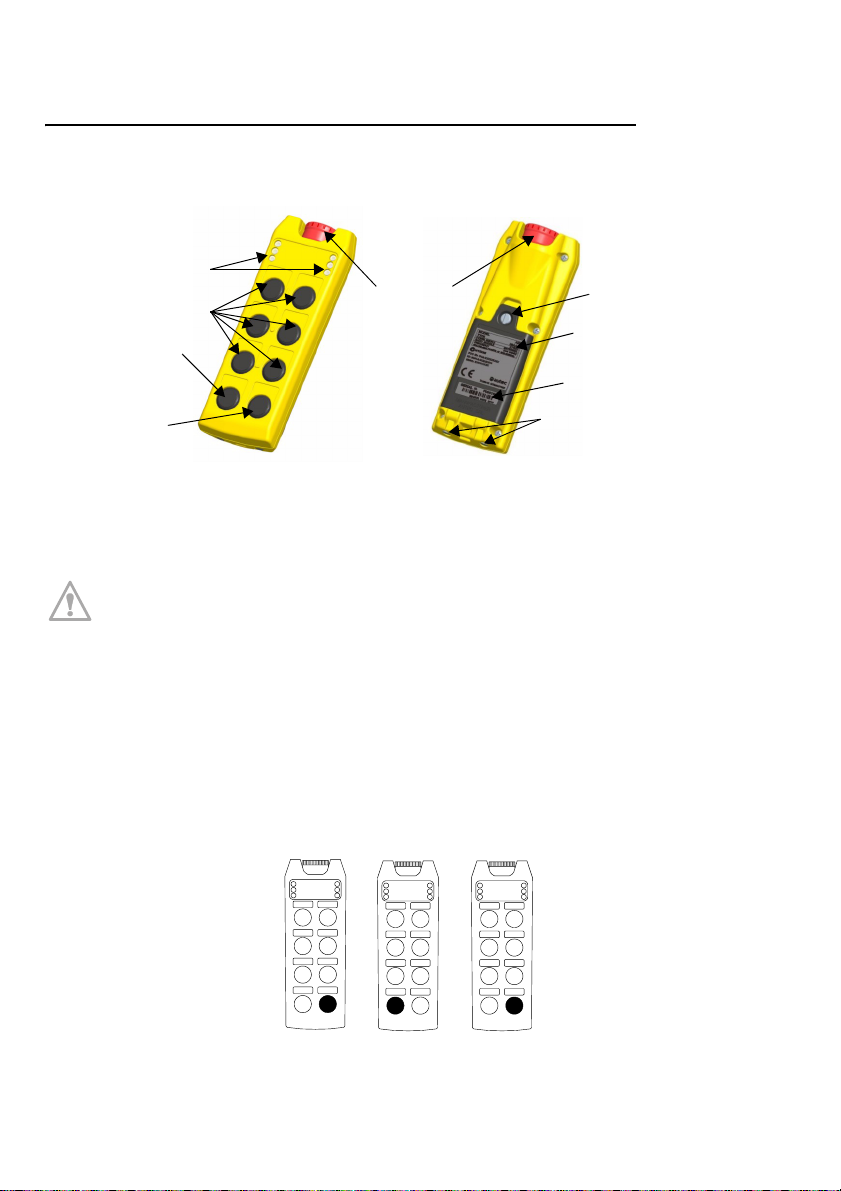
4 Unità trasmittente A8
4.1 Descrizione unità A8
LED
Pulsante STOP
Tasti comandi
Tasto FUNCTION
Vite e coperchio batteria
Targhetta dati tecnici
Targhetta di identificazione
Tasto START
Contatti per la carica
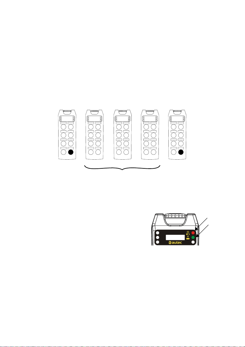
4.2 Funzionamento
4.2.1 Avviamento con codice PIN
Come richiesto dalla norma IEC 60204-32, l’avviamento del radiocomando è
protetto da un codice PIN al fine di impedire un uso non autorizzato della macchina.
Durante l’avviamento premere ogni tasto entro 3 secondi dal rilascio del precedente altrimenti l’unità trasmittente si spegne.
Avviamento con PIN di fabbrica
Con unità ricevente alimentata, eseguire la seguente procedura:
1) premere il tasto START fino all’accensione del LED verde
2) premere il tasto FUNCTION
3) premere il tasto START fino a quando il LED verde lampeggia lentamente.
STOP
1
R
2
G
34
S1 S2
STARTFUNCT.
STOP
R
1
G
2
34
S1 S2
STARTFUNCT.
STOP
R
1
G
2
34
S1 S2
STARTFUNCT.
AUTEC - Serie AIR
1) START 2) FUNCTION 3) START
Unità trasmittente A8 9
Funzionamento
Avviamento con PIN personalizzato
Se richiesto dalla valutazione dei rischi, il PIN può essere modificato al fine di impedire un
uso non autorizzato.
La procedura per personalizzare il PIN è riportata nel documento “Menu of Transmit-
@
ting Unit (MTU)” reperibile nella parte dedicata del sito internet di Autec.
Con unità ricevente alimentata, eseguire la seguente procedura:
1) premere il tasto START fino all’accensione del LED verde
2) premere la sequenza PIN 1, PIN 2 e PIN 3 relativi al codice PIN riportato in scheda tecni-
ca (se il PIN 1 e/o il PIN 3 è il tasto START non deve essere considerato nella sequenza
del codice)
3) premere il tasto START fino a quando il LED verde lampeggia lentamente.
STOP
1
R
2
G
34
S1 S2
STARTFUNCT.
STOP
1
R
2
G
34
S1 S2
STARTFUNCT.
STOP
1
R
2
G
34
S1 S2
STARTFUNCT.
STOP
1
R
2
G
34
S1 S2
STARTFUNCT.
STOP
1
R
2
G
34
S1 S2
STARTFUNCT.
PIN 1 PIN 2 PIN 3
1) START 3) START
2) PIN
4.2.2 Attivazione comandi
Premere i tasti relativi ai comandi che si intendono effettuare.
4.2.3 Segnalazioni luminose durante il funzionamento
LED verde
- acceso fisso: l’unità trasmittente e ricevente non comunicano tra loro
- lampeggia velocemente: è possibile avviare il radiocomando premendo il tasto START
- lampeggia lentamente (un lampeggio al secondo): è
possibile inviare comandi
STOP
PD5580-00
LED rosso
LED verde
LED rosso
- acceso fisso all’accensione: il pulsante STOP è attivo o guasto
- lampeggia 2 volte al secondo all’accensione: almeno uno dei comandi è attivo o guasto
- lampeggia 3 volte al secondo all’accensione: l’unità è scarica
- acceso per 2 s: l’unità non funziona correttamente
- lampeggia lentamente: l’autonomia è di circa 4 h
- lampeggia velocemente: rimangono 10 min di autonomia
Le segnalazioni degli altri quattro LED dipendono dalla funzione associata al tasto FUNCTION (o dagli ingressi digitali se cablati nella ricevente G).
LIUAIR1AI3-01.fm
AUTEC - Serie AIR

10 Unità trasmittente A8
Avvertenze per l’utilizzo
4.2.4 Tasto FUNCTION
Al tasto FUNCTION possono essere associate differenti funzioni dei relè nel ricevitore (vedere scheda tecnica).
4.2.5 STOP
Il pulsante STOP va premuto solo quando c’è la necessità di arrestare immediatamente la
macchina per il verificarsi di una qualunque situazione di pericolo.
La pressione del pulsante STOP, oltre ad arrestare la macchina, spegne l’unità trasmittente.
Per riprendere a lavorare dopo la pressione del pulsante STOP, è necessario:
- verificare che le condizioni operative e di utilizzo siano sicure
- disinserire il pulsante STOP tirandolo o ruotandolo nel verso indicato
- avviare il radiocomando.
Secondo la EN ISO 13849-1, il valore B
per il pulsante STOP è pari a 6050.
10d
4.2.6 Spegnimento
Lo spegnimento dell’unità A8 avviene:
- volontariamente quando vengono premuti a fondo il tasto START e subito dopo il tasto
FUNCTION fino all’accensione del LED rosso.
- in conseguenza della pressione del pulsante STOP
- automaticamente quando trascorre un tempo prefissato in cui l’unità rimane avviata senza
comandi di movimento inseriti. Questo tempo è riportato in scheda tecnica (SWITCHOFF).
Prima che l’unità A8 si spenga automaticamente, i LED verde e rosso lampeggiano alternativamente per 30 secondi.
4.3 Avvertenze per l’utilizzo
Oltre a tutte le indicazioni imposte dal costruttore della macchina, dall’installatore del radiocomando e dal responsabile della sicurezza dell’area di lavoro, un operatore dovrà sempre
rispettare le seguenti avvertenze.
Prima di iniziare a lavorare, l’operatore deve:
- collocarsi in una posizione che consenta il controllo diretto della macchina
radiocomandata e dei movimenti del carico, nonché in una posizione che garantisca le sue condizioni di sicurezza rispetto alle altre operazioni e/o attività
e/o lavorazioni che si svolgono nel luogo di lavoro
- non avviare o utilizzare mai l’unità trasmittente in situazioni lavorative in cui
si possa perdere l’equilibrio o si possa inciampare
- verificare sempre il corretto funzionamento meccanico del pulsante STOP.
Se risultasse impossibile o difficile azionare tale pulsante, non utilizzare il radiocomando
- non avviare mai l’unità trasmittente se non per iniziare a lavorare: l’uso improprio potrebbe causare situazioni di pericolo
AUTEC - Serie AIR

Unità trasmittente A8 11
Avvertenze per l’utilizzo
- non avviare o azionare mai l’unità trasmittente in posti chiusi, fuori visibilità
o fuori dal raggio d’azione del radiocomando: anche in questi casi è infatti
possibile creare un collegamento radioelettrico con il rischio di far eseguire
dei comandi non voluti alla macchina radiocomandata
- apprendere la corrispondenza tra i tasti e le manovre della macchina indicata
nella scheda tecnica allegata e la simbologia presente nel pannello
dell’unità A8 (la simbologia utilizzata è decisa dal costruttore della macchina
e/o installatore in base all’operatività e alle funzionalità della stessa).
Durante il normale funzionamento, l’operatore deve:
- seguire mediante controllo visivo diretto tutti i movimenti della macchina e
del carico rimanendo all’interno del raggio d’azione del radiocomando
- utilizzare l’unità trasmittente in modo agevole e comodo evitando che possa
cadere accidentalmente. Il fodero fornito con il radiocomando serve a tale
scopo
- prestare attenzione agli avvisi e alle segnalazioni visive e acustiche e adottare tutte le precauzioni e le azioni necessarie a evitare che il movimento della
macchina radiocomandata possa creare situazioni di pericolo per le persone
e/o le cose
- prestare attenzione a tutta l’area di lavoro e intervenire immediatamente premendo il pulsante STOP quando si verifica una situazione di pericolo
- prestare attenzione alle segnalazioni di batteria scarica. L’unità A8 non è utilizzabile durante la carica, perciò è necessario terminare le operazioni pericolose (es. carico sospeso) prima che si scarichi completamente
- in caso di malfunzionamento, mettere fuori servizio il sistema “macchina+radiocomando” fino alla completa eliminazione del problema
Dopo avere utilizzato il radiocomando, l’operatore deve:
- spegnere l’unità trasmittente quando si sospende o si interrompe momentaneamente il lavoro, evitando di lasciare il carico sospeso (anche durante la
carica dell’unità).
- non lasciare mai l’unità trasmittente incustodita se è accesa.
LIUAIR1AI3-01.fm
AUTEC - Serie AIR
12 Unità trasmittente A8
Carica dell’unità A8
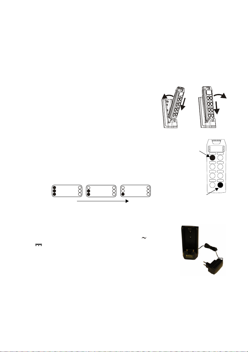
4.4 Carica dell’unità A8
All’interno dell’unità A8 è presente una batteria ricaricabile (AIRBM3V7L) che viene fornita
parzialmente caricata.
Per utilizzare correttamente l’unità A8 e la sua batteria è necessario conoscere e tenere in
considerazione quanto indicato nel capitolo relativo.
Dopo aver alimentato la docking station con l’apposito alimentatore:
1) inserire l’unità A8 nella docking station: inizia la carica indicata dal LED rosso acceso fisso (durata massima 4 h)
1b
2) estrarre l’unità A8 dalla docking station quando necessario
Nota: quando il LED verde si accende l’unità A8 è completamente carica.
Eseguire la carica dell’unità ad una temperatura compresa tra
5°C e 45°C.
Indicazione dell’autonomia dell’unità A8
Per verificare l’autonomia dell’unità trasmittente, eseguire la seguente procedura:
1) spegnere l’unità trasmittente e disinserire il pulsante di STOP
2) tenere premuti i tasti S1 e START fino a quando i 3 LED di sinistra si accendono indicando l’autonomia dell’unità (3 LED accesi massima autonomia).
Dopo alcuni secondi, l’indicazione dell’autonomia sparisce.
1
2
3
R
1
G
2
4
34
MAX MIN
1
R
2
G
3
R
G
4
1a
S1
START
2b
2a
STOP
1
R
2
G
34
S1 S2
STARTFUNCT.
4.5 Docking station AIRDOCK01
La docking station AIRDOCK01 serve per caricare l’unità A8.
Collegare lo spinotto dell’alimentatore alla presa posta sul retro della
docking station. L’alimentatore funziona a 100 - 240 V (opzionale
10 - 30 V ).
Per utilizzare correttamente la docking station con l’apposito alimentatore è necessario rispettare le indicazioni riportate nel capitolo relativo.
AUTEC - Serie AIR
Unità ricevente 13
Descrizione unità ricevente G
5 Unità ricevente
Targhetta dati tecnici
Targhetta identificazione
LED ENABLE
LED POWER
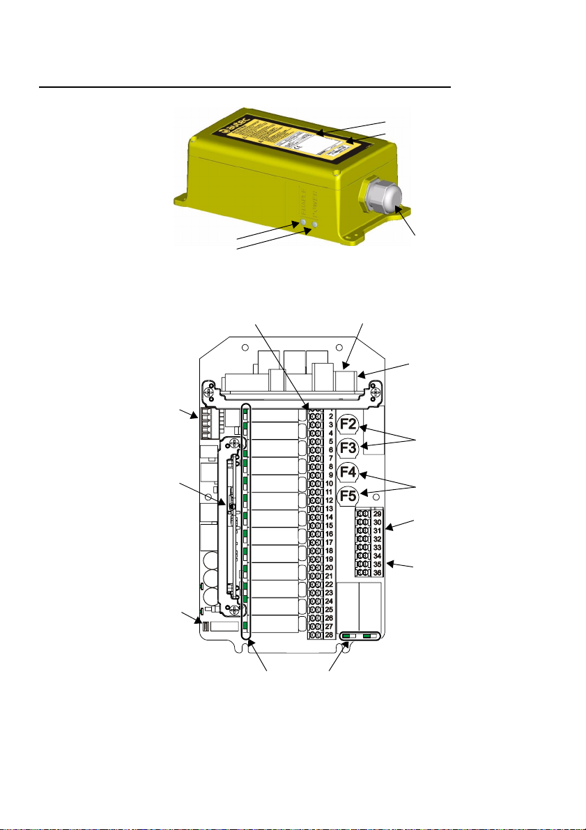
5.1 Descrizione unità ricevente G
Uscite comandi
Ingressi digitali
Modulo elettronico
DIP switch
Pressacavo
F1: fusibile per l’alimentazione
Connettore per l’alimentazione
Fusibili del circuito di SAFETY
Fusibili del circuito di STOP
Uscite SAFETY
Uscite STOP
Segnalazioni luminose interne
Fusibile F1.................................................................................... 1.6 A T 250 V (5x20 mm)
Fusibile F2 e F3............................................................................... 4 A T 250 V (5x20 mm)
Fusibile F4 e F5............................................................................... 4 A T 250 V (5x20 mm)
LIUAIR1AI3-01.fm
AUTEC - Serie AIR
14 Unità ricevente
Descrizione unità ricevente L
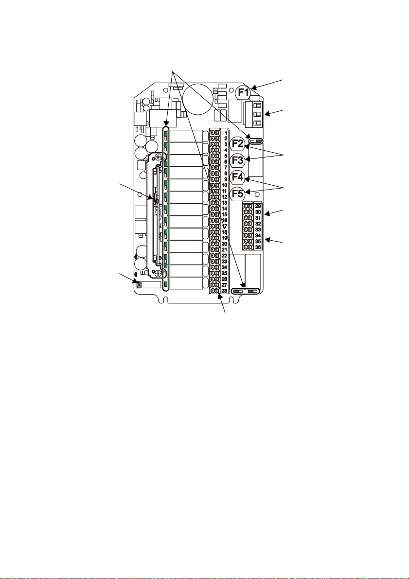
5.2 Descrizione unità ricevente L
Segnalazioni luminose interne
Fusibile per l’alimentazione
Connettore per l’alimentazione
Fusibili del circuito di SAFETY
Modulo elettronico
DIP switch
Uscite comandi
Fusibili del circuito di STOP
Uscite SAFETY
Uscite STOP
Fusibile F1.................................................................................... 1.6 A T 250 V (5x20 mm)
Fusibile F2 e F3............................................................................... 4 A T 250 V (5x20 mm)
Fusibile F4 e F5............................................................................... 4 A T 250 V (5x20 mm)
5.3 Funzionamento
5.3.1 Modulo elettronico
Sul modulo elettronico è presente la chiave di codice che contiene anche i dati di configurazione del radiocomando. Senza questa chiave di codice, l’unità ricevente non può funzionare.
5.3.2 DIP switch
Il DIP switch 1 serve per impostare la banda di frequenza (vedere capitolo 2)
Il DIP switch 2 deve sempre essere impostato in OFF: non modificare.
5.3.3 Segnalazioni luminose esterne
Il LED ENABLE è spento: l’unità ricevente e trasmittente non comunicano tra loro.
Il LED ENABLE lampeggia: l’unità è pronta a ricevere i comandi inviati dall’unità trasmitten-
te.
LED POWER è acceso: l’unità ricevente è alimentata.
AUTEC - Serie AIR

Unità ricevente 15
Avvertenze per l’installazione
5.3.4 Segnalazioni luminose interne
L’attivazione di ciascun relè presente sulla scheda base è segnalata da un LED nei pressi
del relè stesso.
5.3.5 Uscite comandi
La corrispondenza fra comando inviato dall’unità trasmittente e uscita attivata nell’unità ricevente è indicata nella scheda tecnica.
5.4 Avvertenze per l’installazione
L’installazione e il collaudo del radiocomando devono essere eseguiti esclusivamente da
personale qualificato, in possesso delle conoscenze tecniche necessarie per il compimento
di tale operazione e abilitato secondo le disposizioni del Paese in cui si effettua tale operazione. Solo una corretta installazione può assicurare un utilizzo sicuro del radiocomando.
Oltre a tutte le indicazioni imposte dal costruttore della macchina, un installatore dovrà sempre rispettare le seguenti avvertenze.
5.4.1 Generali
Rispettare e applicare quanto previsto da tutte le norme di riferimento del settore applicativo (es. EN IEC 60204-32 per macchine di sollevamento).
Per effettuare una corretta installazione, rispettare sempre le indicazioni fornite
nella scheda tecnica.
5.4.2 Posizionamento e fissaggio
L’unità ricevente deve essere posizionata:
- in modo che sia facilmente accessibile in caso di necessità
- verticalmente, con il pressacavo o spina verso il basso e possibilmente in vista dell’area di lavoro
- ad almeno 50 cm da oggetti metallici circostanti e mai all’interno di contenitori metallici chiusi.
La non osservanza di questa avvertenza può limitare il raggio d’azione del radiocomando.
Fissare l’unità ricevente in quattro punti utilizzando i fori predisposti sulla custodia. Nel caso di installazione su macchine che emettono vibrazioni, si consiglia di fissare l’unità ricevente alla macchina interponendo appositi
antivibranti.
Non perforare in nessun caso l’unità ricevente.
LIUAIR1AI3-01.fm
AUTEC - Serie AIR

16 Unità ricevente
Avvertenze per l’installazione
5.4.3 Posizionamento dell’antenna
L'antenna si trova all'interno dell'unità ricevente. Pertanto, installare l’unità ricevente in modo che schermi, strutture o materiali non ostacolino il collegamento radioelettrico; in particolare:
- l’unità ricevente non deve essere all’interno di contenitori metallici chiusi
- l’unità ricevente deve essere collocata ad almeno 50 cm da oggetti metallici
circostanti.
La non osservanza di questa avvertenza può limitare il raggio d’azione del radiocomando
5.4.4 Cablaggio
L’alimentazione dell’unità ricevente deve passare obbligatoriamente attraverso
un interruttore onnipolare con distanza dei contatti di almeno 3 mm che consente di togliere l'alimentazione durante le operazioni di installazione, di cablaggio e/o di manutenzione.
L’alimentazione dell’unità ricevente deve essere protetta contro il cortocircuito
attraverso l’uso di un dispositivo con un’adeguata capacità di interruzione (es.
fusibile).
Prestare particolare attenzione alle correnti e alle tensioni presenti nelle uscite
SAFETY e STOP: esse non devono superare i valori massimi consentiti.
Il contatto del relè SAFETY deve essere collegato in serie al comune dei comandi di movimento quando è necessaria la protezione dai movimenti non voluti
dalla posizione di riposo.
fusibile
ingresso comune
comune dei comandi di movimento
comune dei comandi di selezione
Raggruppare i fili di cablaggio lontano dal modulo elettronico al fine di evitare
interferenze e pericoli relativi alla sicurezza elettrica.
Nell’unità ricevente il circuito di STOP è realizzato con due contatti collegati in
serie tramite il ponte fra i morsetti 34 e 35 (cablaggio standard del costruttore).
Se la macchina richiede un circuito di STOP a due contatti (quattro fili) separati
è possibile rimuovere tale ponte. In questo caso è responsabilità dell’installatore realizzare un cablaggio che garantisca il livello di sicurezza richiesto.
Valutare il cablaggio del radiocomando, ricordando che se per motivi applicativi e/o funzionali, l’uscita dedicata al clacson, alla sirena o al lampeggiante della
macchina è utilizzata per un altro comando, non tutte le procedure del “Menu
di Configurazione” possono essere successivamente disponibili.
AUTEC - Serie AIR

Batteria AIRBM3V7L 17
Avvertenze per l’installazione
5.4.5 Al termine dell’installazione
Verificare che nel corso dell’installazione non siano state eseguite operazioni
che rendano inefficaci i meccanismi di sicurezza previsti sul radiocomando e/o
presenti all’interno della macchina.
Verificare che sia impostata la banda di frequenze permessa nel Paese di utilizzo del radiocomando (vedere capitolo 2).
Richiudere correttamente l’unità ricevente per non comprometterne il grado di
protezione alle polveri e all’acqua: verificare l'integrità della guarnizione, sovrapporre correttamente le parti dell'involucro e avvitare le viti presenti.
5.4.6 Collaudo
Dopo l’installazione ed il cablaggio dell’unità ricevente, eseguire il collaudo del
sistema “macchina+radiocomando”, verificando l’esatta corrispondenza tra i
comandi inviati e le manovre effettuate (in particolare il comando di STOP).
L’installatore deve verificare e compilare in tutte le sue parti la “Scheda Tecnica” apponendo su di essa la data di messa in funzione dell’impianto, il proprio
timbro e la propria firma.
In caso di malfunzionamento, si deve mettere fuori servizio il sistema “macchina+radiocomando” fino alla completa eliminazione del problema.
6 Batteria AIRBM3V7L
La batteria AIRBM3V7L è stata ideata e pensata
per essere utilizzata nelle unità trasmittenti dei
radiocomandi serie AIR.
batteria
coperchio
La batteria AIRBM3V7L deve essere
sempre utilizzata nella relativa sede di
alloggiamento presente nelle unità
trasmittenti della serie AIR.
È obbligatorio chiudere sempre la
batteria all’interno dell’unità trasmittente con la vite e il coperchio relativi:
non utilizzare mai l’unità trasmittente
se la batteria non è chiusa all’interno
del coperchio avvitato.
sede di alloggiamento
della batteria
Una batteria può essere caricata e scaricata centinaia di volte, ma con l'uso si esaurisce.
Se non utilizzata, una batteria anche completamente carica si scarica con il passare del tempo.
Quando l’autonomia risulta notevolmente ridotta rispetto al normale, è necessario sostituire
la batteria.
LIUAIR1AI3-01.fm
AUTEC - Serie AIR

18 Batteria AIRBM3V7L
Dati tecnici
Usare esclusivamente batterie originali Autec e caricare la batteria solo con alimentatori forniti da Autec per questa unità.
L'uso improprio di una batteria e di un alimentatore può comportare il pericolo
di incendio, deflagrazione o altri pericoli.
L'uso di batterie diverse da AIRBM3V7L fa decadere qualsiasi garanzia.
Non utilizzare mai batterie che risultino danneggiate.
Autec declina ogni responsabilità per qualsiasi utilizzo non conforme alle prescrizioni
e alle indicazioni fornite e per qualsiasi danno che possa essere comunque conseguenza di un uso improprio, erroneo o irragionevole della batteria.
6.1 Dati tecnici
Batteria AIRBM3V7L: tipo / tensione / capacità ....................... Li-ion / 3.7 V / 1300 mAh
Tempo massimo di ricarica .............................................................................................. 4 h
Temperatura ambiente di ricarica............................................................. da +5°C a +45°C*
Temperatura ambiente di utilizzo ............................................................ da -20°C a +55°C*
Temperatura ambiente di stoccaggio consigliata .................................... da -20°C a +45°C*
* nota: le temperature estreme riducono la capacità e la durata della batteria.
6.2 Avvertenze per l’uso
È consigliabile caricare la batteria prima del suo primo utilizzo.
Se danneggiate, le batterie potrebbero surriscaldarsi o incendiarsi; pertanto,
non si deve:
- mettere in corto circuito i poli della batteria
- smontare, tagliare, aprire, comprimere, deformare, forare, rompere, modificare, o manomettere le batterie
- tentare di inserire oggetti estranei nelle batterie
- immergerle o esporle all'acqua o ad altri liquidi.
In caso di contatto con materiale proveniente da una batteria danneggiata, lavare immediatamente la parte colpita con acqua e sapone per almeno 15 minuti
e consultare un medico.
Al fine di garantire la massima durata della batteria nel tempo, evitare:
- l’utilizzo e la ricarica fuori dai limiti di temperatura riportati nei “Dati Tecnici”
- l’immagazzinamento (o inutilizzo) per più di sei mesi
- l’esposizione a fonti di calore
- l’immagazzinamento in ambienti umidi.
AUTEC - Serie AIR

Docking station 19
Rottamazione
6.3 Rottamazione
Riciclare le batterie applicando le disposizioni locali: nell’Unione Europea
sono previsti modi distinti per la raccolta e il riciclaggio di batterie in conformità alla Direttiva 2006/66/CE e successive modifiche.
Non gettare le batterie assieme ai rifiuti domestici o nel fuoco in quanto potrebbero esplodere.
7 Docking station
La docking station AIRDOCK01 serve per caricare le unità trasmittenti dei radiocomandi serie AIR tramite l’adattatore, da parete FRA012-S05 o da auto CLA05D-050A, fornito con il
radiocomando.
Alimentatore CLA05D-050ADocking station Alimentatore FRA012-S05-**
**: IE: spina europea
IU: spina americana
IA: spina australiana
Un’unità trasmittente A8 deve essere caricata esclusivamente tramite la
docking station AIRDOCK01 e l’adattatore, da parete FRA012-S05 o da auto
CLA05D-050A, forniti da Autec con il radiocomando.
L'uso di una docking station e di un alimentatore diversi da quelli forniti fa decadere qualsiasi garanzia.
Non utilizzare mai la docking station e l’alimentatore se sono danneggiati.
L'uso improprio di una docking station e di un alimentatore può comportare il
pericolo di incendio, deflagrazione o altri pericoli.
Autec declina ogni responsabilità per qualsiasi utilizzo non conforme alle prescrizioni
e alle indicazioni fornite e per qualsiasi danno che possa essere comunque conseguenza di un uso improprio, erroneo o irragionevole della docking station e dell’alimentatore.
LIUAIR1AI3-01.fm
AUTEC - Serie AIR

20 Docking station
Collegamento tra docking station e alimentatore
7.1 Collegamento tra docking station e alimentatore
Per collegare la docking station all’alimentatore è
necessario inserire lo spinotto dell’alimentatore nel-
la presa della docking station.
L’alimentatore deve essere alimentato da
una presa facilmente raggiungibile e
scollegabile.
Spinotto
7.1.1 Ricarica
Quando è necessario caricare la batteria accertarsi che la macchina si trovi in
uno stato sicuro in modo che non possa causare pericoli (es. non lasciare mai
il carico sospeso). Durante la carica non è possibile inviare comandi dall’unità
trasmittente.
Effettuare la carica dell’unità in luoghi chiusi.
Dopo aver alimentato la docking station con l’apposito alimentatore:
- inserire l’unità A8 nella docking station: inizia la carica indicata dal LED rosso acceso fisso
(durata massima 4 h)
- estrarre l’unità A8 dalla docking station quando necessario.
AUTEC - Serie AIR

Manutenzione del radiocomando 21
Manutenzione ordinaria
8 Manutenzione del radiocomando
Le istruzioni che seguono forniscono le informazioni per eseguire in sicurezza le operazioni
di manutenzione ordinaria e straordinaria del radiocomando.
Esse devono essere integrate:
- dalle istruzioni fornite dal costruttore della macchina
- dalle indicazioni dell'installatore del radiocomando sulla macchina
- dalle disposizioni di legge in materia di sicurezza sul lavoro e di prevenzione degli infortuni
in vigore nel Paese di utilizzo del radiocomando.
Tutti gli interventi di messa a punto di controllo e di manutenzione del radiocomando vanno
verificati e registrati dal Responsabile della Manutenzione della macchina.
In caso di guasto o parti danneggiate, si deve mettere fuori servizio il sistema
“macchina+radiocomando” fino alla completa eliminazione del problema.
Prima di ogni intervento di manutenzione, togliere l’alimentazione all’unità ricevente.
Dopo ogni intervento di manutenzione:
- verificare sempre che i comandi inviati dall’unità trasmittente attivino esclusivamente le manovre previste
- nel caso in cui l’unità trasmittente sia stata aperta, richiuderla correttamente
per non comprometterne il grado di protezione alle polveri e all’acqua: verificare l'integrità della guarnizione, sovrapporre correttamente le parti dell'involucro e avvitare le viti presenti.
8.1 Manutenzione ordinaria
La manutenzione ordinaria è l'operazione o l'insieme delle operazioni necessarie per mantenere le normali condizioni di utilizzo del radiocomando attraverso interventi di messa a punto,
di verifica, di sostituzione programmata delle parti, che siano resi necessari da un uso normale del prodotto.
Tutte le istruzioni riportate devono essere eseguite ad ogni messa in servizio, cioè:
- ad ogni installazione o montaggio del radiocomando e/o della macchina
- ad ogni modifica dell'ubicazione/collocazione della macchina
- dopo una manutenzione straordinaria.
La manutenzione ordinaria secondo le istruzioni contenute in questo manuale è fondamentale per il funzionamento sicuro del radiocomando.
Particolari applicazioni possono richiedere interventi di manutenzione ordinaria più specifici
e con tempistiche diverse (es. nel caso di ambienti lavorativi sporchi, di applicazioni gravose
o di utilizzo molto frequente, può essere necessario effettuare alcuni interventi con una frequenza maggiore su decisione del responsabile della sicurezza del cantiere).
LIUAIR1AI3-01.fm
AUTEC - Serie AIR

22 Manutenzione del radiocomando
Manutenzione ordinaria
8.1.1 Manutenzione ordinaria giornaliera
Prima di iniziare a lavorare:
- accertarsi che i contatti per la carica siano sempre puliti
- verificare che le guarnizioni dei tasti siano integri, morbidi ed elastici
- verificare che i simboli del pannello dell’unità trasmittente siano ben visibili ed eventualmente sostituire il pannello stesso
- controllare la leggibilità e l'integrità delle tre targhette dell’unità trasmittente
- verificare il corretto funzionamento meccanico del pulsante STOP.
Durante il normale funzionamento:
- controllare che l'unità trasmittente sia strutturalmente integra
- fare attenzione che sull’unità trasmittente non si depositino materiali (es. cemento, sabbia,
calce, polvere) che possano comprometterne l’utilizzo e la sicurezza.
Dopo aver utilizzato il radiocomando:
- pulire l’unità trasmittente: non usare mai solventi o prodotti infiammabili/corrosivi e non utilizzare idropulitrici ad alta pressione o apparecchi a vapore
- immagazzinare l'unità trasmittente in ambienti puliti ed asciutti.
8.1.2 Manutenzione ordinaria trimestrale
Ogni tre mesi:
- rimuovere la polvere o accumuli di altro materiale dall'unità ricevente: per pulire non usare
mai solventi o prodotti infiammabili/corrosivi e non utilizzare idropulitrici ad alta pressione
o apparecchi a vapore
- controllare che l'unità ricevente sia strutturalmente integra
- verificare l’integrità e la connessione del cablaggio dell’unità ricevente
- verificare che i simboli del pannello dell’unità ricevente siano ben visibili ed eventualmente
sostituire il pannello stesso
- controllare la leggibilità e l'integrità delle targhette dell’unità ricevente.
8.1.3 Manutenzione ordinaria semestrale
Ogni sei mesi:
- verificare il corretto funzionamento dei contatti di tutti i relè dell'unità ricevente, controllando la chiusura del contatto all'attivazione della corrispondente manovra e apertura del contatto alla disattivazione della manovra
- verificare la corretta corrispondenza tra comandi inviati e manovre eseguite dalla macchina
- verificare che il contatto del relè SAFETY sia aperto quando nessun comando di movimento è inviato. Questa manutenzione è importante per la sicurezza: è necessario registrare
questo intervento (data, firma, commenti) come evidenza che la verifica è stata regolarmente effettuata. Conservare la registrazione assieme agli altri documenti dell'installazione.
AUTEC - Serie AIR

Manutenzione del radiocomando 23
Manutenzione straordinaria
8.2 Manutenzione straordinaria
La manutenzione straordinaria è l'operazione o l'insieme delle operazioni di riparazione rese
necessarie da guasti, rotture o malfunzionamenti del radiocomando, che hanno lo scopo di
ripristinare le condizioni d'uso e di funzionamento originarie.
Prima di far intervenire i tecnici del servizio di assistenza, è opportuno:
- aver letto e capito tutti i documenti relativi al radiocomando, verificando di aver eseguito
correttamente tutte le istruzioni in essi riportate
- aver eseguito le istruzioni per ricercare i possibili malfunzionamenti e le loro cause.
Eventuali guasti possono essere riparati esclusivamente da personale autorizzato (interpellare il servizio di assistenza del costruttore della macchina), utilizzando soltanto
parti di ricambio originali Autec.
Per rendere possibile un intervento più veloce ed efficace, devono essere comunicati i dati
per una corretta e completa identificazione del radiocomando:
- numero di matricola (S/N) del radiocomando
- data di acquisto (riportata sul certificato di garanzia)
- anomalia riscontrata
- indirizzo e numero di telefono del luogo in cui è utilizzato (e il nome del responsabile da
contattare)
- ditta fornitrice.
8.3 Malfunzionamenti
Quando il radiocomando non funziona, è necessario:
- avvicinare l’unità trasmittente all’unità ricevente al fine di evitare disturbi ed interferenze radio
- controllare se il problema interessa il radiocomando o la macchina.
Perciò, prima di qualunque verifica, provare a comandare la macchina tramite una postazione di comando diversa dal radiocomando, se presente.
Se il problema persiste, il problema interessa la macchina stessa.
ricercare il malfunzionamento del radiocomando secondo quanto indicato di seguito.
LIUAIR1AI3-01.fm
AUTEC - Serie AIR

24 Manutenzione del radiocomando
Malfunzionamenti
8.3.1 Segnalazioni dell’unità trasmittente
Nel caso in cui il problema persista dopo avere attuato la soluzione di seguito indicata, contattare il servizio di assistenza.
LED Segnalazioni Possibile causa Soluzioni
Avviare il radiocomando.
Acceso fisso
Verde
Rosso
Verde e Rosso
velocemente
(un lampeggio
Acceso fisso
all’accensione
Lampeggia 2 volte
all’accensione
Lampeggia 3 volte
all’accensione
Acceso per 2 s
velocemente
Lampeggiano
alternativamente
All’accensione
è acceso fisso
Lampeggia
Lampeggia
lentamente
al secondo)
al secondo
al secondo
Lampeggia
lentamente
Lampeggia
il LED verde
lampeggia e
Il LED rosso
L’unità trasmittente e ricevente non comunicano tra loro.
Il radiocomando non è avviato.
Il radiocomando è avviato.
Il pulsante STOP è attivo o
guasto.
Almeno uno dei comandi è attivo o guasto.
L’unità è scarica. Ricaricare l’unità.
L’unità non funziona correttamente.
L’autonomia è di circa 4 h.
Rimangono 10 min di autonomia.
Mancano 30 s allo spegnimento automatico dell’unità.
L’unità trasmittente non è accoppiata con alcuna unità ricevente.
Se il radiocomando non si avvia
verificare che l’unità ricevente sia
alimentata.
Premere il pulsante START fino
al lampeggio lento del LED verde.
Vedere il paragrafo “Segnalazioni dell’unità ricevente”.
Disinserire il pulsante STOP.
Portare gli attuatori in posizione
di riposo.
Contattare il servizio di assistenza.
Appena possibile, portare il sistema “macchina+radiocomando” in
uno stato sicuro e ricaricare l’unità.
Portare il sistema “macchina+radiocomando” in uno stato sicuro
e ricaricare l’unità.
Premendo un qualsiasi tasto si
azzera il tempo di autospegnimento.
Effettuare la procedura di PAIR
per accoppiare l’unità trasmittente a un’unità ricevente.
AUTEC - Serie AIR

Manutenzione della macchina 25
Malfunzionamenti
8.3.2 Segnalazioni dell’unità ricevente
Nel caso in cui il problema persista dopo avere attuato la soluzione di seguito indicata, contattare il servizio di assistenza.
LED Segnalazioni Possibile causa Soluzioni
La spina di collegamento tra
Agganciare correttamente la spina di collegamento.
Controllare che i fili dell’alimentazione siano collegati correttamente e che il valore
dell’alimentazione sia all’interno
dei limiti specificati nei dati tecnici.
Controllare il corretto cablaggio
delle uscite e che il valore dell’alimentazione sia all’interno dei limiti specificati nei dati tecnici.
Avviare il radiocomando.
Avviare il radiocomando.
Verificare che i comandi inviati
attivino i corrispondenti relè e che
i relè tornino in posizione di riposo al rilascio del comando.
POWER
ENABLE
radiocomando e macchina
non è connessa correttamente.
Il fusibile F1 è guasto. Sostituire il fusibile.
Spento
Alimentazione assente o errata.
Acceso Unità ricevente alimentata.
Spento
Lampeggia
L’unità trasmittente e ricevente non comunicano tra loro.
Radiocomando avviato: l’unità
è pronta a ricevere i comandi
dall’unità trasmittente.
9 Manutenzione della macchina
La manutenzione della macchina deve essere eseguita seguendo le istruzioni fornite dal costruttore della macchina e dall'installatore del radiocomando sulla macchina.
Quando si effettuano operazioni di manutenzione della macchina, togliere sempre l’alimentazione all’unità ricevente.
Scollegare tutte le connessioni elettriche dell’unità ricevente ogni volta che si
effettuano lavori di manutenzione sulla macchina (es. saldature).
10 Rottamazione
Per la rottamazione affidare il radiocomando al servizio di recupero differenziato dei rottami
esistente nel territorio.
LIUAIR1AI3-01.fm
AUTEC - Serie AIR

26 Rottamazione
Malfunzionamenti
AUTEC - Serie AIR

INDEX
1 Description of the AIR series' radio remote controls .............................................................. 28
1.1 How the radio remote control works ..................................................................................... 28
1.2 Applications ........................................................................................................................... 28
1.3 Technical data ....................................................................................................................... 29
1.4 Safety function: stop protection ............................................................................................. 30
1.5 Protection against unintended movements from the rest position ........................................ 30
1.6 Identifying the radio remote control ....................................................................................... 30
2 Conformity and frequencies ...................................................................................................... 30
2.1 Frequency band 433.050-434.790 MHz ............................................................................... 30
2.2 Frequency band 915-928 MHz ............................................................................................. 31
3 Risk assessment ........................................................................................................................ 32
3.1 Risk assessment for radio remote controlled machines ....................................................... 32
3.2 Staff training .......................................................................................................................... 33
3.3 Working conditions ................................................................................................................ 33
4 A8 transmitting unit .................................................................................................................... 34
4.1 Description of the A8 unit ...................................................................................................... 34
4.2 Operation .............................................................................................................................. 34
4.3 Warnings for use ................................................................................................................... 36
4.4 Recharging the A8 unit ......................................................................................................... 38
4.5 Docking station AIRDOCK01 ................................................................................................ 38
5 Receiving unit ............................................................................................................................. 39
5.1 Description of G type receiving unit ...................................................................................... 39
5.2 Description of type L receiving unit ....................................................................................... 40
5.3 Operation .............................................................................................................................. 40
5.4 Warnings for installation ........................................................................................................ 41
6 Battery AIRBM3V7L .................................................................................................................... 43
6.1 Technical data ....................................................................................................................... 44
6.2 Warnings for use ................................................................................................................... 44
6.3 Disposal ................................................................................................................................ 45
7 Docking station ........................................................................................................................... 45
7.1 Connecting the docking station and the power supply unit ................................................... 46
8 Radio remote control maintenance .......................................................................................... 47
8.1 Routine maintenance ............................................................................................................ 47
8.2 Special maintenance ............................................................................................................. 49
8.3 Malfunctions .......................................................................................................................... 49
9 Machine maintenance ................................................................................................................ 51
10 Disposal ....................................................................................................................................... 51
27
LIUAIR1AE3-01.fm AUTEC - AIR series

28 Description of the AIR series' radio remote controls
CAPTION
This symbol indicates an important warning that, if disregarded, leads
to a hazardous situation for people and property.
This symbol indicates a document that can be found in the specific section
@
on Autec's website.
The documentation must be kept for the whole life of the radio remote control: after
reading it, keep it on hand for future reference.
Contact Autec if any of the instructions and/or warnings provided in this document
are not clear. No part of this document may be reproduced, in any form or by any
means, without written permission of Autec (including recording and photocopying).
How the radio remote control works
1 Description of the AIR series' radio remote controls
1.1 How the radio remote control works
Industrial radio remote controls are used to control machines from a distance, without physical connection between the user and the machine (i.e. wires or connecting cables). They
consist of a portable transmitting unit, from which the user remotely controls the machine,
and a receiving unit installed on board the machine itself.
The two units constantly communicate with one another through a radio link. They automatically search for a free working frequency.
The two units use messages coded through an address that is unique (produced by Autec
only once) and univocal (specific for each radio remote control).
1.2 Applications
AIR series' radio remote controls can be installed on hoisting and material handling machines
(i.e. overhead cranes).
As required by standards ISO 12100 and ISO 14121, risk assessment must be carried out
for each machine (see chapter 3). The radio remote control can only be used if this assessment gives positive results. However, this radio remote control cannot be installed:
- on machines installed in places where equipment with explosion-proof characteristics is required
- on machines for moving, raising and transporting people.
- on machines that may generate dangerous situations if they stop due to the loss of radio
link
AUTEC - AIR series

Description of the AIR series' radio remote controls 29
Technical data
1.3 Technical data
Command response time (typical) .............................................................................100 ms
Working range (typical) .........................................................................................75 - 100 m
Stop time (typical) ..................................................................................................... 100 ms
Max. stop response time............................................................................................... 0.5 s
Performance Level of the safety function according to EN ISO 13849-1:
Stop protection...................................................................................................... cat 3 PL d
Transportation
Storage
Use
Radio remote con-
trol
Radio remote con-
trol
Transmitting unit
Receiving unit
Temperature
Class 2K4
-40°C to +70°C
(-40°F to +158°F)
Class 1K5
-40°C to +70°C
(-40°F to +158°F)
Class 4K4H
-20°C to +55°C
(-4°F to +130°F)
Class 4K4H
-20°C to +70°C
(-4°F to +158°F)
Relative
Humidity
Class 2K4
95%
Class 1K3
5% to 95%
Class 4K4H
4% to 100%
Class 4K4H
4% to 100%
Air Pressure
Class 2K4
70 kPa to 106 kPa
Class 1K5
70 kPa to 106 kPa
Class 4K4H
70 kPa to 106 kPa
Class 4K4H
70 kPa to 106 kPa
A8 transmitting unit
Power supply (battery AIRBM3V7L) .............................................................. Li-ion 3.7 V
Antenna..................................................................................................................... internal
Housing material ............................................................................................ PA 6 (20% fg)
Protection degree ......................................................................................... IP65 (NEMA 4)
Dimensions ................................................... 64.5 x 179 x 37.5 mm (2.54 x 7.05 x 1.48 In)
Weight .......................................................................................................... 250 g (0.55 Lb)
Run time (at 20°C / 68°F) .............................................................................................. 40 h
Receiving unit
Power supply ........................................................... 45 - 240 V (max 40 - 264 V 0.4 A)
optional for type G receiving unit .......................... 12 - 24 V (max 9 - 30 V 1 A)
Digital inputs voltage (for receiving unit G) ...............................10 - 60 V
(max 9 - 66 V )
Antenna..................................................................................................................... internal
STOP contact rated current ............................................................................. 4 A (250 V )
SAFETY contact rated current ......................................................................... 4 A (250 V )
Command contact rated current....................................................................... 6 A (250 V )
Housing material ............................................................................................ PA 6 (20% fg)
Protection degree ......................................................................................... IP65 (NEMA 4)
Dimensions ....................................................... 123 x 202 x 83 mm (4.84 x 7.95 x 3.23 In)
Weight ........................................................................................................... 1.2 kg (2.7 Lb)
LIUAIR1AE3-01.fm
AUTEC - AIR series

30 Conformity and frequencies
Safety function: stop protection
1.4 Safety function: stop protection
The stop function brings the machine to a safe state every time it is necessary to stop it due
to a potentially hazardous situation. Depending on the situation, this function can either be
deliberately activated by the operator through the STOP pushbutton, or it is automatically activated when the radio link is incorrect or interrupted (the receiving unit autonomously stops
the radio remote control).
1.5 Protection against unintended movements from the rest position
This safety function protects the system “machine+radio remote control” from unintended
movements, namely machine movements not activated intentionally by the user, but resulting from possible electrical and mechanical failure of the radio remote control.
Such safety function checks the neutral (rest) position of pushbuttons controlling the machine's movements. Each time one of those pushbuttons is operated, the transmitting unit
sends both the movement command and the SAFETY command.
1.6 Identifying the radio remote control
As required by standard IEC 60204-32 , each radio remote control is uniquely identified
through a serial number (SERIAL N.).
The SERIAL N. is provided in the identification plate in the two units.
2 Conformity and frequencies
AIR series radio remote controls can work at two different frequency bands:
- 433.050 - 434.790 MHz
- 915.000 - 928.000 MHz.
The radio remote controls' working frequency is defined by market-specific
laws and standards. In order for the system “machine+radio remote control” to
be compliant and therefore to be used, it shall comply with such laws and
standards: if it does not, the system may be impounded by competent bodies.
Autec cannot be held responsible if the radio remote control is set with forbidden frequencies.
2.1 Frequency band 433.050-434.790 MHz
2.1.1 Conformity
Each AIR series' radio remote control working in the frequency band 433.050-434.790 MHz
complies with the (R&TTE) Directive 1999/5/EC and its essential requirements.
Each radio remote control is also in conformity with the harmonised standards provided in
the EC Declaration of Conformity.
@
You can find the EC Declaration of Conformity in the specific section of Autec website,
under “After Sales Service”.
AUTEC - AIR series

Conformity and frequencies 31
Frequency band 915-928 MHz
2.1.2 Frequencies
The radio link between the units of Autec AIR series radio remote controls is built at one of
the frequencies permitted by the European standards in force when the system is put on the
market.
Frequencies used in the frequency band 433.050-434.790 MHz ..................................... 64
RF power................................................................................................................... <1 mW
Channel spacing ........................................................................................................ 25 kHz
2.1.3 Market
Air series' radio remote controls working in the frequency band 433.050-434.790 MHz can
be used within the EU (European Union) and the EFTA (European Free Trade Association).
2.2 Frequency band 915-928 MHz
2.2.1 Conformity
Each AIR series' radio remote control working in the frequency band 915-928 MHz complies
with the essential requirements of the following regulations:
- FCC (Federal Communication Commission) Part 15
- IC (Industry Canada) RSS-102
Unit FCC ID IC number
A8 OQA-A08LA0AM 9061A-A08LA0AM
Receiving unit G OQA-RGAAA00M 9061A-RGAAA00M
Receiving unit L OQA-RLBCA00M 9061A-RLBCA00M
Operation is subject to the following two conditions:
(1) this device may not cause harmful interference, and
(2) this device must accept any interference received, including interference that may cause
undesired operation.
Changes or modifications not expressly approved by the party responsible for compliance
could void the user’s authority to operate the equipment.
2.2.2 Frequencies
The radio link between the units of Autec AIR series radio remote controls is built at one of
the frequencies permitted by the US and Canadian standards in force when the system is put
on the market.
Frequencies used in the frequency band 915-928 MHz ................................................. 256
RF power............................................................... complies with FCC and IC requirements
Channel spacing ........................................................................................................ 50 kHz
2.2.3 Market
Air series' radio remote controls working in the frequency band 915-928 MHz can be used in
the US and Canadian markets.
LIUAIR1AE3-01.fm
AUTEC - AIR series

32 Risk assessment
Risk assessment for radio remote controlled machines
3 Risk assessment
Always evaluate whether the machine can be radio remote controlled. In fact, as required by
technical standards specific to the market where the system “machine+radio remote control”
is used, each machine must undergo risk assessment and risk analysis.
The radio remote control can only be installed if this assessment gives positive results.
The machine manufacturer and/or the person who decides upon radio remote
control installation and use is responsible for this risk assessment.
Autec cannot be held responsible if this assessment has not been carried out correctly or is incomplete.
If required by the risk assessment, draw up protection measures to prevent, reduce and report potential hazard situations.
3.1 Risk assessment for radio remote controlled machines
When carrying out risk assessment for the machine or for the system where the radio remote
control is installed, the following must be considered:
- some machines cannot be radio remote controlled: check for forbidden applications (see
paragraph 1.2)
- the radio link between the two units may be interrupted due to persistent disturbance or
interference.
- all warnings related to installation, use and maintenance provided by Autec must be taken
into account
3.1.1 Aspects related to radio link
Whenever the radio link is interrupted (i.e. stop, low battery, automatic switch off, receiving
unit not powered):
- all outputs in the receiving unit are disabled: if this generates a hazardous situation, the
corresponding commands on the machine must be kept active
- it is not possible to enable or disable the machine commands until the radio remote control
is started up again.
3.1.2 Delay in command response time
Due to the characteristics of radio propagation (i.e.: EM interference, out-of-working-range
condition), a delay up to the "Maximum stop time" may occasionally occur from the moment
a command in the transmitting unit is released to the moment its corresponding output in the
receiving unit is deactivated.
Those who decide upon the installation of the radio remote control must make sure that this
delay never leads to a dangerous situation in the specific uses.
3.1.3 Protection from unintended activation
The transmitting unit housing is manufactured so that it protects the actuators from unintentional activation, while meeting at the same time the operating needs, the comfort requirements and law limits.
AUTEC - AIR series

Risk assessment 33
Staff training
Assessment shall be made to establish possible additional protection measures for the actuators (i.e. commands requiring two-hand operation, “dead-man” function) if particular environments, equipment and working modes could cause accidental bumps to the actuators.
3.2 Staff training
All installation, usage and maintenance operations must be carried out by qualified technicians who are suitably trained with respect to:
- warnings resulting from risk assessment
- regulations and reference laws
- instructions and warnings provided in the documents related to the industrial radio remote
control and to the radio remote controlled machine
- instructions provided by those who install the radio remote control on the machine and by
the person in charge for workplace safety where the system machine+radio remote control
is used.
3.3 Working conditions
To guarantee correct radio remote control operation, all current regulations regarding safety
at work and accident prevention should be respected. All applicable standards and regulations valid in the user country regarding the use of both the machine and the radio remote
control must always be respected.
Autec cannot be held responsible if the radio remote control is used in unlawful working conditions.
LIUAIR1AE3-01.fm
AUTEC - AIR series

34 A8 transmitting unit
Description of the A8 unit
4 A8 transmitting unit
4.1 Description of the A8 unit
LEDs
STOP pushbutton
Command pushbuttons
FUNCTION
pushbutton
Screw and battery cover
Technical data plate
Identification plate
START
Contacts for recharge
pushbutton
4.2 Operation
4.2.1 Start up with PIN code
As required by standard IEC 60204-32, the radio remote control start up is protected by a PIN code, in order to prevent non authorised use of the machine.
During the start up phase, press each pushbutton within 3 seconds from the release of the
previous pushbutton, or the transmitting unit will switch off.
Start up through factory-set PIN
When the receiving unit is powered on, perform the following procedure:
1) press the START pushbutton until the green LED illuminates
2) press the FUNCTION pushbutton
3) press the START pushbutton until the green LED blinks slowly.
STOP
1
R
2
G
34
S1 S2
STARTFUNCT.
STOP
1
R
2
G
34
S1 S2
STARTFUNCT.
STOP
1
R
2
G
34
S1 S2
STARTFUNCT.
AUTEC - AIR series
1) START 2) FUNCTION 3) START

A8 transmitting unit 35
Operation
Start up through customised PIN
If the risk assessment requires this, the PIN code may be modified to prevent unauthorised
use.
The procedure to set a customised PIN is provided in the document “Menu of Trans-
@
mitting Unit (MTU)”; you can find this document in the dedicated section on Autec's
website.
When the receiving unit is powered on, perform the following procedure:
1) press the START pushbutton until the green LED illuminates
2) press the pushbutton sequence PIN 1, PIN 2 and PIN 3 related to the PIN code provided
in the technical data sheet (if PIN 1 and/or PIN 3 is the START pushbutton, it is not to be
considered as part of the code sequence)
3) press the START pushbutton until the green LED blinks slowly.
STOP
1
R
2
G
34
S1 S2
STARTFUNCT.
STOP
1
R
2
G
34
S1 S2
STARTFUNCT.
STOP
1
R
2
G
34
S1 S2
STARTFUNCT.
STOP
1
R
2
G
34
S1 S2
STARTFUNCT.
STOP
1
R
2
G
34
S1 S2
STARTFUNCT.
PIN 1 PIN 2 PIN 3
1) START 3) START
2) PIN
4.2.2 Command activation
Press pushbuttons related to the commands you want to carry out.
4.2.3 Light signals during operations
Green LED
- steady on: transmitting and receiving unit do not communicate with each other
- blinks fast: the radio remote control starts when the
START pushbutton is pressed
- blinks slowly (one blink per second): it is possible to
send commands.
STOP
PD5580-00
Red LED
Green LED
Red LED
- steady on at power on: the STOP pushbutton is activated or damaged
- blinks twice per second at power on: at least one of the commands is activated or damaged
- blinks 3 times per second at power on: the unit is discharged
- on for 2 s: the unit does not work correctly
- blinks slowly: approx. 4 h run time left
- blinks fast: 10 min run time left.
LIUAIR1AE3-01.fm
AUTEC - AIR series

36 A8 transmitting unit
Warnings for use
Signals from the other four LEDs depend on the function matching the FUNCTION pushbutton (or on digital inputs, if wired on the G receiving unit).
4.2.4 FUNCTION pushbutton
The FUNCTION pushbutton can be matched with different relay functions on the receiver's
side (see technical data sheet).
4.2.5 STOP
The STOP pushbutton can only be pressed when it is necessary to immediately stop the machine when a dangerous condition occurs.
When the STOP pushbutton is pressed, the machine stops and the transmitting unit switches
off.
To start working again after the STOP pushbutton has been pressed, do the following:
- make sure that the working and usage conditions are safe
- pull or turn the STOP pushbutton in the arrow direction to unlock it
- start up the radio remote control.
In accordance with the EN ISO 13849-1, the value of B
for the STOP pushbutton is 6050.
10d
4.2.6 Switching off
The A8 unit automatically switches off in the following cases:
- voluntary switch off when the START pushbutton and immediately afterward the FUNCTION pushbutton are deeply pressed until the red LED illuminates
- as a response when the STOP pushbutton is pressed
- automatic switch off when there are no enabled commands for a predetermined timeframe.
This timeframe is provided tin the technical data sheet (SWITCH-OFF).
Before the A8 unit switches off automatically, the green and red LEDs blink alternating for
30 seconds.
4.3 Warnings for use
In addition to all instructions provided by the machine manufacturer, by the installer of the
radio remote control and by the person responsible for the safety of the work area, users shall
always respect the following warnings.
Before starting to work, the user shall do the following:
- stand in a position that allows the direct supervision of the remote controlled
machine and its load, and stay in a place ensuring safety conditions in respect of other operations and/or activities and/or processes that are carried
out in the working environment;
- never start up or use the transmitting unit if the working conditions present
the risk of losing balance or tripping;
- always check that the mechanical operation of the STOP pushbutton is correct. If it is impossible or difficult to press this pushbutton, do not use the radio remote control;
AUTEC - AIR series

A8 transmitting unit 37
Warnings for use
- only start up the transmitting unit when starting work: improper use may
cause hazardous situations;
- never start up or use the transmitting unit in closed spaces, with the machine
not in sight, or outside the radio remote control working range: in such cases
it is in fact still possible to build a radio link, thus causing the risk that unwanted commands be carried out by the machine;
- get familiar with the correspondence between the pushbuttons and the machine's movements (this is indicated in the attached technical data sheet) and
learn symbols on the panel of the A8 unit (symbols used are defined by the
machine manufacturer and/or installer depending on the machine's operation
and functions).
During normal operation, the user shall do the following:
- visually and directly follow all movements of the machine and its load and remain inside the radio remote control working range;
- use the transmitting unit in a simple and comfortable way, avoiding accidental falls. The pouch supplied with the radio remote control is used for this purpose;
- pay particular attention to warnings and visual/acoustic signals, and take all
measurements and steps to avoid that movements of the remote controlled
machine leads to hazardous situations for people and/or property;
- pay attention to the entire work area. Immediately press the STOP pushbutton
when a hazardous situation occurs;
- pay attention to the low battery signals. The A8 unit cannot be used during
the charging process; all dangerous operations (i.e. hanging load) must
therefore be brought to an end before the battery is completely flat;
- in case of malfunction, disable the system “machine+radio remote control”
until the problem has been completely solved.
After using the radio remote control, the user shall do the following:
- switch off the transmitting unit when work is stopped or temporarily interrupted. Do not leave the load hanging (even while recharging the unit);
- never leave the transmitting unit unattended if it is on.
LIUAIR1AE3-01.fm
AUTEC - AIR series

38 A8 transmitting unit
Recharging the A8 unit
4.4 Recharging the A8 unit
The A8 unit contains a rechargeable battery; the provided battery is partially charged.
To correctly use the A8 unit and its battery, the related chapter shall be fully understood and
kept into account.
First power on the docking station with its power supply unit and then:
1) insert the A8 unit into the docking station: a steady on red
LED indicates that charging has started (max. 4 h)
1b
2) remove the A8 unit from the docking station when necessary
Note: when the green LED switches on, the A8 unit is completely charged.
Charge the unit at a temperature between 5°C and 45°C.
Indication of A8 unit run time
Perform the following procedure to check the transmitting unit's run time:
1) switch off the transmitting unit and unlock the STOP pushbutton
2) keep pushbuttons S1 and START pressed until the 3 left LEDs illuminate
showing the unit's run time (3 illuminated LEDs correspond to the highest
run time).
Run time indication disappears after some seconds.
1
2
3
R
1
G
2
4
34
MAX. MIN.
1
R
2
G
3
R
G
4
1a
S1
START
2b
2a
STOP
1
R
2
G
34
S1 S2
STARTFUNCT.
4.5 Docking station AIRDOCK01
The docking station AIRDOCK01 is used to recharge the A8 unit.
Plug in the adapter in the socket on the back of the docking station.
The adapter works with 100 - 240 V (optional 10 - 30 V ).
To correctly use the docking station and its power supply unit, respect
the indications given in the related chapter.
AUTEC - AIR series

Receiving unit 39
Description of G type receiving unit
5 Receiving unit
Technical data plate
Identification plate
ENABLE LED
POWER LED
5.1 Description of G type receiving unit
Command outputs
Digital inputs
Electronic module
DIP switches
Cable gland
F1: power supply fuse
Connector for power supply
Fuses of SAFETY circuit
Fuses of STOP circuit
SAFETY outputs
STOP outputs
Internal light signals
Fuse F1 ......................................................................................... 1.6 A T 250 V (5x20 mm)
Fuses F2 and F3 ............................................................................. 4 A T 250 V (5x20 mm)
Fuses F4 and F5 ............................................................................. 4 A T 250 V (5x20 mm)
LIUAIR1AE3-01.fm
AUTEC - AIR series

40 Receiving unit
Description of type L receiving unit
5.2 Description of type L receiving unit
Internal light signals
Power supply fuse
Connector for power supply
Fuses of SAFETY circuit
Electronic module
DIP switches
Command outputs
Fuses of STOP circuit
SAFETY outputs
STOP outputs
Fuse F1 ......................................................................................... 1.6 A T 250 V (5x20 mm)
Fuses F2 and F3 ............................................................................. 4 A T 250 V (5x20 mm)
Fuses F4 and F5 ............................................................................. 4 A T 250 V (5x20 mm)
5.3 Operation
5.3.1 Electronic module
The electronic module contains the address key, where the radio remote control configuration data are also stored. The receiving unit cannot work without this address key.
5.3.2 DIP switches
DIP switch 1 is used to set the frequency band (see chapter 2)
DIP switch 2 shall always be set in the OFF position: do not modify it.
5.3.3 External light signals
The ENABLE LED is off: the receiving and transmitting units are not communicating.
The ENABLE LED blinks: the unit is ready to receive commands sent by the transmitting
unit.
The POWER LED is on: the receiving unit is powered on.
AUTEC - AIR series

Receiving unit 41
Warnings for installation
5.3.4 Internal light signals
The activation of each relay on the mother board is signalled by an LED near the relay.
5.3.5 Command outputs
The data sheet contains information regarding the correspondence between the commands
sent by the transmitting unit and the related output enabled in the receiving unit.
5.4 Warnings for installation
The radio remote control can only be installed and tested by competent staff that masters the
technical knowledge required to carry out such procedure and is qualified according to the
regulation of the country where the radio remote control is installed. Only if the radio remote
control is installed correctly can it be used safely.
Besides instructions established by the machine's manufacturers, installers must always observe the following warnings.
5.4.1 General
Respect and enforce the provisions of all reference standards relevant in the
concerned application field (i.e. EN IEC 60204-32 for hoisting machines).
Always follow the instructions provided in the technical data sheet to carry out
correct installation.
5.4.2 Mounting and fastening the unit in the best position
The receiving unit shall be positioned as follows:
- in a place that can be easily reached in case of need
- vertical, with the cable gland or the plug facing down, and possibly facing the
work area
- at least 50 cm far from metal objects in its surroundings and never inside
closed metal containers.
If this warning is disregarded, the radio remote control working range may be reduced.
Fix the receiving unit in four points, using the specific holes in the housing.
When installing on machines that vibrate, it is recommended to fix the receiving
unit to the machine with the appropriate vibration dampers.
Do not perforate the receiving unit in any case.
LIUAIR1AE3-01.fm
AUTEC - AIR series

42 Receiving unit
Warnings for installation
5.4.3 Positioning the antenna
The antenna is inside the receiving unit. Hence, install the receiving units so
that shields, structures or materials do not obstruct the radio link; in particular:
- the receiving unit shall not be placed inside closed metal containers
- the receiving unit must be placed at least 50 cm far from metal objects in its
surroundings.
If this warning is disregarded, the radio remote control working range may be reduced.
5.4.4 Wiring
The power supply of the receiving unit must be connected using an omnipolar
switch with a switch-contact gap of at least 3 mm, that allows power supply disconnection during installation, wiring and/or maintenance operations.
The receiving unit's power supply shall be protected from short circuits by
means of a device ensuring a suitable interruption performance (e.g. fuse).
Pay special attention to currents and voltages flowing in the SAFETY and STOP
outputs: they shall not exceed the maximum permitted values.
To obtain the protection from unintended movements from the rest position,
connect the contact of the SAFETY relay in series with the movement commands.
fuse
common wire input
movement commands common wire
selection commands common wire
Group the wiring away from the electronic module, in order to avoid interferences and hazards related to electrical safety.
The STOP circuit in the receiving unit has two contacts connected in series
through the bridge between terminal 34 and 35 (producer standard wiring). If
the machine needs a STOP circuit with two separate contacts (four wires), this
bridge can be removed. In this case, the installer is responsible for wiring in a
way that assures the required safety level.
Evaluate the radio remote control's wiring and remember that if the output dedicated to the machine's horn, siren or blinker is used for another command due
to application's and/or functional reasons, some procedures in the “Configuration Menu” may result unavailable later on.
AUTEC - AIR series

Battery AIRBM3V7L 43
Warnings for installation
5.4.5 At end of installation
Make sure that during installation the safety mechanisms on the radio remote
control and/or in the machine have not been made ineffective by possible procedures carried out.
Make sure that the frequency band set in the radio remote control is permitted
in the Country of use (see chapter 2).
Correctly close the receiving unit so that the protection degree from dust and
water is not jeopardised: check that the gasket is intact, correctly put the housing parts one over the other so that they overlap, and screw in the screws.
5.4.6 Testing
After installing and wiring the receiving unit, test the system “machine+radio
remote control”, and check that the operations carried out correspond exactly
to the commands sent (in particular check the STOP command).
The installer must check and complete the "Technical Data Sheet" in all its
parts, adding the date the system has been put into service, his stamp and signature.
In case of malfunction, disable the system “machine+radio remote control” until the problem has been completely solved.
6 Battery AIRBM3V7L
Battery AIRBM3V7L has been designed to be
used in the transmitting units of AIR series' radio
remote controls.
battery
cover
Battery AIRBM3V7L must always be
placed in its housing in the transmitting units of the AIR series.
Always close the battery inside the
transmitting unit and fasten it with its
cover and a screw: never use the
transmitting unit if the battery is not
fastened under the cover with a
screw.
battery housing
Batteries may be recharged and discharged
hundred of times, but they run down with use.
If the battery is not used, it gets flat as times passes even though it was completely charged.
Replace the battery when its run time is significantly reduced in comparison with normal run
time.
LIUAIR1AE3-01.fm
AUTEC - AIR series

44 Battery AIRBM3V7L
Technical data
Only use original Autec batteries and only recharge batteries with power supply
units provided by Autec for this unit.
Improper use of batteries and power supply units may pose the hazard of fire,
explosion, or other hazards.
Use of batteries other than AIRBM3V7L will void the warranty.
Never use damaged batteries.
Autec accepts no responsibility for any use that does not comply with the limitations
and indications provided, and for any damage that may result from improper, incorrect
or irrational use of the battery.
6.1 Technical data
Battery AIRBM3V7L: type / voltage / capacity.......................... Li-ion / 3.7 V / 1300 mAh
Maximum recharging time................................................................................................ 4 h
Recharging temperature range ............................................................ from +5°C to +45°C*
Operating temperature range.............................................................. from -20°C to +55°C*
Recommended storage temperature....................................................from -20°C to +45°C*
* note: extreme temperatures reduce battery capacity and lifetime.
6.2 Warnings for use
It is recommended to recharge the battery before you use it for the first time.
Damaged batteries may overheat or burn; therefore, do not do the following actions:
- short circuit the battery poles
- disassemble, cut, open, press, deform, drill, modify or tamper with batteries
- try to insert objects in the batteries
- dive or expose batteries in/to water or other liquids.
If you come into contact with material coming from a damaged battery, immediately wash thoroughly the involved part with soap and water for at least 15
minutes and consult a doctor.
In order to ensure the maximum lifetime for batteries, avoid to do the following actions over time:
- use and recharge them at temperatures exceeding the limits provided in the “Technical Data”
- store them (or do not use) for more than six months
- expose them to heat sources
- store them in a damp location.
AUTEC - AIR series

Docking station 45
Disposal
6.3 Disposal
Apply local rules when disposing of batteries: in the European Union there
are different collection and recycling schemes for batteries in compliance
with the 2006/66/EC Directive and amendments .
Do not throw the batteries away with domestic trash and do not burn them as
they may explode.
7 Docking station
The docking station AIRDOCK01 is used to recharge the transmitting units of AIR series radio remote controls through an adapter; this is provided together with the radio remote control
and can either be wall-mounted (FRA012-S05) or car mounted (CLA05D-050A).
Power supply unit CLA05D-050ADocking station Power supply unit FRA012-S05-**
**: IE: European plug
IU: US plug
IA: Australian plug
A8 transmitting units must only be charged through the docking station
AIRDOCK01 and its adapter, (wall mounted FRA012-S05 or car mounted
CLA05D-050A) provided by Autec together with the radio remote control.
Use of a docking station and a power supply unit other than those provided will
void the warranty.
Never use the docking station and the power supply unit if they are damaged.
Improper use of docking stations and power supply units may pose the hazard
of fire, explosion, or other hazards.
Autec accepts no responsibility for any use that does not comply with the limitations
and indications provided, and for any damage that may result from improper, incorrect
or irrational use of the docking station and of the power supply unit.
LIUAIR1AE3-01.fm
AUTEC - AIR series

46 Docking station
Connecting the docking station and the power supply unit
7.1 Connecting the docking station and the power supply unit
Insert the jack plug of the power supply unit in the
corresponding socket on the docking station, in or-
der to connect them.
The power supply unit must be connected to a socket that can be easily reached
and disconnected.
Jack plug
7.1.1 Recharging
To recharge the battery, make sure that the machine is in a safe state, so that it
cannot generate hazards (i.e. never leave the load suspended). The transmitting
unit cannot send commands during the recharge.
Recharge in an enclosed space.
First power on the docking station with its power supply unit and then:
- insert the A8 unit into the docking station: a steady on red LED indicates that charging has
started (max. 4 h)
- remove the A8 unit from the docking station when necessary
AUTEC - AIR series

Radio remote control maintenance 47
Routine maintenance
8 Radio remote control maintenance
The following instructions provide information to safely carry out routine and special maintenance operations for the radio remote control.
They shall be completed by:
- instructions provided by the machine manufacturer
- directions provided by the installer of the radio remote control on the machine
- regulations regarding safety at work and accident prevention in force in the country where
the radio remote control is used.
All fine-tuning, checking and maintenance actions carried out on the radio remote control
shall be verified and recorded by the person in charge of carrying out maintenance on the
machine.
In case of malfunction or damaged parts, disable the system “machine+radio
remote control” until the problem has been completely solved.
Before any maintenance operation, disconnect power supply from the receiving unit.
After any maintenance operation:
- always make sure that commands sent by the transmitting unit only activate
the corresponding expected operations
- if the transmitting unit has been opened, close it correctly, in order not to endanger its protection degree from dust and water: check that the gasket is intact, correctly overlay the two parts of the housing and tighten the screws.
8.1 Routine maintenance
Routine maintenance consists of operations needed to preserve the radio remote control normal usage conditions, thus implementing fine-tuning, checks, planned replacement actions
that necessarily arise from the normal use of the product.
All given instructions must be followed correctly at each commissioning, that is:
- whenever the radio remote control and/or the machine is installed or assembled
- whenever the machine location/position changes
- after special maintenance.
Routine maintenance carried out as described in this manual is fundamental for using the radio remote control safely.
Special applications may need more specific routine maintenance actions to be carried out
at different periods (i.e. if the working environment is particularly dirt, in case of heavy applications or if the system is used very frequently, some maintenance actions may be required
more frequently, depending on the decision of the person in charge for safety in the worksite).
LIUAIR1AE3-01.fm
AUTEC - AIR series

48 Radio remote control maintenance
Routine maintenance
8.1.1 Daily routine maintenance
Before starting to work:
- make sure that the recharging contacts are always clean
- make sure that the pushbuttons' gaskets are intact, soft and elastic
- make sure that the transmitting unit panel symbols can be easily recognised and replace
the panel if necessary
- check that the three plates on the transmitting unit are readable and intact
- make sure that the mechanical operation of the STOP pushbutton is correct.
During normal operation:
- check structural integrity of the transmitting unit
- make sure that materials that could endanger the transmitting unit usage and safety (such
as concrete, sand, lime, dust) do not deposit on it.
After using the radio remote control:
- clean the transmitting unit: never use solvents or flammable/corrosive materials and do not
use high-pressure water cleaners or steam cleaners
- store the transmitting unit in clean and dry areas.
8.1.2 Three-month routine maintenance
Every three months:
- remove dust or deposit of material from the receiving unit: never use solvents or flammable/corrosive materials to clean it, and do not use high-pressure water cleaners or steam
cleaners
- check structural integrity of the receiving unit
- make sure that the wiring of the receiving unit is intact and connected
- make sure that the receiving unit panel symbols can be easily recognised and replace the
panel if necessary
- check that the plates on the receiving unit are readable and intact.
8.1.3 Six-month routine maintenance
Every six months:
- make sure that all the relay contacts of the receiving unit operate correctly, and check that
the contact closes when the corresponding manoeuvre is enabled and opens when the
manoeuvre is disabled
- check the correct correspondence between the commands that are sent and the manoeuvres that are carried out by the machine
- check that the contact of the SAFETY relay is open when no movement command has
been sent. This is safety critical maintenance: it is necessary to keep a record (date, signature, comments) showing that this check has been regularly carried out. Keep the record
together with other installation documents.
AUTEC - AIR series

Radio remote control maintenance 49
Special maintenance
8.2 Special maintenance
Special maintenance consists of repairs needed due to radio remote control failure, damage
or malfunction, carried out with the aim of restoring the original usage and working conditions.
Prior to contacting the support service technicians:
- read and understand all documents related to the radio remote control, and make sure that
all the instructions they contain have been accomplished correctly
- follow the instructions to detect possible malfunctions and their origins.
Any fault should be repaired by authorised personnel only (contact the support service of the machine's manufacturer), using original Autec spare parts only.
The following radio remote control data must be reported in order to make interventions faster and more reliable:
- radio remote control serial number (S/N)
- purchase date (given on the certificate of guarantee)
- description of the problem found
- address and telephone number of the place where the device is being used (with the name
of the person to contact)
- local supplier.
8.3 Malfunctions
When the radio remote control does not work:
- bring the transmitting unit close to the receiving unit to avoid radio interference and disturbances
- establish whether the problem lies with the radio remote control or with the machine.
Therefore, before any inspection, try to control the machine from a control unit different from
the radio remote control, if present.
If the problem persists, it lies with the machine.
Look for radio remote control malfunctions as follows.
LIUAIR1AE3-01.fm
AUTEC - AIR series

50 Radio remote control maintenance
Malfunctions
8.3.1 Signals on the transmitting unit
If the problem persists after the suggested solution has been carried out, contact the support
service.
LEDs Signals Possible reason Solutions
Start up the radio remote control.
Steady on
Blinks
Green
Steady on at power on
Red
The green LED blinks
Green and Red
fast
Blinks slowly
(one blink
per second)
Blinks twice
per second
at power on
Blinks three times
per second
at power on
On for 2 s
Blinks slowly Approx. 4 h run time left
Blinks fast 10 min run time left.
Blink alternating
at power on and
The red LED is
steady on
The transmitting and receiving
unit do not communicate.
The radio remote control is not
started up.
The radio remote control is
started up.
The STOP pushbutton is
locked or damaged.
At least one of the commands
is enabled or damaged.
The unit is discharged. Recharge the unit.
The unit does not work correctly.
30 s left before the unit automatically switches off.
The transmitting unit is not
paired with any receiving unit.
If the radio remote control does
not start up, check that the receiving unit is powered on.
Press the START pushbutton until the green LED blinks slowly.
See paragraph “Signals on the
receiving unit”.
Unlock the STOP pushbutton.
Bring the actuators to the rest position.
Contact the support service.
Bring the system “machine+radio
remote control“ to a safe state as
soon as possible and recharge
the unit.
Bring the system “machine+radio
remote control“ to a safe state
and recharge the unit.
The auto switch off time is reset
by pressing any pushbutton.
Perform the PAIR procedure to
match the transmitting unit with a
receiving unit.
AUTEC - AIR series

Machine maintenance 51
Malfunctions
8.3.2 Signals on the receiving unit
If the problem persists after the suggested solution has been carried out, contact the support
service.
LEDs Signals Possible reason Solutions
The connecting plug between
Correctly plug in the connecting
plug.
Make sure that power supply
wires are correctly connected
and that the power supply value
is within the limits specified in the
technical data.
Make sure that the outputs are
correctly wired and that the power supply is within the limits provided the technical data.
Start up the radio remote control.
Start up the radio remote control.
Make sure that commands sent
enable the corresponding relays
and that the relays go back to the
rest position when the command
is released.
POWER
ENABLE
the radio remote control and
the machine is not connected
correctly.
Switched off
On Receiving unit is powered.
Switched off
Blinks
Fuse F1 is damaged. Replace the fuse.
Wrong or no power supply.
The transmitting and receiving
unit do not communicate.
Radio remote control is started up: the unit is ready to receive commands from the
transmitting unit.
9 Machine maintenance
Follow instructions provided by the machine manufacturer and by the installer of the radio
remote control, in order to carry out machine maintenance.
When carrying out maintenance on the machine, always disconnect power supply from the receiving unit.
Disconnect all receiving unit's electrical connections whenever machine maintenance is carried out (i.e. when soldering).
10 Disposal
When disposing of a radio remote control, give it to the waste separate collecting services in
the user's country.
LIUAIR1AE3-01.fm
AUTEC - AIR series


AUTEC SRL
via pomaroli, 65 - 36030 Caldogno - Italy - phone +39.0444.901000 - fax +39.0444.901011 - info@autecsafety.com - www.autecsafety.com
 Loading...