

Page 1
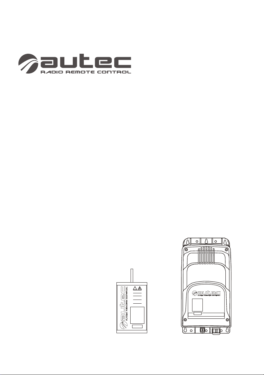
AC Receiver System
USER’S MANUAL
!!
Prima dell'accensione leggere il manuale d’uso.
Attenersi alle norme di sicurezza.
Togliere l’alimentazione in caso di apertura.
Before switching on please read the user manual.
Adhere to safety rules.
Disconnet power source before opening.
Vor Inbetriebnahme die Gebrauchsanleitung
lesen. Sicherheitsnormen beachten.
Die Speisespannung muss ausgeschaltet
werden, falls der Empfänger geöffnet wird
Avant d’allumer l’engine, lire le manuel de
l’utilisateur.
Respecter le consignes de sécurité.
Couper l’alimentation avant d’ouvrir le boîtier.
Antes de encenderlo leer el manual.
Atenerse a las normas de seguridad.
Desconectar la alimentación antes de abrir.
Page 2

Follow the indications and warnings given by the machine producer regarding the machine
controlled by the radio remote control.
The information contained in this manual considers a representative configuration of the
radio remote control: please find radio remote control real configuration in the technical data
sheet (attached to the manual).
If this manual is lost or damaged, ask for a copy from AUTEC. Please specify the serial
number of the relative radio remote control.
Contact AUTEC if any of the instructions and/or warnings given in this manual are not clear.
The information contained in this manual is subject to modification without notice and is not
binding.
No parts of this manual may be reproduced by any means without the written permission of
AUTEC (including recording and photocopying).
Page 3
LIE&LAA0
1
Index & Conventions
1
INDEX & CONVENTIONS
INDEX
Page
1
2
Introduction
3
Receiving units
4
Warnings for installation
5
Warnings for maintenance
6
Light signals
7
Programming
8
Receiving unit diagnostic
2
5
8
10
11
12
14
CONVENTIONS
In this manual, all important information is indicated using the following symbols and
conventions:
!
abcd. . .
abcd. . .
: WARNINGS
: TECHNICAL DATA
abcd. . .
abcd. . .
: INSTRUCTIONS
: IMPORTANT TEXTS
THIS MANUAL REFERS EXCLUSIVELY TO THE RECEIVING UNIT: THE GENERAL
USAGE WARNINGS ARE GIVEN IN THE TRANSMITTING UNIT MANUAL.
BEFORE INSTALLING, STARTING AND USING THE RADIO REMOTE CONTROL, THIS
MANUAL MUST BE READ AND UNDERSTOOD CAREFULLY BY ALL PEOPLE WHO
INSTALL, USE AND CARRY OUT MAINTENANCE ON THE RADIO REMOTE CONTROL.
Page 1
Page 4

LIE&LAA0
2
INTRODUCTION
Industrial radio remote controls are used to command
machines from a distance. Each industrial radio
remote control is made up of a portable transmitting
unit, from which the user can remotely control the
machine, and a receiving unit installed on board the
machine itself.
The transmitting unit uses radio frequencies to
transmit a coded message which contains a value
called address. Each receiving unit can only decode
the messages coming from its own transmitting unit
with the same address.
This excludes the possibility of an interference
activating any system function. If the radio frequency
transmission is disturbed, incorrect or interrupted, the
receiving unit autonomously stops the whole system.
Each radio remote control complies with Part 15 of the FCC Rules.
Operation is subject to the following two conditions:
(1) this device may not cause harmful interference, and
(2) this device must accept any interference received, including interference that may
cause undesired operation.
!
Changes or modifications not expressly approved by the party
responsible for compliance could void the user’s authority to operate
the equipment.
Transmitting
unit
Receiving
unit
NOTE: This equipment has been tested and found to comply with the
limits for a Class B digital device, pursuant to Part 15 of the FCC Rules.
These limits are designed to provide reasonable protection against
harmful interference in a residential installation. This equipment
generates, uses and can radiate radio frequency energy and, if not
installed and used in accordance with the instructions, may cause
harmful interference to radio communications. However, there is no
guarantee that interference will not occur in a particular installation. If
this equipment does cause harmful interference to radio or television
reception, which can be determined by turning the equipment off and
on, the user is encouraged to try to correct the interference by one or
more of the following measures:
-- Reorient or relocate the receiving antenna.
-- Increase the separation between the equipment and receiver.
-- Connect the equipment into an outlet on a circuit different from that to
which the receiver is connected.
-- Consult the dealer or an experienced radio/TV technician for help.
Page 2
Page 5
LIE&LAA0
!
Autec cannot be held responsible if the radio remote control is
installed on applications that are different from those permitted
PERMITTED USES
:
Material lifting machines (construction cranes, industrial bridge cranes,
machines for moving material in general, . . . )
FORBIDDEN USES
Machines installed in areas where equipment with explosion-proof
characteristics are being used.
Machines for moving, raising and transporting people.
Alll machines must undergo a risk analysis; therefore it is necessary to evaluate, within
the limits of this analysis, if the machine can be radio remote controlled.
The machine producer and/or the person who decides upon radio remote control use
and installation is responsible for this analysis.
Autec cannot be held responsible if the risk analysis is not carried out correctly.
To guarantee correct radio remote control operation, all current regulations regarding
safety at work and accident prevention should be respected. All current user country
national laws regarding the use of both the machine and the radio remote control MUST
ALWAYS be respected.
Autec cannot be held responsible if the radio remote control is used in unlawful
working conditions.
System must be installed by a licensed technician and in accordance with all
relevant local, state/provincial and federal regulations, including but not limited to
NEC, OSHA, CE etc.
.
!
In any cases of emergencies, faults or damaged parts, ALWAYS stop
the “machine + radio remote control” system until the problem has
been solved.
Any damaged parts can ONLY be replaced by authorised
Autec personnel or service representative, and only using original Autec
spare parts.
Page 3
Page 6
LIE&LAA0
INSTRUCTIONS FOR DOCUMENT MANAGEMENT
The following minimum documentation is supplied with each radio remote
control:
- transmitting unit manual
- receiving unit manual
- battery charger manual
- a guarantee certificate
- the radio remote control technical data sheet.
Make sure that the following documents have been supplied: if they are not, request
them from Autec. Please specify the radio remote control serial number.
The conditions of the radio remote control guarantee are given in the “Certificate of
Guarantee”.
The technical data sheet shows the wiring system between the receiving unit and the
machine. It should be compiled and checked by the installer, who has the responsibility
of correct wiring. Once all necessary checks have taken place the installer must sign the
technical data sheet, which must be kept with the user's manual (always keep a copy of
this data sheet in case it is needed for administrative purposes).
The radio remote control identification and approval data is given on plates that are on
both the transmitting unit and the receiving unit.
The plates MUST NOT be removed from where they are placed or damaged
otherwise the warranty will be forfeited.
CERTIFICATE OF GUARANTEE
TECHNICAL DATA SHEET
IDENTIFICATION PLATES
TECHNICAL DATA
Frequency band
Programmable radio channel
Hamming distance
Probability of non-recognition of error
Typical working range
Time of reply to commands
Time of reply to STOP
Passive emergency time
* refer to paragraph “Programming” in the receiving unit manual, DIP nr. 1 settings.
902 - 928 MHz
32
³ 8
<10 exp-11
100 m
<100 ms
<100 ms
* 0,35 / 1 sec.
!
Following from the status of dip switch no.1 or possibly due to a failure
(of the dip switch itself), a delay up to max 1 second may occasionally
occur between command release and actual deactivation of outputs.
This is due to the characteristics of radio propagation (i.e.: EM
interferences, near out-of-range condition). Care must be taken to
ensure that this could never lead to.
Page 4
Page 7

LIE&LAA0
3
RECEIVING UNITS
The receiving unit
Type R202 and Type R302 can be used with the following transmitting
unit:
- SERIES LIGHT
- SERIES MODULAR
These receiving units are equipped with a safety function called SAFETY that protects
the “radio remote control + machine” system, when it is in neutral (rest position), from
involuntary movements caused by possible radio remote control faults.
RECEIVING UNIT TYPE R202
B
C
A
B
E
D
A
F
C
D
F
E
A
cable holder (opt. plug)
B
data technical plate
C
identification plate
D
POWER light
E
ENABLE light
coaxial cable exit for stylus antenna
F
or for blinker (when present))
Drilling template
A = 150mm
B = 75 mm
C = 357,5mm
D = 118,5mm
E = 167mm
F = 350,5mm
Page 5
Page 8
LIE&LAA0
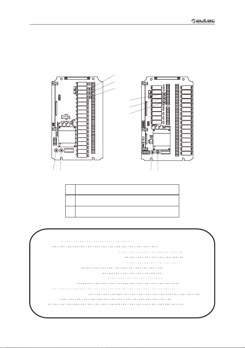
The master boards on this type of receiving unit may be:
- E16B16AC for configurations of up to 16 commands
- E16B22AC for configurations of up to 22 commands (plus extension interface card)
E16B16AC
F1
F2
F3
F1
F2
F3
F4
F5
F1
STOP circuit protection fuse
F2
SAFETY circuit protection fuse
F3
F4
POWER SUPPLY protection fuse
F5
F4
Receiving unit Type R202 TECHNICAL DATA
Power supply
Antenna
Max switching capacity of STOP contacts
Max switching capacity of SAFETY contacts
Max switching capacity of command contacts
Fuse F1 (STOP circuit)
Fuse F2 and F3 (SAFETY circuit)
Fuse F4 and F5 (POWER SUPPLY)
Working temperature
Housing
Minimum protection grade
Dimensions
Weight
*Capacity only valid if both terminals are used for each contact.
If the radio remote control output have been cabled by Autec, please see technical data sheet.
24/48/55/110 Vac ±20% 60 Hz (15VA)
E16B22AC
F5
integrated or dedicated
4A (250Vac)
4A (250Vac)
10A (250Vac)*
4A T 250V (5x20 mm)
4A T 250V (5x20 mm)
1A T 250V (5x20 mm)
-4°F - +158°F
nylon (20% fg)
IP65
(202x381x91) mm
max 3,5 kg
Page 6
Page 9
LIE&LAA0
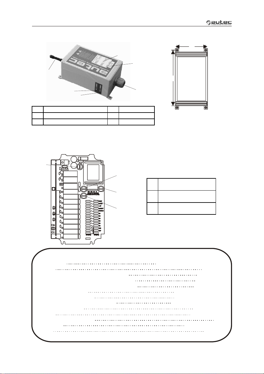
F
RECEIVING UNIT TYPE R302
A
C
B
B
E
D
A
cable holder (opt. plug)
B
identification plate
C
data technical plate
D
E
F
The master board in this type of receiving unit is E16B10AC for configurations of up to 10
commands.
F3
F1
F4
F2
A
POWER light
ENABLE light
antenna
E16B10AC
Drilling template
A=106 mm
B=213,5 mm
STOP circuit protection
F1
fuse
SAFETY circuit
F2
protection fuse
F3
POWER SUPPLY
F4
protection fuse
Receiving unit Type R302 TECHNICAL DATA
Power supply
Antenna
Max switching capacity of STOP contacts
Max switching capacity of SAFETY contacts
Max switching capacity of command contacts
Fuse F1 (STOP circuit)
Fuse F2 (SAFETY circuit)
Fuse F3 and F4 (POWER SUPPLY)
Working temperature
Housing
Minimum protection grade
Dimensions
Weight
*if the radio remote control output have been cabled by Autec, please see technical data sheet
50/110 Vac ±20% 60 Hz (7VA)
dedicated
4A (250Vac)
4A (250Vac)
6A (250Vac)*
4A T 250V (5x20 mm)
4A T 250V (5x20 mm)
0.5A T 250V (5x20 mm)
-4°F - +158°F
Polycarbonate
IP65
(120x200x90) mm
max 2 kg
Page 7
Page 10
LIE&LAA0
!
4
WARNINGS FOR INSTALLATION
Installation should only be carried out by qualified people and in
accordance with installation country rules.
THE INSTALLER
MUST
PLACE the receiving unit vertically, with the cable holder (or plug)
facing down.
FIX the receiving unit at least in four points, using the specific holes
located in the housing.
If installing on machines that vibrate, FIX the receiving unit to the
machine with the appropriate antivibration absorbers.
DO NOT MODIFY or TAMPER WITH the radio remote control, the
machine or its electric panel. DO NOT PERFORATE the receiving unit for
any reason whatsoever.
CHECK that the receiving unit power supply is inside the voltage range
given in the “Technical Data”, and that the voltages and currents being
used do not exceed the maximum permitted values.
DO NOT EXCLUDE the radio remote control safety mechanisms and/or
those present inside the machine.
RESPECT all the machines and for hoisting machines
(see corresponding IEC ).
NEVER SUPPLY the receiving unit directly from the mains. A main
switch should always be present to permit power supply removal.
PLACE the receiving unit so that it is not completely screened by metal
parts and that it must be easily reachable.
REMEMBER to carefully wire the SAFETY contacts in series with the
movement commands inside the receiving unit.
After installation and wiring, ALWAYS CHECK that the maneuvers
carried out are exactly the same as the commands given (in particular
check the STOP command).
FAILURE TO COMPLY WITH THE ABOVE WARNINGS MAY RESULT IN
SERIOUS INJURY OR DEATH TO PERSONNEL AND DAMAGE TO
EQUIPMENT.
prescriptions for
60204-1 and IEC60204-32 prescriptions
Page 8
Page 11

LIE&LAA0
WARNING: The stylus of dedicated antenna (always present in the receiving unit
Type R302, optional for the receiving unit Type R202), must never come in contact
with metal parts.
The installer must CHECK and/or COMPLETE the "Technical Data Sheet" indicating the
date of activation of the system, putting his signature and stamp.
Page 9
Page 12
LIE&LAA0
!
5
WARNINGS FOR MAINTENANCE
ALWAYS ENSURE THAT THE RECEIVING
UNIT HAS BEEN DISCONNECTED FROM THE
POWER SOURCE BEFORE CARRYING OUT
ANY MAINTENANCE WORK.
All the faults should be repaired by authorised
Autec personnel using original Autec spare
parts only.
All control and maintenance interventions carried out on the radio remote control must be
verified and recorded by the person in charge of carrying out maintenance on the machine.
!
Before carrying out maintenance and/or diagnostics it is
recommended to replace the battery with a charged one and ensure the
efficiency of the START key.
Routine maintenance in accordance to the instructions given in this
manual is fundamental for the safe use of the radio remote control.
Read and strictly respect the warnings given in the battery charger
manual in order to lengthen the life of the battery itself.
After each maintenance intervention, always make sure that only the
expected manoeuvres are carried out when the relative commands are
sent by the transmitting unit.
SERV
ICE
Page 10
Page 13
LIE&LAA0
ROUTINE MAINTENANCE
The following instructions allow to maintain the radio remote control in a perfect condition,
guaranteeing it to function safely and correctly for a long period.
Special applications may need more specific routine maintenance interventions to be carried
out at different periods.
These instructions do not in any case substitute the norms and laws that regulate work
safety, nor do they limit the responsibility of the purchaser and user of the radio remote
control.
All given instructions must be followed correctly each time the machine and the radio
remote control are started.
!
If irregularities are noted while carrying out routine maintenance, put
the "machine+radio remote control" system out of order, following the
indications given (see “Receiving unit diagnostic”)
Receiving unit
It is recommended every three months to:
1. remove dust or accumulations of other material from the receiving unit. Never use solvents
or flammable/corrosive materials to clean, and do not use high pressure water cleaners or
steam cleaners.
2. make sure that the receiving unit are structurally integral
3. verify the integrity and connection of the internal wiring to the receiving unit
4. make sue that the panel symbols can be easily seen. If necessary, replace the panel.
5. check identification plate readability and integrity
Electrical operation
It is recommended every six months to:
1. make sure that all the relay contacts of the receiving unit operate correctly, controlling
contact closing when the corresponding manoeuvre is enabled and contact opening when
the manoeuvre is disabled.
2. verify the correct correspondence between the commands that are sent and the
manoeuvres that are carried out.
3. verify that the contact for the SAFETY relay is open when no movement command has
been sent.
External electric conductors
It is recommended every twelve months to:
1. verify integrity along the full length of the cable which connects the receiving unit to the
machine.
2. verify the integrity and the electrical connection of the plugs and the connection socket
3. verify and if necessary replace the strips or other fixing systems
4. make sure that the connecting cable has not deteriorated, above all near the cable holder
Page 11
Page 14
LIE&LAA0
!
SPECIAL MAINTENANCE
Any fault should be repaired by authorised Autec personnel (contact
Service), using original Autec spare parts only.
When it is necessary to carry out special maintenance (radio remote control repair and
replacement of damaged or faulty parts), do not contact anyone other than our
Authorized Service Center. In order to make the intervention faster and more reliable,
please help us identify the radio remote control correctly and completely by giving:
- the serial number
- the purchase date (given on the guarantee)
- description of the problem found
- the address and telephone number of the place where the radio remote control is being
used
- the name of the person to be contacted
- the name of the company that supplied the radio remote control.
Before speaking with a service technician, it is advisable to make sure that the
given instructions have been followed correctly.
When scrapping, entrust the radio remote control to the separate scrap collecting
services in the country of use.
Please pay particular attention when recycling the batteries, applying local rules. Do not
throw them away with domestic trash.
AUTHORIZED SERVICE CENTER
DISPOSAL
Page 12
Page 15

LIE&LAA0
6
LIGHT SIGNALS
On each receiving unit
there are:
a POWER lamp
indicates the presence of power
supply in the receiving unit
an ENABLE lamp
which indicates radio link on
between the transmitting unit
and receiving unit
a LED
for each relay
on the master board,
which indicates
the activation of that relay
On the receiver module there are three LEDs, which indicate:
1. power supply
2. radio connection
3. frequency scanning search.
1 2 3
Page 13
Page 16
LIE&LAA0
!
7
PROGRAMMING
The dip switches must be programmed when the receiving unit is not
powered and can be done only by authorised personnel.
The incorrect closure of the receiving unit can compromise seal
between the casings and thereby the protection grade from dust and
water.
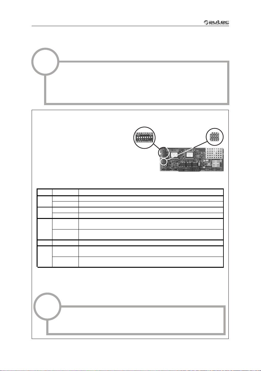
DIP SWITCHES ON E16SRXUS1 RADIO RECEIVING MODULE
The group of eight dip switches found in
the module permits the programming of
different operating mode and the setting
of operating frequency.
The programming set in the other group
of four dip switches must never be
modified.
Group of 8 dip switches
DIP POS.
1 (*)
2 (**)
3
3 - 7 ON/OFF
8
(*) With the MK10, MK12, MJ transmitting unit the dip switch should be at ON.
(**) With the MK12 transmitting unit the dip switch should be at ON.
!
ON
OFF
ON
OFF
ON
OFF
ON
OFF
These eight dip switches must be programmed in the same manner
as the group of 8 dip switches (excluding DIP 1) present in the radio
module of the transmitting unit (see manual).
Deactivated of low battery warning from horn on machine
Activation of low battery warning from horn on machine
With DIP 8 OFF automatic scan mode of the frequencies
With DIP 8 OFF automatic scan mode of the frequencies
With DIP 8 ON see “Appendix: Frequency Table”
DIP 3 - DIP 7 (see “Appendix: Frequency Table”)
Automatic scan mode of frequencies in the band selected with DIP 3
Group of 8
dip switches
DESCRIPTION
Passive emergency at 0,35 second
Passive emergency at 1 second
in the 915 - 928 MHz
in the 902 - 915 MHz
Manual selection of frequencies with
(DIP 4 – DIP 7 not relevant)
Group of 4
dip switches
Page 14
Page 17
LIE&LAA0
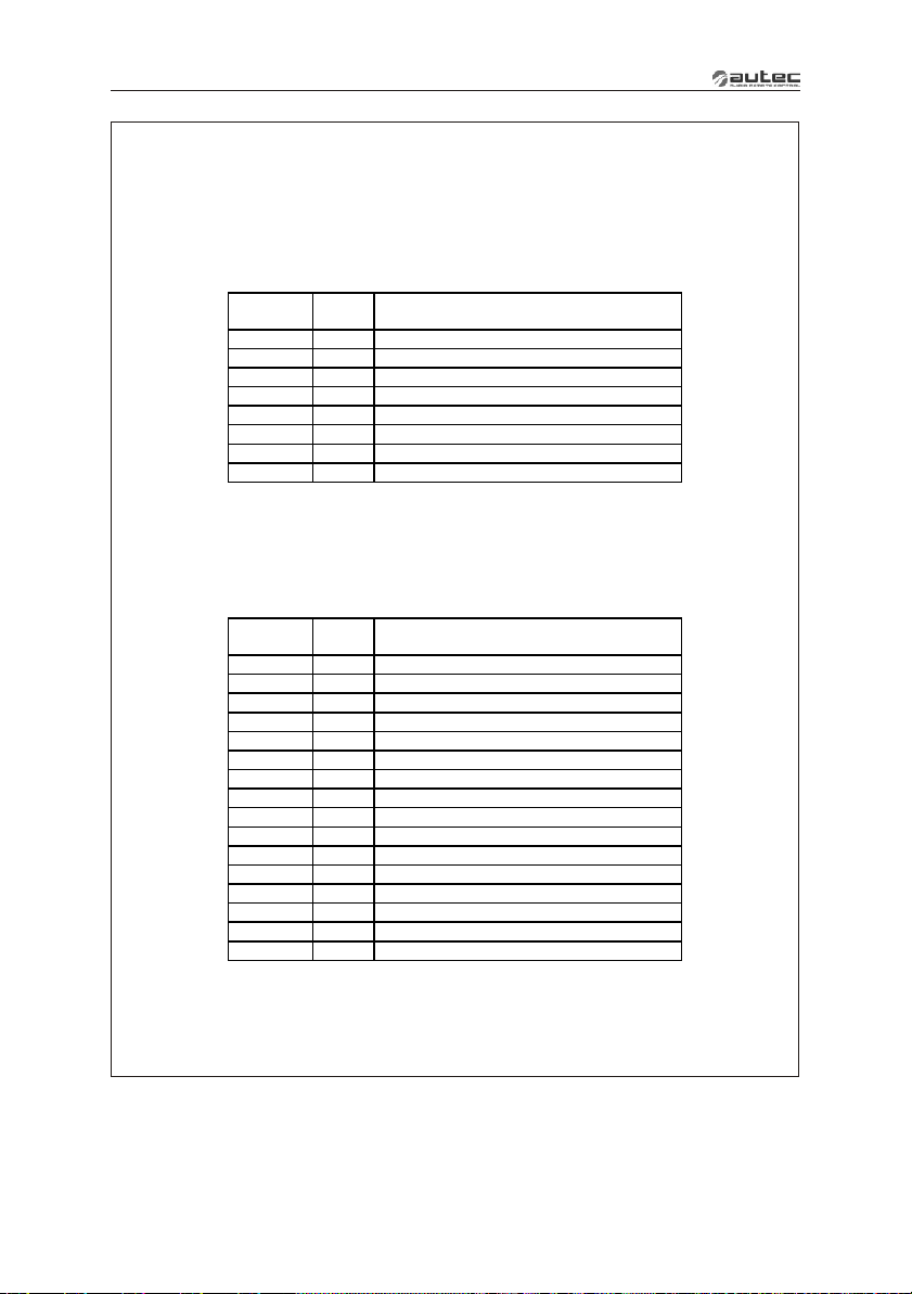
DIP SWITCHES ON MASTER BOARDS
There are a number of dip switches on the E16B16AC and E16B22AC master boards for
programming various functions of the radio remote control, as explained in the following
tables:
DIP SWITCHES ON E16B16AC MASTER BOARD
DIP
SWITCH
* With the LK, VEGA E transmitting units the dip switch is not used and should be at OFF.
** With the LK transmitting units the dip switch is not used and should be at OFF.
*** E4 and E can be disconnected simply by activating them in the reverse order (after you have activated E2 (or E1)
and, therefore, maintained by E2 (or E1)). The same is true for E8 and E7 with E5 (or E6).
POS.
SEL.
1 ON E8 activate also E7
1 OFF function disabled *
2 ON E10 activate also E9
2 OFF function disabled **
3 ON E3 held by E2 (or E1) and E4 by E3 ***
3 OFF function disabled
4 ON E7 held by E5 (or E6) and E8 by E7 ***
4 OFF function disabled
DESCRIPTION
DIP SWITCHES ON E16B22AC MASTER BOARD
DIP
SWITCH
* With the LK transmitting units the dip switch is not used and should be at OFF.
** With the SIRIO E transmitting units the dip switch is not used and should be at OFF.
*** E4 and E3 can be disconnected simply by activating them in the reverse order (after you have activated E2 (or E1)
and, therefore, maintained by E2 (or E1)). The same is true for E8 and E7 with E5 (or E6).
With the MK10 and MK12 transmitting units the dip switches are not used and should all be at OFF.
POS.
SEL.
1 ON E10 activate also E9
1 OFF function disabled *
2 ON E12 activate also E11
2 OFF function disabled
3 ON E14 activate also E13
3 OFF function disabled
4 ON E16 activate also E15
4 OFF function disabled
5 ON E18 activate also E17
5 OFF function disabled
6 ON E20 activate also E19
6 OFF function disabled
7 ON E3 held by E2 (or E1) and E4 by E3 ***
7 OFF function disabled **
8 ON E7 held by E5 (or E6) and E8 by E7 ***
8 OFF function disabled **
DESCRIPTION
Page 15
Page 18
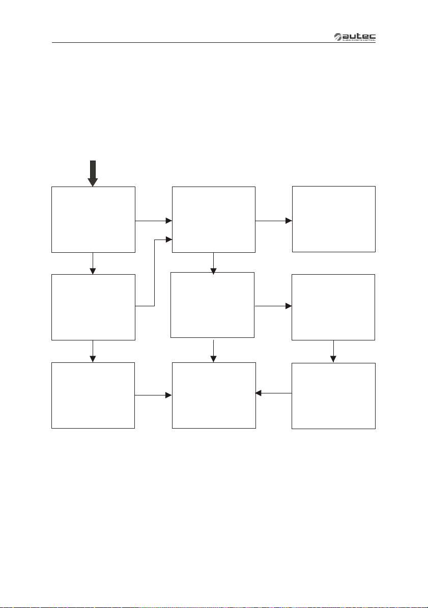
LIE&LAA0
8
RECEIVING UNIT DIAGNOSTIC
If the “machine+radio remote control” system does not start, check if the problem is caused
by the radio remote control or the machine. Before carrying out any verifications, check the
functioning of the machine with the cable control panel: if it does not switch on, the problem
lies with the machine itself.
If, on the other hand, the machine can only be switched on using the cable control panel, the
problem lies with the radio remote control. In this case, follow diagnostics procedure for the
transmitter unit and then proceed as follows:
Is the “POWER”
light lit?
YES YES
Is the “ENABLE”
light lit?
NO
Carry out the
frequency
change procedure
(see transmitting
unit manual)
Does the
machine start?
YES
Is the connecting
plug between the radio
NO
remote control and the
machine correctly
connected?
Remove power
from the receiving
unit and open it.
Check fuses.
Are they blown?
NO
CALL TECHNICAL
ASSISTANCE
YES
Correctly insert
NO
NO
NO
the connecting plug
and start the radio
remote control.
the power supply
connections.
blown fuses. Connect
to power source
and switch on
radio remote control.
machine start?
Check
Replace
Does the
Page 16
Page 19
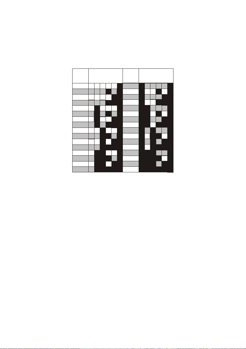
Appendix: FREQUENCY TABLE
E16SRXUS1
DIP SWITCH DIP SWITCH
MHz MHz
4
3
OFF OFF OFF
OFF
902.150
903.050
903.850
904.650
905.525
906.325
907.175
907.975
908.850
909.650
910.450
911.250
912.125
912.925
913.775
914.525
OFF OFF
OFF
OFF OFF
OFF
OFF OFF OFF
OFF OFFONOFF
OFF
OFF OFF
OFF
ON
OFFONOFF
OFF
OFFOFF
ON
ON
OFF
ON
OFF
OFF
ON
OFF
OFF
OFF
OFF
ON
OFF OFF
OFF
ONON
OFF
ON
ON
OFF
8
7
ON
OFF OFF OFF OFF
ON
ON
OFF
ON
ON
OFF
ON
ON
ON
ON
ONON
ON
ON
ON
ONON
ON
ON
OFFOFF
OFF
ON
ON
OFF
ON
ON
OFF
ONONON
ON
ONON
OFF
ON
OFF
OFF
ON
ON ON
ON
ONONON ON
915.350
916.250
917.050
917.850
918.675
919.525
920.375
921.175
922.050
922.850
923.650
924.450
925.325
926.175
926.925
927.725
3
ON
ON
ON
ON
ON
ON
ON
ON
ON
ON
ON
ON
ON
ON
ON
ON
OFF OFF
OFF OFF
OFF OFF
ON
OFF
OFF
OFF
4
OFF OFFONOFF
ON
OFF OFF
OFFONOFF
OFF
ON
ON
ON
ON
ON
ON
ONON
ON
ON
ONON ON
5566
7
8
ON
OFF
ON
ON
OFF
ON
ON
OFF
ON
ON
ON
ON
ON
ON
ON
ON
ONON
ON
OFFOFF
OFF
ON
ON
OFF
ON
ON
OFF
ONON
ON
ON
ON
OFF
OFF
OFF
ON
ONON
ON
OFF
ON
ON
ON
Page 20

Via Pomaroli, 65
36030 Caldogno (VI) ITALY
Tel : ++39 - 0444/901000 r.a.
Fax: ++39 - 0444/901011
email: [email protected]
http://www.autec.it
 Loading...